1
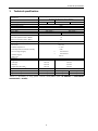
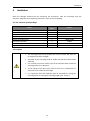
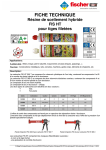
Technical specification centrifuge No.: user manual - Cat. No.: MPW-54 20054/.EN 2014-12-09 USER MANUAL LABORATORY CENTRIFUGE MPW-54 READ IT BEFORE USE! MPW MED. INSTRUMENTS, 46 Boremlowska Street, 04-347 Warsaw/Poland tel. +48 22 610 81 07 (service), fax +48 22 610 55 36 [email protected], www.mpw.pl 1 Technical specification WARNING SIGNS AND HAZARD ICONS WARNING! Warning of potential injury or health risk. DANGER! Risk of electric shock with potential for severe injury or death as a consequence. DANGER! Biohazard with potential for risk to health or death as a consequence. DANGER! Risk of explosion with potential for severe injury or death as a consequence. This manual was prepared with special care. MPW MED. INSTRUMENTS may change the manual at any time and without notice because of improvements and inaccuracies of current information. 2 Technical specification Content 1 TECHNICAL SPECIFICATION .................................................................................................................... 4 2 APPLICATION ......................................................................................................................................... 5 3 SAFETY NOTE ......................................................................................................................................... 6 3.1 PERSONNEL .................................................................................................................................................. 6 3.2 GUARANTEE.................................................................................................................................................. 6 3.3 LOADING THE ROTOR ...................................................................................................................................... 7 3.4 CURRENT PROTECTION .................................................................................................................................... 8 3.5 SAFETY HINTS ................................................................................................................................................ 8 3.6 MAINTENANCE CONDITIONS............................................................................................................................. 9 3.7 SAFETY PRECAUTIONS ..................................................................................................................................... 9 4 INSTALATION ....................................................................................................................................... 11 4.1 THE CONTENTS OF THE PACKAGE ..................................................................................................................... 11 4.2 LOCATION .................................................................................................................................................. 11 5. OPERATING AND DESIGN ...................................................................................................................... 12 5.1 DESCRIPTION OF CENTRIFUGE ......................................................................................................................... 12 5.2 CONTROL ELEMENTS ..................................................................................................................................... 12 5.3 ROTOR AND ACCESSORIES INSTALLATION........................................................................................................... 13 5.4 CONTROL DEVICE ......................................................................................................................................... 13 5.5 SET UP PARAMETERS..................................................................................................................................... 13 5.6 SAFETY FEATURES......................................................................................................................................... 14 6. CENTRIFUGING ...................................................................................................................................... 15 6.1 CONTROL PANEL .......................................................................................................................................... 15 6.2 HOLD MODE .............................................................................................................................................. 16 6.3 CENTRIFUGING FINISH ................................................................................................................................... 16 6.4 SIGNALLING STATES OF CENTRIFUGE ................................................................................................................. 17 6.5 MAINTENANCE OF CENTRIFUGING ELEMENTS ..................................................................................................... 18 6.6 STERILIZATION ............................................................................................................................................. 19 6.7 CHEMICAL RESISTANCE .................................................................................................................................. 21 7. GUARANTEE, SERVICE.......................................................................................................................... 22 8. DISPOSAL ............................................................................................................................................ 23 9. MANUFACTURER’S INFO ..................................................................................................................... 24 10. ANNEXES ............................................................................................................................................. 25 ADDITIONAL ACCESSORIES DECLARATION OF CONFORMITY DECLARATION OF DECONTAMINATION (REPAIR) DECLARATION OF DECONTAMINATION (RETURN) 3 Technical specification 1 Technical specification manufacturer type mains voltage L1+N+PE, ±10% frequency, ±10% connected load (max) overcurrent protection capacity (max) speed – RPM force – RCF running time „MPW MED. INSTRUMENTS” SPÓŁDZIELNIA PRACY, Boremlowska 46 Street, 04-347 Warsaw MPW - 54 MPW – 54s 230V 115V 230V 115V 50/60Hz 60W fuse WTA-T 2A 250V 120ml 3500, 5800, 1000, 3500, 3122 1137 01:00 30:00 – [min., s] (step 1min.) short-time operation mode – SHORT no continuous operation mode – HOLD electromagnetic compatibility ambient conditions set-up site yes according to PN-EN 55011 PN-EN 61010-1 (pkt.1.4.1) indors only ambient temperature 2 ÷ 40C humidity (maximum relative humidity) < 80% excess-voltage category II pollution degree 2 PN-EN 61010-1 PN-EN 61010-1 safety area dimensions height (H) 180 mm 180 mm width (W) 220 mm 220 mm depth (D) 270 mm 270 mm 367 mm 56 dB 4 kg 4 kg 367 mm 56 dB height with open lid(Hoc) noise level weight of centrifuge 230V weight of centrifuge 230V 300 mm 4kg 4 kg 4 kg 4 kg There is a possibility of using power inverter 12DC/230AC (look: 10.ANNEXES → ADDITIONAL ACCESSORIES → OTHER) 4 Application 2 Application The MPW-54 is a table top laboratory centrifuge for in vitro diagnostic (IVD). Device is used for separation samples taken from people's, animal’s and plant’s components of different densities, under the influence of the centrifugal force, to provide information about their biological state. Its construction ensures easy operation, safe work and wide range of applications at laboratories engaged in routine medical analyses, biochemical research works etc. This centrifuge is not biotight and therefore during centrifugation of preparations requiring biotightness one has to use closed and sealed containers and rotors. In the centrifuge, it is prohibited to centrifuge caustic, inflammable and explosive preparations. 5 Safety notes 3 Safety notes 3.1 Personnel Laboratory centrifuge can be operated by laboratory personnel after getting acquainted with user manual. User manual shall be always held near the centrifuge. The centrifuge can not be misused. Guarantee period amounts to minimum 24 months (unless otherwise specified in the purchase documents). The service life of the centrifuge specified by the manufacturer amounts to 10 years. After termination of guarantee period it is necessary to carry out yearly technical inspections of the centrifuge. Manufacturer reserves the right to make technical changes in manufactured products. Maximum period of storage of not used centrifuge amounts to 1 year. After this period, a service authorized by manufacturer should carry out technical inspection of the centrifuge. 3.2 Guarantee 6 Safety notes 3.3 Loading the rotor Fix the rotor on the motor axis firmly. Avoid unbalance. Load opposite buckets with the same accessories. Centrifugation of the test tubes of different sizes: There is a possibility to centrifuge test tubes of different sizes; however, it is absolutely necessary in such cases that opposite buckets and round carriers be the same. CORRECT INCORRECT It is necessary to insert test tubes symmetrically on the opposite sides It is necessary to insert buckets symmetrically on the opposite sides UWAGA If the centrifuge will run with a large unbalance it will occur dangerous vibrations. Buckets 13080 and 13081 are part of common balanced kit and marked by one number. One should load rotor with buckets from the same kit. FILLING TUBES Fill test tubes outside the centrifuge. Please pay special attention to the quality and proper thickness of the glass test tubes walls. Those shall be test tubes for centrifuges. 7 Safety notes 3.4 Current protection The centrifuge is equipped with thermal current protection. Fuse is situated in the plug-in socket unit at back wall of the centrifuge Supply voltage given on the rating plate has to be consistent with local supply voltage. MPW MED. INSTRUMENTS laboratory centrifuges are 1st safety class devices and they are provided with the three-core cable with the plug resistant to dynamic loadings. Mains socket shall be provided with the safety pin. It is recommended to install emergency cut-out that shall be located far from the centrifuge, near the exit or beyond the room. Before switching on, check whether the centrifuge is connected to power supply correctly. 3.5 Safety hints ROTORS MAINTENANCE Use only accessories in good condition. Protect equipment against maintenance. HAZARDOUS MATERIALS corrosion using accurate preventive Infectious materials could be processed in closed buckets only. It is not allowed to subject to centrifugation toxic or infectious materials with damaged leak proof seals of the rotor or test-tube. Proper disinfection procedures have to be carried out when dangerous substances contaminated the centrifuge or its accessories. EXPLOSIVE AND COMBUSTIBLE MATERIALS It is not allowed to centrifuge explosive and inflammable materials. It is not allowed to centrifuge substances prone to reacting in result of supplying high energy during centrifugation. The centrifuge can not be operated in explosion-endangered areas It is not allowed to centrifuge materials capable of generating inflammable or explosive mixtures when subjected to air. 8 Safety notes 3.6 Maintenance conditions START-UP Prior to switching the centrifuge on, one shall read all sections of this instruction carefully in order to ensure smooth operation and avoid damages of this device or its accessories. In order to protect the centrifuge against unbalance, fill in the test tubes up to the same weight. TRANSPORTATION Centrifuge must not be transported with the rotor mounted on the shaft. GENERAL HINTS One must use original rotors, test-tubes and spare parts only. In case of faulty operation of the centrifuge one shall ask for assistance of service of MPW MED. INSTRUMENTS company or its authorized representatives. It is not allowed to switch the centrifuge on if it is not installed properly or rotor is not fitted correctly. CENTRIFUGES SUBSTANCES It is not allowed to exceed load limit set by the manufacturer. Rotors are intended for fluids of average homogeneous density equal to 1,2 g/cm3 or smaller when centrifugation is carried out at maximum or submaximum speed. In order to avoid overloading of the rotor, please observe the maximum load, which is stored on each rotor. The maximum permissible load is achieved when all the tubes are filled with a liquid of 1,2 g/cm3 density. If the density of the centrifuging liquid is greater than 1,2 g/cm3, a tube can be filled only partially, or limit the speed of a centrifuge, which shall be determined from the formula: n admissible = nmax x g 1,2 = density 3 cm nmax =max speed [rpm] 3.7 Safety precautions For safety reasons, inspections of the centrifuge carried out by the authorized service at least once a year after the period of warranty. The reason for more frequent inspections could be corrosion inducing environment. Examinations should end with issuing report of validation that checks on the technical state of the laboratory centrifuge. It is being recommended to establish document where every repairs and reviews are being registered. Both these documents should be stored in the place of use of the centrifuge. 9 Safety notes INSPECTION PROCEDURES CARRIED OUT BY THE OPERATOR Operator has to pay special attention to the fact that the centrifuge parts of key importance due to safety reasons are not damaged. This remark is specifically important as for: Centrifuge accessories and especially structural changes, corrosion, preliminary cracks, abrasion of metal parts. Screw joints. Inspection of the rotor assembly. Inspection of bioseals of the buckets if such are used. Control of execution of the guarantee yearly technical inspection of the centrifuge. Only the manufacturer-specified holders, included in the equipment list, as well as centrifuge capillaries, which diameter, length and durability are suitable, should be used for spinning in this centrifuge. The use of equipment made by other manufacturers should be consulted with the manufacturer of the centrifuge. It is not allowed to lift or shift the centrifuge during operation, and rest on it. It is nor allowed to stay in the safety zone within 30 cm distance around the centrifuge neither leave within this zone some things, e.g. glass vessels. It is not allowed to put any objects on the centrifuge. COVER OPENING It isn't allowed to open the cover manually in emergency procedure when rotor is still turning. ROTORS It is not allowed to use the rotors and round carriers with signs of corrosion or other mechanical defects. It is not allowed to centrifuge highly corrosive substances which may cause material impairment and lower mechanical properties of rotor and round carriers. It is not allowed to use rotors and accessories not admitted by the manufacturer. Let to use commercial glass and plastic test tubes, which are destined to centrifuging in this laboratory centrifuge. One should absolutely not use poor quality elements. Cracking of glass vessels and test tubes could result in dangerous vibration of the centrifuge. It is not allowed to carry out centrifugation with the rotor caps taken off or not driven tight. 10 Instalation 4 Instalation Open the package. Remove the box containing the accessories. Take out centrifuge from the container. Keep the box and packing materials in case of service shipping 4.1 The contents of the package Quantity (pcs) 1 1 1 1 1 2 1 1 Name Centrifuge MPW-54 Complete clamp Spanner for the rotor Key for emergency cover release Power cord 230V/115V Fuse WTA T2A 250V Petroleum jelly 20ml User manual Cat No. See name plate 17168 17099L 17162 17866/17867 17859 17201 20054.EN 4.2 Location The centrifuge shall not be located near source of heat and shall not be subjected to direct sunlight. The table for the centrifuge shall be stable and shall have flat-levelled table top. It is necessary to ensure a safety zone of the minimum 30cm round the centrifuge from every direction. At the change of the place from cold to warm one, condensation of water will occur inside the centrifuge. It is important then that sufficient time be provided for drying the centrifuge prior to starting the centrifuge again (min. 4 hours). ‘ 11 5. Operating and design 5. Operating and design 5.1 Description of centrifuge New generation of MPW MED. INSTRUMENTS laboratory centrifuges is provided with state-ofthe-art microprocessor control systems, very durable and quiet asynchronous brushless motors and accessories consistent with requirements of the present-day user. The centrifuge has rigid self-supporting structure. Housing was made of ABS. Cover is fixed on steel axles of hinges and from the front it is locked with electromagnetic lock blocking opening during centrifugation. Rotation chamber was made from plastic. Rotors and containers are from aluminum, reductive inserts from the polypropylene. 5.2 Control elements 5 4 1. Control panel 3 3. Hole for emergency lid 2 2. Power switch iiiopening 4. Cover 1 5. Glass inspection 1. General view 4 1. Motor axle 3 2. Rotor 3. Rotor lid 2 4. Complete clamp 1 2 1. Mains socket 1 2. Fuse socket 3. Back of the centrifuge 2. Angle rotor assembly 12 5. Operating and design 5.3 Rotor and accessories installation Connect the centrifuge to the mains (master switch on left side of the centrifuge). Open the cover of the centrifuge by pressing the COVER key. Prior to putting the rotor in, one has to check if the rotating chamber is free of impurities, e.g. such as dust, glass splinters, residues of fluids that must be taken away. One shall fit the rotor on the motor shaft driving it home on the cone. Fitting the rotor too shallow will result in lack of identification of the rotor after start of the centrifuge, displaying the error message and stopping the centrifuge. Screw-in the bolt for fixing the rotor (clockwise) and screw it tightly home with the supplied spanner for the rotor. In case of rotors designed with the cover they must not be used without it. Rotor covers must be closed exactly. Rotor covers ensure smaller drags of the rotors, proper setting of the test-tubes and airtight sealing. Fill test tubes outside the centrifuge. Put on or screw the caps on vessels and rotors (if applicable). In case of centrifuging in an angle rotor, test tubes (buckets) have to be filled properly in order to prevent from pouring fluids during centrifuging. Centrifuge will tolerate small weight differences occurring during loading of rotors. However it is recommended to equalize vessels loads as much as possible in order to ensure minimal vibrations during operation. When the centrifuge is started with large imbalance, the unbalance control system will switch-off the drive system and error signal will be transmitted. On the monitoring panel, error message will be displayed. Threaded parts shall be lubricated with the petroleum jelly. For replacement of the rotor one shall unscrew clamping and then grab the rotor with both hands at opposite sides, taking it away from drive shaft by pulling it up. 5.4 Control device The microprocessor control unit of the centrifuge ensures broad possibilities of providing, realisation and reading of work parameters. 5.5 Set up parameters Data setting and read-out system forms hermetically closed keyboard with distinctly accessible operation points. Easily readable display signaling time to end of centrifuging and set mode of speed. It make easy for the operator to the registration status of the device. Control system provides possibility of: set up speed mode (H) 5800 or (L) 3500 rpm (MPW-54), (H) 3500 or (L) 1000 rpm (MPW-54s), set up time of centrifuging in the range 1÷30 min or hold time mode. 13 5. Operating and design 5.6 Safety features Cover lock The centrifuge can be started only with properly closed cover. While, the cover can be opened only after stopping the rotor. In case of emergency opening of the cover during operation, the centrifuge will be immediately switched-off and the rotor will brake till complete stopping. Rest state inspection Opening of the centrifuge’s cover is possible only with the rotor in the state of rest. EMERGENCY COVER RELEASE In case of e.g. mains failure it is possible to open cover manually. At first, one must be sure that rotor is not in the move (use inspection glass). On the right-hand side of the casing there is a hole. Insert emergency opening key (17162) into the hole. It is not allowed to use emergency cover release when the rotor is running! 14 6. Centrifuging 6. Centrifuging Power switching ON/OFF is carried out with master switch situated on the side wall of the centrifuge. All settings on the centrifuge are done by means of the control panel. 6.1 Control panel The control panel (equipped with membrane keyboard) placed on the front casing serves the purpose of controlling centrifuge operation. STATUS/SPEED display show information about state of centrifuge (left side) and speed mode (right side). TIME display show information about time remain to the end of centrifuging. 4. Control panel Buttons application: ► START Start of centrifuging STOP Cancel of centrifuging COVER Open the lid ▲ TIME Set up runtime (in 1 minute step) L/H SPEED Change speed mode 15 6. Centrifuging 6.2 HOLD mode continuous mode (centrifuging until pressing STOP) HOLD mode In order to run the HOLD mode, set the time value to - - 6.3 Centrifuging finish WAYS OF FINISH THE CENTRIFUGING After reaching the preset working time centrifuging is stopped. Before the expiry of the set time, you can interrupt the cycle by pressing the STOP x1 16 6. Centrifuging 6.4 Signalling states of centrifuge 17 Cover is locked Cover is open Rotor is running (speed is increasing or constant) – mark turn counter-clockwise Rotor is running (breaking) – mark turn clockwise Rotor is running, time is counting – dot next to time indication is blinking Cycle cancelled or end of centrifuging – a dot next to the time indication stops flashing, after braking the rotor, four short beeps are issued 6. Centrifuging Centrifuging in high rotational speed Centrifuging in low rotational speed Centrifuge has memory for remembering the last settings even after turn off and turn on the centrifuge 6.5 Maintenance of centrifuging elements In order to increase durability of gaskets and threaded places, it shall be lubricated with petroleum jelly (cat. No 17201). Cleaning of the accessories In order to ensure safe operation one shall carry out in regular way periodical maintenance of the accessories. Rotors, buckets and round carriers have to withstand steady high stresses originating from the centrifugal force. Chemical reactions as well as corrosion (combination of variable pressure and chemical reactions) can cause corrosion or destruction of metals. Hard to observe surface cracks increase gradually and weaken material without visible symptoms. In case of observation of surface damage, crevice or other change, as well as the corrosion, the given part (rotor, bucket, etc.) shall be immediately replaced. In order to prevent corrosion one has to clean regularly the rotor with the fastening bolt, buckets and round carriers. Cleaning of the accessories shall be carried out outside of the centrifuge once every week or still better after each use. Then, those parts shall be dried using soft fabric or in the chamber drier at ca. 50°C. Especially prone to the corrosion are parts made of aluminium. For cleaning them one should use neutral agent of pH value 6÷8. It is forbidden to use alkaline agent of pH > 8. In this way, the useful service life of the device is substantially increased and 18 6. Centrifuging susceptibility to corrosion is diminished. Accurate maintenance increases the service life as well and protects against premature rotor failures. Corrosion and damages resulting from insufficient maintenance could not be subject of claims lodged against the manufacturer. One can use all standard disinfectants. The centrifuges and accessories are constructed from various materials and one should to take into account possible variety of materials. During sterilization by means of steam one should to consider temperature resistance of individual materials. 6.6 Sterilization sterilization * PS SAN PMMA PC PVC POM PE-LD PE-HD PP PMP ECTFE ETFE PTFE FEP/PFA FKM EPDM NR SI radiation β radiation γ C2H4O (ethylene oxide) formalin, ethanol 25 kGy ● ○ ● ● ○ ● ● ● ● ● ○ ● ○ ● ● ● ● ● ● ● ● ● ● ● ● ● ● ● ● ● ● ○ ● ● ● ● ● ● ○ ● ○ ○ ○ ○ ○ ○ ● ● ● ● ● ● ● ● ● ● ● ● 121°C, 20 min ○ ○ ○ ●1) ○2) ●1) ○ ○ ● ● ● may be used ○ cannot be used * Laboratory vessels have to be exactly cleaned and rinsed with the distilled water before the sterilization in the autoclave. It is always necessary to remove closures from containers! 1) The frequent steam sterilization reduces mechanical durability! PC test tubes may become useless. 2) Except PVC hoses which are resistant to the steam sterilization in the temperature 121°C 19 6. Centrifuging ○/● ○/● ○ ○ ○ ○ ● ○ ○ ○/● ○ ○ ○ ○ ● ○/● ● ○ ○ ○ ○ ○/● ○ ○/● ○ ○ ○ ○/● ● ○ ○ ○ ○ ○/● ○ ○/● ○ ○ ○ ○ ● ○ ○ ○ ● ● ○ ● ○ ○ ● ○/● ● ○ ● ● ○ ○ ○ ● ● ● ● ● ● ● ○/● ● ● ○ ● ● ● ● ● ● ○/● ○/● ○/● ● ● ○ ● ○/● ○/● ● ● ● ○/● ○/● ○/● ● ● ○ ● ○/● ○/● ● ○/● ● ○/● ○/● ● ● ○ ○/● ○ ○ ● ● ○/● ○ ● ● ● ● ○ ● ● ● ● ● ● ● ● ● ● ● ● ● ● ● ● ● ● ● ● ○ ○ ○ ○ ○ ● ○/● ○/● ○/● ○/● ○/● ● ● ○/● ○ ○/● ● ● ○/● ○ ○ ○ ● ○/● ● ○/● ○ ○ ○ ○/● ○ ○ ○ ○ ● ○/● ● ○/● ○ ○ ○ ○/● ○ ○ ○ ○ ○/● very good Permanent action of the substance does not cause damage through 30 days. The material is able to be resistant through years. good to limited Continuous action of the substance causes insignificant and partly reversible damage through the period of 7-30 days (e.g. puffing up, softening, reduced mechanical durability, discolouring). limited The material should not have the continuous contact with the substance. The immediate occurrence of damage is possible (e.g. the loss of mechanical durability, deformation, discolouring, bursting, dissolving). Plastics polystyrene ECTFE ethylene/chlorotrifluoroethylene styrene-acrylonitrile ETFE ethylene/tetrafluoroethylene polymethyl methacrylate PTFE polytetrafluoroethylene polycarbonate FEP tetrafluoroethylene/perfluoropropylene PVC polyvinyl chloride PFA tetrafluoroethylene/perfluoroalkylvinylether POM acetal polyoxymethylenel FKM fluorcarbon rubber PE-LD low density polyethylene EPDM PE-HD high density polyethylene NR natural rubber polypropylene SI silicon rubber PS SAN PMMA PC PP PMP alkalis ahs ether esters haloid hydrocarbons ○ ○ ○ cyclic hydrocarbons weak or diluted acids ○ ○ aldehydes PS SAN PMMA PC PVC POM PE-LD PE-HD PP PMP ECTFE ETFE PTFE FEP PFA FKM EPDM NR SI oxidizing substances strong or concentrated acids ● ● ○ ○ cyclic alcohols ketones Chemical resistance of plastic polymethylpentene 20 ethylene propylene diene 6. Centrifuging DANGER! For centrifuging infectious materials it is necessary to use hermetically closed buckets, in order to prevent they migration into the centrifuge. Rotors, buckets and round carriers can be sterilized in autoclave with temperature 121 – 124°C and pressure 215 kPa during 20 min. In the centrifuge, disinfectants and cleaning agents generally used in medical care should be used (e.g. Aerodesina-2000, Lysoformin 3000, Melseptol, Melsept SF, Sanepidex, Cutasept F). Additional accessories can be sterilized using autoclave depending on material that they are made of. See table STERILIZATION. User is responsible for proper disinfections of the centrifuge, if some dangerous material was spilled inside or outside of the centrifuge. During the above mentioned works one must wear safety gloves. 6.7 Chemical resistance One can use all standard disinfectants. The centrifuges and accessories are constructed from various materials and one should to take into account possible variety of materials. During sterilization by means of steam one should to consider temperature resistance of individual materials. DANGER! For centrifuging infectious materials it is necessary to use hermetically closed buckets, in order to prevent they migration into the centrifuge. User is responsible for proper disinfections of the centrifuge, if some dangerous material was spilled inside or outside of the centrifuge. During the above mentioned works one must wear safety gloves. 21 Guarantee, service 7. Guarantee, service Manufacturer grants to the Buyer the guarantee on conditions specified in the Guarantee Certificate. Buyer forfeits the right to guarantee repair when using the device inconsistently with the User manual provisions, when damage results from the User’s fault. Repairs should be carried out in authorized service workshops, granted with the MPW Certificate. The centrifuge shall be sent to repair after decontaminating disinfections. Information about authorized service workshops could be obtained from the Manufacturer. 22 Disposal 8. Disposal When you are disposing the device, the respective statutory rules must be observed. Pursuant to guideline 2002/96/EC (WEEE), all devices supplied after August 13, 2005, may not be disposed as part of domestic waste. The device belongs to 8th group (medical devices) and is categorized in business to business field. The icon of the crossed-out trash can shows that the device may not be disposed as part of domestic waste. The waste disposal guidelines of the individual EC countries might vary. If necessary, contact your supplier. 23 Manufacturer’s info 9. Manufacturer’s info MPW MED. INSTRUMENTS Boremlowska 46 Street 04-347 Warsaw +48 22 610 56 67 22 610 81 07 22 610 55 36 www.mpw.pl e-mail: [email protected] http:// DISTRIBUTOR: 24 sales department service fax ANNEXES 10. ANNEXES Capacity [ml] Tube x L [mm] Catalogue number 7 15 15 10 10 glass Nalgene PP conical bottom PP with cap PP glass 12x100 15119 16x113 15048 17x120 15050 16x108 15053 12x75 15118 Angle rotor (30°) 11101 with buckets 13080 Catalogue number Hole x L [mm] Shape of round carrier bottom Quantity of tubes per rotor Max RCF [g] Max speed [rpm] Centrifuging radius [mm] Time of acceleration [s] Time of decelaration [s] 14082 14083 13,3x30 13,3x30 lack of bottom 6 3120 5800 8,3 15 29 Capacity [ml] 6 5 5 10 Tube with cap PP glass with cap PP with cap PP x L [mm] Catalogue number 11,7x95 15054 12x75 15120 12x85 15419 16x108 15053 Angle rotor (30°) 11101 with buckets 13081 Catalogue number Hole x L [mm] Shape of round carrier bottom Quantity of tubes per rotor Max RCF [g] Max speed [rpm] Centrifuging radius [mm] Time of acceleration [s] Time of decelaration [s] 14082 13,3x30 14083 13,3x30 14082 14083 13,3x30 13,3x30 lack of bottom 6 3120 5800 8,3 15 29 25 14082 13,3x30 14083 13,3x30 ANNEXES Capacity [ml] 7 Tube x L [mm] Catalogue number 15 15 10 10 glass Nalgene PP conical bottom PP with cap PP glass 12x100 15119 16x113 15048 17x120 15050 16x108 15053 12x75 15118 Angle rotor (30°) 11144 with buckets 13080 Catalogue number Hole x L [mm] Shape of round carrier bottom Quantity of tubes per rotor Max RCF [g] Max speed [rpm] Centrifuging radius [mm] Time of acceleration [s] Time of decelaration [s] 14082 14083 13,3x30 13,3x30 lack of bottom 4 3120 5800 8,3 15 29 Capacity [ml] 6 5 5 10 Tube with cap PP glass with cap PP with cap PP x L [mm] Catalogue number 11,7x95 15054 12x75 15120 12x85 15419 16x108 15053 Angle rotor (30°) 11144 with buckets 13081 Catalogue number Hole x L [mm] Shape of round carrier bottom Quantity of tubes per rotor Max RCF [g] Max speed [rpm] Centrifuging radius [mm] Time of acceleration [s] Time of decelaration [s] 14082 13,3x30 14083 13,3x30 14082 14083 13,3x30 13,3x30 Brak dna 4 3120 5800 8,3 15 29 26 14082 13,3x30 14083 13,3x30 ANNEXES Capacity [ml] Tube x L [mm] Catalogue number 7 15 10 glass Nalgene PP with cap PP 10 glass 12x100 15119 16x113 15048 16x108 15053 12x75 15118 Angle rotor (30°) 11145 with buckets 13080 Catalogue number Hole x L [mm] Shape of round carrier bottom Quantity of tubes per rotor Max RCF [g] Max speed [rpm] Centrifuging radius [mm] Time of acceleration [s] Time of decelaration [s] 14082 14083 13,3x30 13,3x30 lack of bottom 8 3120 5800 8,3 15 29 Capacity [ml] 6 5 5 10 Tube with cap PP glass with cap PP with cap PP x L [mm] Catalogue number 11,7x95 15054 12x75 15120 12x85 15419 16x108 15053 Angle rotor (30°) 11145 with buckets 13081 Catalogue number Hole x L [mm] Shape of round carrier bottom Quantity of tubes per rotor Max RCF [g] Max speed [rpm] Centrifuging radius [mm] Time of acceleration [s] Time of decelaration [s] 14082 13,3x30 14083 13,3x30 14082 14083 13,3x30 13,3x30 lack of bottom 8 3120 5800 8,3 15 29 27 14082 13,3x30 14083 13,3x30 ANNEXES ADDITIONAL ACCESSORIES: INNE/OTHER nr kat./cat no opis description 16696 Przetwornica napięcia 300W umożliwiająca zasilanie prądem stałym o napięciu 12 V (m.in. z zapalniczki samochodowej) Power inverter 300W (12DC→ 230 AC) (e.g. possibility of supply from the cigarette lighter socket) Only original MPW buckets can be used! One should use tubes which dimensions and durability is proper!Using of tubes from other companies should be consulted with manufacturer of centrifuge. In the centrifuge, disinfectants and cleaning agents generally used in medical care should be used (e.g. Aerodesina-2000, Lysoformin 3000, Melseptol, Melsept SF, Sanepidex, Cutasept F). 28 DECLARATION OF CONFORMITY Product Laboratory centrifuge Model MPW-54 Product classification on the basis of the Directive 98/79/EC Non classified to list A or B and not for self-testing Product complies with the requirements: · Directive 98/79/EC (IVD), including the requirements of harmonised standards: PN-EN ISO 13485:2012 PN-EN ISO 18113-3:2011 PN-EN ISO 13485:2012/AC:2013-03 PN-EN 61010-2-101:2005 PN-EN 13612:2006 PN-EN 61326-2-6:2013-08 PN-EN ISO 14971:2012 PN-EN ISO 62366:2008 · selected harmonized standards of Directive 2006/95/EC (LVD): PN-EN 61010-1:2011 PN-EN 61010-2-020:2008 · Directive 2004/108/WE (EMC) · standard PN-EN ISO 15223-1:2012 „MPW MED. INSTRUMENTS” SPÓŁDZIELNIA PRACY Warsaw, 46 Boremlowska Street Quality policy in line with ISO 9001:2008 Certifying authority Warsaw, 13.11.2014 nr 10.054.03 DECLARATION OF DECONTAMINATION In order to protect our employees please fill out the declaration of decontamination completely before sending centrifuge to the manufacturer (repair). 1. 2. Device ─ type: ……………………………………………………………………………………… ─ serial No.: ……………………………………………………………………………………… Description of decontamination (see user manual) ……………………………………………………………………………………………………………………………………………… ……………………………………………………………………………………………………………………………………………… ……………………………………………………………………………………………………………………………………………… ……………………………………………………………………………………………………………………………………………… 3. 4. Decontamination carried out by: ─ name: ………………………………………………………………………… Date and signature ………………………………………………………………………… DECLARATION OF DECONTAMINATION In order to protect our employees please fill out the declaration of decontamination completely before sending centrifuge to the manufacturer (return). 5. 6. Device ─ type: ……………………………………………………………………………………… ─ serial No.: ……………………………………………………………………………………… Description of decontamination (see user manual) ……………………………………………………………………………………………………………………………………………… ……………………………………………………………………………………………………………………………………………… ……………………………………………………………………………………………………………………………………………… ……………………………………………………………………………………………………………………………………………… 7. 8. Decontamination carried out by: ─ name: ………………………………………………………………………… Date and signature …………………………………………………………………………