1
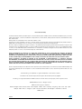
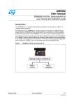
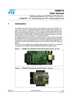
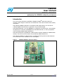
UM0458
User manual
STEVAL-IFS009V1
extension for SN250 network processor
Introduction
This user manual describes the STEVAL-IFS009V1 ZigBee® extension hardware. It
includes a block diagram, schematics of the extension, and a bill of material and assembly
instructions.
The STEVAL-IFS009V1 operates in standalone mode. Alternatively it can be used as
a SN250 ZigBee interface with an application using an STR9 dongle.
The SN250 integrates a 2.4 GHz IEEE802.15.4-compliant transceiver with a 16-bit XAP2b
microprocessor. It features embedded Flash and RAM memories, as well as peripherals
useful to design ZigBee-based applications.
The extension board is supplied with a demonstration firmware loaded in the SN250 Flash
memory. The firmware source code is not provided by STMicroelectronics.
The STEVAL-IFS009V1 is delivered with a CD-ROM containing technical documentation.
This information is also available on ww.st.com/zigbee.
Figure 1.
October 2008
STEVAL-IFS009V1 extension board
Rev 3
1/10
www.st.com
Contents
UM0458
Contents
1
Block diagram . . . . . . . . . . . . . . . . . . . . . . . . . . . . . . . . . . . . . . . . . . . . . . 3
1.1
Schematics . . . . . . . . . . . . . . . . . . . . . . . . . . . . . . . . . . . . . . . . . . . . . . . . . 4
1.2
PCB layout . . . . . . . . . . . . . . . . . . . . . . . . . . . . . . . . . . . . . . . . . . . . . . . . . 5
1.3
Bill of material . . . . . . . . . . . . . . . . . . . . . . . . . . . . . . . . . . . . . . . . . . . . . . . 6
1.4
Connection of STR9 ZigBee extension to the STR9 dongle . . . . . . . . . . . 7
1.5
Board supply . . . . . . . . . . . . . . . . . . . . . . . . . . . . . . . . . . . . . . . . . . . . . . . 7
2/10
Supply from battery . . . . . . . . . . . . . . . . . . . . . . . . . . . . . . . . . . . . . . . . . 7
1.5.2
Battery charging . . . . . . . . . . . . . . . . . . . . . . . . . . . . . . . . . . . . . . . . . . . . 7
1.5.3
Supply directly from pins . . . . . . . . . . . . . . . . . . . . . . . . . . . . . . . . . . . . . 8
1.6
Board storage recommendation . . . . . . . . . . . . . . . . . . . . . . . . . . . . . . . . . 8
1.7
Measurements . . . . . . . . . . . . . . . . . . . . . . . . . . . . . . . . . . . . . . . . . . . . . . 8
1.8
2
1.5.1
1.7.1
Battery measurement . . . . . . . . . . . . . . . . . . . . . . . . . . . . . . . . . . . . . . . 8
1.7.2
Output voltage measurement . . . . . . . . . . . . . . . . . . . . . . . . . . . . . . . . . . 8
Firmware . . . . . . . . . . . . . . . . . . . . . . . . . . . . . . . . . . . . . . . . . . . . . . . . . . 8
Revision history . . . . . . . . . . . . . . . . . . . . . . . . . . . . . . . . . . . . . . . . . . . . 9
UM0458
1
Block diagram
Block diagram
The main features of the extension board are the following:
●
●
●
SPZB250 radio communication module based on SN250 ZigBee network processor
LIS302DL Digital MEMS in LGA14 package (optional)
It can be accessed by the ZigBee network processor through an I2C bus.
STLM75 temperature sensor or compatible device in SO8 package (optional). It is
connected to the ZigBee network processor through an I2C bus.
●
Digital interfaces: one I2C and one SPI interface which can be used indifferently by the
SN250 ZigBee network processor to interface with the STR9 dongle
●
Supply voltage
The extension board can be supplied externally from the STR9 dongle or internally by
an on-board Ion-Li battery. The battery has a capacity of 65 mA hours which allows
approximately one hour of operation. It is charged through a mini USB connector. 2
LEDs can be used to monitor the charging:
–
Red LED: charge in progress
–
Green LED: charge completed
●
1 button connected to the SN250 ZigBee network processor WAKE_UP input
●
3 LEDs connected to the SN250 ZigBee network processor:
●
–
Yellow LED: device connected
–
Green LED: transmission ongoing
–
Red LED: general purpose
A debug port
Figure 2 shows the STEVAL-IFS009V1 extension block diagram.
Figure 2.
STEVAL-IFS009V1 extension block diagram
Debug
port
1 button
3 LEDS
SPZB250
radio communication module
I2C bus
SPI bus
Digital MEMS
LIS302DL
(optional)
Voltage regulator
and Battery
3.3 V
SC2
SC1
Digital connector
(to STR9 dongle)
Temperature
sensor STLM75
(optional)
5V
Mini USB connector
(battery charging)+2 LEDS
ai14155
3/10
4/10
2
PS_DATA
SC1_CLK
9
8
LD24 2.1 V
yellow
1
2 LED_LINK
3V3_BOARD
1
3
5
7
9
11
13
15
17
19
2
4
6
8
10
12
14
16
18
20
CN2
DIGITAL_CON
CONNECTORS to STR9_DONGLE
P80P
P82P
SC2_CLK P22P
SC2_SDA P23P
SC1_CLK P24P
P87P
RSTB
SC1_MISO P26P
TEMP_INT P54
GPIO7
GPIO8
VIN
1
2
3
4
5
330 Ω
-> 4 mA
R12
250 Ω
-> 4 mA
R11
USB_MINI
USB
USB_MIMI
VBUS
DD+
GND
SH1
3.3 V
B22
EXT_INT
LD12 2.0 V
red
1
2
ST1
charge in progress
LD11 2.3 V
green
ST2
1
2
charge done
VIN
C22
10 nF
3.3 V
SIF_MISO
SIF_MOSI
Debug I/F
10
9
8
7
6
5
4
3
2
1
CN1
11
10
9
12
3.3 V
SC2_SDA 13
MEMS_INT
8
MEMS
SAD: 0011101b
GND
14 SC2_CLK
1
13
5
TH
6 7 8
10 kΩ
R17
C12
10 nF
X7R
TH
TPRG GND SD TH
2 kΩ
R18
248 mV < TH < 780 mV where VREF = 1.8 V
VREF
ST1 4
ST2 3
2
1
15 14
R13
2 kΩ
U1
L6924D
IPRE IPRG V
I
PRE END 12 VREF
VREF
VIN
11
VINSNS
VOUT
C13
10
L6924D
ST2
1 µF
VOSNS
9
X7R
ST1
VOPRG
16
24 kΩ
R15
5 min ~ 3 nF at 24 kΩ
U3
LIS302DL
1
2
3
4
5
6
3.3 V
3.3 V
3.3 V
SSP0_NSS
2
GND
C71
1 µF
X7R
2
1
3
2
1
VBAT 3
100 kΩ
for SM6717
VBAT R81
U6
BAT_BH2430
Header
BATERY
VCC
1
1
2
SW2
VBAT
70 kΩ
30 kΩ
BAT_MEA
R62
R61
R26
10 kΩ
NC
VOUT
STM6718
MR_
GND
RST
U8
VCC2
VCC1
4
5
4
5
VBAT
3V3_BOARD
R32 4.7 kΩ
R31 4.7 kΩ
LD2980xM30 - xM33
-->3.00 V
INHIBIT
GND
VIN
U7
SC2_CLK
8
7
6
5
C81
10 nF
C72
2.2 µF
X7R
AM00320
ROH2
ROH1
ST
SW1
1
3.3 V
2
C40
100 nF
3.3 V
3.3 V
C73
100 nF 3
3.3 V
3.3 V
Vdd
A0
A1
A2
C30
100 nF
3.3 V
STLM75
STLM75
SDA
SCL
INT
GND
U4
SC2_SDA
C20
C21
100 nF 10 nF
3.3 V
SC2_SDA 1
SC2_CLK 2
TEMP_INT 3
4
TEMPERATURE SENSOR
SAD: 1001000xb
STR9 SPI Master/Slave (1 means STR9 is master)
SDA/SDI Vdd_io
SCL_SPC
GND
SDO
GND
VCC
GND
VCC
CS
GND
INT_2
INT_1
7
3.3 V
C12 [nF] = ( (Tmax[sec] / 279*10^5) * (1.23[V] / R15[Ω])) / 1.8[V] * 10^9
Iend [A] = (0.05[V] * 1050) / R13 [Ω]
Iprg [A] = ( 1.23[V] * 9500) / R15 [Ω]
PS_DATA
PS_FRAME
RSTB
SIF_LOADB
SIF_CLK
C11
100 nF
X7R
0.5 A, 40 V
STPS0540Z
D11
1
R22
10 KΩ
BUT_INT
2
VOLTAGE REGULATOR
13 BAT_MEA
14 BUT_INT
15 SC1_MOSI
16 SC1_MISO
17 SIF_CLK
18 SIF_MISO
19 SIF_MOSI
20 SIF_LOADB
21 MEMS_INT1
22 TEMP_INT
23 LED_ACTIVE
24 LED_LINK
81
83
84
VIN
85
86
25 SC1_MOSI
27 SSP0_NSS
P55 MEMS_INT1
LD25 2.3 V
green
1
2 LED_ACTIVE
250 Ω
-> 4 mA Link
R25
VDD
GND
GPIO9
GPIO10
SIF_CLK
SIF_MISO
SIF_MOSI
SIF_LOADB
GPIO16
SN250 Zigbee module
300 Ω
-> 4 mA Active
R24
330 Ω
-> 4 mA
R23
12
GPIO2
GPIO1
GPIO0
GPIO12
GPIO11
RSTB
LD23 2.0 V
red
1
2 LED_GP
3.3 V
11
SC2_CLK 10
SC2_SDA
6
7
5
RSTB
GPIO3
GPIO15
GPIO14
GPIO5
GPIO4
GPIO13
GPIO6
U2
Figure 3.
4
PS_FRAME 3
1
LED_GP
1.1
3.3 V
Zigbee
Block diagram
UM0458
Schematics
STEVAL-IFS009V1 extension board schematic
UM0458
1.2
Block diagram
PCB layout
Figure 4.
Top view
Figure 5.
Bottom view
5/10
Block diagram
1.3
UM0458
Bill of material
Table 1 shows the bill of material for the STEVAL-IFS009V1 extension board.
Table 1.
Bill of material
Designator
Footprint
Description
Assembled
Order code
U1
L6924D
L6924D
Yes
ST: L6924D
U2
SN250_ST_module duplicate
SN250 ZigBee
module
Yes
ST: SPZB250
U3
LGA14AD
LIS302DL
Yes
ST: LIS302DL
U4
SO8
STLM75
Yes
ST: STLM75
U6
BH2430
BAT_BH2430
Yes
GM: BH2430 (holder) and
B-LIR2430 (battery)
U7
SOT23-5L
LD2980Cx30
Yes
ST: LD2980Cx30
U8
SOT23-5L
STM6718
Yes
ST: STM6718T
USB
USB_MINI
USB_MINI
Yes
GM: USB MINI B F SMD
(832-177)
CN1
Header 2X5
Debug I/F
Yes
Samtec: FTSH-114-04-FDV
CN2
Header 2X10
DIGITAL_CON
No
GM: BL220G
SW1
Header 1x3
Power switch
Yes
GM: S1G20
SW2
Header1x2
Battery switch
Yes
GM: S1G20
B22
Button_DT2112C
EXT_INT
Yes
GM: P-DT2112C
D11
SOD-123
STPS0540Z
Yes
ST: STPS0540Z
LD11, LD25
D0805
green
Yes
GM: 960-023
LD12, LD23
D0805
red
Yes
GM: 960-024
LD24
D0805
yellow
Yes
GM: 960-025
C12, C21, C22, C81
0805
10 nF
Yes
Farnell: 422-7153 (X7R)
C11, C20, C30, C40,
C73
0805
100 nF
Yes
Farnell: 422-7189 (X7R)
C13, C71
0805
1 µF
Yes
Farnell: 422-7086
(X7R)
C72
1206
2.2 µF
Yes
Farnell: 422-7323 (X7R)
R11, R25
0805
250 Ω
Yes
GM: R0805-250R
R24
0805
300 Ω
Yes
GM: R0805-300R
R12, R23
0805
330 Ω
Yes
GM: R0805-330R
R13, R18
0805
2 kΩ
Yes
GM: R0805-2k
R31, R32
0805
4.7 kΩ
Yes
GM: R0805-4k7
R17, R22, R26
0805
10 kΩ
Yes
GM: R0805-10k
R15
0805
24 kΩ
Yes
GM: R0805-24k
6/10
UM0458
Block diagram
Table 1.
Bill of material (continued)
Designator
Footprint
Description
Assembled
Order code
R61
0805
30 kΩ
Yes
GM: R0805-30k
R62
0805
70 kΩ
Yes
GM: R0805-70k
R81
0805
100 kΩ
No
GM: R0805-100k
1.4
Connection of STR9 ZigBee extension to the STR9 dongle
This section provides additional information on how to connect the STR9 ZigBee extension
board to the STR9 dongle (see Figure 3).
●
●
●
I2C bus
–
The STR912, SN250, LIS302DL (MEMS), and STLM75 temperature sensor
communicate through the I2C bus. The SN250 is connected to the STR9 dongle
through SC1 I2C connector.
–
The master can be either the dongle STR912 (STR912FAW34, STR912FAW42
and STR912FAW44) or the SN250 ZigBee network processor.
SPI bus
–
The SPI bus is shared between the STR12 and SN250. The SN250 is connected
to the STR9 dongle through SC2 SPI connector.
–
The dongle STR912 is configured to operate as a master by connecting the input
SSP0_NSS of the SPI bus to V DDQ through the pull-up resistor R26.
–
The SC2_SEL input is used to select the ZigBee module. It is connected to P80
pin of the STR9 dongle.
Power supply
–
The board can be supplied directly by the STR9 dongle, please refer to
Section 1.5.3.
1.5
Board supply
1.5.1
Supply from battery
Board is typically supplied from battery. Li-Ion LIR2430 rechargable battery is
recommended. Capacity of 65 mAh gets to ZigBee board several hours of life. In the battery
operation mode SW1 is closed and SW2 is close on pins 3V3 and BAT. Have in mind there
is a protection against total battery discharge. When the battery voltage goes below 3.075 V
(typ.) the voltage supervisor activates the inhibit pin of voltage regulator.
1.5.2
Battery charging
Charging process starts automatically when USB (mini-USB) is connected. Let's remind
there are no data on the USB, it's used just for charging. SW2 must be close during
charging.
When charging red led LD12 is turned-on and green led LD11 turned-off.
When charged/done the green led LD11 turned-on and red led LD12 is turned-off.
7/10
Block diagram
UM0458
When error occurs, e.g. battery is missing, both leds red LD12 and green LD11 are turnedon.
It's good to keep SW1 open, to be able to charge the battery. It is possible to charge battery
even the SW1 is closed (board in operation mode) but the charging process starts again and
again.
1.5.3
Supply directly from pins
It's possible to charge the board directly from the pins of CN2. In this case the SW1 is
closing 3V3 and CON. pins. This connector is compatible with STR9_DONGLE (STEVALIFS0001V1). Please refer to UM0282.
1.6
Board storage recommendation
When not using the board for longer time, It's strongly recommended to remove or
disconnect (SW2 open) the battery from the board.
1.7
Measurements
1.7.1
Battery measurement
It is possible to use SW2 for measurement: battery voltage or current (closing by
ampermeter).
1.7.2
Output voltage measurement
It is possible to use SW1 to measure final voltage outcoming from the voltage regulator.
1.8
Firmware
Firmware is pre-flashed. For your own application development you need to have a tool.
STMicroelectronics offers: www.st.com/stonline/products/literature/bd/13503/sndev250.htm.
Note:
8/10
The demonstration firmware embedded in the SN250 Flash memory manages the
communications with the STML75 and the MEMS through the I2C interface. The user can
interact with the SN250 through its UART which is connected to CN2. SPI communications
are not supported. However the demonstration firmware can be modified and
reprogrammed into the Flash memory.
UM0458
2
Revision history
Revision history
Table 2.
Document revision history
Date
Revision
Changes
13-Nov-2007
1
Initial release.
18-Apr-2008
2
Changed title to “STEVAL-IFS009V1, extension for SN250 network
processor“.
Updated Section : Introduction, Figure 1: STEVAL-IFS009V1
extension board, Figure 3: STEVAL-IFS009V1 extension board
schematic, Figure 4: Top view, Figure 5: Bottom view, and Table 1:
Bill of material.
Added Note: in Section 1.4: Connection of STR9 ZigBee extension
to the STR9 dongle.
09-Oct-2008
3
Updated Figure 1, Figure 3, Table 1 (U8 - ST: STM6718 changed to
ST: STM6718T, Section 1.4, added Section 1.5 to Section 1.8.,
moved Note: from Section 1.4 into Section 1.8,
9/10
UM0458
Please Read Carefully:
Information in this document is provided solely in connection with ST products. STMicroelectronics NV and its subsidiaries (“ST”) reserve the
right to make changes, corrections, modifications or improvements, to this document, and the products and services described herein at any
time, without notice.
All ST products are sold pursuant to ST’s terms and conditions of sale.
Purchasers are solely responsible for the choice, selection and use of the ST products and services described herein, and ST assumes no
liability whatsoever relating to the choice, selection or use of the ST products and services described herein.
No license, express or implied, by estoppel or otherwise, to any intellectual property rights is granted under this document. If any part of this
document refers to any third party products or services it shall not be deemed a license grant by ST for the use of such third party products
or services, or any intellectual property contained therein or considered as a warranty covering the use in any manner whatsoever of such
third party products or services or any intellectual property contained therein.
UNLESS OTHERWISE SET FORTH IN ST’S TERMS AND CONDITIONS OF SALE ST DISCLAIMS ANY EXPRESS OR IMPLIED
WARRANTY WITH RESPECT TO THE USE AND/OR SALE OF ST PRODUCTS INCLUDING WITHOUT LIMITATION IMPLIED
WARRANTIES OF MERCHANTABILITY, FITNESS FOR A PARTICULAR PURPOSE (AND THEIR EQUIVALENTS UNDER THE LAWS
OF ANY JURISDICTION), OR INFRINGEMENT OF ANY PATENT, COPYRIGHT OR OTHER INTELLECTUAL PROPERTY RIGHT.
UNLESS EXPRESSLY APPROVED IN WRITING BY AN AUTHORIZED ST REPRESENTATIVE, ST PRODUCTS ARE NOT
RECOMMENDED, AUTHORIZED OR WARRANTED FOR USE IN MILITARY, AIR CRAFT, SPACE, LIFE SAVING, OR LIFE SUSTAINING
APPLICATIONS, NOR IN PRODUCTS OR SYSTEMS WHERE FAILURE OR MALFUNCTION MAY RESULT IN PERSONAL INJURY,
DEATH, OR SEVERE PROPERTY OR ENVIRONMENTAL DAMAGE. ST PRODUCTS WHICH ARE NOT SPECIFIED AS "AUTOMOTIVE
GRADE" MAY ONLY BE USED IN AUTOMOTIVE APPLICATIONS AT USER’S OWN RISK.
Resale of ST products with provisions different from the statements and/or technical features set forth in this document shall immediately void
any warranty granted by ST for the ST product or service described herein and shall not create or extend in any manner whatsoever, any
liability of ST.
ST and the ST logo are trademarks or registered trademarks of ST in various countries.
Information in this document supersedes and replaces all information previously supplied.
The ST logo is a registered trademark of STMicroelectronics. All other names are the property of their respective owners.
© 2008 STMicroelectronics - All rights reserved
STMicroelectronics group of companies
Australia - Belgium - Brazil - Canada - China - Czech Republic - Finland - France - Germany - Hong Kong - India - Israel - Italy - Japan Malaysia - Malta - Morocco - Singapore - Spain - Sweden - Switzerland - United Kingdom - United States of America
www.st.com
10/10