1
DPR250
PRODUCT MANUAL
Issue 7 August 2004
US1I-6199
DPR 250
DIGITAL STRIP CHART RECORDER
PRODUCT MANUAL
Ref. : US1I-6199
Issue : 7
August 2004
Copyright, Notices, and Trademarks
© Copyright 2000 by Honeywell Inc.
While this information is presented in good faith and believed to be accurate,
Honeywell disclaims the implied warranties of merchantability and fitness for a
particular purpose and makes no express warranties except as may be stated
in its written agreement with and for its customer.
In no event is Honeywell liable to anyone for any indirect, special or
consequential damages. The information and specifications in this document
are subject to change without notice.
This document was prepared using Information Mapping methodologies and
formatting principles.
Information Mapping is a trademark of Information Mapping Inc.
Windows is a registered trademark of Microsoft Inc.
Modbus is a registered trademark of MODICON, Inc.
The omission of a name from this list is not to be interpreted that the name is
not a trademark.
About This Document
Abstract
This manual describes the installation, configuration, operation, and maintenance of the Recorder.
Warranty
WARRANTY. THE FOLLOWING IS IN LIEU OF ALL OTHER WARRANTIES, EXPRESS OR IMPLIED, INCLUDING THOSE OF MERCHANTABILITY
AND FITNESS FOR PARTICULAR PURPOSE.
a) Goods/Hardware
Except as otherwise hereinafter provided, Honeywell warrants goods of its manufacture to be free of defective materials
and faulty workmanship and as conforming to applicable specifications and/or drawings. Commencing with date of
shipment, Honeywell's warranty shall run for the period specified on the face hereof or, if none be mentioned, 18
months. If warranted goods are returned to Honeywell during this period of coverage, Honeywell will repair or replace
without charge those items it finds defective.
Experimental devices (designated by the letter "X" or "E" within their part-number identification) are prototype, preproduction items that have yet to complete all phases of product-release testing; these items are sold "AS IS" WITH NO
WARRANTY.
b) Software
Software, if listed on the face hereof and used within hardware and/or a system warranted by Honeywell, will be
furnished on a medium that’s free of defect in materials or workmanship under normal use for so long as the hardware
and/or system is under warranty. During this period, Honeywell will replace without charge any such medium it finds
defective. As for the quality or performance of any software or data, they are supplied “AS IS” WITH NO WARRANTY.
c) Services
Where hardware and/or a system is installed by Honeywell, such services are warranted against faulty workmanship for
the same period (if any) as applies to the installed items. During this concurrently running period, Honeywell will correct
without charge any workmanship it finds to be faulty.
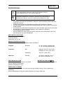
Contacts
If you encounter any problem with your recorder, please contact your nearest Sales Office. (See the
address list at the end of this manual).
An engineer will discuss your problem with you. Please have your complete model
number and serial number available. Model number and serial number are located on the
chassis nameplate.
If it is determined that a hardware problem exists, a replacement instrument or part will be shipped
with instructions for returning the defective unit. Do not return your instrument without authorization
from your Sales Office or until the replacement has been received.
World Wide Web: http://www.honeywell.com
Corporate Industrial Measurement and Control: http://www.honeywell.com/imc/
Telephone: USA & Canada Honeywell:
Technical Support:
TAC FACS:
Service:
1800-423-9883
1888-423-9883
1800-525-7439
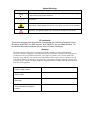
Symbol Meanings
Symbol
What it means
Protective ground terminal. Provided for connection of the protective earth green (green
or green/yellow) supply system conductor.
Functional ground terminal. Used for non-safety purposes such as noise immunity
improvement.
WARNING. Risk of electric shock. This symbol warns the user of a potential shock
hazard where voltages greater than 30 Vrms, 42.4 Vpeak, or 60 Vdc may be accessible.
CAUTION. When this symbol appears on the product, see the user manual for more
information. This symbol appears next to the required information in the manual.
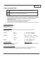
CE conformity
This product conforms with the protection requirements of the following European Council
Directives: 89/336/EEC, the EMC directive, and 73/23/EEC, the low voltage directive. Do
not assume this product conforms with any other “CE Mark” Directive(s).
Attention
The emission limits of EN 61326-1 are designed to provide reasonable protection against harmful
interference when this equipment is operated in an industrial environment. Operation of this equipment in a
residential area may cause harmful interference. This equipment generates, uses, and can radiate radio
frequency energy and may cause interference to radio and television reception when the equipment is used
closer than 30 meters to the antenna(e). In special cases, when highly susceptible apparatus is used in close
proximity, the user may have to employ additional mitigating measures to further reduce the electromagnetic
emissions of this equipment.
Product model number:
Serial number:
Date code:
Service department telephone
number:
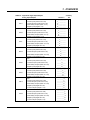
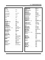
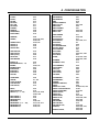
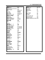
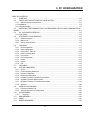
TABLE OF CONTENTS
TABLE OF CONTENTS
1.
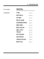
OVERVIEW ............................................................................................................................................... 1-1
1.1 RECORDER OVERVIEW .............................................................................................................. 1-2
1.2 MODEL SELECTION GUIDE ....................................................................................................... 1-4
2.
INSTALLATION ....................................................................................................................................... 2-1
2.1 WARNING ........................................................................................................................................ 2-2
2.2 UNPACKING .................................................................................................................................... 2-3
2.3 PANEL MOUNTING THE RECORDER ...................................................................................... 2-4
2.4 WIRING THE RECORDER............................................................................................................ 2-7
2.5 TERMINAL CONNECTIONS ........................................................................................................ 2-8
2.6 FITTING THE CHART ................................................................................................................. 2-15
2.7 INSTALLING THE PRINTING SYSTEM .................................................................................. 2-22
2.8 CHECK LIST.................................................................................................................................. 2-24
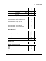
3.
OPERATION ............................................................................................................................................. 3-1
3.1 OPERATOR INTERFACE EXPLANATIONS ............................................................................. 3-2
3.2 OPERATOR INTERFACE.............................................................................................................. 3-2
3.3 POWER UP ....................................................................................................................................... 3-3
3.4 SELECTING AND INTERPRETING RUN MODE DISPLAY................................................... 3-4
3.5 OPERATOR INITIATED ACTIONS............................................................................................. 3-9
3.6 GLOSSARY OF OPERATING TERMS ...................................................................................... 3-12
4.
CONFIGURATION................................................................................................................................... 4-1
4.1 INTRODUCTION............................................................................................................................. 4-2
4.2 PARAMETERS LIST....................................................................................................................... 4-3
4.3 PRINCIPLES OF CONFIGURATION .......................................................................................... 4-4
4.4 COPY CONFIGURATION.......................................................................................................... 4-104
4.5 PRINT CONFIGURATION......................................................................................................... 4-108
4.6 CONFIGURABLE AND PRINTABLE CHARACTERS.......................................................... 4-114
INDEX............................................................................................................................................ 4-115
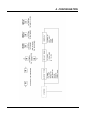
5. PC CONFIGURATION................................................................................................................... 5-1
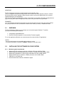
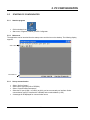
5.1 OVERVIEW ......................................................................................................................................5-2
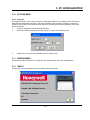
5.2 INSTALLING THE SOFTWARE ON YOUR SYSTEM..............................................................5-2
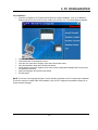
5.3 INSTALLING THE FIRMWARE FOR YOUR RECORDER OR FOR YOUR
COMMUNICATION BOARD .................................................................................................................5-4
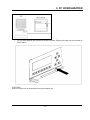
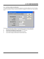
5.4 PC - RECORDER INTERFACE.....................................................................................................5-4
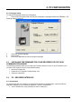
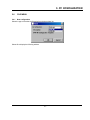
5.5 STARTING PC CONFIGURATOR ......................................................................................5-6
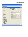
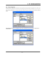
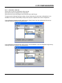
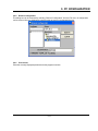
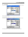
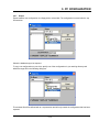
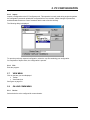
5.6 FILE MENU ......................................................................................................................................5-7
5.7 VIEW MENU ..................................................................................................................................5-14
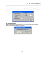
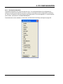
5.8 ON-LINE COMM MENU ..............................................................................................................5-14
5.9 USER ACTUATION MENU..........................................................................................................5-21
5.10 OPTIONS MENU............................................................................................................................5-23
i
TABLE OF CONTENTS
5.11 WINDOW MENU ..........................................................................................................................5-23
5.12 ABOUT ...........................................................................................................................................5-23
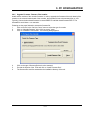
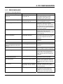
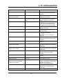
5.13 ERROR MESSAGES.....................................................................................................................5-24
6.
KITS LIST.................................................................................................................................................. 6-1
7.
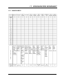
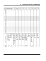
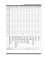
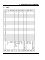
TROUBLESHOOTING ............................................................................................................................ 7-1
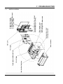
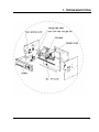
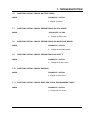
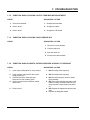
7.1 PARTS LOCATION......................................................................................................................... 7-2
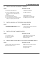
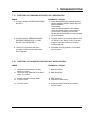
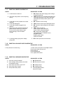
7.2 SYMPTOMS: .................................................................................................................................... 7-4
to 7.24........................................................................................................................................................ 7-10
8.
SERVICE.................................................................................................................................................... 8-1
8.1 OPERATOR INTERFACE.............................................................................................................. 8-2
8.2 LIST OF SERVICES ........................................................................................................................ 8-5
9.
PRODUCT SPECIFICATION ................................................................................................................. 9-1
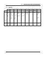
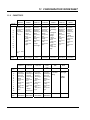
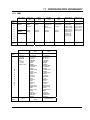
10. PROMPTS TRANSLATION ................................................................................................................. 10-1
10.1 MATRICES ..................................................................................................................................... 10-2
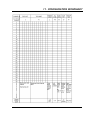
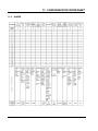
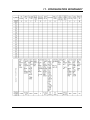
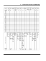
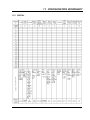
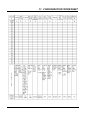
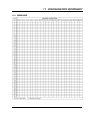
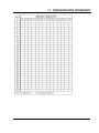
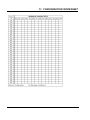
11. CONFIGURATION WORKSHEETS .................................................................................................. 11-1
to 11.13 ............................................................................................................................................................ 11-16
SAFETY TRANSLATIONS
SALES AND SERVICE
ii
1. OVERVIEW
TABLE OF CONTENTS
Section 1
1.1
RECORDER OVERVIEW . . . . . . . . . . . . . . . . . . . . . . . . . . . . . . . . . . . . . . . . . . . . . 1-2
1.1.1
INTRODUCTION . . . . . . . . . . . . . . . . . . . . . . . . . . . . . . . . . . . . . . . . . . . . . . 1-2
1.1.2
MODEL SELECTION GUIDE . . . . . . . . . . . . . . . . . . . . . . . . . . . . . . . . . . . . . 1-3
1-1
1. OVERVIEW
1.1
RECORDER OVERVIEW
1.1.1 INTRODUCTION
This recorder is a precision measuring instrument that offers many features.
•
•
•
•
•
•
•
•
•
•
•
Up to 64 analog input channels,
Compact size: 320 mm (12.60 '') depth,
310 mm front face height x 387 mm width (12.21 '' x 15.24 ''),
278 mm x 348 mm (10.95 '' x 13.70 '') cutout,
250 mm chart in either roll or fanfold presentation,
Universal power supply: 100 to 240 V ac/dc,
IP55 front panel protection,
Universal input with a wide choice of actuation/range,
Option linear input,
High accuracy: 0.05 % via field calibration,
Easy interactive product configuration,
Large, clear operator display,
Fast scanning rate:
2 channels = 105 ms
4 channels = 210 ms
8 channels = 420 ms
12 channels = 630 ms
16 channels = 840 ms
20 channels = 1050 ms
•
•
•
•
•
•
•
•
•
•
24 channels = 1260 ms
28 channels = 1470 ms
32 channels = 1680 ms
36 channels = 1890 ms
40 channels = 2100 ms
44 channels = 2310 ms
Configurable alphanumeric chart documentation,
Up to 64 alarm setpoints with a wide choice of alarm types,
Event alarm: End of chart paper, sensor burnout, clock battery low, etc.,
Up to 64 customer messages of 64 characters each,
Standard chart illumination,
Product configuration, service diagnostic, software upgrading via PC interface,
Chart zoning configurable,
Complies with IEC348 and EN61010-1 safety requirements,
EC mark: Conformity with 73/23/EEC low voltage directive and 89/336 EEC, EMC directives,
CSA approval (certified) LR57938
OPTIONS:
•
•
•
•
•
•
•
48 channels = 2520 ms
52 channels = 2730 ms
56 channels = 2940 ms
60 channels = 3150 ms
64 channels = 3360 ms
52 channels = 2730 ms
Up to 48 alarm relay outputs,
Up to 48 digital inputs,
Keylock,
32 Maths functions,
Communication board,
Up to 8 4/20 mA current outputs,
PCMCIA board driver.
1-2
1. OVERVIEW
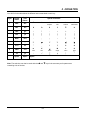
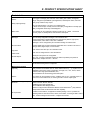
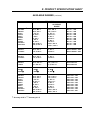
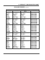
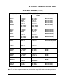
1.2
MODEL SELECTION GUIDE
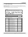
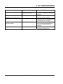
This table helps you to identify correctly the unit in front of you. Please refer to the product label and verify
that you have the right unit.
Select the desired key number. The mark to the right shows the selection available. A complete model
number has the requested number of digits from each table as follows:
Instructions
Select the desired Key Number. The arrow to the right marks the selection available.
A dot denotes unrestricted availability. A letter denotes restricted availability.
A complete Model Number must have the designated number of digits in each table.
Key Number
D25
I
-
V
____
II
________
VI
-
__
- ________
III
-
IV
___
-
_
-
VII
-
_
KEY NUMBER
Description
250 mm Strip Chart Recorder
D25
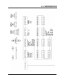
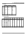
TABLE I - Lower Rack Analog Inputs
Input Card 1
None
(Slot A)
4 Linear Inputs (Channel 1 to 4)
Input Card 2
(Slot B)
4 Universal Inputs (Channel 1 to 4)
None
4 Linear Inputs (Channel 5 to 8)
Input Card 3
(Slot C)
4 Universal Inputs (Channel 5 to 8)
None
4 Linear Inputs (Channel 9 to 12)
Input Card 4
(Slot D)
4 Universal Inputs (Channel 9 to 12)
None
4 Linear Inputs (Channel 13 to 16)
Input Card 5
(Slot E)
4 Universal Inputs (Channel 13 to 16)
None
4 Linear Inputs (Channel 17 to 20)
Input Card 6
(Slot F)
4 Universal Inputs (Channel 17 to 20)
None
4 Linear Inputs (Channel 21 to 24)
Input Card 7
(Slot G)
4 Universal Inputs (Channel 21 to 24)
None
4 Linear Inputs (Channel 25 to 28)
Input Card 8
(Slot H)
4 Universal Inputs (Channel 25 to 28)
None
4 Linear Inputs (Channel 29 to 32)
4 Universal Inputs (Channel 29 to 32)
1-3
Selection
Availability
0_______
L_______
U_______
_0______
_L______
_U______
__0_____
__L_____
__U_____
___0____
___L____
___U____
____0___
____L___
____U___
_____0__
_____L__
_____U__
______0_
______L_
______U_
_______0
_______L
_______U
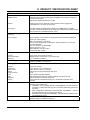
1. OVERVIEW
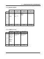
TABLE II - Upper Rack Digital Inputs/Outputs
Analog Inputs/Outputs
None
4 Linear Inputs (Channel 33 to 36)
Slot J
4 Universal Inputs (Channel 33 to 36)
6 Alarm Relay Outputs (Alarm 1 to 6)
Slot K
Slot L
Slot M
Slot N
Slot P
Slot Q
Slot R
6 Digital Inputs (Digital 1 to 6)
None
4 Linear Inputs (Channel 37 to 40)
4 Universal Inputs (Channel 37 to 40)
6 Alarm Relay Outputs (Alarm 7 to 12)
6 Digital Inputs (Digital 7 to 12)
None
4 Linear Inputs (Channel 41 to 44)
4 Universal Inputs (Channel 41 to 44)
6 Alarm Relay Outputs (Alarm 13 to 18)
Availability
Selection
0_______
L_______
U_______
A_______
D_______
_0______
_L______
_U______
_A______
_D______
6 Digital Inputs (Digital 13 to 18)
__0_____
__L_____
__U_____
__A_____
__D_____
None
___0____
4 Linear Inputs (Channel 45 to 48)
___L____
4 Universal Inputs (Channel 45 to 48)
___U____
6 Alarm Relay Outputs (Alarm 19 to 24)
___A____
6 Digital Inputs (Digital 19 to 24)
___D____
None
____0___
4 Linear Inputs (Channel 49 to 52)
____L___
4 Universal Inputs (Channel 49 to 52)
____U___
6 Alarm Relay Outputs (Alarm 25 to 30)
____A___
6 Digital Inputs (Digital 25 to 30)
None
4 Linear Inputs (Channel 53 to 56)
4 Universal Inputs (Channel 53 to 56)
6 Alarm Relay Outputs (Alarm 31 to 36)
____D___
6 Digital Inputs (Digital 31 to 36)
None
4 Linear Inputs (Channel 57 to 60)
4 Universal Inputs (Channel 57 to 60)
6 Alarm Relay Outputs (Alarm 37 to 42)
6 Digital Inputs (Digital 37 to 42)
4 Current Outputs (Output 1 to 4)
None
4 Linear Inputs (Channel 61 to64)
4 Universal Inputs (Channel 61 to 64)
6 Alarm Relay Outputs (Alarm 43 to 48)
6 Digital Inputs (Digital 43 to 48)
4 Current Outputs (Output 5 to 8)
1-4
_____0__
_____L__
_____U__
_____A__
_____D__
______0_
______L_
______U_
______A_
______D_
______C_
_______0
_______L
_______U
_______A
_______D
_______C
D25
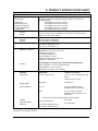
1. OVERVIEW
TABLE III - Options
Communications
PCMCIA
Math
None
Universal Communication
(RS232/422/485) ASCII/Modbus RTU
Ethernet Interface
None
PCMCIA Interface
(Note 6)
None
Math Package
Selection
0__
1__
D25
2__
_0_
_A_
__0
__A
d
TABLE IV - Door and Case Options
Grey Door, Glass Window, with Latch, Standard Case
Grey Door, Glass Window, with Key Lock, Standard Case
Grey Door, Plastic Window, with Latch, Standard Case
Grey Door, Plastic Window, with Key Lock, Standard Case
0
1
2
3
Grey Door, Glass Window, with Latch, Black Case
Grey Door, Glass Window, with Key Lock, Black Case
Grey Door, Plastic WIndow, with Latch, Black Case
Grey Door, Plastic Window, with Key Lock, Black Case
A
B
C
D
Black Door, Glass Window, with Latch, Black Case
Black Door, Glass Window, with Key Lock, Black Case
E
F
Grey Door, Plastic Window, Latch and Black Portable Case
4
TABLE V - Miscellaneous
None
None
Test Report (Calibration Certificate)
0___
(Note 5)
Certificate of Conformance
None
_0__
_A__
_B__
__0_
__A_
Product Configuration
Product Configuration with User Defined Actuation
(Note 3)
(Note 3)
User Defined Actuation
None
(Note 3)
__B_
__U_
CSA Approval/NRTL/C
(Note 4)
___0
___C
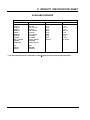
TABLE VI - Specials
None
Special ST # (Consult Ft. Washington)
00
XX
TABLE VII - Language/Prompts/Manuals
Product Information on CD
English
French
German
Italian Prompts/English Manual
Spanish
0
E
F
G
I
S
1-5
c
1. OVERVIEW
RESTRICTIONS
Restriction
Letter
Table
Available Only With
Selection
Table
c
V
d
II
Not Available With
Selection
___C
_ _ _ _ _ _ _ L, _ _ _ _ _ _ _ U,
_ _ _ _ _ _ _ A, _ _ _ _ _ _ _ D,
_______C
DPR 250
Notes:
1.
A 250 ohm resistor is required for ma input actuation's. Order the required
quantity using Part Number 46181080-503. See Parts Price Book for pricing.
2.
Consult Customer Services for pricing and availability.
3.
Customer must complete "Configuration Worksheets" and attach to order or
send to Customer Service. (Reference Product Manual)
4.
NRTL/C indicates product safety compliance approval by a Nationally Recognized
Testing Laboratory of which UL and CSA are both OSHA accredited NRTL's.
Not available with Portable Case option.
5.
It is recommended that the Product Configuration (Table V) option be ordered
when ordering the Calibration Certificate otherwise the certificate will be based
on the factory default configuration.
6.
PCMCIA Flash Memory Cards must be ordered separately.
PCMCIA Memory Cards are ATA Type II compatible and stored data is
accessible using SDA software (P/N 045501) or TrendManager Pro V5, TMPCON5.
1-6
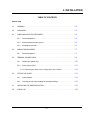
2. INSTALLATION
TABLE OF CONTENTS
Section Page
2.1
WARNING . . . . . . . . . . . . . . . . . . . . . . . . . . . . . . . . . . . . . . . . . . . . . . . . . . . . . . . . 2-2
2.2
UNPACKING . . . . . . . . . . . . . . . . . . . . . . . . . . . . . . . . . . . . . . . . . . . . . . . . . . . . . . 2-3
2.3
PANEL MOUNTING THE RECORDER . . . . . . . . . . . . . . . . . . . . . . . . . . . . . . . . . . . 2-4
2.4
2.3.1
Recommendations . . . . . . . . . . . . . . . . . . . . . . . . . . . . . . . . . . . . . . . . . . . . 2-4
2.3.2
External dimensions and cut-out . . . . . . . . . . . . . . . . . . . . . . . . . . . . . . . . . . 2-4
2.3.3
Installing the recorder . . . . . . . . . . . . . . . . . . . . . . . . . . . . . . . . . . . . . . . . .
2-5
WIRING THE RECORDER . . . . . . . . . . . . . . . . . . . . . . . . . . . . . . . . . . . . . . . . . . .
2-7
Recommendations . . . . . . . . . . . . . . . . . . . . . . . . . . . . . . . . . . . .. . . . . . . .
2-7
TERMINAL CONNECTIONS . . . . . . . . . . . . . . . . . . . . . . . . . . . . . . . . . . . . . . . . . .
2-8
2.4.1
2.5
2.5.1
Digital input signals. (DI). . . . . . . . . . . . . . . . . . . . . . . . . . . . ... . .. . . . . . . .
2-10
2.5.2
Relay outputs. (DO). . . . . . . . . . . . . . . . . . . . . . . . . . . . . . .. . . . . . .. . . . . .
2-11
2.5.2.1 Removing the alarm card to change NC to NO contacts . . . . . .. . . . . .. . . 2-12
2.6
FITTING THE CHART . . . . . . . . . . . . . . . . . . . . .. . . . . . . . . . . . . . . . . . . . . . . . . . . 2-15
2.6.1
Chart cassette . . . . . . . . . . . . . . . . . . . . . . . . . . . . . . . . . . . . . . . . . . . . . . . 2-16
2.6.2
Cleaning the rod and lubricating the carriage bushings. . . . . . . . . . . . . . . . . . 2-21
2.7
INSTALLING THE PRINTING SYSTEM . . . . . . . . . . . . . .. . . . . . . . . . . . . . . . . . . .
2-22
2.8
CHECK LIST . . . . .. . . . . . . . . . . . . . . . . . . . . . . . . . . . . . . . . . . . . . . . . . . . . . . . .
2-24
2-1
2. INSTALLATION
2.1
WARNING
WARNING
IMPROPER INSTALLATION
!
To avoid the risk of electrical shock that could cause personal injury, follow all safety notices in
this documentation.
Protective earth terminal. Provided for connection of the protective earth supply system
conductor.
Failure to comply with these instructions could result in death or serious injury
! POWER SUPPLY
Ensure the source voltage matches the voltage of the power supply before turning on the power. (In the
rear of the recorder, near to the connector of the power supply)
! PROTECTIVE GROUNDING
Make sure to connect the protective grounding to prevent an electric shock before turning on the power.
Do not operate the instrument when protective grounding or fuse might be defective.
To avoid a potential shock hazard, never cut off the internal or external grounding wire or disconnect the
protective grounding terminal
! NECESSITY OF PROTECTIVE GROUNDING
To avoid a potential shock hazard, never cut off the internal or external protective grounding wire or
disconnect the wiring of protective grounding terminal.
! FUSE
To prevent a fire, make sure to use the fuse with specified standard (current voltage, type). Before
replacing the fuse, turn off the power and disconnect the power source. Do not use a different fuse or
short-circuit the fuse holder.
! DO NOT OPERATE IN AN EXPLOSIVE ATMOSPHERE
Do not operate the instrument in the presence of flammable liquids or vapours. Operation of any
electrical instrument in such an environment constitutes a safety hazard.
! NEVER TOUCH THE INTERIOR OF THE INSTRUMENT
Inside this instrument there are areas of high voltage; therefore, never touch the interior if the power
supply is connected. This instrument has an internal changeable system; however, internal inspection
and adjustments should be performed by qualified personnel only.
! If the equipment is used in a manner not specified by the manufacturer, the protection provided by the
equipment may be impaired.
! Do not replace any component (or part) not explicitly specified as replaceable by your supplier.
! INSTALL INDOOR ONLY
2-2
2. INSTALLATION
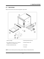
2.2
UNPACKING
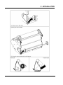
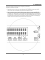
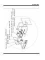
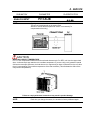
Remove the accessories and check them against the figure below.
1. Ribbon cartridge
4. Mounting brackets with nuts
2. Fuse (Spare) (Use only 3.15 A T. fuses for
Europe or 3.2 A T. fuses for U.S.)
5. Product manual or CD
3. Roll (R) and fanfold (Z) chart
6. Front label
7. Recorder
NOTE: In the event that any items are missing, please contact your nearest sales office.
2-3
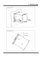
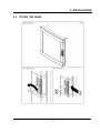
2. INSTALLATION
2.3
PANEL MOUNTING THE RECORDER
2.3.1 Recommendations
This recorder is designed to operate under specific conditions. If you need more information, refer to the
product specification sheet.
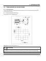
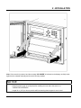
2.3.2 External dimensions and cut-out
Prepare panel cut-out as detailed below:
Note: Maximum panel thickness 40 mm (1.5 '')
!
CAUTION
The maximum temperature inside the cabinet should not exceed the ambient conditions specific for the
recorders. The recorder must be mounted into a panel to limit operator access to the rear terminals.
Failure to comply with these instructions may result in product damage
2-4
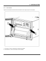
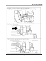
2. INSTALLATION
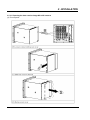
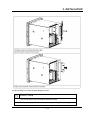
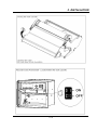
2.3.3
Installing the recorder
To install the recorder, follow the figures below:
1. Remove rear cover and wire access holes.
2. Insert recorder through the panel cutout
3. Attach mounting brackets to the sides of the recorder
4. Tighten the mounting screws
2-5
2. INSTALLATION
2-6
2. INSTALLATION
2.4
WIRING THE RECORDER
2.4.1
Recommendations
•
All wiring must be in accordance with local electrical codes and should be carried out by
authorized experienced personnel.
•
The ground terminal must be connected before any other wiring (and disconnected
last).
•
A switch in the main supply is recommended near the equipment.
•
If an external fuse is used to protect the electrical circuit to the recorder, the fuse
should match the recorder fuse rating (fuse type) as well as for the fuse holder.
•
Sensor wiring should be run as far as possible from power wiring. (motors, contactors,
alarms, etc.)
•
To reduce stray pick-up, we recommend the use of a twisted pair sensor wiring.
•
EMI effects can be further reduced by the use of shielded cable sensor wiring. The
shield must be connected to the ground terminal.
•
The use of spade terminals on all wiring is recommended.
2-7
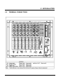
2. INSTALLATION
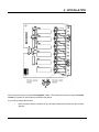
2.5
TERMINAL CONNECTIONS
2-8
2. INSTALLATION
Note: Terminal (A) is only used for RTD. (See diagrams above)
!
CAUTION
Unwired configured channel terminals should be shorted.
Failure to comply with these instructions may result in product damage
2-9
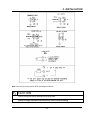
2. INSTALLATION
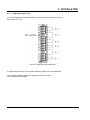
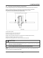
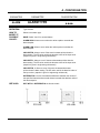
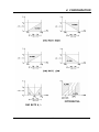
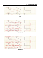
2.5.1
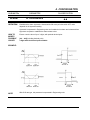
Digital input signals. (DI)
If an optional digital input board is installed, connect the wiring as shown in Figure 2-1.
Slot location X = J to P
Figure 2-1 Digital input signal wiring (DI)
If 2 digital input boards are fitted, repeat the above procedure for the second board.
Note: Use dry contacts, voltage free, designed to switch 5 mA at 5 V.
Up to 36 digital inputs allowed.
2-10
2. INSTALLATION
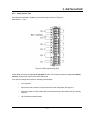
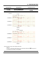
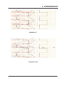
2.5.2
Relay outputs. (DO)
If an optional relay board is installed, connect the wiring as shown in Figure 2-2.
Slot location X = J to P
Figure 2-2 Relay output wiring (DO)
All the relays are factory configured de-energized in alarm. The contacts are factory configured normally
closed by a jumper per output on the alarm relay board.
If you need to change this function for normally opened output:
•
Turn off power.
•
Remove the rear terminal cover plate and remove the relay board, see page 2-11.
•
Move the jumper from the location NC (for normally closed) to the location NO (for normally
opened).
•
Up to 36 alarm outputs allowed.
2-11
2. INSTALLATION
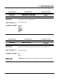
2.5.2.1 Removing the alarm card to change NC to NO contacts
(A) Turn off power.
2-12
2. INSTALLATION
Use ground strap to avoid electrostatic damage to board.
!
CAUTION
Use ground strap to avoid electrostatic damage to board.
Failure to comply with these instructions may result in product damage
2-13
2. INSTALLATION
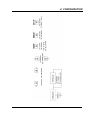
All the relays are factory configured de-energized in alarm. The contacts are factory configured normally
closed by a jumper for each output on the alarm relay board.
If you need to change this function:
•
Move the jumper from the location NC (for normally closed) to the location NO (for normally
opened)
2-14
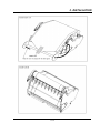
2. INSTALLATION
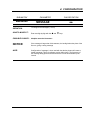
2.6
FITTING THE CHART
2-15
2. INSTALLATION
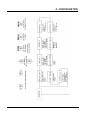
2.6.1
Chart cassette
Open the chart cassette as shown below and install the chart using the figure on the cassette.
1 = First action - Press in on both tabs to release chart cassette
2 = Second action - Pull out on the tabs to remove cassette
2-16
2. INSTALLATION
2-17
2. INSTALLATION
2-18
2. INSTALLATION
2-19
2. INSTALLATION
Note: If the recorder is powered, and the message "NO PAPER" is indicated on the display, carefully check
again that the cassette assembly and chart are correctly installed.
NOTICE
Reset the paper length (if configured) after installing the new chart. See section 3.2
"OPERATOR INTERFACE".
Length 35 m (115 ft) or less to provide sufficient warning that the paper is near its end.
2-20
2. INSTALLATION
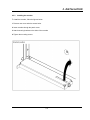
2.6.2 Cleaning the rod and lubricating the carriage bushings
The print carriage bushings are factory lubricated and should not normally require further maintenance.
However, in a dusty environment, you should have to clean the print carriage rod periodically.
Also, whenever the print carriage rod is found sticky or dirty, you have to clean it.
The procedure for cleaning and lubricating is explained below:
1. Power off the recorder.
2. Clean the rod with a dry, lint free cotton cloth.
3. Move the carriage to the center of the rod.
4. Apply a thin ring of grease around the rod, at each side of the carriage (as shown above).
5. Move the carriage from right to left four or five times.
6. Wipe off any excess grease from the rod with a dry, lint free cotton cloth.
! CAUTION
Never use any solvent to clean the rod.
Please, use only lubricant "Dow Corning white EP grease or equivalent" which may be ordered as
part number: "Lubricant kit 46210096-501".
Failure to comply with these instructions may result in product damage
NOTE:
The color ribbon axis (50 mm long), which keeps maintained the color ribbon, must be cleaned with a dry
cotton cloth each time you replace the color ribbon.
2-21
2. INSTALLATION
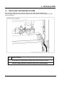
2.7
INSTALLING THE PRINTING SYSTEM
Before doing it, please remove the chart cassette from the chassis as indicated page 2-15.
The recorder automatically moves the print carriage to the correct position for the installation of the ink
ribbon cartridge by:
!
CAUTION
Do not attempt to install the ribbon cartridge while the chart cassette is in place.
Failure to comply with these instructions may result in product damage
2-22
2. INSTALLATION
2-23
2. INSTALLATION
2.8
CHECK LIST
Your recorder should now be ready to configure and use. If you are having problems check the
following
1. Have you connected the ground terminal ?
2. Have you connected the sensor(s) correctly? (Wire type, polarity, etc.)
3. Have you tightened all terminal screws?
4. Have you installed the ink ribbon cartridge? (See figures on page 2-22)
5. Have you installed the chart correctly? (See figures on page 2-15)
6. Have you closed the display?
7. Have you fitted the chart cassette in the recorder?
8. Have you replaced the rear cover?
9. Have you switched ON the power switch?
2-24
3. OPERATION
TABLE OF CONTENTS
Section Page
3.1
OPERATOR INTERFACE EXPLANATION . . . . . . . . . . . . . . . . . . . . . . . . . . . . . . .
3-2
3.2
OPERATOR INTERFACE . . . . . . . . . . . . . . . . . . . . . . . . . . . . . . . . . . . . . . . . . . .
3-2
3.3
POWER UP . . . . . . . . . . . . . . . . . . . . . . . . . . . . . . . . . . . . . . . . . . . . . . . . . . . . .
3-5
Power up display sequence . . . . . . . . . . . . . . . . . . . . . . . . . . . . . . . . . . . .
3-5
3.3.1
3.3.1.1 Display test. . .
.......................................
3.3.1.2 Measure initialization
3.4
.....................................
3-6
3.4.1 INTRODUCTION . . . . . . . . . . . . . . . . . . . . . . . . . . . . . . . . . . . . . . . . . . . . .
3-6
3.4.2 How to select a display type . . . . . . . . . . . . . . . . . . . . . . . . . . . . . . . . . . . . .
3-6
3.4.3 How to explain displays in run mode. . . . . . . . . . . . . . . . . . . . . . . . . . . . . . . .
3-7
. . . . . . 3-7
3.4.3.2 Exception: For selections on the 2 displays with the same display type.
3.4.3.3 LOCK displays
3.6
3-5
SELECTING AND INTERPRETING RUN MODE DISPLAY. . . . . . . . . . . . . . . . . . . .
3.4.3.1 For a selection either on the upper display and/or on the lower display
3.5
3-5
.....
3-9
. . . . . . . . . . . . . . . . . . . . . . . . . . . . . . . . . . . .. . . . . .
3-9
OPERATOR INITIATED ACTIONS . . . . . . . . . . . . . . . . . . . . . . . . . . . . . . . . . . . . .
3-11
3.5.1 Hold display . . . . . . . . . . . . . . . . . . . . . . . . . . . . . . . . . . . . . . . . . . . . . . . . .
3-11
3.5.2 Printer action . . . . . . . . . . . . . . . . . . . . . . . . . . . . . . . . . . . . . . . . . . . . . . . .
3-12
3.5.3 RESET display . . . . . . . . . . . . . . . . . . . . . . . . . . . . . . . . . . . . . . . . . . . . . . .
3-13
3.5.4 Alarm acknowledgment . . . . . . . . . . . . . . . . . . . . . . . . . . . . . . . . . . . . . . . . .
3-13
GLOSSARY OF OPERATING DISPLAY MESSAGES . . . . . . . . . . . . . . . . . . . . . . .
3-14
3-1
3. OPERATION
OPERATOR INTERFACE EXPLANATION
3.1
This section describes the various actions which an operator can initiate through the keyboard, and explains
how to interpret the displays in the different modes of operation available.
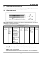
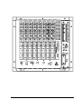
3.2
OPERATOR INTERFACE
DISPLAY AND KEYPAD: The display gives a clear indication of action prompts by means of two lines of 16
characters and the keypad consists of 23 keys.
•
7 function keys that enable you to start immediate action. See table below.
FUNCTION KEYS
F1
HOLD
PRINT
RESET
Immediate
action key
configurable
To hold the
display on a
current
channel.
To choose an
Immediate printing
action.
The choices are:
- Inhibit/Printing
- Reset paper length
- Change speed/ int 2
to speed/ int 1
- Print date & time
- Snap shot trace
- Chart advance
- Change group B to
A
- Change group A+B
to B
- Snap shot logic
- Snap shot math
- Start archive/stop
archive
- Remove PCMCIA
- Math
- Occurrence
- Reset
PCMCIA
Use !and
"keys to
change the
channel.
ACK
To
Acknowledge
all latching
alarm relays
DISPLAY
F2
To choose the
display type in
run mode or to
escape
from
configuration
to run mode
Immediate
action key
configurable
NOTE: The function keys are used in run mode and they control the contents of the display and other
functions. In case of a power loss the configuration is unchanged.
•
•
#$!"
: THESE KEYS ARE USED FOR PRODUCT CONFIGURATION.
SET UP: To move to configuration mode or to return from parameter configuration to the sub-
matrix.
•
•
ENTER: To confirm your selected action.
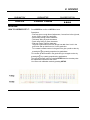
An ALPHANUMERIC keypad with either capital and small print letters, digits or special characters.
3-2
3. OPERATION
The keypad is designed to simplify the way to configure your parameters.
Two kinds of parameters are possible:
1.
Parameters in which you only have to enter digits (eg: CHART SPEED) or to enter a letter (COPY
function). Both cases, the keyboard will automatically be configured correctly.
2.
Parameters which need every possible ASCII characters defined in the recorder (eg: MESSAGE).
When you confirm the action to enter configuration mode, a triangle in the right hand bottom corner of
your display is lit. It indicates that you are in capital letter mode. Depending on the type of characters
you wish to enter, you will have to press the F2 key. Then it will automatically shift to the next group of
characters (digits, small print letters, special characters, capital letters) indicated on the display by a
triangle. Then you will be able to select the way you wish to write the text.
3-3
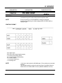
3. OPERATION
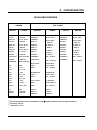
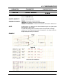
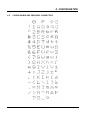
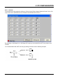
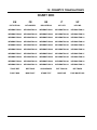
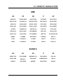
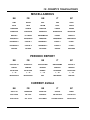
You will find in the table below the different letters associated to each key:
Digits
Capital
letters
Small
print
letters
1
ABC
abc
Ω
°
DEF
def
Ä
GHI
ghi
JKL
2
3
4
5
6
7
8
9
0,-
Special characters
A
V
C
F
Ampere
Volt
Celsius
Fahrenheit
Ö
Ü
ñ
Ñ
Å
/
*
-
+
±
.
jkl
[
]
(
)
{
}
MNO
mno
.
,
;
:
!
?
PQR
pqr
=
≠
<
>
≤
≥
STU
stu
"
_
#
$
%
&
VWX
vwx
YZ
yz
Space
Space
µ
m
K
M
n
G
milli
kilo
micro
mega
nano
giga
\
√
∑
φ
∫
ˆ
Space
Note: The selection can also be made with the ! and " keys in the same way as for parameters
containing a list of choices.
3-4
3. OPERATION
3.3
POWER UP
WARNING
!
Before powering up, check your recorder is correctly installed. See section 2, "INSTALLATION".
Failure to comply with these instructions could result in death or serious injury
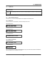
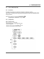
3.3.1 Power up display sequence
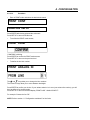
After powering up, check the messages appear on the displays in the following order:
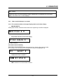
3.3.1.1 Display test
Check that all dots for each character, commas and triangle marks are lit.
Upper display shows:
INITIALIZATION
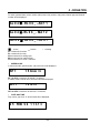
If the communication board is present,
Upper display shows:
INITIALIZATION
Lower display shows:
COMMUNICATION
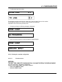
3.3.1.2 Measure initialization
Upper display shows:
INITIALIZATION
Lower display shows:
MEASURE
During a few seconds, the recorder reads and analyzes every inputs. After these operations of initialization,
input values appear on the 2 displays in run mode.
3-5
3. OPERATION
3.4
SELECTING AND INTERPRETING RUN MODE DISPLAY
3.4.1 INTRODUCTION
The recorder allows you to choose between a lot of display types when in the normal scanning mode. At the
end of the power display sequence (see section 3-5, "POWER UP"), the display will be in the scanning
mode, in the display type you have selected in the configuration matrix of the display (Parameters: DISPLAY
HI, DISPLAY LO).
To select another display type (for the lower and/or the upper display), use the DISPLAY key (See next
section 3.4.2 ) or use the configuration mode.
3.4.2
How to select a display type
•
The immediate action keys are not available if you are in configuration mode.
•
The selection of the DISPLAY key is lost at the power off.
•
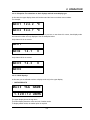
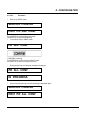
Press the DISPLAY key. Then you can read:
DISPLAY HI
The upper display is flashing.
DISPLAY LO
•
The ! and "
the ENTER key.
keys allow you to select the desired display. Confirm your choice by pressing
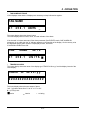
According to your choice, you may obtain:
DISPLAY HI
ANALOG INPUTS
Electrical input signal
or
DISPLAY LO
ANALOG INPUTS
•
The !
and "
Electrical input signal
keys allow you to select the desired display mode on the lower display.
3-6
3. OPERATION
NOTICE
In particular cases, you may be allowed to select a display type or a parameter only in the upper
display. See section 3.4.3.3, "LOCK displays".
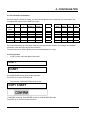
3.4.3
How to explain displays in run mode
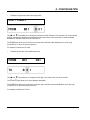
3.4.3.1 For a selection either on the upper display and/or on the lower display
ANALOG INPUTS
•
Analog input numbers, measured values and sensor engineering units will be displayed.
AN 0 1 1 2 4 . 2 o C
AN = mnemonic for analog input
•
Two printed channels on the same display
0124.2&24.3
01: channel number
24.2: channel value of channel 1
24.3: channel value of channel 2
Note that the second channel number is incremented by 1 from the first channel number.
If, for example, the first channel is not configured, no value will be displayed, e.g.
03
•
&247.2
COMMUNICATION CHANNELS
COM 0 1 2 5 4 . 9
•
COM = mnemonic for communication channel
3-7
3. OPERATION
•
ALARMS
For each operated alarm, alarm number, alarm state, relay number, relay state, channel type and channel
number will be displayed.
AL 0 4 " - RL 0 6 _ - AN 1 1
AL 0 4 "- RL 0 6 _ - MA 1 2
AL 0 4 "- RL 0 6 _ - CO 0 1
"
_
active
inactive
AL = mnemonic for alarm
RL = mnemonic for relay
AN = mnemonic for analog input
MA = mnemonic for maths results
CO = mnemonic for comm. Channels
. = missing
SPEED IN USE
In the trend mode, speed number, value and unit will be displayed.
•
SP 1
1 5 0mm / h
SP 1 or SP 2 = mnemonic for speed 1 or speed 2
In tabular mode, interval name, time and unit will be displayed.
INT 1
10min
INT1 or INT2 = mnemonic for interval 1 or interval 2
•
DATE AND TIME
Day, month, year, hour "h" and minutes will be displayed.
2 5 FEB 9 6 1 1 h 1 3
3-8
3. OPERATION
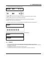
3.4.3.2 Exception: For selections on the 2 displays with the same display type
In this case the upper display shows odd numbers and the lower one shows even numbers.
For example:
AN 0 1
124.2
o
AN 0 2
544.7
o
C
C
If a channel is not configured or does not exist, when previous or next channel is correct, then display mode
and channel number are only displayed. See the examples below:
Only channel 01 is not correct:
AN 0 1
AN 02
14.1
o
C
Only channel 06 is not correct:
AN 0 5
74.3
o
C
AN 0 6
3.4.3.3 LOCK displays
In this case you are allowed to select a display mode only in the upper display.
•
MATHS RESULTS
MA 2 0
TAG
NAME
1 . 3 2 E + 1 2 UNITS
The upper display shows the tag name
The lower display shows the value and unit of maths results.
To display maths results, the maths option is required
3-9
3. OPERATION
TAG NAME AND TRACE
LOCK displays mean that the 2 displays are necessary to keep information together.
•
TAG NAME
01
258.1
UNITS
_
The upper display shows the channel name.
The lower display shows number, value, unit and indicator of the alarm.
If the channel is in alarm status and if the alarm parameter (See EVENTS matrix, ONE ALARM ON
parameter) is not valid, then the "A" indicator appears on the last digit of the display. On the contrary units
are displayed and the alarm number is displayed just after, as follows
If ALARM and EVENTS are ON:
TAG
01
NAME
258.1
AL 1 2
UNITS "
TRACES IN ALARM
The upper display shows the name of the display type "TRACE IN ALxx-yy" and the display interval of the
lower display.
•
TRACE
IN
AL x x - y y
################
The lower display shows the trace status of alarm.
"xx" - "yy" takes values from "01 to 16" or "17 to 24".
# = you may have:
" active
_ inactive
. = missing
3-10
3. OPERATION
LOGICAL INPUT STATUS
The 2 displays are necessary.
•
DI
XX - - - >
YY
################
The upper display shows the name of the display type "DI" and the display interval of the lower display.
The lower display shows the digital input status.
"xx" - "yy" takes values from "01 to 16" or "17 to 24".
# = you may have:
" contact closed
_ contact opened
3.5
OPERATOR INITIATED ACTIONS
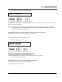
3.5.1
Hold display
. = missing
The HOLD key allows you to stop the scanning action while displaying current value of the selected channel
(upper display only).
The selection of the HOLD key is lost at the power off.
In case of locked displays, see section 3.4.3.3, "LOCK displays".
Then press HOLD key, the HOLD message appears on the upper display during a few seconds. And the
current value is displayed with two lit triangle marks, as shown below:
HOLD
01
"
245.5
UNITS
"
These two triangle marks allow you to scan the other channels.
NOTE: Some display types do not allow you to use the HOLD key, like DATE/TIME, SPEED.
3-11
3. OPERATION
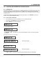
3.5.2
Printer action
The PRINT key allows you to choose between various actions.
Press PRINT key and the upper display shows during a few seconds:
BASIC ACTION
and just after:
PRINT MENU
INHIBIT
or
PRINTING
or
SPEED / INT 1
RESET PAPER LENG
SPEED / INT 2
PRINT DATE & TIME
SNAP SHOT TRACE
CHART ADVANCE
The chart advances as long as the
ENTER key is pressed.
CHG GROUP B
or
CHG GROUP A
CHG GROUP A + B
or
CHG GROUP B
SNAP SHOT LOGIC
3-12
3. OPERATION
SNAP SHOT MATH
START ARCHIVE
or
REMOVE PCMCIA
Press ENTER and use !
3.5.3
or
"
STOP ARCHIVE
Only when PCMCIA option is installed.
to choose the display type.
RESET display
Only when MATH OPTION is configured.
RESET MATH #
RESET ALL MATHS
RESET OCCURRENCE
RESET ALL OCCUR
RESET PCMCIA
3.5.4
Only when PCMCIA option is installed.
Alarm acknowledgment
Pressing ACK key is only allowed for alarms you have configured in acknowledgment mode.
This acknowledgment is only available
•
f the lower display shows alternately:
REQUEST ACK NOW
and the display type,
- if the ACK key is active.
(See ACK KEY parameter in the MMI sub-matrix)
3-13
3. OPERATION
3.6
•
GLOSSARY OF OPERATING DISPLAY MESSAGES
ENTERING IN THE IMMEDIATE ACTION MODE
BASIC ACTION
•
DISPLAY CHOICE
DISPLAY HI
DISPLAY LO
•
DISPLAY MODE CHOICE
ANALOG INPUTS
Electrical input signal
2 PVS TRACE
Process value in engineering unit
MATH RESULTS
Only when MATH OPTION is configured.
COMM RESULTS
Only when COMM OPTION is configured.
ALARM STATUS
SPEED IN USE
3-14
3. OPERATION
DATE & TIME
TRACE & TAG
TRACE IN ALARM
LOGIC STATES
•
ACK MESSAGES
REQUEST ACKNOW
ACKNOWLEDGMENT
•
INFORMATION MESSAGES
NO PAPER
END PAPER
BATTERY FAIL
ONE ALARM ON
BURNOUT
PRT INHIBIT
3-15
3. OPERATION
OVER FLOW SPEED
SHED TIME
Only when COMM option is configured.
PCMCIA FULL
PCMCIA BAD
PCMCIA NOT INIT
Only when PCMCIA option is configured.
PCMCIA PENDING
REMOVE PCMCIA
•
Diagnostic Messages
BAD CARRIAGE DISP
BAD REFERENCE
BAD EEPROM BACKPLANE
3-16
4. CONFIGURATION
TABLE OF CONTENTS
Section Page
4.1
INTRODUCTION . . . . . . . . . . . . . . . . . . . . . . . . . . . . . . . . . . . . . . . . . . . . . . . . . .
4-2
4.2
PARAMETERS LIST . . . . . . . . . . . . . . . . . . . . . . . . . . . . . . . . . . . . . . . . . . . . . . .
4-4
4.3
PRINCIPLE OF CONFIGURATION . . . . . . . . . . . . . . . . . . . . . . . . . . . . . . . . . . . .
4-5
4.4
COPY CONFIGURATION . . . . . . . . . . . . . . . . . . . . . . . . . . . . . . . . . . . . . . . . . . .
4.4.1 Introduction . . . . . . . . . . . . . . . . . . . . . . . . . . . . . . . . . . . . . . . . . . . . . . . . .
4.4.2 Configuration . . . . . . . . . . . . . . . . . . . . . . . . . . . . . . . . . . . . . . . . . . . . . . . .
4.4.3 WARNING . . . . . . . . . . . . . . . . . . . . . . . . . . . . . . . . . . . . . . . . . . . . . . . . . .
4-105
4-105
4-105
4-109
4.5
PRINT CONFIGURATION . . . . . . . . . . . . . . . . . . . . . . . . . . . . . . . . . . . . . . . . . . .
4.5.1 Introduction . . . . . . . . . . . . . . . . . . . . . . . . . . . . . . . . . . . . . . . . . . . . . . . . .
4.5.2 Configuration . . . . . . . . . . . . . . . . . . . . . . . . . . . . . . . . . . . . . . . . . . . . . . . .
4.5.3 Information about printing . . . . . . . . . . . . . . . . . . . . . . . . . . . . . . . . . . . . . . .
4.5.4 WARNING . . . . . . . . . . . . . . . . . . . . . . . . . . . . . . . . . . . . . . . . . . . . . . . . . .
4-110
4-110
4-111
4-115
4-115
4.6
CONFIGURABLE AND PRINTABLE CHARACTERS . . . . . . . . . . . . . . . . . . . . . . . .
4-116
INDEX . . . . . . . . . . . . . . . . . . . . . . . . . . . . . . . . . . . . . . . . . . . . . . . . . . . . . . . . . .
4-117
4-1
4. CONFIGURATION
4.1
INTRODUCTION
The recorder can be configured - using the front keyboard or by using the PC configurator and L.P.C.S.
When using the keyboard there are two possible levels of password that can be configured. Password 1
provides limited configuration access as shown on the configuration sheet (See page 4-92). Password 2
provides full configuration of all parameters (See page 4-93).
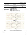
Page 4-1 provides a key to each explanation for the individual parameters.
To begin configuration you only need to press SET UP. The recorder will indicate "CONFIGURATION", "
ACCESS" and wait for a password to be entered if one has been programmed. If no password has been
programmed the recorder will display the "READ/WRITE", "ANALOG INPUT" position (see programming
matrix). You can now use the LEFT or RIGHT side arrows to select the sub-matrix you want to configure
(i.e. ANALOG INPUT, CHART, ALARM etc.) or the UP or DOWN arrows to select the READ/WRITE,
COPY, PRINT CONF or SERVICE matrices and then use the LEFT or RIGHT arrow to enter into one of
these sub-matrices. When you have selected the sub-matrix that you want to configure you only need to
press ENTER to begin configuration of this sub-matrix.
Each sub-matrix such as ANALOG INPUT has a number of parameters associated with it that need to be
configured in order to set up that parameter and channel. Each parameter needs to be configured for each
input. To exit from the configuration mode press DISPLAY or SET UP keys.
4-2
4. CONFIGURATION
SUB-MATRIX
NAME OF THE
FUNCTION
PARAMETER
NAME OF THE
PARAMETER
CLASSIFICATION
IMPORTANCE OF THE PARAMETER
! CAN BE CHANGED IN RUN MODE
!! STOP OF ACQUISITIONS
! WITH PASSWORD 1 OR 2
!! ONLY WITH PASSWORD 2
DEFINITION:
EXPLAIN THE ROLE OF THE PARAMETER
HOW TO MODIFY IT:
BY SELECTING OR ENTERING A NEW VALUE I.E. USING
THE ! # KEYS
POSSIBLE VALUES:
LIST OF POSSIBLE VALUES OR LIMITS
SEE ALSO:
EXAMPLE:
NOTE:
NOTICE
The configuration of parameters with the classification “!!“ stops the
acquisition as well as the operation of alarm supervision.
Leaving the configuration mode resets the memory buffer and the alarm status
is defined again, and the chart speed changes back to the configured value.
Occurrence value is reset.
4-3
4. CONFIGURATION
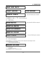
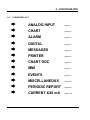
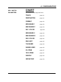
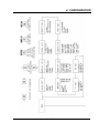
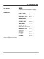
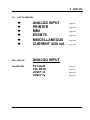
4.2
PARAMETERS LIST
$
$
$
$
$
$
$
$
$
$
$
$
ANALOG INPUT
page 4-6
CHART
page 4-20
ALARM
page 4-31
DIGITAL
page 4-47
MESSAGES
page 4-57
PRINTER
page 4-60
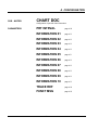
CHART DOC
page 4-69
MMI
page 4-77
EVENTS
page 4-84
MISCELLANEOUS
page 4-88
PERIODIC REPORT
page 4-96
CURRENT 4/20 mA
page 4-102
4-4
4. CONFIGURATION
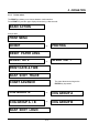
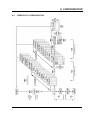
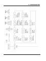
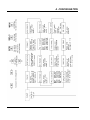
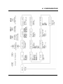
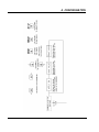
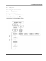
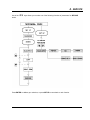
4.3
PRINCIPLE OF CONFIGURATION
4-5
4. CONFIGURATION
4-6
4. CONFIGURATION
SUB - MATRIX
ANALOG INPUT
Configuration of analog input parameters
PARAMETERS
SENSOR
page 4-7
RANGE
page 4-12
EXT COMP
page 4-13
FILTER
page 4-14
LOW VALUE
page 4-15
HIGH VALUE
page 4-15
STD MATH
page 4-16
DIFF WITH
page 4-17
BURNOUT
page 4-18
LOW ADJUST
page 4-19
HIGH ADJUST
page 4-19
4-7
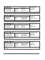
4. CONFIGURATION
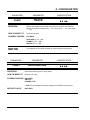
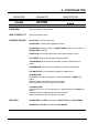
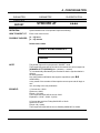
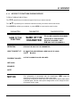
SUB-MATRIX
PARAMETER
CLASSIFICATION
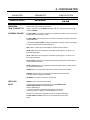
ANALOG INPUT
SENSOR
!! !!
DEFINITION:
HOW TO MODIFY IT:
Basic: sensor type used on each channel.
POSSIBLE VALUES:
T/C INT COMP: The sensor is a directly connected thermocouple and the cold junction
compensation of the recorder is used.
Select a new sensor. Press ENTER. With keys #
and press ENTER
!
select the right sensor type
T/C EXT COMP: Thermocouple sensor is directly connected to a remote temperature
compensation box *.
* See parameter EXT COMP to configure temperature or analog channels (see page 414) used to measure the external cold junction.
RTD: Sensor is a directly connected RTD or variable resistance device.
TR NL 0-5V: Sensor is a temperature transmitter signal range of 0-5V which is not
linear with temperature.
TR NL 1-5V: Sensor is a temperature transmitter signal range of 1-5V which is not
linear with temperature.
TR NL 0-20mA : Sensor is a temperature transmitter signal range of 0-20mA which is
not linear with temperature.
TR NL 4-20mA: Sensor is a temperature transmitter signal range of 4-20mA which is
not linear with temperature.
LINEAR: Sensor is a transmitter output which is linear with process variable.
SPECIAL: Special sensor connected. Must be specified by special order,
or created using PC application software.
NO ENTRY: No sensor connected or unused input.
SEE ALSO:
RANGE to select the required input range.
NOTE:
Changing the sensor type will automatically change RANGE, LOW
VALUE, HIGH VALUE into predefined values.
Which is dependent on:
1) The type of analog input board installed (linear or universal)
2) If the input type is a directly connected temperature sensor.
The access to all sensors is possible only with an universal input board.
T/C INT COMP and RTD sensors are not accessible with a linear input
board.
4-8
4. CONFIGURATION
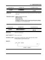
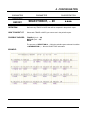
SUB-MATRIX
PARAMETER
CLASSIFICATION
ANALOG INPUT
RANGE
!! !!
DEFINITION:
DISPLAY ACTUATION RANGE
For directly connected temperature sensors and non-linear temperature
transmitters, the actuation selection defines the linearization routine used
to produce a linear chart scale. For linear transmitters, the selection simply
defines the transmitter's range/span.
The choice of actuation offered by the recorder during configuration will
depend upon sensor selected. The ranges allowed will depend on whether
you have selected Thermocouple, Linear or Non Linear or RTD.
HOW TO MODIFY IT:
Select a new actuation using the # or
POSSIBLE VALUES:
Depends on the type of sensor connected. Possible selections are listed
below.
4-9
!arrows and press ENTER
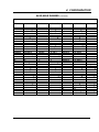
4. CONFIGURATION
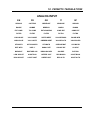
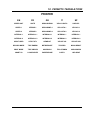
AVAILABLE RANGES
LINEAR
DISPLAY
RANGE
RTD / OHMS
DISPLAY
mV:
mV:
0/10 mV
0, 10 mV
Pt 100 Ω at 0
-50/150 C
-10/10 mV
-10, 0, 10 mV
0/ 20 mV
°C
RANGE
° C:
DISPLAY
RANGE
JIS:
JIS:
-50, 0, 150°C
-50/150 C
-50, 0, 150°C
-58/302 F
-58, 0, 302°F
-58/302 F
-58, 0, 302°F
0, 20 mV
0/100 C
0, 100°C**
0/100 C
0, 100°C**
-20/20 mV
-20, 0, 20 mV
32/212 F
32, 212°F**
32/212 F
32, 212°F**
0/50 mV
0, 50 mV
0/200 C
0, 200°C
0/200 C
0, 200°C
-50/50 mV
-50, 0, 50 mV
32/392 F
32, 392°F
32/392 F
32, 392°F
10/50 mV
10, 50 mV
0/400 C
0, 400°C
0/400 C
0, 400°C
0/100 mV
0, 100 mV
32/752 F
32, 752°F
32/752 F
32, 752°F
-100//100 mV
-100, 0, 100 mV
-200/800 C
-200, 0, 800°C
-200/500 C
-200, 0, 500°C
0/500 mV
0, 500 mV
-328/1472 F
-328, 0, 1472°F
-328/932 F
-328, 0, 932°F
-500/500 mV
-500, 0, 500 mV
Volt:
Ni 50 ohms:
320 C
Ni 50 ohms:
Volt:
0/1 V
0, 1 V
608 F
-112, 0, 608°F
-1/1 V
0/2 V
-2/2 V
-1, 0, 1 V
0, 2 V
-2, 0, 2 V
Ni 508 ohms:
150 C
Ni 508 ohms:
0/5 V
0, 5 V
302 F
-112, 0, 302°F
-5/5 V
1/5 V
0/10 V
-5, 0, 5 V
1, 5 V
0, 10 V
Cu 10 ohms:
250 C
Cu 10 ohms:
-10/10 V
-10, 0, 10 V
482 F
-4, 0, 482°F***
mA:
0/20 mA
4/20 mA
mA:
0, 20 mA*
4, 20 mA*
Ohms:
0/200 Ω
0/2000 Ω
Ohms:
0, 200 Ω
0, 2000 Ω
Pt 100 Ω at 0
-80, 0, 320°C
-80, 0, 150°C
-20, 0, 250°C***
* The mA inputs have to be connected on a 250 Ω input resistor across the input terminals.
** Accuracy: 0.25 %
*** Accuracy: 0.5 %
4-10
4. CONFIGURATION
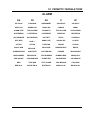
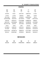
AVAILABLE RANGES (continued)
THERMOCOUPLES
DISPLAY
J:
RANGE
DISPLAY
RANGE
DISPLAY
RANGE
J:
S:
S:
U:
U:
-50/150 C
-50/150 C
-58/302 F
0/400 C
32/752 F
-200/870 C
-328/1598 F
-50, 0, 150°C
-50, 0, 150°C
-58, 0, 302°F
0, 400°C
32, 752°F
-200, 0, 870°C
-328, 0, 1598°F
0/1600 C
0/1600 C
32/2912 F
-20/1760 C
-4/3200 F
0, 1600°C
0, 1600°C
32, 2912°F
-20, 0, 1760°C
-4, 0, 3200°F
L:
-50/150 C
-58/302 F
0/400 C
32/2552 F
-200/870 C
-328/1598 F
L:
-50, 0, 150°C
-58, 0, 302°F
0, 400°C
32, 2552°F
-200, 0, 870°C
-328, 0, 1598°F
N:
0/400 C
32/752 F
0/800 C
32/1472 F
0/1200 C
32/752 F
-200/1300 C
-328/2372 F
N:
0, 400°C
32, 752°F
0, 800°C
32, 1472°F
0/1200°C
32, 752°F
-200, 0,1300°C
-328, 0, 2372°F
50/150 C
-50/150 C
-58/302 F
0/150 C
32/302 F
50/150 C
122/302 F
-200/400 C
-328/752 F
50, 0, 150°C
-50, 0, 150°C
-58, 0, 302°F
0, 150°C
32, 302°F
50, 150°C
122, 302°F
-200, 0, 400°C
-328, 0, 752°F
NiMo:
0/1400 C
32/2192 F
NiMo:
0, 1400°C
32, 2192°F
K:
0/400 C
32/752 F
0/800 C
32/1472 F
0/1200 C
32/2192 F
K:
0, 400°C
32, 752°F 0, 800°C
32, 1472°F
0, 1200°C
32, 2192°F
W-W26:
-20/2320 C
-4/4208 F
W-W26:
-20, 0, 2320°C
-4, 0, 4208 °F
Reference
Range
500, 2100°C
932, 3812 °F
-200, 0, 1370°C
-328, 0, 2498°F
T:
-50, 0, 150°C
-58, 0, 302°F
0, 150°C
32, 302°F
50, 150°C
122, 302°F
-200, 0, 400°C
-328, 0, 752°F
Moco:
0, 1400°C
32, 2552 oF
-200/1370 C
-328/2498 F
T:
-50/150 C
58/302 F
0/150 C
32/302 F
50/150 C
122/302 F
-200/400 C
-328/752 F
Moco:
0, 1400 C
32/2552 F
W5-W26:
-20/2320 C
-4/4208 F
W5-W26:
-20, 0, 2320°C
-4, 0, 4208°F
0, 1800°C
32, 3272°F
PR20-40:
PR20-40:
R:
-20/1760 C
-4/3200 F
R:
-20, 0, 1760°C
-4, 0, 3200°F
PR20 1800C
PR20 3272 F
0, 1800°C
32, 3272°F
600, 1800°C
1110, 3300°F
B:
40/1820 C
104/3308 F
B:
400, 1820 oC
752, 3308oF
400, 1820 °C
752, 3308 °F
4-11
4. CONFIGURATION
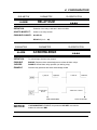
SUB-MATRIX
PARAMETER
CLASSIFICATION
ANALOG INPUT
RANGE
!! !!
NOTE:
For non-linear signals TR NL 0 - 5 V, 1 - 5 V, 0 - 20 mA, 4 - 20 mA, 1 to
5 VDC or 4 to 20 mA or 0 to 5 VDC or 0 to 20 mA, the transmitter range
must be identical to the range shown in the previous tables.
NOTICE
F is used for °Fahrenheit ; C is used for °Celsius.
4-12
4. CONFIGURATION
SUB-MATRIX
PARAMETER
CLASSIFICATION
ANALOG INPUT
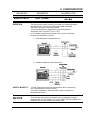
EXT COMP
!! !!
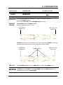
DEFINITION:
The thermocouple sensor is directly connected to a remote temperature
compensation box. Then the connections are made with copper
lead wires. Two types of wiring are possible:
1) At a fixed temperature compensation box with temperature
o
o
configurable from 0 up to 80 C (32 to 176 F).
2) On variable temperature compensation box. We use 1 channel to
measure the temperature of the box.
1) Fixed temperature compensation box
2) Variable temperature compensation box
HOW TO MODIFY IT:
1) Fixed Temperature: Enter a new temperature value in engineering
unit. Choose between VALUE 0 and 80.
2) Variable Temperature: Select the channel used to measure the
temperature of the box.
NOTICE
This parameter is just taken into account if the corresponding channel is
configured with T/C EXT COMP. For T/C INT COMP, RTD and LINEAR, this
parameter has no effect whatever the entered value.
4-13
4. CONFIGURATION
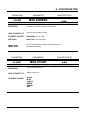
SUB-MATRIX
PARAMETER
CLASSIFICATION
ANALOG INPUT
FILTER
!! !
DEFINITION:
You may wish to apply a filter to noisy signals. However if pulses, square
waves or other rapidly changing inputs are to be displayed and recorded
without damping, choose 0 filter value.
HOW TO MODIFY IT:
POSSIBLE VALUES:
Enter a numeric value.
0-99 seconds
0 = No filter
10 = 10 seconds
NOTICE
All the alarms or maths functions configured on a filtered analog input are
affected by the filter delay. Be mindful with the filter action for the channels on
which a "rate of change" alarm is configured: the filter can suppress the alarm
action.
4-14
4. CONFIGURATION
SUB-MATRIX
PARAMETER
CLASSIFICATION
ANALOG INPUT
LOW VALUE
!! !
DEFINITION:
Engineering value corresponding to low limit of the selected input
actuation range.
HOW TO MODIFY IT:
Enter a numeric value.
POSSIBLE VALUES:
Up to 4 digits plus optional sign.
[-9999 ... 9999]
NOTICE
Modification is not allowed for any directly connected temperature sensors, as
this would adversely affect the linearization.
Modification is only possible when the sensor is:
- LINEAR or SPECIAL
- RTD and the range is 0, 200 Ohms or 0, 2000 Ohms
NOTICE
For linear and non-linear transmitters choose the value in engineering
units, which corresponds to the low range limit of the transmitter.
SUB-MATRIX
PARAMETER
CLASSIFICATION
ANALOG INPUT
HIGH VALUE
!! !
DEFINITION:
Engineering value corresponding to high limit of the selected input actuation
range.
HOW TO MODIFY IT:
Enter a numeric value.
POSSIBLE VALUES:
Up to 4 digits plus optional sign.
[-9999 ... 9999]
NOTICE
Modification is not allowed for any directly connected temperature sensors, as
this would adversely affect the linearization.
Modification is only possible when the sensor is:
- LINEAR or SPECIAL
- RTD and the range is 0, 200 Ohms or 0, 2000 Ohms
NOTICE
For linear and non-linear transmitters choose the value in engineering
units, which corresponds to the low range limit of the transmitter.
4-15
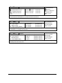
4. CONFIGURATION
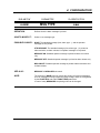
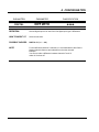
SUB-MATRIX
PARAMETER
CLASSIFICATION
ANALOG INPUT
STD MATH
!! !!
DEFINITION:
2 mathematical functions are included as standard in the recorder.
These functions apply only to analog inputs.
HOW TO MODIFY IT:
Select the maths function.
POSSIBLE CHOICES:
NO OPT MATH: No maths function configured.
SQUARE ROOT: Square root applies to analog input.
CHANNEL DIFF: Difference between the current analog input and the one
configured in "DIFF WITH".
SEE ALSO:
DIFF WITH in this sub-matrix for CHANNEL DIFF.
NOTE:
1) For SQUARE ROOT the formula is:
Smin = min. sensor input value
Smax = max. sensor input value
S = current sensor input value
Available for linear inputs
2) For CHANNEL DIFF, the formula is:
PV = PVA - PVB
A and B are any analog input.
4-16
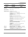
4. CONFIGURATION
SUB-MATRIX
PARAMETER
CLASSIFICATION
ANALOG INPUT
DIFF WITH
!! !!
DEFINITION:
Second channel used when STD MATH = CHANNEL DIFF
HOW TO MODIFY IT:
Select a new value.
POSSIBLE CHOICES:
ANALOG # i (i = 1 ... 64)
NONE
NOTE:
The software will only allow selection of pre-configured input.
For the difference between 2 channels, it is recommended to take
first the highest channel reference and subtract from the other channel.
Example:
You want to make a difference between channels 7 and 12:
make ch12 minus ch7.
4-17
4. CONFIGURATION
SUB-MATRIX
PARAMETER
CLASSIFICATION
ANALOG INPUT
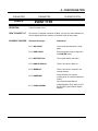
BURNOUT
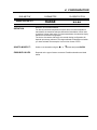
!! !!
DEFINITION:
Allows you to define the safety backup position to activate alarms (if
configured) in case of sensor burnout. The trace can go either on the right
(high) or on the left (low).
HOW TO MODIFY IT:
Select new text.
POSSIBLE CHOICES:
NO BURNOUT: No burnout.
B OUT LOW: Burnout configured low scale. Display shows [-9999]
B OUT HIGH: Burnout configured high scale. Display shows [9999]
FIX LOW: Value fixed low. (mA) Not configurable
FIX HIGH: Value fixed high. (RTD/OHMS) Not configurable
FIX NONE: Undefined value. Not configurable (Linear sensors)
0 to 10 V / - 5 to 5 V / -1 to 1 V / -500 to 500 mV
- For some sensors (mA, RTD, Volts), burnout is not configurable but fixed
and display will show FIX LOW, FIX HIGH or FIX NONE.
The value will be out of range (low, high or undefined). The "BURNOUT" event
is only activated with the B OUT LOW or B OUT HIGH configuration.
- For RTD/OHMS sensors, a third wire burnout cannot be detected: the output
value will be undefined.
NOTE:
! CAUTION
For configurable burnout, be aware that a current pulse of 0.125 mA will
occur regularly as part of the burnout detection and may disturb other
devices connected to the same sensor. For an application with another
controller connected on the same current loop, please remove the
burnout detection on your recorder.
Failure to comply with these instructions may result in product damage
4-18
4. CONFIGURATION
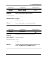
SUB-MATRIX
PARAMETER
CLASSIFICATION
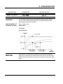
ANALOG INPUT
LOW ADJUST
HIGH ADJUST
!! !
DEFINITION:
Zero adjust and span adjust are values used to calibrate a temperature loop.
Otherwise choose 0 Value = Factory Calibration
Adjustments are made directly in Engineering unit to the input range.
o
(ex.: 5 = 5 C)
HOW TO MODIFY IT:
Enter a numeric value.
POSSIBLE CHOICES:
Up to 3 digits including negative sign and decimal point.
[-99 ... +99]
EXAMPLE:
LOW ADJUST will be added to the 0% of the considered range.
HIGH ADJUST will be added to the 100% of the considered range, so the
calibration is changed.
4-19
4. CONFIGURATION
4-20
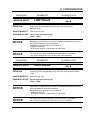
4. CONFIGURATION
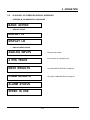
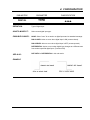
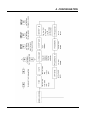
SUB – MATRIX
PARAMETERS
CHART
Configuration of chart range and format
TRACE
page 4-21
DESTINATION
page 4-21
FORMAT
page 4-22
MIN RANGE 1
page 4-22
MAX RANGE 1
page 4-23
RG 1 COLOR
page 4-23
MIN RANGE 2
page 4-24
MAX RANGE 2
page 4-24
RG 2 COLOR
page 4-25
ENG UNIT
page 4-25
TAG NAME
page 4-26
RANGE USED
page 4-26
0% ZONE
page 4-27
100% ZONE
page 4-27
SUB DIV
page 4-28
GROUP DEF
page 4-29
4-21
4. CONFIGURATION
SUB-MATRIX
PARAMETER
CLASSIFICATION
CHART
TRACE
!! !!
DEFINITION:
Defines the variable to be printed on the chart or stored on the PCMCIA
memory card (None, Analog input 1... 24, Comm input 1 ... 24, maths input
1 ... 24).
HOW TO MODIFY IT:
Select a new value.
POSSIBLE CHOICES:
NO TRACE
ANALOG # i (i = 1 ... 64)
COMM # i (i = 1 ... 32)
MATH # i (i = 1 ... 32)
NOTICE
The software will only allow selection of a pre-configured analog input.
SUB-MATRIX
PARAMETER
CLASSIFICATION
CHART
DESTINATION
!! !!
DEFINITION:
Determines where to print or copy charts.
HOW TO MODIFY IT:
Select a new value.
POSSIBLE CHOICES: ON PAPER
ON FILE *
PAPER & FILE *
* FILE: this corresponds to the trace storage on a PCMCIA memory card.
DEFAULT VALUE:
ON PAPER
4-22
4. CONFIGURATION
SUB-MATRIX
PARAMETER
CLASSIFICATION
CHART
FORMAT
! !!
DEFINITION:
Format used for the printing of trend, range and information, and the display of
trace value.
POSSIBLE CHOICES:
XXXXX (no decimal point) 10000
XXX.X (1/10) 100.0
XX.XX (1/100) 10.00
X.XXX (1/1000) 1.000
AUTOMATIC: Automatically displays and prints the measured value based on
the accuracy of the recorder and the available number of digits on the display.
IE ACCURACY = 0.1% on selected ranges.
SUB-MATRIX
PARAMETER
CLASSIFICATION
CHART
MIN RANGE 1
!! !
DEFINITION:
Lower limit of chart range 1.
HOW TO MODIFY IT: Enter a numeric value.
POSSIBLE VALUES: Up to 8 digits for analog inputs, maths results and comm. results.
Including negative sign and decimal point.
EXAMPLE:
4-23
4. CONFIGURATION
SUB-MATRIX
PARAMETER
CLASSIFICATION
CHART
MAX RANGE 1
!! !
DEFINITION:
Upper limit of chart range 1
HOW TO MODIFY IT: Enter a numeric value.
POSSIBLE VALUES: Up to 8 digits for analog inputs, maths results and comm. results.
Including negative sign and decimal point.
EXAMPLE:
SUB-MATRIX
PARAMETER
CLASSIFICATION
CHART
RG1 COLOR
!!
DEFINITION:
Color of range 1.
HOW TO MODIFY IT:
Select a new color
POSSIBLE VALUES:
BLACK
BLUE
PURPLE
GREEN
BROWN
RED
BLACK THICK
BLUE THICK
PURPLE THICK
GREEN THICK
BROWN THICK
RED THICK
4-24
4. CONFIGURATION
SUB-MATRIX
PARAMETER
CLASSIFICATION
CHART
MIN RANGE 2
!! !
DEFINITION:
Lower limit of chart range 2.
HOW TO MODIFY IT: Enter a numeric value.
POSSIBLE VALUES: Up to 8 digits for analog inputs, maths results and comm. results.
Including negative sign and decimal point.
EXAMPLE:
SUB-MATRIX
PARAMETER
CLASSIFICATION
CHART
MAX RANGE 2
!! !
DEFINITION:
Upper limit of chart range 2
HOW TO MODIFY IT: Enter a numeric value.
POSSIBLE VALUES: Up to 8 digits for analog inputs, maths results and comm. results.
Including negative sign and decimal point.
EXAMPLE:
4-25
4. CONFIGURATION
SUB-MATRIX
PARAMETER
CLASSIFICATION
CHART
RG2 COLOR
! !
DEFINITION:
Color of range 2.
HOW TO MODIFY IT:
Select a new color
POSSIBLE VALUES:
BLACK
BLUE
PURPLE
GREEN
BROWN
RED
BLACK THICK
BLUE THICK
PURPLE THICK
GREEN THICK
BROWN THICK
RED THICK
SUB-MATRIX
PARAMETER
CLASSIFICATION
CHART
ENG UNIT
! !
DEFINITION:
Chart channel units.
HOW TO MODIFY IT:
Enter a text.
POSSIBLE CHOICES: 5 alpha numerical characters max.
EXAMPLES:
- mm/h
- Deg F
- Deg C
- PSI
- BAR
- µA
NOTICE
When PCMCIA option is configured any modifications of ENG UNIT parameter
will be forbidden while storage is running.
Refer to the PCMCIA Option Manual for more details.
4-26
4. CONFIGURATION
SUB-MATRIX
PARAMETER
CLASSIFICATION
CHART
TAG NAME
! !
DEFINITION:
Name of the chart channel.
HOW TO MODIFY IT:
Enter a text.
POSSIBLE CHOICES:
8 alpha numerical characters.
EXAMPLES:
NOTICE
-
REACTOR
-
FURNACE
-
AUTOCLAV
When PCMCIA option is configured any modifications of TAG NAME
parameter will be forbidden while storage is running.
Refer to the PCMCIA Option Manual for more details.
SUB-MATRIX
PARAMETER
CLASSIFICATION
CHART
RANGE USED
!!!!
DEFINITION:
You may select whether the input channel will be printed normally
(range 1 or 2) or on alarm (with range 1 or 2).
HOW TO MODIFY IT:
Select a new value.
POSSIBLE CHOICES:
NOTE:
}
}
WITH RG1
WITH RG2
RG1 ON ALARM
RG2 ON ALARM
SEE ALSO:
Select the range used in normal printing.
Only if you have selected " PRINT ON
AL" in sub-matrix ALARM you have
to select the RG1 ON ALARM or
RG2 ON ALARM
Parameter ACTION in ALARM sub-matrix.
Parameter ACTION in DIGITAL sub-matrix.
Parameter GROUP DEF in CHART sub-matrix.
4-27
4. CONFIGURATION
SUB-MATRIX
PARAMETER
CLASSIFICATION
CHART
0% ZONE
100% ZONE
!!!
DEFINITION:
Defines chart zone for printing.
HOW TO MODIFY IT:
Enter a new value.
POSSIBLE CHOICES:
0...100% - - - - > 0...80% for 0% zone of paper - - - - > 20...100% for 100%
zone
The choice of parameters for 0% and 100% zone allows you to define the
datum such that the width of the chart paper is less than the calibrated
width of the paper.
This function permits the segregation of input traces into zones to avoid
the problem of input signals using the same paper scale and having the
same values printed on top of each other.
The minimum width per zone is 20% of the chart.
NOTE:
The zoning is only possible in TREND mode.
SEE ALSO:
PRINTER matrix and PRINT MODE parameter.
SUB DIV = NO DIVISION when zoning is < 100%
SUB-MATRIX
PARAMETER
CLASSIFICATION
CHART
0% ZONE
100% ZONE
!!!
EXAMPLE:
0%
ZONE 1
100% ZONE 1
0% ZONE 2
4-28
100%
ZONE 2
4. CONFIGURATION
SUB-MATRIX
PARAMETER
CLASSIFICATION
CHART
SUB DIV
!!
DEFINITION:
This parameter allows the visualization of a scale on the paper in addition to
the classic RANGE message.
Refer to the CHART DOC matrix, INFORMATION # parameter.
POSSIBLE
CHOICES:
NO DIVISION: Standard RANGE message.
Example: Chart scale printed in 1 line.
POSITION 0%
CHART DOC
POSITION 100%
CHART DOC
DIVISION: Subdivisions (Configurable from 0 to 9) to be printed in RANGE scale printing.
Example: Chart scale printed in 2 lines. 3 subdivisions, 2 lines printing.
POSITION 0%
CHART DOC
3 SUBDIVISIONS
POSITION 100%
CHART DOC
SEE ALSO:
See INFORMATION parameter in CHART DOC sub-matrix, with RANGE choice.
NOTICE
In ZONING mode (0% ZONE ! 0 and 100% ZONE ! 100), the SUB DIV parameter is
considered as equivalent to NO DIVISION.
4-29
4. CONFIGURATION
SUB-MATRIX
PARAMETER
CLASSIFICATION
CHART
GROUP DEF
!!!!
DEFINITION:
This defines two separate groups of channels that will be printed together as a
group
POSSIBLE CHOICES:
NO GROUP: Trace not affected by CHG GROUP action.
Prints all configured channels
GROUP A: Trace affected by CHG GROUP action.
Channels only in GROUP A
GROUP B: Trace affected by CHG GROUP action.
Channels only in GROUP B
SEE ALSO:
See ALARM and DIGITAL INPUTS sub-matrices, ACTION parameter,
PRINT GROUP choice.
.
4-30
4. CONFIGURATION
4-31
4. CONFIGURATION
SUB – MATRIX
ALARM
Configuration of alarm set point with its action
PARAMETERS
SP VALUE
page 4-32
APPLY ON
page 4-32
ALARM TYPE
page 4-33
HYSTERESIS
page 4-35
OCCURRENCE
page 4-36
DIFF WITH
page 4-38
ACTION
page 4-39
RELAY NUM
page 4-40
ACKNOWLEDGE
page 4-40
MSG NUMBER
page 4-41
MSG COLOR
page 4-41
MSG TYPE
page 4-42
RED IN AL
page 4-45
4-32
4. CONFIGURATION
SUB-MATRIX
PARAMETER
CLASSIFICATION
ALARM
SP VALUE
!!
DEFINITION:
The alarm switches from OFF to ON when the SP value is reached.
HOW TO MODIFY IT:
Enter a numeric value.
POSSIBLE VALUES:
Up to 7 digits plus optional sign and decimal point in various
engineering units, depending on the channel type.
[-9999999 ... 9999999]
3 digits after the decimal point available
SEE ALSO:
ALARM TYPE in the same sub-matrix.
EXAMPLE:
High alarm type:
SUB-MATRIX
PARAMETER
CLASSIFICATION
ALARM
APPLY ON
!!!!
DEFINITION:
Channel on which the alarm is applied (Analog 1 ... 64, Comm 1 ... 32,
maths 1 ... 32).
POSSIBLE CHOICES:
Select a new value.
SEE ALSO:
ANALOG # i (i = 1 ... 64)
COMM # i (i = 1 ... 32)
MATH # i (i = 1 ... 32)
4-33
4. CONFIGURATION
SUB-MATRIX
PARAMETER
CLASSIFICATION
ALARM
ALARM TYPE
!!!!
DEFINITION:
Type of alarm
HOW TO
MODIFY IT:
POSSIBLE
VALUES:
Select a new alarm type.
NONE: Select "none" for unused alarms.
ALARM HIGH: Alarm to occur when the value equals or exceeds the
alarm setpoint.
ALARM LOW: Alarm to occur when the value equals or is below the
alarm setpoint.
CHG RATE H: Alarm to occur if the trace increases quicker than the
alarm setting. The SP value used is the absolute value of the input value.
(setpoint is given in engineering unit/second)
CHG RATE L: Alarm to occur if the trace decreases quicker than the
alarm setting. The SP value used is the absolute value of the input value.
(setpoint is given in engineering unit/second)
CHG RATE H, L: Alarm to occur if the trace increases/decreases
quicker than the alarm setting. The SP value used is the absolute value of
the input value. (setpoint is given in engineering unit/second)
DIFFERENTIAL: Occurs if the absolute difference between the values of
the specified channel and a second channel exceeds the absolute value of
the alarm setpoint.
SEE ALSO:
DIFF WITH for DIFFERENTIAL in this sub-matrix.
4-34
4. CONFIGURATION
4-35
4. CONFIGURATION
SUB-MATRIX
PARAMETER
CLASSIFICATION
ALARM
HYSTERESIS
!!
DEFINITION: Establishes the alarm hysteresis. Alarms switch ON at set point but switch OFF value
depends on the hysteresis setting.
Hysteresis is expressed in Engineering units and is added to low alarm and subtracted from
high alarm set points to establish the alarm release value.
HOW TO
MODIFY:
POSSIBLE
VALUES
Enter a numeric value of up to 3 digits, with optional decimal point.
[0.0 ... 999] (including decimal point)
3 digits after the decimal point available
EXAMPLE:
NOTE:
With CHG rate type, this parameter is expressed in Engineering units.
4-36
4. CONFIGURATION
SUB-MATRIX
PARAMETER
CLASSIFICATION
ALARM
OCCURRENCE
!!!!
DEFINITION:
Defines the number of alarm occurrences that must occur after power on
before alarm activation can actually operate. This acts as a filter for the
alarm activation.
HOW TO MODIFY IT:
Select a new value.
POSSIBLE VALUES:
[0 ... 9]
0 = No alarm occurrence (ie: normal alarm activation)
1 = 1 alarm occurrence
2 = 2 alarm occurrences
.
.
.
9 = 9 alarm occurrences
EXAMPLE:
High alarm type configured with alarm occurrence = 1
At start up (power on) PV < SP, the alarm is inactive.
The first alarm (occurrence #1) is disregarded, the second alarm causes the
alarm to be activated.
4-37
4. CONFIGURATION
SUB-MATRIX
PARAMETER
CLASSIFICATION
ALARM
OCCURRENCE
!!!!
Occurrence value is reset to the configured value after:
- Power on
- Entering in configuration mode (selection of any parameter marked with
- An immediate action RESET OCCURRENCE
4-38
!!, see page 4-2).
4. CONFIGURATION
SUB-MATRIX
PARAMETER
CLASSIFICATION
ALARM
DIFF WITH
!!!!
DEFINITION:
Second channel used if alarm type is differential.
HOW TO MODIFY IT:
Select a new value.
POSSIBLE VALUES:
The same as those for alarm channel.
ANALOG # i (i = 1 ... 64)
COMM # i (i = 1 ... 32)
MATH # i (i = 1 ... 32)
NOTE:
For the difference between 2 channels, it is recommended to take first the
highest channel reference and subtract from the other channel.
Example:
You want to make a difference between channels 7 and 12: make ch12 minus
ch7.
4-39
4. CONFIGURATION
SUB-MATRIX
PARAMETER
CLASSIFICATION
ALARM
ACTION
!!!!
DEFINITION:
Action on printer in case of alarm.
HOW TO MODIFY IT:
Select a new alarm action.
POSSIBLE VALUES:
NO ACTION: No effect on printing.
CHG SPD/INT: Change chart speed/print interval.
CHG RANGE: Change to range 2 if RANGE USED = with R1 and to range 1 if
RANGE USED = with R2
PRINT ON AL: Prints the channel trace when alarm condition occurs.
PRT INHIBIT: Stop all printing without data acquisition.
TAB SQTRACE: Print one tabular snapshot of values superimposed on
traces.
TAB SQBLANK: Print one tabular snapshot of values on blank paper.
PRT MATH LOG: Print one tabular snapshot of maths results.
CHG GROUP B:
CHG GROUP A to B: Print groups # i of channels defined in CHART submatrix.
When the alarm turns ON, the group B is printed.
When the alarm turns OFF, the group A is printed.
CHG GROUP AB:
CHG GROUP A to A + B: Print groups # i of channels defined in CHART submatrix.
When the alarm turns ON, groups A and B are printed.
When the alarm turns OFF, the group A is printed.
SEE ALSO:
RANGE USED in CHART sub-matrix for PRINT ON AL and CHG GROUP
GROUP DEF in CHART sub-matrix for CHG GROUP
4-40
4. CONFIGURATION
SUB-MATRIX
PARAMETER
CLASSIFICATION
ALARM
RELAY NUM
!!!!
DEFINITION:
Selection of the relay to activate in alarm condition.
HOW TO MODIFY IT:
Select a new relay number.
POSSIBLE CHOICES:
NO RELAY
RELAY # i (i = 1 ... 48)
SUB-MATRIX
PARAMETER
CLASSIFICATION
ALARM
ACKNOWLEDGE
!!!!
DEFINITION:
To acknowledge all alarm relay outputs.
POSSIBLE
CHOICES:
ENABLE: Requires alarm acknowledgment to release all alarm relays
DISABLE: Normal alarm relay operation (no latching relay)
EXAMPLE:
Of alarm relay operation with Alarm acknowledge enable
NOTICE
If ACKNOWLEDGE is ENABLE, the parameter ACK KEY must also be
enabled in sub-matrix MMI.
4-41
4. CONFIGURATION
SUB-MATRIX
PARAMETER
CLASSIFICATION
ALARM
MSG NUMBER
!!!
DEFINITION:
Selection of the alarm message to be printed.
HOW TO MODIFY IT:
Select a new message number.
POSSIBLE VALUES:
MESSAGE # i (i = 1 ... 64)
SEE ALSO:
MSG TYPE in this sub-matrix
NOTICE
Be sure the selected message is already configured.
(See Matrix Message)
SUB-MATRIX
PARAMETER
CLASSIFICATION
ALARM
MSG COLOR
!!!
DEFINITION:
Color of alarm message.
HOW TO MODIFY IT:
Select a new color.
POSSIBLE VALUES:
BLACK
BLUE
PURPLE
GREEN
BROWN
RED
4-42
4. CONFIGURATION
SUB-MATRIX
PARAMETER
CLASSIFICATION
ALARM
MSG TYPE
!!!
DEFINITION:
Defines when the alarm message is printed.
HOW TO MODIFY IT:
Select a new message type.
POSSIBLE CHOICES:
NONE: The standard message (time, alarm type ...), and the operator
message are not printed.
STD MESSAGE: The standard message (time, alarm type...) is printed at
alarm activation, at alarm release, but operator message is not printed.
MESSAGE ON: Standard operator message is printed at alarm occurrence
only.
MESSAGE OFF: Standard operator message is printed at alarm release only.
MSG ON/OFF: Standard operator message is printed at alarm activation and
at alarm release.
SEE ALSO:
MESSAGE in MESSAGES sub-matrix
NOTE:
The selection of NONE does not prevent the printing of functional messages
such as, messages of range, speed and group change, these are configurable
by the CHART DOC sub-matrix FUNCT MSG parameters.
In case of many MESSAGES the printing order can be changed.
4-43
4. CONFIGURATION
NONE
STD MESSAGE
MESSAGE ON
4-44
4. CONFIGURATION
MESSAGE OFF
MESSAGE ON/OFF
4-45
4. CONFIGURATION
SUB-MATRIX
PARAMETER
CLASSIFICATION
ALARM
RED IN AL
!!!!
DEFINITION:
Specifies if the trend trace will be printed in red during alarm condition.
HOW TO MODIFY IT:
Choose a new selection.
POSSIBLE CHOICES:
NO
YES
SEE ALSO:
If RED IN AL is selected, do not configure the trace color in red as
normal printing.
4-46
4. CONFIGURATION
4-47
4. CONFIGURATION
SUB – MATRIX
DIGITAL
Configuration of digital input parameters with their actions
PARAMETERS
TYPE
page 4-48
DIFF WITH
page 4-49
ACTION
page 4-50
RELAY NUM
page 4-51
ACKNOWLEDGE
page 4-51
MSG NUM
page 4-52
MSG COLOR
page 4-52
MSG TYPE
page 4-53
TRACE
page 4-53
OFF POSITN
page 4-54
ON POSITN
page 4-54
TRACE COLOR
page 4-55
RED IN AL
page 4-55
4-48
4. CONFIGURATION
SUB-MATRIX
PARAMETER
CLASSIFICATION
DIGITAL
TYPE
!!!!
DEFINITION:
Type of digital input.
HOW TO MODIFY IT:
Select a new digital input type.
POSSIBLE CHOICES:
NONE: Select "none" for no action on digital inputs and no standard message.
DIG CLOSED: Action to occur when digital input is ON (contact closed).
DIG OPENED: Action to occur when digital input is OFF (contact opened).
DIFFERENTIAL: Action to occur when digital input changes to a different state
from another specified digital input. (Function XOR)
SEE ALSO:
DIFF WITH for DIFFERENTIAL in this sub-matrix.
EXAMPLE:
4-49
4. CONFIGURATION
SUB-MATRIX
PARAMETER
CLASSIFICATION
DIGITAL
DIFF WITH
!!!!
DEFINITION:
Second digital input to be used if the first digital input type is differential.
HOW TO MODIFY IT:
Select a new value.
POSSIBLE CHOICES:
DIGITAL # i (i = 1 ... 48)
NOTE:
For the difference between 2 channels, it is recommended to take first the
highest channel reference and subtract from the other channel.
Example:
You want to make a difference between channels 7 and 12:
make ch12 minus ch7.
4-50
4. CONFIGURATION
SUB-MATRIX
PARAMETER
CLASSIFICATION
DIGITAL
ACTION
!!!!
DEFINITION:
Action on printer in case of digital input change.
HOW TO MODIFY IT:
Select a new action.
POSSIBLE CHOICES:
NO ACTION: No effect on printing.
CHG SPD/INT: Change chart speed/print interval.
CHG RANGE: Change to range 2 if RANGE USED = with R1 and to range 1
if RANGE USED = with R2
PRINT ON AL: Print the channel in alarm condition.
PRT INHIBIT: Stop all printing without data memorization.
TAB SQTRACE: Print one tabular snapshot of values superposed on traces.
TAB SQBLANK: Print one tabular snapshot of values on blank paper.
PRT MATH LOG: Print one tabular snapshot of maths results.
CHG GROUP B:
CHG GROUP A to B: Print groups # i of channels defined in chart sub-matrix
When the alarm turns ON, the group B is printed.
When the alarm turns OFF, the group A is printed.
CHG GROUP AB:
CHG GROUP A to A + B: Print groups # i of channels defined in chart
sub-matrix.
When the alarm turns ON, groups A and B are printed.
When the alarm turns OFF, the group A is printed.
SEE ALSO:
RANGE USED in CHART sub-matrix for PRINT ON AL and CHG GROUP
GROUP DEF in CHART sub-matrix for CHG GROUP
WARNING:
This ACTION parameter is taken into account only if NORMAL is selected for
the SELECTION parameter of the DIGITAL sub-matrix.
4-51
4. CONFIGURATION
SUB-MATRIX
PARAMETER
CLASSIFICATION
DIGITAL
RELAY NUM
!!!!
DEFINITION:
Selection of the relay activated with digital input.
HOW TO MODIFY IT:
Select a new relay number
POSSIBLE CHOICES:
NO RELAY
RELAY # i (i = 1 ... 48)
SUB-MATRIX
PARAMETER
CLASSIFICATION
DIGITAL
ACKNOWLEDGE
!!!!
DEFINITION:
To acknowledge all alarm latching relay outputs.
POSSIBLE CHOICES:
ENABLE: Requires alarm acknowledgment to release all alarm relays.
DISABLE: Normal alarm relay operation (no latching relay).
EXAMPLE:
NOTICE
If ACKNOWLEDGE is ENABLE, the parameter ACK KEY must also be
enabled in sub-matrix MMI.
4-52
4. CONFIGURATION
SUB-MATRIX
PARAMETER
MSG NUM
DIGITAL
CLASSIFICATION
!!!
DEFINITION:
Selection of the message to be printed.
HOW TO MODIFY IT:
Select a new message number.
POSSIBLE CHOICES:
MESSAGE # i (i = 1 ... 64)
SEE ALSO:
MSG TYPE in this sub-matrix
Without message # only the standard message is printed.
SUB-MATRIX
PARAMETER
MSG COLOR
DIGITAL
DEFINITION:
Color of the message.
HOW TO MODIFY IT:
Select a new color.
POSSIBLE CHOICES:
BLACK
BLUE
PURPLE
GREEN
BROWN
RED
4-53
CLASSIFICATION
!!!
4. CONFIGURATION
SUB-MATRIX
PARAMETER
CLASSIFICATION
DIGITAL
MSG TYPE
!!!
DEFINITION:
Defines when the digital message is printed.
HOW TO MODIFY IT:
Select a new MSG TYPE.
POSSIBLE CHOICES:
NONE: The standard message (date, time, alarm type ...), and the operator
message are not printed.
STD MESSAGE: The standard message (date, time, alarm type...) is printed
at alarm activation, at alarm release, but operator message is not printed.
MESSAGE ON: Standard operator message is printed when the digital
contact is closed.
MESSAGE OFF: Standard operator message is printed when the digital
contact is opened.
MSG ON/OFF: Standard operator message is printed when the digital contact
is closed and opened.
SEE ALSO:
MESSAGE in MESSAGES sub-matrix
WARNING:
The selection of NONE does not prevent the printing of functional messages
such as, messages of range, speed and group change, these are configurable
by the CHART DOC sub-matrix FUNCT MSG parameters.
In case of many MESSAGES the printing order can be changed.
SUB-MATRIX
DIGITAL
PARAMETER
TRACE
CLASSIFICATION
!!!!
DEFINITION:
Enable/disable the digital trace.
POSSIBLE CHOICES:
ENABLE
DISABLE
4-54
4. CONFIGURATION
SUB-MATRIX
DIGITAL
PARAMETER
CLASSIFICATION
OFF POSITN
!!!!
DEFINITION:
Defines the trace position (DI = OFF) on the chart. (in %)
One increment = 1%.
EXAMPLE:
See example on next page.
SUB-MATRIX
DIGITAL
PARAMETER
CLASSIFICATION
ON POSITN
!!!!
DEFINITION: Defines the trace position (DI = OFF) on the chart. (in %)
One increment = 1%.
EXAMPLE:
ON POSITION
OFF POSITION
Chart paper
0%
100%
4-55
4. CONFIGURATION
SUB-MATRIX
PARAMETER
TRACE COLOR
DIGITAL
DEFINITION:
Defines the color of the digital trace.
HOW TO MODIFY IT:
Select a new color.
POSSIBLE CHOICES:
BLACK
BLUE
PURPLE
GREEN
BROWN
RED
SUB-MATRIX
PARAMETER
RED IN AL
DIGITAL
CLASSIFICATION
!!!
CLASSIFICATION
!!!!
DEFINITION:
Specifies if the digital input trace will be printed in red with digital action.
HOW TO MODIFY IT:
Select a new value.
POSSIBLE CHOICES:
NO
YES
NOTICE
If RED IN AL is selected: do not configure the trace in red as normal printing.
4-56
4. CONFIGURATION
4-57
4. CONFIGURATION
SUB – MATRIX
MESSAGES
Configuration of customer messages
PARAMETER
MESSAGE
4-58
page 4-58
4. CONFIGURATION
SUB-MATRIX
MESSAGES
PARAMETER
CLASSIFICATION
MESSAGE
!!
DEFINITION:
To configure the messages (1 to 64).
HOW TO MODIFY IT:
Enter text digit by digit with the # and
POSSIBLE CHOICES:
64 alpha numerical characters
NOTICE
If the message is larger than 64 characters, the last digit takes the place of the
first one, giving a wrong message
NOTE:
Configuration of message 1 when used with the tabular printout will create a
header message (This is for software version AM or later). The frequency of
the message being printed is determined via the chart documentation print
interval.
4-59
!
keys
4. CONFIGURATION
4-60
4. CONFIGURATION
SUB – MATRIX
PRINTER
Configuration of the printer operation.
PARAMETERS
SPEED UNIT
page 4-61
SPEED 1
page 4-62
SPEED 2
page 4-63
INTERVAL 1
page 4-64
INTERVAL 2
page 4-64
SP/INT USED
page 4-65
RECORD MODE
page 4-65
PRINT MODE
page 4-66
CHART LG
page 4-67
4-61
4. CONFIGURATION
SUB-MATRIX
PRINTER
PARAMETER
SPEED UNIT
CLASSIFICATION
!!!
DEFINITION:
Speed unit
HOW TO MODIFY IT:
Select a new value.
POSSIBLE CHOICES:
UNIT = mm/h
or
UNIT = inch/h
NOTE:
When the unit is switched from mm/h to inch/h or reverse the chart speed 1
and 2 are converted to the nearest value.
.
4-62
4. CONFIGURATION
SUB-MATRIX
PRINTER
PARAMETER
CLASSIFICATION
SPEED 1
DEFINITION:
Value of speed 1 when PRINT MODE is TREND.
HOW TO MODIFY IT:
Enter a numeric value based on speed unit selected.
POSSIBLE CHOICES:
With mm/h unit:
[1 ... 5000]
or
With inch/h unit:
[0.04 ... 196.86]
!!
Refer to SPEED UNIT to know the speed unit in use.
NOTICE
The following elements may affect the printing performances:
- A fast chart speed.
- A large span printing
- Color arrangements printing
(See chart below for typical worst case)
* The return to the configured speed can be done by executing a PRT INHIBIT or by switching the recorder
off and on or by changing the configuration mode, see page 4-2.
4-63
4. CONFIGURATION
SUB-MATRIX
PRINTER
PARAMETER
CLASSIFICATION
SPEED 2
DEFINITION:
Value of speed 2.
HOW TO MODIFY IT:
Enter a numeric value based on speed unit selected.
POSSIBLE CHOICES:
With mm/h unit:
[1 ... 5000]
or
With inch/h unit:
[0.04 ... 196.86]
!!
Refer to SPEED UNIT to know the speed unit in use.
NOTICE
The following elements may affect the printing performances:
- A fast chart speed.
- A large span printing
- Color arrangements printing
(See chart below for typical worst case)
The return to the configured speed can be done by executing a PRT INHIBIT or by switching the
recorder off and on or by changing the configuration mode, see page 4-2.
4-64
4. CONFIGURATION
SUB-MATRIX
PRINTER
PARAMETER
INTERVAL 1
DEFINITION:
Tab 1 prints interval. (In minutes)
HOW TO MODIFY IT:
Select a new time.
POSSIBLE CHOICES:
to 1440 minutes
SEE ALSO:
PRINT MODE in this sub-matrix.
SUB-MATRIX
PRINTER
PARAMETER
INTERVAL 2
DEFINITION:
Tab 2 prints interval. (In minutes)
HOW TO MODIFY IT:
Select a new time.
POSSIBLE CHOICES:
to 1440 minutes
SEE ALSO:
PRINT MODE in this sub-matrix.
4-65
CLASSIFICATION
!!
CLASSIFICATION
!!
4. CONFIGURATION
SUB-MATRIX
PARAMETER
CLASSIFICATION
PRINTER
SP / INT USED
!!
DEFINITION:
Defines speed in use in alarm off.
HOW TO MODIFY IT:
Select a new speed.
POSSIBLE CHOICES:
SPEED 1
SPEED 2
NOTE:
If printing mode (PRINT MODE) is TABULAR, SPEED 1, SPEED 2 is
understood to be INTERVAL 1, INTERVAL 2.
SUB-MATRIX
PARAMETER
RECORD MODE
PRINTER
CLASSIFICATION
!!!!
DEFINITION:
Recording mode allows you to print normally or to stop the printer.
HOW TO MODIFY IT:
Select a new value.
POSSIBLE CHOICES:
INHIBIT
PRINT
NOTICE
The selection of INHIBIT takes priority over PRINT INHIBIT requested on
ALARM or with BASIC ACTIONS.
4-66
4. CONFIGURATION
SUB-MATRIX
PRINTER
PARAMETER
PRINT MODE
CLASSIFICATION
!!!!
DEFINITION:
Under this heading you must choose whether recording will be in TREND
mode or TABULAR mode.
HOW TO MODIFY IT:
Select a new printing mode.
POSSIBLE CHOICES:
TREND: All channels recorded as trends.
TABULAR: All channels recorded in tabular format.
TREND WITH HEADING: All channels recorded as trends and in tabular form.
NOTE:
In tabular mode, you define the time interval between 2 print-outs (chart speed
being defined in trend mode).
In trend with heading mode, the header needs to be specified in message
number one. The frequency that header info appears on the tabualr chart can
be adjusted by chart-doc print interval.
EXAMPLE:
TREND
TABULAR
TABULAR WITH HEADING
4-67
4. CONFIGURATION
SUB-MATRIX
PRINTER
PARAMETER
CLASSIFICATION
CHART LG
!!
DEFINITION:
Specifies the chart length of the chart roll or fanfold which actuates the event
alarm.
This is used with the recorder EVENTS to signal when the chart paper has
reached the pre-configured chart length.
HOW TO MODIFY IT:
Enter length value chart.
POSSIBLE CHOICES:
[0...35000] mm
[0...1378] inch
Refer to SPEED UNIT in this matrix to know the unit in use. (See page
4-61)
SEE ALSO:
EVENT TYPE in EVENTS sub-matrix. (See page 4-85)
NOTICE
The maximum length value of chart paper is 35 m. (115 ft.)
4-68
4. CONFIGURATION
4-69
4. CONFIGURATION
SUB – MATRIX
CHART DOC
Configuration of periodic chart information
PARAMETERS
PRT INTRVAL
page 4-70
INFORMATION 01
page 4-71
INFORMATION 02
page 4-71
INFORMATION 03
page 4-71
INFORMATION 04
page 4-71
INFORMATION 05
page 471
INFORMATION 06
page 4-71
INFORMATION 07
page 4-71
INFORMATION 08
page 4-71
INFORMATION 09
page 4-71
INFORMATION 10
page 4-71
TRACE REF
page 4-74
FUNCT MSG
page 4-75
4-70
4. CONFIGURATION
SUB-MATRIX
CHART DOC
PARAMETER
PRT INTERVAL
CLASSIFICATION
!!
DEFINITION:
Separation between two consecutive information print outs # 1 to 10 printed on
the chart.
HOW TO MODIFY IT:
Select a new printing interval.
POSSIBLE CHOICES:
[1 ... 1440] mn
mn = minute
NOTICE
Printing CHART DOC is printed over the TRACE.
When SPEED is too slow and PRT INTRVAL is too short, the PRT INTRVAL
is automatically adapted to have messages printed just one after the other.
Select the chart speed to be able to print all documentation during the selected
time
4-71
4. CONFIGURATION
SUB-MATRIX
PARAMETER
CLASSIFICATION
CHART DOC
INFORMATION 01, …10
!!!
DEFINITION:
Next information is printed at a distance which depends on PRT INTRVAL
value and print speed.
HOW TO MODIFY IT:
Select a new value.
POSSIBLE CHOICES:
NO INFORMATION: Jump to next information
MESSAGE # i (i = 1 ... 64)
RANGE # i and chart certification * : Specific chart number
NEXT RANGE
BLANK: No printed information
SNAP SHOT TRACE: Trace snapshot of selected printing traces
SNAP SHOT ANALOG
SNAP SHOT MATH: Table of maths results
SNAP SHOT LOGIC
* If "SUB DIV" in the CHART sub-matrix is different from NO DIVISION,
2 lines are printed.
EXAMPLES:
RANGE # i and chart certification. To jump to a specific range #.
Ranges are printed with the same color as the corresponding traces.
(NO DIVISIONS)
(SUB DIVISIONS)
4-72
4. CONFIGURATION
SUB-MATRIX
PARAMETER
CLASSIFICATION
CHART DOC
INFORMATION 01, …10
!!
EXAMPLE:
NEXT RANGE prints the next range # with chart certification
(NO DIVISIONS)
(SUB DIVISIONS)
SNAP SHOT
Messages are printed in sequenced colors in order to improve the life expectancy of the printing ribbon.
4-73
4. CONFIGURATION
SNAP SHOT ANALOG
SNAP SHOT MATH
SNAP SHOT LOGIC
CAUTION:
DATE, TIME, SPEED, ID: Periodic printing not configurable.
4-74
4. CONFIGURATION
SUB-MATRIX
CHART DOC
PARAMETER
CLASSIFICATION
TRACE REF
!!
DEFINITION:
Specifies whether a number or number plus tag name is printed along side
the trace to identify the channel.
POSSIBLE CHOICES:
NUMBER: Channel number only
NUMBER & TAG: Channel number & tag name
EXAMPLES:
Number only
Number + Tag
NOTE:
The trace reference is printed periodically and sequentially
4-75
4. CONFIGURATION
SUB-MATRIX
CHART DOC
PARAMETER
FUNCT MSG
CLASSIFICATION
!!
DEFINITION:
Change range, change speed, change group and print inhibit messages are
the functional messages of the recorder.
The FUNCT MSG parameter allows the customer to select whether to print
these messages on the paper.
POSSIBLE CHOICES:
ENABLE
DISABLE
4-76
4. CONFIGURATION
4-77
4. CONFIGURATION
SUB – MATRIX
MMI
Configuration of key actions and display of operations
PARAMETERS
HOLD KEY
page 4-78
DISPLAY KEY
page 4-78
PRINT KEY
page 4-79
RESET KEY
page 4-79
ACK KEY
page 4-80
DISPLAY HI page 4-80
DISPLAY LO
page 4-81
BRIGHT
page 4-81
F1 KEY
page 4-82
F2 KEY
page 4-82
See page 3-1 for diagram of key location.
4-78
4. CONFIGURATION
SUB-MATRIX
MMI
PARAMETER
CLASSIFICATION
HOLD KEY
!!
DEFINITION:
To enable the Hold key so the operator can modify the display scanning from
the keyboard and hold the upper display on a desired channel.
HOW TO MODIFY IT:
Choose a new selection.
POSSIBLE CHOICES:
ENABLE
DISABLE
NOTE:
The possible actions are:
- Scan
- Hold: Stops the scanning of the upper display on the current channel.
Use the keys # or ! to change the channel number shown on the upper
display.
SEE ALSO:
SECTION 3.5 " OPERATOR INITIATED ACTIONS"
SUB-MATRIX
PARAMETER
CLASSIFICATION
MMI
DISPLAY KEY
!!
DEFINITION:
To enable the display key so the operator can modify the display from the
keyboard.
HOW TO MODIFY IT:
Choose a new selection.
POSSIBLE CHOICES:
ENABLE
DISABLE
NOTE:
This key gives access to the different configuration. For each display the
possible indications are the same as the configuration of DISPLAY HI,
DISPLAY LO Parameters.
SEE ALSO:
SECTION 3.5 " OPERATOR INITIATED ACTIONS"
4-79
4. CONFIGURATION
SUB-MATRIX
MMI
PARAMETER
CLASSIFICATION
PRINT KEY
!!
DEFINITION:
To enable the printer key so the operator can modify the display from the
keyboard.
HOW TO MODIFY IT:
Choose a new selection.
POSSIBLE CHOICES:
ENABLE
DISABLE
NOTE:
If ENABLE is selected, you may choose one or more of the following actions:
INHIBIT or PRINTING
RESET PAPER LENG
SPEED/INT 2 or SPEED/INT 1
PRINT DATE&TIME
SNAP SHOT TRACE
CHART ADVANCE
CHG GROUP B or CHG GROUP A
CHG GROUP A+B or CHG GROUP B
SNAP SHOT LOGIC
SNAP SHOT MATH
START ARCHIVE or STOP ARCHIVE
REMOVE PCMCIA
SEE ALSO:
SECTION 3.5 " OPERATOR INITIATED ACTIONS"
SUB-MATRIX
MMI
PARAMETER
RESET KEY
DEFINITION:
To reset the maths functions or alarm occurrence.
HOW TO MODIFY IT:
Choose a new selection.
POSSIBLE CHOICES:
ENABLE
DISABLE
NOTE:
The possible actions are:
- RESET MATH #
- RESET ALL MATHS
- RESET OCCURRENCE
- RESET ALL OCCUR
- RESET PCMCIA
4-80
CLASSIFICATION
!!
4. CONFIGURATION
SUB-MATRIX
MMI
PARAMETER
CLASSIFICATION
ACK KEY
!!
DEFINITION:
To release ALL energized alarms that have ACKNOWLEDGE enabled in
ALARM and DIGITAL sub-matrices.
HOW TO MODIFY IT:
Choose a new selection.
POSSIBLE CHOICES:
ENABLE
DISABLE
NOTE:
See sub-matrices:
ALARM, DIGITAL in ACK KEY parameter.
SUB-MATRIX
MMI
PARAMETER
CLASSIFICATION
DISPLAY HI
!!
DEFINITION:
Type of information displayed on the upper line of the display in the run mode
at power on.
HOW TO MODIFY IT:
Choose a new selection.
POSSIBLE CHOICES:
Displayed messages:
Explanation:
ANALOG INPUTS
2 PVS TRACE
: Display the analog inputs configured
: 2 consecutive channel traces are
displayed on the same display line
: Display maths results
: Display communication channels
: Display alarm states
: Display the chart speed in use
: Display the date and time
: For all traces configured on the
display # 1, display the tag name, and
on the display # 2 the value, the unit
and the alarm associated
: Display the states of alarm associated
for all traced channels
: Display states
MATH RESULTS*
COMM RESULTS
ALARM STATUS
SPEED IN USE
DATE & TIME
TRACE & TAG*
TRACE IN ALARM*
LOGIC STATES*
NOTE:
*This parameter uses both the upper and the lower displays.
SEE ALSO:
SECTION 3.5 " OPERATOR INITIATED ACTIONS"
4-81
4. CONFIGURATION
SUB-MATRIX
MMI
PARAMETER
CLASSIFICATION
DISPLAY LO
!!
DEFINITION:
Type of information displayed on the lower line of the display in the run mode
at power on.
HOW TO MODIFY IT:
Choose a new selection.
POSSIBLE CHOICES:
Displayed messages:
Explanation:
ANALOG INPUTS
2 PVS TRACE
: Display the analog inputs configured
: 2 consecutive channels traces are
displayed on the same display line
: Display communication channels
: Display alarm states
: Display of chart speed in use
: Display of date and time
COMM RESULTS
ALARM STATUS
SPEED IN USE
DATE & TIME
NOTE:
If the selection is the same choice for the 2 displays, displays 1 and 2 are
consecutive.
SEE ALSO:
SECTION 3.5 " OPERATOR INITIATED ACTIONS"
SUB-MATRIX
MMI
PARAMETER
BRIGHT
CLASSIFICATION
!!
DEFINITION:
To modify the display brightness during operation.
HOW TO MODIFY IT:
Choose a new selection. Press the key until the display indicates the right
value. Then press ENTER.
POSSIBLE CHOICES:
OFF (0%)
>> (20%)
MEDIUM (40%)
>> (60%)
>> (80%)
HIGH (100%)
4-82
4. CONFIGURATION
SUB-MATRIX
PARAMETER
CLASSIFICATION
F1 KEY
F2 KEY
MMI
!!
DEFINITION:
Defines the action of the F1 and F2 keys in operation mode.
The user can define the action of these keys.
HOW TO MODIFY IT:
. Choose a new selection.
POSSIBLE CHOICES:
Displayed messages:
Explanation:
UNUSED
INHIBIT/PRINT
: Unused key
: Stop the printing without data memorization or
start.
: Reset value of the paper length configured in
the PRINTER sub-matrix.
: Change speed/int
: Print date and time
: Print analog PV'S sequence
: Advance paper
: Print group A of channels defined in
CHART sub-matrix
: Print group B of channels defined in
CHART sub-matrix
: Print group A+B of channels defined in
CHART sub-matrix
: Print the digital inputs
: Table of maths results
: Start or stop archiving on the PCMCIA board
: Close all PCMCIA files and allow the card
extraction
RESET PAPER LENG
CHANGE SPEED
PRINT DATE&TIME
SNAP SHOT TRACE
CHART ADVANCE
CHG GROUP A
CHG GROUP B
CHG GROUP A+B
SNAP SHOT LOGIC
SNAP SHOT MATH
START/STOP ARCHIVE
REMOVE PCMCIA
SEE ALSO:
SECTION 3.5 " OPERATOR INITIATED ACTIONS"
4-83
4. CONFIGURATION
4-84
4. CONFIGURATION
SUB – MATRIX
EVENTS
Configuration of recorder events
PARAMETERS
EVENT TYPE
page 4-85
RELAY NUM
page 4-86
DISPLAY
page 4-86
4-85
4. CONFIGURATION
SUB-MATRIX
EVENTS
PARAMETER
CLASSIFICATION
EVENT TYPE
DEFINITION:
Type of recorder event.
HOW TO MODIFY IT:
No selection. Parameter cannot be modified, you can only select whether you
want to display this Event condition or send the action to relay output.
POSSIBLE CHOICES:
Displayed messages:
Explanation:
EV 01 NO PAPER
The recorder has detected no chart
paper
EV 02 END PAPER
End of the paper length configured in
the PRINTER matrix
EV 03 BATTERY FAIL
The recorder battery has failed
EV 04 ONE ALARM ON
There is at least one alarm on
EV 05 BURNOUT
There is at least one channel in the
recorder burnout
EV 06 SHEDTIME
Communication time expired
(configured in the communication submatrix).
See Communication Manual.
EV 07 PCMCIA EVENT
PCMCIA board is FULL, BAD or NOT
INITIALIZED. (See PCMCIA Option
Manual).
4-86
4. CONFIGURATION
SUB-MATRIX
EVENTS
PARAMETER
CLASSIFICATION
RELAY NUM
!!!!
DEFINITION:
Selection of relay activated for each event condition.
HOW TO MODIFY IT:
Select a new relay number.
POSSIBLE CHOICES:
NO RELAY
RELAY # i (i = 1 ... 48)
SEE ALSO:
Parameter RELAY NUM in sub-matrix ALARM and DIGITAL.
SUB-MATRIX
PARAMETER
CLASSIFICATION
EVENTS
DISPLAY
!!
DEFINITION:
Enable/disable a display indication of the event occurrence.
HOW TO MODIFY IT:
Choose a new selection.
POSSIBLE CHOICES:
ENABLE
DISABLE
SEE ALSO:
The burnout event cannot be displayed for sensors and ranges with "Fixed
Burnout". (See ANALOG sub-matrix, BURNOUT parameter.)
4-87
4. CONFIGURATION
4-88
4. CONFIGURATION
SUB – MATRIX
MISCELLANEOUS
PARAMETERS
TIME
page 4-89
DATE
page 4-89
LANGUAGE
page 4-90
INTERFACE
page 4-90
IDENTIF #
page 4-91
FREQUENCY
page 4-91
PASSWORD 1
page 4-92
PASSWORD 2
page 4-93
OPTIONS
page 4-94
4-89
4. CONFIGURATION
SUB-MATRIX
MISCEL
PARAMETER
TIME
DEFINITION:
For setting the real time clock.
HOW TO MODIFY IT:
Enter a new value for hour.
CLASSIFICATION
!!!
Then press ENTER
Enter a new value for minutes.
Then press ENTER
POSSIBLE CHOICES:
00:00 up to 23:59
SUB-MATRIX
PARAMETER
CLASSIFICATION
MISCEL
DATE
!!!
DEFINITION:
For setting the real time clock date.
HOW TO MODIFY IT:
Enter a new value for day.
Then press ENTER
Select a new value for month.
Then press ENTER
Enter a new value for year.
Then press ENTER
4-90
4. CONFIGURATION
SUB-MATRIX
PARAMETER
CLASSIFICATION
MISCEL
LANGUAGE
!!!!
DEFINITION:
Operator information and configuration language.
HOW TO MODIFY IT:
Select a new language.
POSSIBLE CHOICES:
ENGLISH
FRENCH
GERMAN
SPANISH
ITALIAN
SUB-MATRIX
PARAMETER
CLASSIFICATION
MISCEL
INTERFACE
!!!!
DEFINITION:
Determines the owner of internal communication between PCMCIA option and
JACK.
HOW TO MODIFY IT:
Select a new value.
POSSIBLE CHOICES:
JACK
PCMCIA
DEFAULT VALUE:
JACK
NOTE:
PC Configurator cannot modify this parameter.
PC Configurator is able to communicate with the recorder only if
INTERFACE = JACK.
On the contrary, INTERFACE must be equal to PCMCIA if you want to store
data on the PCMCIA board (if PCMCIA option is installed).
4-91
4. CONFIGURATION
SUB-MATRIX
PARAMETER
IDENTIF #
MISCEL
CLASSIFICATION
!!
DEFINITION:
Identification number of the instrument which will be printed on the chart.
HOW TO MODIFY IT:
Enter a numeric value.
POSSIBLE VALUES:
[0 ... 99]
SUB-MATRIX
PARAMETER
FREQUENCY
MISCEL
DEFINITION:
To select the line frequency.
HOW TO MODIFY IT:
Select a new frequency.
POSSIBLE CHOICES:
50 Hz
CLASSIFICATION
!!!
60 Hz
NOTE:
This value is important to improve serial mode rejection at supply frequency.
In case of DC power supply, use the line frequency of the country.
4-92
4. CONFIGURATION
SUB-MATRIX
MISCEL
PARAMETER
CLASSIFICATION
PASSWORD 1
!!!
DEFINITION:
Used to provide a limited access to configuration parameters.
HOW TO MODIFY IT:
Enter text.
POSSIBLE CHOICES:
8 digits max.
SEE ALSO:
See section 8.1 and the classification in section 9.1.
See section 4 for configuration matrix.
NOTE:
The instrument is shipped with no configured password.
This gives a limited access to configuration. (Parameters with ! )
NOTE:
If PASSWORD 1 = PASSWORD 2, the password will be understood as
PASSWORD 2.
If PASSWORD 1 = PASSWORD 2 = a nil string, no password will be required
for configuration access.
NOTICE
Do not lose your password code. If you do, contact your service department or
technical assistance center.
If using the password function, both PASSWORD 1 & PASSWORD 2 are
required. These can be the same or they can be different.
4-93
4. CONFIGURATION
SUB-MATRIX
MISCEL
PARAMETER
CLASSIFICATION
PASSWORD 2
!!!
DEFINITION:
Used to provide a limited access to configuration parameters.
HOW TO MODIFY IT:
Enter text.
POSSIBLE CHOICES:
8 digits max.
SEE ALSO:
See section 8.1 and the classification in section 9.1.
See section 4 for configuration matrix.
NOTE:
The instrument is shipped with no configured password.
This gives a limited access to configuration. (Parameters with !! or !)
NOTE:
If PASSWORD 2 = PASSWORD 1, the password will be understood as
PASSWORD 2.
If PASSWORD 2 = PASSWORD 1 = a nil string, no password will be required
for configuration access.
NOTICE
Do not lose your password code. If you do, contact your service department or
technical assistance center.
If using the password function, both PASSWORD 1 & PASSWORD 2 are
required. These can be the same or they can be different.
4-94
4. CONFIGURATION
SUB-MATRIX
MISCEL
PARAMETER
OPTIONS
CLASSIFICATION
!!!
DEFINITION:
Type of optional maths package.
HOW TO MODIFY IT:
Enter a code. (12 capital letters max.)
POSSIBLE CHOICES:
If the entered code corresponds to the option code, the following message is
displayed: MATH
If not, the following message is displayed: NO PACKAGE
SEE MATH USER'S MANUAL
SEE ALSO:
This code should be delivered by your service department and is specific to
this recorder.
NOTE:
To obtain a new code, please indicate the full serial number (13 digits) shown
in MISCELLANEOUS sub-matrix, SERIAL # parameter. (See the section 8,
"SERVICE")
4-95
4. CONFIGURATION
4-96
4. CONFIGURATION
SUB – MATRIX
PERIODIC REPORT
PARAMETERS
SYNCHRO AT
page 4-97
PERIOD
page 4-98
SELECTION 1, ... 20
page 4-99
DESTINATION
page 4-100
4-97
4. CONFIGURATION
SUB-MATRIX
PERIODIC
REPORT
PARAMETER
CLASSIFICATION
SYNCHRO AT
!!!!
DEFINITION:
Synchronization time of first periodic report and following.
HOW TO MODIFY IT:
Enter a new value for time.
POSSIBLE CHOICES:
[0 ... 23] hours
[0 ... 59] minutes
Default value: 00h00
PE01 SYNCHRO AT
00h00
NOTE:
The periodic report will not be printed in "INHIBIT" mode.
The first periodic report will be sent when the nearest time will correspond to
[SYNCHRO AT & n(PERIOD)] time. (accuracy: 1 second)
"n" is automatically calculated by the recorder so that the synchronization is
effective
as fast as possible.
Any configuration modification that stops the acquisitions (with !!
classification)
or any restart of the recorder will interrupt the current report and will begin a
new
one, according to the new parameters.
EXAMPLE:
1) Current time: 13h00
Synchro at: 18h00
Period: 1.50 (1h30)
The first periodic report will be sent at 13h30.
Explanation: 13h30 = 18h00 - 3(1h30)
2) Current date and time: Friday 08/08/1997 at 13h00
Synchro at: 01h00
Period: 168 (1 week)
The first periodic report will be sent on Saturday 09/08/1997, at 01h00.
4-98
4. CONFIGURATION
SUB-MATRIX
PERIODIC
REPORT
PARAMETER
PERIOD
CLASSIFICATION
!!!!
DEFINITION:
This parameter corresponds to the computation period of a paragraph relative
to minimum, average and maximum values for each trace and maths result.
HOW TO MODIFY IT:
Enter a value between 0 and 720 hours with two significant digits after the
decimal point.
POSSIBLE CHOICES:
0: no periodic report
[0.25 ... 720] in hours and hundredths of hours
The chosen values are automatically corrected to the nearest whole minute to
obtain the computation period.
Default value: 0.00 (00h00)
NOTE:
You can choose parameters from 0.25 hour (15 mn) to 720 hours (30 days) if
you want a periodic report.
If you do not want any periodic report, configure 0 in this parameter or do not
select any trace or maths in the report selection parameter.
WARNING:
You cannot choose parameter numbers between 0.01 and 0.24 hours.
When the recorder prints many messages (ex. CHART DOC, ALARM,
DIGITAL ...), some periodic reports may not be printed.
EXAMPLE:
If the entered value is 0.33, then the computation period is 20 mn.
4-99
4. CONFIGURATION
SUB-MATRIX
PARAMETER
CLASSIFICATION
PERIODIC
REPORT
SELECTION 01, ... 20
!!!!
DEFINITION:
Defines every TRACE or MATH that will be computed in the periodic report.
HOW TO MODIFY IT:
Select each TRACE or MATH you want to use in the periodic report.
POSSIBLE CHOICES:
TRACE # i (i = 1 ... 32)
MATH # i (i = 1 ... 32)
NONE
The structure of SELECTION 01, ... 20 in the periodic report sub-matrix is similar
to INFORMATION 1, ... 10 in the CHART DOC sub-matrix.
EXAMPLE:
4-100
4. CONFIGURATION
SUB-MATRIX
PARAMETER
CLASSIFICATION
PERIODIC REPORT
DESTINATION
!!!!
DEFINITION:
Destination where the report will be sent to.
EXAMPLE:
4-101
4. CONFIGURATION
4-102
4. CONFIGURATION
SUB – MATRIX
CURRENT 4/20 mA
PARAMETERS
APPLY ON
page 4-103
4mA VALUE
page 4-103
20mA VALUE
page 4-103
4-103
4. CONFIGURATION
SUB-MATRIX
PARAMETER
CLASSIFICATION
CURRENT 4/20 mA
APPLY ON
!!!!
DEFINITION:
Defines the channel from which the current output would be calculated.
HOW TO MODIFY IT:
Select a new variable.
POSSIBLE CHOICES:
NONE
ANALOG # i (i = 1 ... 64)
MATH # i (i = 1 ... 32)
COMM # i (i = 1 ... 32)
DEFAULT VALUE:
NONE
SUB-MATRIX
PARAMETER
CLASSIFICATION
CURRENT 4/20 mA
4mA VALUE
!!!!
DEFINITION:
Determines the value associated with 4 mA.
HOW TO MODIFY IT:
Enter a numeric value.
POSSIBLE CHOICES:
Up to 7 digits plus optional sign and decimal point (optional) according to
the associated input type [-9999999 ... 9999999]
3 digits after the decimal point
DEFAULT VALUE:
-50.000
SUB-MATRIX
PARAMETER
CLASSIFICATION
CURRENT 4/20 mA
20mA VALUE
!!!!
DEFINITION:
Determines the value associated with 20 mA.
HOW TO MODIFY IT:
Enter a numeric value.
POSSIBLE CHOICES:
Up to 7 digits plus optional sign and decimal point (optional) according to
the associated input type [-9999999 ... 9999999]
3 digits after the decimal point
DEFAULT VALUE:
150.000
4-104
4. CONFIGURATION
4.4
COPY CONFIGURATION
4.4.1 Introduction
The COPY function allows you to reduce the required time to configure the recorder.
For example: If more than one channel may be connected to similar sensors with similar ranges, use the
COPY function. The data you want to copy must be first selected into one line of the sub-matrix. See the
following procedure.
NOTE: When entering in this mode with PASSWORD 2 (!!),
ACQUISITIONS and PRINTING are stopped (!!).
4.4.2 Configuration
4.4.2.1 Function access
When the recorder is in RUN mode:
- Press SETUP to enter in CONFIGURATION mode,
- Enter your password,
- Select the COPY function with the # and ! keys.
- Select the sub-matrix with the % and
& keys,
4-105
4. CONFIGURATION
4.4.2.2 Sub-matrix presentation
Each sub-matrix is shown as a table, and each column represents one parameter of the sub-matrix. See
example below relative to the CHART sub-matrix.
CHANNEL
#
Customer
choice
1
2
3
4
TRACE
A
FORMA
T
B
MIN
RANGE 1
C
MAX
RANGE 1
D
0%
ZONE
L
100%
ZONE
M
SUB
DIV
N
GROUP
DEF
O
24
Each input parameter has a reference containing one letter and one number. (For example, the FORMAT
parameter of the third input has the B03 reference.)
These references are used to identify the source and destination of a copy.
4.4.2.3 Procedure
•
In COPY mode, select the desired sub-matrix.
COPY
CHART
Press ENTER after having selected the sub-matrix.
Press SET UP to return to RUN mode.
•
To confirm the CONFIGURATION mode access
COPY CHART
"CONFIRM" is blinking. Press ENTER to enter in CONFIGURATION mode
Press SET UP to return to the previous level.
4-106
4. CONFIGURATION
•
To define the left limit of the source copy block:
COPY CHART
The # and ! keys allow you to change the letter on the first character. The character "A" on the second
display is proposed by default.
NOTE: The letters of numbers (ie A01) correspond to the selection of parameters in each sub-matrix, such
as for CHART "A01" is for TRACE channel #1. "B01" would be FORMAT channel #1. (Refer to
section 11 "Configuration worksheet").
Press ENTER to confirm your choice and then, to define the source line of the copy.
Press SET UP to return to the initial display "COPY CHART".
For example: Choose the "B" letter instead of "A".
•
To define the line source of the copy:
COPY CHART
The % and & keys allow you to move between both digits.
The line number proposed by default corresponds to:
- the first available hardware channel for ANALOG and DIGITAL sub-matrices
- "01" for the other sub-matrices
Press ENTER to confirm your selection and to go to the next level.
Press SET UP to return to the previous writing level.
For example: Choose the "01" line.
4-107
4. CONFIGURATION
•
To define the right limit of the source copy block:
COPY CHART
The # and ! keys allow you to change the letter on the first character. The character "O" on the second
display is proposed by default and corresponds to the last column of the sub-matrix. It can be changed
between "B" (chosen at the previous level) and "O".
The ENTER key allows you to confirm your choice and to define the first destination line of the copy.
Press SET UP to return to the previous level.
For example: Choose the "N" letter.
•
To define the low limit of the destination block:
FROM
B01
N01
The # and
!
The % and
& keys allow you to move between both digits.
keys allow you to change the first digit or the second one of the line number.
The ENTER key allows you to confirm your choice and to define the second destination line of the copy.
Press SET UP to return to the previous level.
For example: Choose the "03" line.
4-108
4. CONFIGURATION
•
To define the high limit of the destination block:
FROM
B01
N 0 1
The # and
!
The % and
& keys allow you to move between both digits.
keys allow you to change the first digit or the second one of the line number.
The ENTER key allows you to confirm your choice and to execute the copy operations.
Press SET UP to return to the previous level.
•
During the copy execution, on the lower display, the bargraph represents the elapsed time.
COPY
At the end of the copy execution, the initial message is displayed again:
COPY
CHART
4.4.3 WARNING
•
•
•
•
The choice of the copy source is only made with consecutive parameters on the same line.
The copy source can only be a line corresponding to an existing hardware channel in case of ANALOG
and DIGITAL sub-matrices.
The destination can only be composed of consecutive lines.
For ANALOG sub-matrix only, the source of copy function is necessarily a whole line.
4-109
4. CONFIGURATION
4.5
PRINT CONFIGURATION
4.5.1 Introduction
The recorder allows you to print its configuration data.
Two alternative procedures are available:
•
The first procedure should be used when a print-out of all or part of a sub-matrix is required.
ACCESS: In the main menu through PRINT CONF
•
The second procedure is used when a complete print-out is required.
ACCESS: In Service Printer through PRINT ALL CONF
If for any reason, part or all of the configured data should be subsequently corrupted or lost; the availability
of a hard copy of the recorder configuration will help with the accurate and speedy re-entry of the records
configuration.
ADVICE: It is recommended that you execute a PRINT ALL CONF after you have configured the recorder
and file this away for later reference.
4-110
4. CONFIGURATION
4.5.2 Configuration
4.5.2.1 Printing all or part of a sub-matrix
4.5.2.1.1
Function access
When the recorder is in RUN mode:
- Press SETUP to enter in CONFIGURATION mode,
- Enter your password,
- Select the sub-matrix with the # and ! keys,
- Select the PRINT function with the % and
& keys.
4-111
4. CONFIGURATION
4.5.2.1.2
•
Procedure
Enter in PRINT mode and select the desired sub-matrix.
PRINT CONF
ANALOG INPUT
Press ENTER after having selected the sub-matrix.
Press SET UP to return to RUN mode.
•
To confirm the PRINT mode access,
PRINT CONF
"CONFIRM" is blinking.
Press ENTER to confirm the PRINT mode access.
Press SET UP to return to the previous level.
•
To define the low limit number:
PRINT ANALOG IN
The # and
!
The % and
& keys allow you to move between both digits.
keys allow you to change the line numbers.
Press ENTER to confirm your choice. If your written selection is in error (non existent line number), you will
have to define a line number again.
Press SET UP to return to the initial display "PRINT CONF / ANALOG INPUT".
For example: Choose the line "05".
NOTE: Refer to section 11 "Configuration worksheet" for line limits.
4-112
4. CONFIGURATION
•
To define the high limit number:
FROM LINE
05
The procedure to define this high line number is the same as that for the low line number.
The ENTER key allows you to confirm, check and print your selection.
Press SET UP to return to the previous level.
•
During the printing, the following message is displayed:
PRINT CONF
IN PROGRESS
•
At the end of the printing, the initial message is displayed again:
PRINT CONF
ANALOG INPUT
4.5.2.2 Printing the complete configuration
4.5.2.2.1
Function access
NOTICE:
TO PRINT THE COMPLETE CONFIGURATION, YOU MUST ENTER IN THE SERVICE MODE.
(For more information, see section 8 "SERVICE")
Then to access to the "PRINT ALL CONF" function:
•
Enter in the SERVICE mode,
•
Select the PRINT matrix.
4-113
4. CONFIGURATION
4.5.2.2.2
•
Procedure
Enter in the PRINT mode.
SERVICE PRINTER
PR01 PR ALL CONF
Press ENTER to have access to this mode.
Press SET UP to return to RUN mode.
•
To confirm access in PRINT mode:
PR ALL CONF
"CONFIRM" is blinking.
Press ENTER to confirm access in PRINT mode.
Press SET UP to return to the previous level.
•
During the printing, the following message is displayed:
PR ALL CONF
IN PROGRESS
•
At the end of the printing, the initial message is displayed again:
SERVICE PRINTER
PR01 PR ALL CONF
4-114
4. CONFIGURATION
4.5.3 Information about printing
•
•
•
•
You can stop the printing at any time by pressing the SET UP or DISPLAY keys. All other keys are not
active.
During the printing, a message (IN PROGRESS) is shown on the lower display, indicating the current
action.
At the end of the printing, the initial messages are displayed again and the keys are reactivated.
The data is printed in reverse order so that you can read it in a logical order from top to bottom when
completed.
4.5.4 WARNING
•
•
•
•
•
During the printing of one sub-matrix, it is possible to print all the lines or only a few lines. In both cases,
these lines are consecutive.
Some sub-matrices can change depending on the recorder type. PRINT ALL CONF prints only submatrices relative to this recorder. This is true particularly for ANALOG and DIGITAL sub-matrices,
whose printed lines correspond to an existing hardware channel.
For the MESSAGE sub-matrix, only lines with a non blank message are printed.
Accessible passwords in the MISCEL sub-matrix are not printed.
To provide the longest printer ribbon life, PRINT ALL CONF alternates the colors automatically:
- Black for heading
- Brown, purple, green and blue are alternatively used for the printing of parameter values.
Printing formats take into account the smallest printing width, which can be defined by the user.
The following example represents a printing format you may use:
•
AN#
SENSOR
01
02
03
04
05
06
07
08
etc.
RTD
RTD
RTD
RTD
RTD
RTD
RTD
RTD
***ANALOG INPUT 15.55 15TH OCT 96***
RANGE
EXT COMP
FILTER
OHM 0/2000
OHM 0/2000
OHM 0/2000
OHM 0/2000
OHM 0/2000
OHM 0/2000
OHM 0/2000
OHM 0/2000
0.0
0.0
0.0
0.0
0.0
0.0
0.0
0.0
LOW VAL
HIGH VAL
0.00
0.00
0.00
0.00
0.00
0.00
0.00
0.00
2000.00
2000.00
2000.00
2000.00
2000.00
2000.00
2000.00
2000.00
5.0
5.0
5.0
5.0
5.0
5.0
5.0
5.0
AN#
STD MATH
DIFF WITH
BURN OUT
LOW ADJ
HIGH ADJ
01
02
03
04
05
06
07
08
etc.
SQUARE RO
SQUARE RO
SQUARE RO
SQUARE RO
SQUARE RO
SQUARE RO
SQUARE RO
SQUARE RO
ANALOG #01
ANALOG #01
ANALOG #01
ANALOG #01
ANALOG #01
ANALOG #01
ANALOG #01
ANALOG #01
FIX HIGH
FIX HIGH
FIX HIGH
FIX HIGH
FIX HIGH
FIX HIGH
FIX HIGH
FIX HIGH
0.0
0.0
0.0
0.0
0.0
0.0
0.0
0.0
1.0
1.0
1.0
1.0
1.0
1.0
1.0
1.0
4-115
4. CONFIGURATION
4.6
CONFIGURABLE AND PRINTABLE CHARACTERS
4-116
4. CONFIGURATION
CHANGE SPEED,
CHANNEL DIFF,
CHART,
CHART ADVANCE,
CHART DOC,
CHART LG,
CHG GROUP A,
CHG GROUP A+B,
CHG GROUP AB,
CHG GROUP B,
INDEX
0% ZONE,
4-27
100% ZONE,
4-27
2 PVS TRACE,
4-79, 4-80
20mA VALUE,
4-102
4mA VALUE,
4-102
50 Hz,
4-90
60 Hz,
4-90
ACK KEY,
ACKNOWLEDGE,
ACTION,
ALARM TYPE,
ALARM,
ALARM HIGH,
ALARM LOW,
ALARM STATUS,
ANALOG # i (i = 1 ... 64),
4-79
4-40, 4-51
4-39, 4-50
4-33
4-31
4-33
4-33
4-79, 4-80
4-16, 4-21, 4-32,
4-38, 4-102
4-6
4-79, 4-80
4-32, 102
4-22
ANALOG INPUT,
ANALOG INPUTS,
APPLY ON,
AUTOMATIC,
B OUT HIGH,
B OUT LOW,
BATTERY FAIL,
BLACK,
BLACK THICK,
BLANK,
BLUE,
BLUE THICK,
BRIGHT,
BROWN,
BROWN THICK,
BURNOUT,
CHG RANGE,
CHG RATE H,
CHG RATE H, L,
CHG RATE L,
CHG SPD/INT,
COMM # i (i = 1 ... 32),
COMM RESULTS,
COPY function,
CURRENT 4/20 mA,
DATE,
DATE & TIME,
DESTINATION,
DIFFERENTIAL,
DIFF WITH,
DIG CLOSED,
DIG OPENED,
DIGITAL,
DIGITAL # i (i = 1 ... 48),
DISABLE,
4-17
4-17
4-84
4-23, 4-25, 4-41,
4-52, 4-52, 4-55
4-23, 4-25
4-71
4-23, 4-25, 4-41,
4-52, 4-55
4-23, 4-25
4-80
4-23, 4-25, 4-41,
4-52, 4-55
4-23, 4-25
4-17, 4-84, 4-85
DISPLAY,
DISPLAY HI,
DISPLAY LO,
DISPLAY KEY,
DIVISION,
ENABLE,
END PAPER,
ENGLISH,
ENG UNIT,
EVENT TYPE,
EVENTS,
EXT COM P,
4-117
4-81
4-15, 4-16
4-20
4-78, 4-81
4-69
4-67
4-78, 4-81
4-78, 4-81
4-39, 4-50
4-39, 4-50, 4-78,
4-81
4-39, 4-50
4-33
4-33
4-33
4-39, 4-50
4-21, 4-32, 4-3849,
4-102
4-79, 4-80
4-103, 4-107
4-101, 4-102
4-88
4-79, 4-80
4-21, 4-99
4-33, 4-48
4-16, 4-38, 4-49
4-48
4-48
4-47
4-49
4-40, 4-51, 4-53,
4-74, 4-77 to 4-79,
4-85
4-85
4-79
4-80
4-77
4-28
4-40, 4-51, 4-53,
4-74, 4-77 to 4-79,
4-85
4-84
4-89
4-25
4-84
4-83
4-12
4. CONFIGURATION
F1 KEY,
F2 KEY,
FILTER,
FIX HIGH,
FIX LOW,
FIX NONE,
FORMAT,
FRENCH,
FREQUENCY,
FUNCT MSG,
4-81
4-81
4-13
4-17
4-17
4-17
4-22
4-89
4-90
4-74
GERMAN,
GREEN,
GREEN THICK,
GROUP A,
GROUP B,
GROUP DEF,
4-89
4-23, 4-25, 4-41,
4-52, 4-55
4-23, 4-25
4-29
4-29
4-29
HIGH ADJUST,
HIGH VALUE,
HIGH (100%),
HOLD KEY,
HYSTERESIS,
4-18
4-14
4-80
4-77
4-35
IDENTIF #,
INFORMATION 01, ...10,
INHIBIT,
INHIBIT/PRINT,
INTERFACE,
INTERVAL 1
INTERVAL 2,
ITALIAN,
4-90
4-71
4-65, 4-76
4-81
4-89
4-64
4-64
4-89
LANGUAGE,
LINEAR,
LOGIC STATES,
LOW ADJUST,
LOW VALUE,
4-89
4-7, 4-9
4-79
4-18
4-14
MATH,
MATH RESULTS,
MATH # i (i = 1 ... 32),
4-93
4-79
4-21, 4-32, 4-38,
4-98, 4-102
4-23
4-24
4-80
4-56, 4-58
4-41, 4-52, 4-71
4-42, 4-53
4-42, 4-53
MAX RANGE 1,
MAX RANGE 2,
MEDIUM (40%),
MESSAGE,
MESSAGE # i (i = 1 ... 64),
MESSAGE OFF,
MESSAGE ON,
MIN RANGE 1,
MIN RANGE 2,
MMI,
MISCELLANEOUS,
MSG COLOR,
MSG NUM,
MSG NUMBER,
MSG ON/OFF,
MSG TYPE,
4-21
4-23
4-76
4-87
4-41, 4-52
4-52
4-41
4-42, 4-53
4-42, 4-53
NEXT RANGE,
NO ACTION,
NO BURNOUT,
NO DIVISION,
NO ENTRY,
NO GROUP,
NO INFORMATION,
NO OPT MATH,
NO PACKAGE,
NO PAPER,
NO RELAY,
NO TRACE,
NONE,
NUMBER,
NUMBER & TAG,
4-71
4-39, 4-50
4-17
4-27, 4-28, 4-71
4-7
4-29
4-71
4-15
4-91
4-84
4-40, 4-51, 4-85
4-21
4-16, 4-33, 4-42,
4-48, 4-53, 4-98
4-73
4-73
OCCURRENCE,
OFF POSITN,
OFF (0%),
ON PAPER,
ON POSITN,
OPTIONS,
4-36
4-54
4-80
4-121
4-54
4-93
PASSWORD 1,
PASSWORD 2,
PERIOD,
PERIODIC REPORT,
PRINT,
PRINT ALL CONF,
PRINT CONFIGURATION
PRINT DATE&TIME,
PRINT GROUP
PRINT KEY,
PRINT MODE,
PRINT ON AL,
PRINTER,
PRT INHIBIT,
PRT INTRVAL,
PRT MATH LOG,
PURPLE,
4-91
4-92
4-97
4-95
4-65
4-108,4-111,4-113
4-108
4-78, 4-81
4-29
4-78
4-27, 4-66
4-26, 4-39, 4-50
4-27, 4-60
4-39, 4-65
4-70
4-39, 4-50
4-23, 4-25, 4-41,
4-52, 4-55
4-23, 4-25
PURPLE THICK,
4-118
4. CONFIGURATION
RANGE,
RANGE USED,
RANGE # i & chart certification,
RECORD MODE,
RED,
RED INAL,
RED THICK,
RELAY NUM,
RELAY # i (i = 1 ... 48),
RESET ALL MATHS,
RESET ALL OCCUR,
RESET KEY,
RESET MATH #,
RESET OCCURRENCE,
RESET PAPER LENG,
RG1 COLOR,
RG2 COLOR,
RTD,
4-11
4-26
4-71
4-65
4-23, 4-25, 4-41,
4-52, 4-55
4-45, 4-55
4-23, 4-25
4-30, 4-51, 4-85
4-40, 4-51
4-78
4-78
4-78
4-78
4-39, 4-78
4-78, 4-81
4-23
4-25
4-7, 4-9
SENSOR,
SELECTION 01, ... 20,
SHEDTIME,
SNAP SHOT ANALOG,
SNAP SHOT LOGIC,
SNAP SHOT MATH,
SNAP SHOT TRACE,
SP VALUE,
SP/ INT USED,
SPANISH,
SPECIAL,
SPEED 1,
SPEED 2,
SPEED UNIT,
SPEED IN USE,
SQUARE ROOT,
STD MATH,
STD MESSAGE,
SUB DIV,
SYNCHRO AT,
4-7
4-98
4-84
4-71
4-71, 4-78, 4-81
4-71, 4-78, 4-81
4-71, 4-78, 4-81
4-32
4-65
4-89
4-7
4-63, 4-65
4-62, 4-65
4-61
4-79, 4-80
4-15
4-15
4-42, 4-53
4-28
4-96
TABULAR,
TAB SQBLANK,
TAB SQTRACE,
TAG NAME,
T/C EXT COMP,
T/C INT COMP,
TIME,
TRACE,
TRACE COLOR,
TRACE IN ALARM,
TRACE REF,
TRACE # i (i = 1 ... 32),
TRACE & TAG,
4-66
4-39, 4-50
4-39, 4-50
4-26
4-7
4-7
4-88
4-21, 4-53
4-55
4-79
4-73
4-98
4-79
TREND,
TR NL 0-20mA,
TR NL 0-5V,
TR NL 1-5V,
TR NL 4-20mA,
TYPE,
4-27, 4-66
4-7
4-7
4-7
4-7
4-48
UNIT = inch/h,
UNIT = mm/h,
UNUSED,
4-61
4-61
4-81
X.XXX (1/1000) 1.000,
4-22
XX.XX (1/100) 10.00,
4-22
XXX.X (1/10) 100.0,
4-22
XXXXX (no decimal point) 10000, 4-22
4-119
4. CONFIGURATION
4-120
5. PC CONFIGURATION
TABLE OF CONTENTS
OVERVIEW .................................................................................................................................5-2
5.1
5.2
INSTALLING THE SOFTWARE ON YOUR SYSTEM................................................................5-2
5.2.1 Minimum system requirements...............................................................................................5-2
5.2.2 Installation...................................................................................................................................5-3
5.2.3 Language setting ........................................................................................................................5-4
5.3
INSTALLING THE FIRMWARE FOR YOUR RECORDER OR FOR YOUR COMMUNICATION
BOARD ...................................................................................................................................................5-4
5.4
PC - RECORDER INTERFACE..................................................................................................5-4
5.4.1 Connections................................................................................................................................5-4
5.5
STARTING PC CONFIGURATOR..............................................................................................5-6
5.5.1 Start the program....................................................................................................................5-6
5.5.2 Main menu ..............................................................................................................................5-6
5.5.3 Set up communication ............................................................................................................5-6
5.6
FILE MENU .................................................................................................................................5-7
5.6.1 New configuration ...................................................................................................................5-7
5.6.2 Open configuration .................................................................................................................5-9
5.6.3 Close, Save , Save As ..........................................................................................................5-10
5.6.4 Remove configuration...........................................................................................................5-11
5.6.5 Print screen...........................................................................................................................5-11
5.6.6 Print configuration.................................................................................................................5-12
5.6.7 Export....................................................................................................................................5-13
5.6.8 Import....................................................................................................................................5-14
5.6.9 Exit ........................................................................................................................................5-14
5.7
VIEW MENU .............................................................................................................................5-14
5.8
ON-LINE COMM MENU ...........................................................................................................5-14
5.8.1 Device ...................................................................................................................................5-14
5.8.2 Communication parameters .................................................................................................5-15
5.8.3 Upload configuration.............................................................................................................5-15
5.8.4 Download configuration ........................................................................................................5-16
5.8.5 Upgrade Firmware: Firmware Files Installer ........................................................................5-17
5.8.6 Upgrade Firmware: Main firmware .......................................................................................5-18
5.8.7 Upgrade Firmware: Communication firmware......................................................................5-19
5.8.8 Services ................................................................................................................................5-20
5.9
USER ACTUATION MENU.......................................................................................................5-21
5.9.1 Edit User Actuation File ........................................................................................................5-21
5.9.2 Add User actuation to Configuration.....................................................................................5-22
5.10
OPTIONS MENU ......................................................................................................................5-23
5.10.1
Copy line...........................................................................................................................5-23
5.11
WINDOW MENU.......................................................................................................................5-23
5.12
ABOUT ......................................................................................................................................5-23
5.13
ERROR MESSAGES ................................................................................................................5-24
5-1
5. PC CONFIGURATION
IMPORTANT:
The PC Configurator supports recorder firmware version 001AN or later.
The PC Configurator can upload configurations from recorders with earlier firmware versions. Versions
001AA and earlier require upgrade to latest firmware version; versions 001AB and later do not require
upgrade although it is recommended.
The recorder Firmware upgrade (Refer to page 5-18) and the communication Firmware upgrade (Refer to
page 5-19) are part of the PC Configurator menu and are only executed via the jack cable.
REMINDER:
You can identify the recorder Firmware issue or the communication Firmware issue by pressing SETUP,
then going to SERVICE menu and MISCELLANEOUS sub-matrix (recorder) or COMM sub-matrix.
5.1
OVERVIEW
The PC Configurator enables you to configure your recorder through a Windows interface.
It provides the following functionalities:
•
•
Configuration Upload/Download
Recorder Firmware Upgrade or communication Firmware Upgrade
To run this application efficiently, we recommend you first close all other PC applications.
NOTES:
- All menus and screens are accessible with or without a mouse.
- For general information, choose the "ABOUT" dialog box in the main menu.
5.2
INSTALLING THE SOFTWARE ON YOUR SYSTEM
5.2.1
•
•
•
•
•
•
Minimum system requirements
Windows XP SP1 professional requires a 233 Mhz CPU with 128 MB of RAM
Windows 2000 SP4 professional requires a Pentium 133 Mhz CPU with 64 MB of RAM
Windows NT Workstation 4.0 SP5 requires a 486 Mhz CPU with 32 MB of RAM
Windows 98SE requires a Pentium 150MHz processor with 32 MB of RAM
10MB free on your hard disk.
Recommended video resolution: 800x600 or higher.
5-2
5. PC CONFIGURATION
5.2.2 Installation
•
Insert the Configurator CD. Program should autorun to begin installation. If not, go to Windows
Explorer and click on the CD drive, then double-click “Autorun.exe” The following popup appears:
•
•
•
•
•
Click “Install/Uninstall.”
Click Next button on the Welcome screen
Input the User name and Company name and click the Next button
Input the destination folder and click the Next button
Setup performs automatic migration of the user created configuration database files if they exist in
the destination directory.
Select the language, and click the Next button.
Exit the popup.
•
•
NOTE: The choice of the language (English, French, German) is defined at the PC Configurator installation.
This choice cannot be modified after the installation. Only the PC Configurator reinstallation allows you to
choose another language.
5-3
5. PC CONFIGURATION
5.2.3 Language setting
To change the language used by PC Configurator:
1.
Click on Start, Programs, DPR 180_250 PC Configurator, Language Preferences & Readme . The
following dialog is launched.
2.
3.
4.
Select the required language.
Click on save
Execute the application to see the change in language.
5.3
INSTALLING THE FIRMWARE FOR YOUR RECORDER OR FOR YOUR
COMMUNICATION BOARD
The following procedure allows you to install new Firmware versions on your PC (the Firmware for your
recorder or the Firmware for your communication board).
• Insert the Firmware CD.
• Double-click on "Upgrade Firmware Setup" icon.
• Follow the instructions.
5.4
PC - RECORDER INTERFACE
5.4.1 Connections
To communicate with your recorder, you need the PC Interface Kit 46190409-501, which includes the
application software for your recorder configuration. This kit is composed of:
• one PC interface box. (Plug it directly into the PC serial port.)
5-4
5. PC CONFIGURATION
•
one jack cable between the interface box and the recorder. Plug the jack cable into your recorder as
shown below.
ATTENTION
Only one recorder can be connected to the communication link.
5-5
5. PC CONFIGURATION
5.5
STARTING PC CONFIGURATOR
5.5.1
Start the program
•
•
or
Click on desktop icon
Start menu, Programs, DPR180_250 PC Configurator.
5.5.2 Main menu
The application can be launched from the startup menu and the icon on the desktop. The following display
appears.
View Toolbar
View Status bar
5.5.3
•
•
•
•
•
Set up communication
Select “On-line Comm.”
Select Device type (DPR180 or DPR250).
Select “Communication Parameters."
Select the PC-port (COM 1 or COM 2) to which you have connected your interface. Select
communication type (PC Interface Kit or RS485) and recorder address (1-255).
A message will be displayed for communication errors.
5-6
5. PC CONFIGURATION
5.6
FILE MENU
5.6.1 New configuration
Select the type of recorder configuration from the drop down list.
Select Ok to display the following window.
5-7
5. PC CONFIGURATION
The options buttons on the left side access the different matrices of the recorder. The boxes on the right
configure parameters for each of the matrices.
5-8
5. PC CONFIGURATION
5.6.2 Open configuration
Existing (saved) configuration information can be opened by selecting “Open Configuration” in the File menu
If the existing configuration is in binary format, select “Binary” file type, then select the file name as indicated
below.
If the existing configuration is in database format, select “ACCESS” file type, then select the tag name as
indicated below.
5-9
5. PC CONFIGURATION
5.6.3 Close, Save , Save As
Select Close to close the configuration without saving.
Select Save to save all changes to the configuration.
Select Save As to save all changes under a new file name and file type.
File type can be in Microsoft Access or binary. Access format lets you store many configurations in one
database file for easier maintainability. Binary format requires a separate file for each configuration.
If the configuration is being stored for the first time in binary format, input the configuration file name by
selecting file type as “Binary” as indicated below.
If the configuration is being stored for the first time in Access database, input the configuration tag name by
selecting file type as “ACCESS” as indicated below.
5-10
5. PC CONFIGURATION
5.6.4 Remove configuration
This dialog box can be accessed by selecting “Remove Configuration” from the File menu. A configuration
can be removed from the database by specifying the tag name in the below dialog box.
5.6.5 Print screen
Prints the currently displayed parameters as they appear onscreen.
5-11
5. PC CONFIGURATION
5.6.6 Print configuration
Prints an entire configuration (all parameters and their values/settings). The following window is displayed:
Select File Type Binary or Access.
If the File Type is Binary, select the file name of the configuration, then Print or Cancel.
If the File Type is Access database format, select the tag name as shown below. Select Print or Cancel.
Note: The print format in PC Configurator 7.2 would be retained for the new version of the tool.
5-12
5. PC CONFIGURATION
5.6.7 Export
Export transfers one configuration via a floppy disk or a hard disk. The configuration is stored with the .exp
file extension.
Select the database tag to be exported.
To copy one configuration on your drive, specify one of the configurations in your working directory and
define the target file in the following dialog box.
The resultant file will be defined with an .exp extension and will only contain the configuration that has been
exported.
5-13
5. PC CONFIGURATION
5.6.8 Import
Imports a configuration to the PC Configurator tool. This operation is mostly used during engineering where
the configuration personnel uploads the configuration from one recorder, makes changes to parameters,
and downloads the same to a set of recorders which need to function similarly.
The following dialog is displayed.
To open the previously exported configuration, select the .exp file containing your configuration.
On completion of Import action, the configuration is opened.
5.6.9 Exit
Exits the program.
5.7
VIEW MENU
Click on the bars you want displayed.
• Toolbar
• View Status bar
See figure on page 5-6.
5.8
ON-LINE COMM MENU
5.8.1 Device
Select the device to be configured for communication.
5-14
5. PC CONFIGURATION
5.8.2 Communication parameters
This dialog box displays the COM ports available on the system. Communication between the PC and the
recorder can either be through the interface kit or by using RS232/ RS485 converter. If RS232/RS485
converter is used, communication with the recorder is through the comm board. Specify the address of the
recorder.
5.8.3 Upload configuration
Uploads the entire configuration from recorder to the PC. The confirmation dialog box below appears.
Status (% completion) is shown during the upload process.
5-15
5. PC CONFIGURATION
5.8.4 Download configuration
Downloads configuration to a single recorder at a time. You can download part of the configuration by
selection the required sub-matrices (as shown in below) or download the entire configuration by selecting
All. Status (% completion) is shown during the download process. Error code appears if no communications
with recorder. See section 5.13 ERROR MESSAGES.
Download button is also available on each matrix, with the same functionality. See figure on page 5-8.
5-16
5. PC CONFIGURATION
5.8.5 Upgrade Firmware: Firmware Files Installer
Installs earlier versions of the recorder firmware. In order to upgrade the firmware of the main board of the
recorder or the communication board of the recorder, the firmware file has to be extracted from a .z file.
Typically, Communication board firmware is named CBREC.Z and Main board firmware REC.Z. The
extracted file would have a .rec extension.
Following are the steps followed to extract the firmware file.
1.
Click on Device in the “On-Line Comm” menu to select the type of recorder.
2.
Click on “Upgrade firmware” in the “On-Line comm” menu.
3.
Click on "Firmware Files Installer". The following dialog appears.
4.
5.
6.
Click on the type of firmware file that is to be extracted.
Provide the location of the .Z file and click on “Install Firmware files”.
The firmware file would be extracted to the installation directory of the tool.
5-17
5. PC CONFIGURATION
5.8.6 Upgrade Firmware: Main firmware
PC Configurator allows you to upgrade the main board firmware and the communication board firmware.
Following are the steps to be followed to upgrade the firmware.
1.
Click on Device in the “On-Line Comm” menu to select the type of recorder.
2.
Click on “Upgrade firmware” in the “On-Line comm” menu.
3.
Click on "Main Firmware".
4.
Choose the ".rec" file containing the required firmware version that is to be sent to the recorder in
the following dialog box.
5.
Click on OK to send the firmware to the recorder. A dialog with the status bar for download would be
displayed.
6.
Click on Start button to start the download process.
5-18
5. PC CONFIGURATION
5.8.7 Upgrade Firmware: Communication firmware
To update the comm. firmware the following steps are followed
1.
Click on Device in the “On-line Comm” menu to select the type of recorder
2.
Click on "Upgrade Firmware" in the "On-line Comm" menu
3.
Click on "Communication Firmware"
Choose the ".rec" file containing the required firmware version that is to be sent to the communication board
in the following dialog box
5.
Click on OK to send the firmware to the recorder. A dialog with the status bar for download would be
displayed
6.
Click on Start button to start the download process.
5-19
5. PC CONFIGURATION
5.8.8 Services
The window below is accessed by clicking on "Services" and "Relay Outputs State and Control" in the "OnLine Comm" menu. (DPR250 has more cards than the DPR180 shown below.)
By pressing the "All Relays On" or "All Relays Off", button you can switch ON or OFF every relay on the
recorder.
You can also switch ON or OFF one relay by clicking in the box as in the following example:
5-20
5. PC CONFIGURATION
5.9
USER ACTUATION MENU
5.9.1 Edit User Actuation File
The User Actuation function allows you to define a new sensor range that does not exist in the recorder.
Each User Actuation is stored in a *.ua file separated from the configuration files for easy exporting.
Electrical measures can be matched with engineering units either by a set of segments or a set of
polynomials. Thus, you must create a table defining segments.
A User Actuation file (*.fua) defined with polynomials can be established so that the sensor actuation will
have the same accuracy as the recorder standard ranges.
To create a specific range of sensor:
1. Click on "User Actuation".
2. Click on "Edit User Actuation File" in the main menu to create a specific range of sensor.
3. Enter the actuation file name in the “File name” field
4. The “Sensor type” may be TC, RTD or SPECIAL.
5. The Description textbox is the range name of the sensor that will be displayed by the recorder,
when reading the input range configuration.
6. The grid for electrical and engineering values represents the sensor actuation. Up to 50 pairs of
points can be entered.
Electric unit: mV, V, mA or Ohm
Engineering unit: - for TC or RTD sensor: Deg C or Deg F
for SPECIAL sensor: to be entered
7. The “Cold Junction Correspondence” grid is for TC sensors only.
8. Click on "Check and Draw actuation" to check if data have been correctly entered.
9. Click on "OK" to close and save the actuation file or click on "Cancel" to abort changes and keep
the previous data.
5-21
5. PC CONFIGURATION
5.9.2 Add User actuation to Configuration
To introduce a user actuation file into a recorder configuration, the following dialog box is used. This dialog
box can be accessed by clicking on “Add User Actuation to configuration” menu item in the “User Actuation”
menu
Following are the steps used to introduce the user actuation file into the recorder configuration
1.
Select the user actuation number i.e. either “User Actuation #1” or “User Actuation #2”
2.
Select the User Actuation file you want to add to your configuration
3.
Click on OK to save data and close the window
4.
Click on Cancel to abort changes and keep the previous data
5.
Click on Edit to display the selected User Actuation data window
5-22
5. PC CONFIGURATION
5.10
OPTIONS MENU
5.10.1 Copy line
The copy line function can be used to copy the configuration details on one channel (source channel) to
other channels (Destination channels). This option saves the effort required to configure a channel if a
similar kind of monitoring is required on other channels. Following are the steps followed to execute the
copy line operation.
1.
Create a configuration for the selected DPR type.
2.
Access the following dialog by choosing “Copy Line” option in the Options menu.
3.
Specify the source line and a destination line or range of lines.
5.11
WINDOW MENU
Contains usual options Cascade, Tile, Arrange Icons. Shows names of all open configurations.
5.12
ABOUT
Provides the version information of the tool and the license information.
5-23
5. PC CONFIGURATION
5.13
ERROR MESSAGES
Messages are listed alphabetically.
Error message
Error Classification
Corrective action
An error occurred while loading
Binary file
On opening an very old
configuration file
The binary configuration file is generated
by an old version (pre-7.2) of PC
Configurator, which might not be
supported by the current version.
An error occurred while saving Binary
file
When an error occurs while
saving the binary file
Retry the same operation. If it persists
close the application and retry.
Bad device type selected
Communication error
Ensure that there is no mismatch
between the device type selected
through “On-Line comm.->Device menu”,
the configuration to be downloaded and
the type of recorder (DPR 180/DPR 250)
and retry the operation.
Checksum Error
Communication error
The protocol is not performing the
reliable data transfer. Retry the
operation. If the problem persists contact
us for assistance.
Configuration is in use. Cannot
remove configuration
Error during remove
configuration operation
The configuration that the user is trying
to remove is open in the PCConfigurator.
Close the configuration and retry the
operation.
Device locked
Communication error
Reset the power of recorder and retry the
operation.
Device not available
Media in the drive does not exist
Floppy disk is not in the drive. Insert disk.
Device or DLL returned an unknown
error. The Upgrade Firmware will be
aborted
Firmware upgrade error
Close the application and retry the same
operation.
Disk full.
Error during an export operation
Insert a floppy disk that has sufficient
space to hold the exported configuration.
Disk not ready.
Error during an export operation
If there is no disk in the specified drive
insert a disk and retry the operation. If
the drive door of the specified drive is
open, close the drive door and retry the
operation.
End Upgrade Failed. The Upgrade
Firmware will be aborted
Firmware upgrade error
The protocol did not provide a reliable
date transfer. Retry the operation.
File already exists
Error during an export operation
This error occurs at run time when the
new file name is identical to a file name
that already exists. Specify a unique file
name.
File is in use
Error when you try to overwrite a
configuration file that is already in
use
Close the configuration that is being
overwritten from the PC Configurator and
retry the operation.
Firmware file does not exist in
Error during firmware extraction
Ensure that ICOMp.exe and the firmware
files (REC.Z for main firmware and
CBREC.Z for communication board
firmware) are in the location indicated.
5-24
5. PC CONFIGURATION
Error message
Error Classification
Corrective action
Folder contains invalid firmware files
Error during firmware extraction
Place the correct type and uncorrupted
firmware files in the folder and retry the
operation.
Hardware Error. The Upgrade
Firmware will be aborted
Firmware upgrade error
A hardware error has been encountered.
Contact us for assistance.
Invalid entry
Error message when values of
parameters are not within valid
range
The value of the parameter is outside its
specified range. Enter a value that is
within the range for the parameter.
Invalid path or file name
Error during firmware extraction
Check if a proper path is provided to the
firmware file. To avoid typographical
errors use the browse button to locate
the folder containing the firmware files.
Invalid recorder address
Invalid recorder address is typed
Provide a recorder address which is
within the 0-99 range.
No relay card present in the device!
Communication error
Insert a relay card into the recorder and
retry the operation.
No Response received from Device
Communication error
Check connection between PC
Configurator and recorder.
Check that correct recorder type is
selected.
Printer not available
Error on non-availability of printer
Check if the printer is connected and
configured properly before issuing a print
command.
Protocol Error
Communication error
Reset the power of recorder and retry the
operation.
Protocol Error. The Upgrade
Firmware will be aborted
Firmware upgrade error
A wrong protocol was used for firmware
upgrade. Re-install the PC Configurator
and try again.
Ram Write Error. The Upgrade
Firmware will be aborted
Firmware upgrade error
A wrong protocol was used for firmware
upgrade. Re-install the PC Configurator
and try again.
Tag not found
Open configuration
Provide a tag name from the displayed
list of tag names during an open
operation
The disk is not formatted.
Error during an export operation
Format the floppy disk and retry the
operation.
The second destination line must be
superior at the first.
Error during an Copy Line
operation
“To” value must be greater than
“Destination Line n” value.
The selected file is not valid for
Upgrade Firmware. The Upgrade
Firmware will be aborted
Firmware upgrade error
Chose the correct file for firmware
upgrade. (001XX.REC for main firmware
upgrade and 100XX.REC for
communication firmware upgrade)
There are unconformities in: line:
Unconformity
Unconformities between the hardware
options and the configuration being
downloaded.
Unable to create firmware file
Error during firmware extraction
Close the application and retry.
5-25
5. PC CONFIGURATION
Error message
Error Classification
Corrective action
Unable to remove configuration
Error during remove
configuration operation
Provide a non-corrupted database that
contains the configurations and retry the
operation.
Unexpected Reset of Device. The
Upgrade Firmware will be aborted
Firmware upgrade error
The device has reset during the
download. Retry the operation
Upgrade failed
Firmware upgrade error
Upgrade operation was not completed.
The reason for error is displayed prior to
“Upgrade failed” error message.
Verify that the disk is not protected
and retry the action.
Error during an export operation
Ensure that the tab on the floppy disk is
set to a position that allows data to be
written onto the disk and retry the
operation.
Warning: Configuration corrupted!
Corruption of configuration
Delete the selected configuration file and
recreate the configuration file.
5-26
6. KITS LIST
6-1
6. KITS LIST
6-2
6. KITS LIST
KITS LIST
PART #
ELECTRONICS/SOFTWARE
Man machine interface
Power supply module (AC power)
Power supply module (24VDC)
CPU board assembly
Backplane board
Analog output board kit
PCMCIA upgrade kit
PCMCIA to FLASH adapter
32MB Compact Flash card
64MB Compact Flash card
6 logical input board with terminal block
Universal input board with terminal block
Linear input board with terminal block
6 relays output board with terminal block
Ethernet Interface Card
TrendManager Pro (Data Analysis) software (single)
KITS LIST
46190140-501
46190250-501
46190250-503
46190332-501
46190329-501
46190314-501
46190163-501
50001014-501
50001011-501
50001011-502
46190311-501
46190305-501
46190305-502
46190308-501
51500651-501
TMPCON5
PART #
MECHANICAL PARTS
Print head, motors and belts
Chart cassette assembly
Chart cassette tension belt
Chart Cassette Side Plate kit
Print head (including flat cable)
Intercabling board w/ribbon cable
Color change motor
Ribbon drive motor
Carriage drive motor
Chart drive motor with gear box
Carriage gear kit
Carriage drive belt
Idler Pulley
Print carriage assembly with Rod w/o Print head
Print carriage assembly w/o Print head & Rod
Display cable
Kit re-roll chart-takeup spool complete
Grey door with glass and latch
Grey door with glass and key lock
Grey door with plastic window and latch
Grey door with plastic window and key lock
Black door with glass and latch
Black door with glass and key lock
Black door with plastic window and latch
Black door with plastic window and key lock
Process identification nameplate
Portable case assembly
Painted black case
46190070-501
46182835-001
46182900-501
46190156-501
46186645-502
46210077-503
46210077-502
46190153-501
46210077-501
46182899-501
46182815-503
46186045-501
46190152-503
46190152-501
46190132-501
46182880-501
46190118-501
46190118-502
46190118-503
46190118-504
46190118-505
46190118-506
46190118-507
46190118-508
46190109-501
46190147-501
46190105-503
6-3
6. KITS LIST
KITS LIST
PART #
COMMUNICATION PARTS
PC Configurator interface with cables and diskette
PC Configurator and Firmware CD
Kit Maths upgrade package
Cable for Comm. link to PC
Communication upgrade kit (board and manual)
Programming Cable from PC Configuration Tool to Recorder
MISCELLANEOUS
Fluorescent tube for chart illumination
Terminal block (for low voltage)
Terminal block (for alarms)
Paper detection switch
Carriage opto-switch
Battery
Slot cover
Panel mounting kit
Rubber grommets
Kit chart platen
Re-roll Tube (empty chart tube only)
Packaging box for transport
Tools kit
Mounting adaptor plate 20.11”x 14.88” (511mm x 378mm)
Mounting adaptor plate 19.0”x 13.2” (483mm x 335mm)
Rack Mounting Kit
Kit of grease for Print Carriage
Miscellaneous Hardware kit (Incl. fuses, labels, grommets, door
hinge pins, assort screws, 2 keys for keylock)
46187121-501
46190407-501
46190424-501
46210098-501
46190416-501
46188684-502
46190406-501
46190202-501
46190204-501
46190403-501
46190404-501
46222201-502
46190218-501
46182649-501
46173047-510
46190160-501
46171079-004
46190420-001
46190410-501
30756326-001
30756305-001
46182883-001
46210096-501
46190433-501
CONSUMABLES
Chart roll 100 divisions (35 meters)
Fan fold chart 100 divisions (35 meters)
Ink cartridge
4 resistors 250 Ohms each for mA input
Fuse 100 to 230 V ac/dc (Europe STD: 5 x 20 mm)
Fuse 100 to 230 V ac/dc (US STD: 5 x 32 mm)
46182708-001
46182707-001
46182712-001
46181080-503
46182886-502
46182886-501
DOCUMENTATION
DPR180 Product manual
DPR250 Product manual
DPR180/250 Maths option manual
DPR180/250 Communication option manual
DPR180/250 PCMCIA option manual
Ethernet Interface manual
US1I-6171
US1I-6199
EN1I-6184
US1I-6189
US1I-6208
51-52-25-96
6-4
7. TROUBLESHOOTING
TABLE OF CONTENTS
Section Page
7.1
PARTS LOCATION . . . . . . . . . . . . . . . . . . . . . . . . . . . . . . . . . . . . . . . . . . . . . . . . . . . . . . . . . . .
7-2
7.2
SYMPTOM: UNIT DOES NOT RESPOND TO POWER UP . . . . . . . . . . . . . . . . . . . . . . . . .
7-4
7.3
SYMPTOM: NO DISPLAY BUT THE PRINTING WORKS PROPERLY . . . . . . . . . . . . . . .
7-4
7.4
SYMPTOM: THE CHART ILLUMINATION FAILED . . . . . . . . . . . . . . . . . . . . . . . . . . . . . . . .
7-4
7.5
SYMPTOM: DISPLAY SHOWS ONLY ALL DOTS LIGHT OR
INCOHERENT DISPLAY . . . . . . . . . . . . . . . . . . . . . . . . . . . . . . . . . . . . . . . . . . . . . . . . . . . . . .
7-4
7.6
SYMPTOM: DISPLAY SHOWS: BATTERY FAILED . . . . . . . . . . . . . . . . . . . . . . . . . . . . . .
7-5
7.7
SYMPTOM: DISPLAY SHOWS: EEPROM FAILED ON CPU BOARD . . . . . . . . . . . . . .
7-5
7.8
SYMPTOM: DISPLAY SHOWS: EEPROM FAILED ON
BACKPLANE BOARD . . . . . . . . . . . . . . . . . . . . . . . . . . . . . . . . . . . . . . . . . . . . . . . . . . . . . . . .
7-5
7.9
SYMPTOM: DISPLAY SHOWS: EEPROM FAILED ON SLOT # . . . . . . . . . . . . . . . . . . . . .
7-5
7.10
SYMPTOM: DISPLAY SHOWS: RAM BAD . . . . . . . . . . . . . . . . . . . . . . . . . . . . . . . . . . . . . .
7-5
7.11
SYMPTOM: DISPLAY SHOWS: REAL TIME CLOCK
PROGRAMMING FAILED . . . . . . . . . . . . . . . . . . . . . . . . . . . . . . . . . . . . . . . . . . . . . . . . . . . . .
7-5
7.12
SYMPTOM: DISPLAY SHOWS: DATE & TIME NEED READJUSTMENT . . . . . . . . . . . . .
7-6
7.13
SYMPTOM: DISPLAY SHOWS: BAD CARRIAGE DIS. . . . . . . . . . . . . . . . . . . . . . . . . . . . .
7-6
7.14
SYMPTOM: ANALOG INPUTS OUTSIDE SPECIFIED ACCURACY
TOLERANCE . . . . . . . . . . . . . . . . . . . . . . . . . . . . . . . . . . . . . . . . . . . . . . . . . . . . . . . . . .
7-6
7.15
SYMPTOM: NO COMMUNICATION WITH PC CONFIGURATOR . . . . . . . . . . . . . . . . . .
7-7
7.16
SYMPTOM: THE ALARM FEATURE DOES NOT WORK PROPERLY . . . . . . . . . . . . . .
7-7
7.17
SYMPTOM: PRINTER INOPERATIVE . . . . . . . . . . . . . . . . . . . . . . . . . . . . . . . . . . . . . . . . . . .
7-8
7.18
SYMPTOM: ADVANCE PAPER INOPERATIVE . . . . . . . . . . . . . . . . . . . . . . . . . . . . . . . . . . .
7-8
7.19
SYMPTOM: CARRIAGE INOPERATIVE . . . . . . . . . . . . . . . . . . . . . . . . . . . . . . . . . . . . . . . . . 7-8
7.20
SYMPTOM: PRINT HEAD INOPERATIVE. . . . . . . . . . . . . . . . . . . . . . . . . . . . . . . . . . . . . . . .
7-9
7.21
SYMPTOM: INCORRECT COLOR. . . . . . . . . . . . . . . . . . . . . . . . . . . . . . . . . . . . . . . . . . . . . .
7-9
7.22
SYMPTOM: INCORRECT PRINT OUT . . . . . . . . . . . . . . . . . . . . . . . . . . . . . . . . . . . . . . . . . .
7-9
7.23
SYMPTOM: DOUBLE TRACE ON THE CHART PAPER . . . . . . . . . . . . . . . . . . . . . . . . . . .
7-9
7.24
ERROR MESSAGES . . . . . . . . . . . . . . . . . . . . . . . . . . . . . . . . . . . . . . . . . . . . . . . . . . . . . . .
7-10
7-1
7. TROUBLESHOOTING
7.1
PARTS LOCATION
7-2
7. TROUBLESHOOTING
7-3
7. TROUBLESHOOTING
7.2
SYMPTOM: UNIT DOES NOT RESPOND TO POWER UP
CHECK
DIAGNOSTIC / ACTION
1. Check if the power switch is on.
1. NO: Push the switch on.
2. Check the voltage applied to the supply
terminals L1 and L2. Is there loss of line
power?
2. YES: Check wiring.
3. Check if the fuse is OK.
4. Is the fluorescent light working?
5. Is the problem still present with a new power
supply or with lightning fluorescent tube.
3. NO: Change the fuse
4. NO: Replace the power supply.
5. YES: Replace the CPU board.
7.3
SYMPTOM: NO DISPLAY BUT THE PRINTING WORKS PROPERLY
CHECK
DIAGNOSTIC / ACTION
1. Check if the flat cable connection between
MMI and CPU board is correct.
1. NO: Check for the proper connection.
2. Change the MMI.
7.4
SYMPTOM: THE CHART ILLUMINATION FAILED
CHECK
DIAGNOSTIC / ACTION
1. Fluorescent tube out?
2. Is the printer operative?
3. If still not correct
7.5
1. YES: Replace the fluorescent tube.
2. NO: Replace power supply.
3. Replace the MMI.
SYMPTOM: DISPLAY SHOWS ONLY ALL DOTS LIGHT OR INCOHERENT DISPLAY
CHECK
DIAGNOSTIC / ACTION
1. Check if the flat cable connection between
MMI and CPU board is correct.
1. NO: Check for the proper connection.
2. Change the CPU board.
3. Change the MMI.
7-4
7. TROUBLESHOOTING
7.6
SYMPTOM: DISPLAY SHOWS: BATTERY FAILED
CHECK
DIAGNOSTIC / ACTION
1. Change the battery.
.
7.7
SYMPTOM: DISPLAY SHOWS: EEPROM FAILED ON CPU BOARD
CHECK
DIAGNOSTIC / ACTION
1. Change the CPU board.
7.8
SYMPTOM: DISPLAY SHOWS: EEPROM FAILED ON BACKPLANE BOARD
CHECK
DIAGNOSTIC / ACTION
1. Change the backplane board.
7.9
SYMPTOM: DISPLAY SHOWS: EEPROM FAILED ON SLOT #
CHECK
DIAGNOSTIC / ACTION
1. Change the board in slot #.
7.10
SYMPTOM: DISPLAY SHOWS: RAM BAD
CHECK
DIAGNOSTIC / ACTION
1. Change the CPU board.
7.11
SYMPTOM: DISPLAY SHOWS: REAL TIME CLOCK PROGRAMMING FAILED
CHECK
DIAGNOSTIC / ACTION
1. Change the CPU board.
7-5
7. TROUBLESHOOTING
7.12
SYMPTOM: DISPLAY SHOWS: DATE & TIME NEED RE-ADJUSTMENT
CHECK
DIAGNOSTIC / ACTION
1. Check time and date.
1. Readjust time and date.
2. Does it solve?
2. Change the battery.
3. Does it solve?
3. Change the CPU board.
7.13
SYMPTOM: DISPLAY SHOWS: BAD CARRIAGE DIS
CHECK
DIAGNOSTIC / ACTION
1. Remove the chart cassette.
2. Push the switch off.
3. Push the switch on.
4. Re-insert the chart cassette.
7.14
SYMPTOM: ANALOG INPUTS OUTSIDE SPECIFIED ACCURACY TOLERANCE
CHECK
DIAGNOSTIC / ACTION
1.
Is the range configuration for every sensor?
1. NO: Reconfigure the frequency.
2.
Is the recorder configured for the correct
supply frequency?
Check the sensors, leads and input
terminals. Are the contacts good?
Are the environmental conditions outside
rated limits?
2. NO: Reconfigure the frequency
3.
4.
5.
3. NO: Reconnect properly sensors, leads,
input terminals.
4. NO: Ensure that ambient temperature and
relative humidity are within limits. Be sure
delay has been long enough since power
on.
5. NO: Replace the appropriate analog input
card.
6. Replace the backplane board.
Does it solve?
7-6
7. TROUBLESHOOTING
7.15
SYMPTOM: NO COMMUNICATION WITH PC CONFIGURATOR
CHECK
1. Is the PC showing “NO RESPONSE FROM
DEVICE”?
DIAGNOSTIC / ACTION
1. Check that INTERFACE parameter equals to
JACK in MISCELLANEOUS matrix. Wait until
end of initialization.
Check wiring.
Verify the selected product in PC software.
Verify the recorder version. If the version of
your recorder Firmware is previous than
001AC (001AB and 001AA), you must upgrade
the new Firmware.
2. Is the PC showing "ERROR MESSAGE
RECEIVED FROM DEVICE" or "BAD
DEVICE TYPE SELECTED" ?
2. The type of device is incorrectly selected. Click
on "Device" in the "Online Comm" menu and
select the right type of device you want to
communicate with.
3. Test the PC Configurator with other
recorders, test the recorder with another
PC Configurator.
3. Send back the faulty product to your nearest
Service Center.
7.16
SYMPTOM: THE ALARM FEATURE DOES NOT WORK PROPERLY
CHECK
DIAGNOSTIC / ACTION
1. Check the jumper selection on relay
board. Is it correct?
2. Check the "relay" parameter in the alarm
matrix. Is it correct?
1. NO: Reconfigure.
3. Are the connectors correctly fitted?
4. If still not correct
3. NO: Reconnect.
4. Replace the alarm board.
5. If still not correct
5. Return the faulty product to your nearest
Service Center.
2. NO: Reconfigure.
7-7
7. TROUBLESHOOTING
7.17
SYMPTOM: PRINTER INOPERATIVE
CHECK
DIAGNOSTIC / ACTION
1. Is the fluorescent tube on?
1.
2. Check the configuration: is there anything
wrong?
2.
3. Is the chart correctly installed in the chart
cassette?
4. Is the chart damaged?
5. Is the chart cassette engaged in the
chassis?
6. Remove the chart cassette and push the
paper detection switch on the left side.
Do you see the paper advance gear
tuning, carriage, color and ribbon
moving?
3.
4.
5.
6.
7. Is carriage always going left or always
going right?
7.18
NO: Replace the power supply (same voltage
for light and motors).
YES: Reconfigure. Print inhibit with digital input
("ACTION" parameter) Print inhibit with alarm
("ACTION" parameter) Check speed 1 and
speed 2.
NO: Install the chart correctly.
YES: Advance chart beyond damaged section
NO: Insert the chart cassette into the chassis
properly.
YES: Check point above.
Check if paper switch deformed.
Check if chart cassette damaged.
NO: Verify power supply (light).
Verify paper switch connection on the
backplane board.
Replace paper switch.
Check CPU board.
7. YES: Check opto sensor connections.
SYMPTOM: ADVANCE PAPER INOPERATIVE
CHECK
DIAGNOSTIC / ACTION
1. Only chart still not functioning
1. Check motor connection on backplane board.
Check motor about 80 Ω per coil.
Check gear box.
Check cassette gear.
If not, replace CPU board.
7.19
SYMPTOM: CARRIAGE INOPERATIVE
CHECK
DIAGNOSTIC / ACTION
1. Is the belt correctly installed?
2. Is the carriage motor properly connected
on backplane board?
3. Is the motor coil about 7 Ω per coil?
4. Is the pulley free to rotate?
1.
2.
NO: Reinstall belt.
NO: Reconnect the motor.
3.
4.
NO: Change motor.
NO: Change pulley.
5. If the problem still present
5.
Check backplane board.
Check CPU board.
7-8
7. TROUBLESHOOTING
7.20
SYMPTOM: PRINT HEAD INOPERATIVE
CHECK
DIAGNOSTIC / ACTION
1. Is cartridge missing?
2. Is cartridge well engage ?
3. Is print head well connected?
4. Check print head coils *
1. YES: Install cartridge.
2. NO: Install cartridge and push it on fully.
3. NO: Reconnect the flat cable on the CPU
board.
4. NO: Change print head.
5. If the problem remains
5. Change CPU board.
* With reference on the first top pin of the flat cable you should measure:
50 Ω, 25 Ω, 50 Ω, 50 Ω, 50 Ω, 50 Ω, 25 Ω, Open circuit, 50 Ω
7.21
SYMPTOM: INCORRECT COLOR
CHECK
DIAGNOSTIC / ACTION
1.
2.
Is cartridge installed?
Is color motor properly connected?
3.
4.
Is the motor coil about 80 Ω per coil?
Is the color always black?
7.22
1. NO: Install cartridge and push it fully.
2. NO: Reconnect the flat cable on the CPU
board.
3. NO: Change motor.
4. YES: Check printing delay (speed too high or
printer left with no paper) make correction
and cycle power to recorder.
SYMPTOM: INCORRECT PRINT OUT
CHECK
DIAGNOSTIC / ACTION
1. Is printing too light?
1.
2. Are some colors missing?
2.
3. Is printing trace unstable?
3.
7.23
YES: Check cartridge ribbon (too old).
Check gap print head (0.6 mm, 0.0236”).
Check motor ribbon (about 80 Ω per coil).
YES: Check color calibration.
Clean color mechanism.
YES: Check 0% and 100% paper calibration.
Clean carriage driving bar.
SYMPTOM: DOUBLE TRACE ON THE CHART PAPER
CHECK
DIAGNOSTIC / ACTION
1. Check if the carriage belt is worn where
the carriage is fixed on the belt.
1. If the belt is worn, free the belt from the
carriage.
2. Move the carriage some centimeters right or
left, on a non-worn part of the belt.
3. Put the belt back on the carriage.
7-9
7. TROUBLESHOOTING
7.24
ERROR MESSAGES
NO TRACE
Display is selected for traces but no traces are configures in the chart configuration on each channel
NO PAPER
No paper in the cassette has activated the “Paper Out” switch or the cassette has been removed
END PAPER
The Chart Length counter has reached 0
BATTERY FAIL
The Lithium Battery for the Real Time Clock is at the level less than 3V
ONE ALARM ON
The configured Alarm/Event has occurred
BURNOUT
The input is configured and in a Burnout Condition or an input in burnout has disabled
SHEDTIME
The configured time period within which the communications response has not occurred
PRT INHIBIT
All print actions have been inhibited
OVERFLOW SPEED
The print buffer is near is capacity, filling the printer requirements with alarm messages, chart
documentation information. Buffer will fill if paper is not installed. Remove power and install chart paper.
EV PRECURSOR
Event precursor mode is enabled and the recorder is in standby
TEST PASSED
The recorder passes the self-test (diagnostic and running-in test)
TEST FAILED
The recorder fails the self-test (either diagnosis or running-in test)
NO RESPONSE
There is no communication between the recorder and the PCconfigurator
BAD CARRIAGE DISPLACEMENT
The carriage movement requires more steps to reach the “zero reference” than the processor expects
BAD REFERENCE
Zero reference sensor bad or not connected
7-10
7. TROUBLESHOOTING
BAD COLD JUNCTION REFERENCE
Bad reading coming from Cold Junction Reference Resistor
PCMCIA BAD
Some data could not have been stored on PCMCIA card because of a physical problem on it
PCMCIA NOT INIT
PCMCIA card has been recognized but not initialized
PCMCIA PENDING
Data can not be stored on the PCMCIA card because the configuration stored on it does not match the
recorder configuration or there is no memory card
PCMCIA CONF CHG
There is a difference between the configuration of the recorder and the parameters stored in the memory
card, the parameters may be one of the following: the ID number, the language, the trace, the destination,
the tagname and the engineering unit.
PCMCIA DATA LOST
This message is displayed if data written on the PCMCIA card has not been stored and has been removed
from the internal buffer.
PCMCIA FULL
One of the PCMCIA files is nearly full according to the EVENT definition
PCMCIA MISSING
There is no PCMCIA card inside the recorder or the card has not been detected
CARD PRESENT
A PCMCIA card is present with no problem detected
BAD EEPROM BACKPLANE
EEPROM not responding
BAD EEPROM INPUT
EEPROM not responding
7-11
7. TROUBLESHOOTING
7-12
8. SERVICE
TABLE OF CONTENTS
Section
8.1
8.2
Page
OPERATOR INTERFACE . . . . . . . . . . . . . . . . . . . . . . . . . . . . . . . . . . . . . . . . . . . . 8-2
8.1.1
ACCESS TO SERVICE . . . . . . . . . . . . . . . . . . . . . . . . . . . . . . . . . . . . . . .
8-2
8.1.2
PASSWORDS . . . . . . . . . . . . . . . . . . . . . . . . . . . . . . . . . . . . . . . . . . . . . .
8-2
8.1.3
ACCESS TO FUNCTIONS DURING SERVICE . . . . . . . . . . . . . . . . . . . . . .
8-4
LIST OF SERVICES . . . . . . . . . . . . . . . . . . . . . . . . . . . . . . . . . . . . . . . . . . . . . . . .
8-5
8-1
8. SERVICE
8.1
OPERATOR INTERFACE
8.1.1
ACCESS TO SERVICE
Access to READ/WRITE Configuration, COPY, PRINT CONFiguration or SERVICE from Operation mode is
obtained by pressing the SETUP key.
PASSWORDS
8.1.2
To protect the recorder against unauthorized access, the operator has to enter a password. There are two
possible levels of access :
•
Password #1 allows reduced access to service. If password #1 is used, you are only able to
adjust the 0 % and 100 % chart markings.
•
Password #2 allows full access to service.
NOTE: Use of the ! " keys allows you to select SERVICE.
8-2
8. SERVICE
Use of the #$ keys allows you to select one of the following functions of parameters for SERVICE
action:
Press ENTER to validate your selection, or press SETUP to come back to main function.
8-3
8. SERVICE
8.1.3
ACCESS TO FUNCTIONS DURING SERVICE
TYPES OF SERVICE SELECTION:
The #$ keys allows you to select the type of service you want to execute.
The
!"
keys allows you to select the channel on which you want to execute the service.
Press ENTER to validate your selection, or press SETUP to come back to main function.
SUB-MATRIX
NAME OF THE
FUNCTION
PARAMETER
NAME OF THE
PARAMETER
CLASSIFICATION
IMPORTANCE OF THE PARAMETER
! CAN BE CHANGED IN RUN MODE
!! STOP OF ACQUISITIONS
! WITH PASSWORD 1 OR 2
!! ONLY WITH PASSWORD 2
DEFINITION:
EXPLAIN THE ROLE OF THE PARAMETER
HOW TO MODIFY IT:
BY SELECTING OR ENTERING A NEW VALUE I.E. USING
THE " ! KEYS
POSSIBLE VALUES:
LIST OF POSSIBLE VALUES OR LIMITS
SEE ALSO:
EXAMPLE:
NOTE:
NOTICE
The configuration of parameters with the classification “!!“ stops the
acquisition as well as the operation of alarm supervision.
Leaving the configuration mode resets the memory buffer and the alarm status
is defined again, and the chart speed changes back to the configured value.
Occurrence value is reset.
8-4
8. SERVICE
8.2
LIST OF SERVICES
&
&
&
&
&
&
SUB – MATRIX
PARAMETERS
ANALOG INPUT
PRINTER
MMI
EVENTS
MISCELLANEOUS
CURRENT 4/20 mA
page 8-5
page 8-10
page 8-18
page 8-19
page 8-20
page 8-24
ANALOG INPUT
PV CALIB
CAL DATE
JUNCT °C
JUNCT T°
8-5
page 8-6
page 8-8
page 8-8
page 8-9
8. SERVICE
SUB-MATRIX
PARAMETER
CLASSIFICATION
ANALOG INPUT
PV CALIB
!! !!
DEFINITION:
Allows the user to calibrate the 0% and 100% of the measure system.
HOW TO MODIFY IT:
Allows the user to calibrate the 0% and 100% of the measure system.
The message "1 (channel) CAL 0%" is flashing with "CONNECT 0%".
(Asks the user to prepare the system for the 0% calibration). Set input
generator to deliver a signal corresponding to low scale (0%).
NOTE: For some thermocouples, the accuracy is inherently low . For
these thermocouples, the "CAL 0%" (low point) has been shifted to the
values listed below:
Thermocouple CAL 0%
o
o
PR20-40
1100 C = 2012 F
o
o
B
600 C = 1112 F
o
o
WW26
400 C = 752 F
Then press ENTER, calibration starts and "CAL 0%" is flashing. To end
"CAL 0%", press ENTER to validate. You can press SETUP at any time to
cancel the process.
Then the message "CAL 100%" flashing with "CONNECT 100% " asks
the user to prepare the recorder for the 100% calibration.
Set input generator to deliver a signal corresponding to full scale (100%).
Then press ENTER, the 100% calibration starts and "CAL 100%" is
flashing. To end "CAL 100%", press ENTER to validate. You can press
SETUP at any time to cancel the process.
If you do not cancel the calibration (0% or 100%), "END CAL" is displayed
for 3 seconds. Press SETUP to exit.
If you do not press SETUP, the message "COPY ?" is displayed after 3
seconds. Pressing ENTER will copy the calibration result on all similar
connected ranges. Press SETUP if you do not want the result to be copied
on the other similar connected ranges.
NOTE:
Instrument should be allowed to warm up for a period of 30 minutes before
calibration
8-6
8. SERVICE
SUB-MATRIX
PARAMETER
CLASSIFICATION
ANALOG INPUT
PV CALIB
!! !!
Signal generators should have an accuracy of at least 0.05 %.
The type of wires depends on the sensor used.
Wait for 5 minutes after that particular sensor is connected (For
compensation wires only).
NOTE:
CAUTION
MAINTAIN CORRECT TEMPERATURE
For T/C: Use compensation lead wires as the selected thermocouple. For RTD, mA: Use the copper lead
wires. In thermocouple pay attention to the ambient temperature. If you are using a mV generator instead
of direct thermocouple generator, the lead wires are in copper and you have to subtract from the mV value
the mV corresponding to the ambient temperature of the rear terminals. (This eliminates the effect of the
cold junction compensation)
Failure to comply with these instructions may result in product damage
NOTE:
Each time you change the sensor, the recorder is factory calibrated again.
8-7
8. SERVICE
SUB-MATRIX
PARAMETER
CLASSIFICATION
ANALOG INPUT
CAL DATE
!!
DEFINITION:
Shows you the date of the last PV calibration or junction calibration.
HOW TO USE/EXECUTE IT:
You can only read the date.
Press SETUP to escape.
SUB-MATRIX
PARAMETER
CLASSIFICATION
ANALOG INPUT
JUNCT °C
!!
DEFINITION:
Shows value of the cold junction temperature compensation.
HOW TO USE/EXECUTE IT:
You can only read the value.
Press SETUP to escape.
NOTE:
Value in °C.
SUB-MATRIX
PARAMETER
CLASSIFICATION
ANALOG INPUT
JUNCT T°
!!! !
DEFINITION:
Allows the user to calibrate the cold junction temperature.
HOW TO USE/EXECUTE IT:
When you enter in the sub-matrix, the message "1T: 25.1 C" is
displayed.
Press " or !, to modify the current value.
Press ENTER to accept this value, or SETUP to cancel.
If you accept, the calibration of the cold junction is executed.
The message "CAL JUNCT" is flashing during few seconds. You can
cancel the process by pressing SETUP
If you do not cancel, the message "END CAL." is displayed for three
seconds.
NOTE:
All units are delivered with the cold junction temperature already
calibrated.
The temperature must be gauged on the positive or negative terminals
of the channel to calibrate.
o
8-8
8. SERVICE
SUB – MATRIX
PRINTER
PARAMETERS
CHART LG
page 8-11
0% CHART
page 8-12
100% CHART
page 8-13
COLOR CALIB
page 8-14
CHARACTERS
page 8-15
PR ALL CONF
page 8-16
PR HRD CONF
page 8-17
SUB-MATRIX
PARAMETER
CLASSIFICATION
PRINTER
CHART LG
!!
DEFINITION:
Allows the user to know the length of remaining chart.
HOW TO USE/EXECUTE IT:
You can only read the value.
Press SETUP to escape.
8-9
8. SERVICE
SUB-MATRIX
PARAMETER
CLASSIFICATION
PRINTER
0% CHART
!!! !
DEFINITION:
Chart certification to show the current 0% chart position with 0% print
carriage. This is a mechanical adjustment.
HOW TO USE/EXECUTE IT:
The message (channel nb) "CAL 0%" is displayed with a flashing number.
This number corresponds to the present adjustment (= step motor).
To move to the right, increase this number or to the left, decrease the
number. (You may use a negative number).
You can change the distance value by pressing the ! " keys.
The recorder accepts the value by pressing ENTER.
You can leave the 0% chart service by pressing SETUP.
NOTE:
When you press ENTER, the head moves and prints at the new 0% chart
calibration.
8-10
8. SERVICE
SUB-MATRIX
PARAMETER
CLASSIFICATION
PRINTER
100% CHART
!!! !
DEFINITION:
Chart certification to show the current 100% chart position with 100%
print carriage. This is a mechanical adjustment.
HOW TO USE/EXECUTE IT:
The message (channel nb) "CAL 100%" is displayed with a flashing
number. This number corresponds to the present adjustment (= step
motor).
To move to the right, increase this number or to the left, decrease the
number. (You may use a negative number).
You can change the distance value by pressing the ! " keys.
The recorder accepts the value by pressing ENTER.
You can leave the 100% chart service by pressing SETUP.
NOTE:
When you press ENTER, the head moves and prints at the new 100%
chart calibration.
8-11
8. SERVICE
SUB-MATRIX
PARAMETER
CLASSIFICATION
PRINTER
COLOR CALIB
!!! !
DEFINITION:
Test to show the current mechanical color adjustment.
HOW TO USE/EXECUTE IT:
Press ENTER to confirm or SETUP to leave.
Description:
- First step gives a rough idea of adjustment, 6 zones from left to right red,
brown, green, purple, blue and black.
- Second step: String of blue characters
- Third step: String of purple characters
- Fourth step: String of green characters
- Fifth step: String of brown characters
Target is to get at least in the four strings: low dash from 0 to 4 in the
good color and up dash from 4 to 0 in the good color.
To increase low dash number in the good color give a positive value by
[
pressing the key quantity proportional to graduations.
To increase up dash number in the good color give a negative value by
]
pressing the key quantity proportional to graduations.
The recorder accepts value by pressing ENTER then the recorder prints
the adjustment test with the new value.
You leave color calibration mode by pressing SETUP.
8-12
8. SERVICE
SUB-MATRIX
PARAMETER
CLASSIFICATION
PRINTER
CHARACTERS
!!! !
DEFINITION:
Prints all the characters available with the printer.
HOW TO USE/EXECUTE The printer test begins when you enter in the function.
You stop it by pressing SETUP.
IT:
SUB-MATRIX
PARAMETER
CLASSIFICATION
PRINTER
PR ALL CONF
!!! !
DEFINITION:
The recorder allows you to print its complete configuration data.
Refer to section 4.5 "PRINT CONFIGURATION".
NOTE:
ADVICE: We recommend you to execute a PRINT ALL CONF after having
received your recorder.
During the printing, a message (IN PROGRESS) is shown on the lower
display, indicating the current action.
You can stop the printing at any time by pressing the SETUP or
DISPLAY keys. All other keys are deactivated.
The data is printed in reverse order so that you can read it in a logical
order from top to bottom when completed.
PRINT ALL CONF does not print the MATH sub-matrix if your recorder
does not have this option.
8-13
8. SERVICE
SUB-MATRIX
PARAMETER
CLASSIFICATION
PRINTER
PR HRD CONF
!!! !
DEFINITION:
This function allows you to print the hardware configuration of your recorder
and shows the type of current cards with their respective slots.
NOTE:
During the printing, the "IN PROGRESS" message is displayed.
At the end of the printing, the initial message (PR01 PR HRD CONF) is
displayed again.
PRINTING FORMAT:
D: 6 digital inputs
R: 6 alarm relay outputs (digital outputs)
L: 4 linear inputs (analog inputs)
U: 4 universal inputs (analog inputs)
C: 4 current outputs
?: incorrectly located card
•: no existing card
NOTE:
In this case, data is printed on BLANK paper. (Trace printing is momentarily
stopped.)
The card abbreviations must be the same as those in the Model Selection
Guide and in the "CARD USED" function ("MISCELLANEOUS" service).
8-14
8. SERVICE
SUB – MATRIX
MMI
PARAMETER
DISPL TEST
page 8-18
SUB-MATRIX
PARAMETER
CLASSIFICATION
PRINTER
DISPL TEST
!!
DEFINITION:
Confirms that the display is operating correctly.
HOW TO USE/
EXECUTE IT:
When you enter in the function, every pixel flashes for 15 seconds.
You can stop it by pressing SETUP.
SUB – MATRIX
EVENTS
PARAMETER
EV STATE
page 8-19
SUB-MATRIX
PARAMETER
CLASSIFICATION
EVENTS
EV STATE
!!
DEFINITION:
Shows the event status.
HOW TO USE/
EXECUTE IT:
You can only read the event status.
Press SETUP to escape.
8-15
8. SERVICE
SUB – MATRIX
MISCELLANEOUS
PARAMETERS
RECORD TYPE
page 8-21
SERIAL #
page 8-21
FINAL TEST
page 8-21
BACKUP
page 8-22
RESTORE
page 8-22
SOFTWARE
page 8-22
HARDWARE
page 8-23
CARD USED
page 8-23
SUB-MATRIX
PARAMETER
CLASSIFICATION
MISCELLANEOUS
RECORD TYPE
!!
DEFINITION:
Shows the recorder type, 250 mmm (9.84 inch).
HOW TO USE/EXECUTE IT:
You can only read the value.
Press SETUP to escape
8-16
8. SERVICE
SUB-MATRIX
PARAMETER
CLASSIFICATION
MISCELLANEOUS
SERIAL #
!!
DEFINITION:
Shows the serial number of the product
HOW TO USE/EXECUTE IT:
You can only read the value.
Press SETUP to escape.
SUB-MATRIX
PARAMETER
CLASSIFICATION
MISCELLANEOUS
FINAL TEST
!!
DEFINITION:
Shows the date of final factory test.
HOW TO USE/EXECUTE IT:
You can only read the value.
Press SETUP to escape.
SUB-MATRIX
PARAMETER
CLASSIFICATION
MISCELLANEOUS
BACKUP
!!!!
DEFINITION:
Saves time, date, remaining paper length and maths results before
changing the battery.
HOW TO USE/EXECUTE IT:
When you press ENTER in the function, the copy is executed.
You can execute several backups before restoring the values. But you
cannot execute many restores without any backup.
8-17
8. SERVICE
SUB-MATRIX
PARAMETER
CLASSIFICATION
MISCELLANEOUS
RESTORE
!!!!
DEFINITION:
Restores the previous backup values after having changed the battery.
HOW TO USE/EXECUTE IT:
When you press ENTER in the function, the restoration is executed.
SUB-MATRIX
PARAMETER
CLASSIFICATION
MISCELLANEOUS
SOFTWARE
!!
DEFINITION:
Shows the recorder software version.
HOW TO USE/EXECUTE IT:
You can only read the value.
Press SETUP to escape.
SUB-MATRIX
PARAMETER
CLASSIFICATION
MISCELLANEOUS
HARDWARE
!!
DEFINITION:
Shows the recorder hardware version of the product.
HOW TO USE/EXECUTE IT:
You can only read the value.
Press SETUP to escape.
8-18
8. SERVICE
SUB-MATRIX
PARAMETER
CLASSIFICATION
MISCELLANEOUS
CARD USED
!!
DEFINITION:
Shows the type of cards connected to the recorder.
Possible choices are:
- D: 6 digital inputs
- R: 6 alarm relay outputs (digital outputs)
- L: 4 linear inputs (analog inputs)
- U: 4 universal inputs (analog inputs)
- C: 4 current outputs
- ?: incorrectly located card
- •: no existing card
HOW TO USE/EXECUTE IT:
You can only read the value.
Press SETUP to escape.
8-19
8. SERVICE
SUB – MATRIX
CURRENT 4/20 mA
PARAMETERS
CURR CALIB
page 8-25
VIEW CURR
page 8-25
FORCE CURR
page 8-26
8-20
8. SERVICE
SUB-MATRIX
PARAMETER
CLASSIFICATION
CURRENT 4/20 mA
CURR CALIB
!!!!
DEFINITION:
Calibrates the 4 mA and 20 mA references for the selected output.
HOW TO USE/EXECUTE IT:
The "CALIB 4mA" message flashes and the output is supposed to
produce 4 mA. Press the ! and " keys to start calibration until
reaching the 4 mA output.
In the case where you validated via the ENTER key, the " CALIB 20mA"
message flashes and the output is supposed to produce 20 mA.
Calibration starts when pressing the ! and " keys until reaching the
20 mA output.
Pressing ENTER makes the calibration stop (the "END CAL" message is
displayed during 3s.)
At any time, SETUP disables the 2 references calibration.
SUB-MATRIX
PARAMETER
CLASSIFICATION
CURRENT 4/20 mA
VIEW CURR
!!
DEFINITION:
Allows the output current to be displayed under the automatic format.
(from 0 to 24 mA)
HOW TO USE/EXECUTE IT:
Cannot be modified. Press SETUP to escape.
SUB-MATRIX
PARAMETER
CLASSIFICATION
CURRENT 4/20 mA
FORCE CURR
!!!!
DEFINITION:
Allows forcing a current output manually on the 0-24 mA range.
HOW TO USE/EXECUTE IT:
Press the ! and " keys to modify the output current.
Press SETUP to escape.
DEFINITION:
[0 ... 24] mA
3 digits after the decimal point
DEFINITION:
0.000
8-21
8. SERVICE
8-22
9. PRODUCT SPECIFICATION SHEET
Technical data
Technology
Analog inputs
Number of inputs
Microprocessor-based (32 bits), with non-volatile memory. Flash memory for product
software upgrade or specials, via the front jack.
From 4 up to 64 in group of 4. Above 32 inputs, it could limit the total number of
alarm outputs or digital inputs.
Input boards
2 types: 4 linear inputs per board: mV, V, mA
4 Universal inputs per board: mV, V, mA, T/C, RTD, Ohms
Signal source
Thermocouple with cold junction compensation, or with remote compensation
temperature configurable between 0 to 80oC (32 to 176oF)
Line resistance up to 1000 ohms for T/C, mV, mA, V
RTD Pt 100 Ohms, 3-wire connections, 40 Ω balanced max.
Basic mathematical
Functions
Square Root extraction or channel differential are standard.
Filter
Digital filter configurable per input from 0 to 99 seconds.
Field calibration
Channel field calibration 0 to 100% span (or calibration of a group of identical
channels) can be made to certify input sensor loop.
Burnout
T/C, mV, V (except following ranges) configurable to upscale, to downscale or none.
Volt: -500, 0, 500 mV; -1, 0, 1 V; -2, 0, 2 V; -5, 0, 5 V; 0, 10 V; -10, 0, 10 V :
Inherent to zero
RTD: Inherent upscale.
mA: Inherent downscale
Scanning time
Input impedance
Stray rejection
Display
Fluorescent display
2 channels = 105 ms, 4 channels = 210 ms, 8 channels = 420 ms, 12 channels =
630 ms, 16 channels = 840 ms, 20 channels = 1 sec, 24 channels = 1.2 secs, …, 64
channels = 3.3 secs (see section 1 for more details)
10 Mohm for T/C, mV inputs, >1 Mohm for volt inputs.
Series mode > 60 dB. Common mode at 120 V AC > 130 dB.
2 rows of 16 digits, 8.5 mm (.33 inch) high, matrix display.
Can display 1 or 2 PV values (5 digits) per line, engineering units (5 digits), alarm
status, tag name, maths, speed, event messages etc.
Brightness
Record
Chart
The display brightness is configurable.
Traces
Up to 32 traces, configurable in 6 colors, thin or thick traces, plus digital traces
Trace assignment
Traces are configurable on analog inputs, maths, comm. or digital inputs
Scaling
Per input, up to 2 analog scales can be configured to be printed on the chart with
the engineering unit, channel reference and tag name.
Each input can be configured independently.
The scale can be linear, with up to 10 sub-divisions
250 mm (9.84 inch) width
9-1
9. PRODUCT SPECIFICATION SHEET
Technical data
Print mode
Trend: Up to 32 traces, with periodic chart documentation configurable in
time, from 1 minute to 24 hours with date, time, scales, digital PV print-out
over traces or on blank paper, with channel reference, digital traces, alarm
messages and customer message
Tabular: Tabular print-out configurable in time from 1 to 1440 minutes with
channel number, tag name, digital PV value, engineering unit, alarm status
Zoning
Each input can be scaled between 0 to 100 % of the chart. (min. zone =
20%)
Printing group
Up to 2 groups of channels can be defined, with printing selection by: Alarm,
logic inputs or triggers.
Pen carriage speed
Chart length
Chart speed
1.4 seconds full scale
Roll and Fanfold chart 35 m (115 ft.)
1 or 2 chart speeds, fully configurable, selected by: Logic input, alarm,
communication, front key
Speed setting
Speeds 1 and 2 are configurable from 1 (0.04) up to 5000 mm/h (200 inch/h)
Chart resolution is 0.19 mm (0.0075 inch)
Resolution
Product configuration
Access
The configuration can be accessed using front keys, PC Configurator or
Communication.
Protection
2 password levels protect the unit configuration from unauthorized access.
Level 1 = limited access, Level 2 = full protection
Front keys
Configurable and alphanumeric keys allow the operator to change the recorder
operation.
PC configuration
Through the front jack the unit can be configured from a PC through a PC interface.
This provides the facility to copy the configuration, modify, store, download or upload
the configuration, access service diagnostics, and also to upgrade the recorder
firmware.
Logic inputs (optional)
Number of inputs
Up to 48 input contacts, organized in groups of 6 contacts per card
Dry contacts (5 mA - 5 V dc)
Actions
Change chart speed 1 to speed 2, tab interval 1 to tab interval 2, digital
print-out, print message, print inhibit, event traces, print math calculations.
Change range, start/stop math operations.
Change print group, actuate a relay output.
Up to 48 event traces are configurable in color and position from 0 to 100% of the
chart.
Alarms
Setpoints
Up to 64 alarm setpoints, freely assignable to analog inputs, maths or comm.
Alarm type
High, low, change rate high, change rate low, change rate high-low or deviation with
configurable alarm occurrence
9-2
9. PRODUCT SPECIFICATION SHEET
Technical data
Alarms (continued)
Actions
Relay output (optional)
Alarm event
Alphanumeric documentation
Messages
Can trigger a message, print channel in red in alarm, print in alarm, change the
range, change the speed/tabular, print digital PV's, start/stop the maths, select the
print group, actuate a relay output.
Up to 48 internal relays: 2 A, 250 V ac on resistive load.
1 SPST contact output, normally closed contact (NC), configurable to normally open
(NO), configurable alarm relay acknowledgment.
The recorder can be configured to display events such as: 1 alarm, 1 channel in
burnout, paper out, battery failed, communication interrupted.
Up to 48 freely assignable messages of 50 characters each.
Can be printed with or without date/time over the traces by alarms, logic inputs,
communication, when alarm is ON, OFF or ON/OFF.
Message 1 can be configured to print a header message in Tabular mode.
Process values
Periodic digital print-out at time intervals configurable from 1 minute to 24 hours or
through alarms, digital inputs, communication
Tag name
Each channel can have up to an 8 character name.
Chart scales
Each can be configured from 0 to 9 subdivisions
Periodic Report
User-Defined Actuation
Mathematical package
(optional)
Actions
Communication (optional)
Protocols
PC supervision
Startup time and period are configurable.
Min., max., average of selected channels (or math computation) are printed in
alphanumeric. Report size max. = 20 lines.
Up to 50 breakpoints can be used to define a custom range/actuation. Up to 2 ranges
can be defined using the PC Configurator.
Many functions are available such as: basic maths functions (+, -, x), square root, Fo,
totalization mass flows, energy consumption, averages, min., max., timers, carbon
potential, alarm logic pulses totalization, RH, ..
The calculations are stored during power interruption.
The results can be recorded as a trace, a tabular print-out, or in a periodic report, or
sent to the communication link, or used to generate a current output signal.
ASCII in RS 232, RS 422, RS 485
MODBUS RTU in RS 422, RS 485
Ethernet/Modbus RTU Bridge Inteface
Interface configured with standard IP address and is utilized with 3rd party software
that provides TCP/IP modbus driver and OPC capability
In ASCII Communication, an application software package L.P.C.S. provides the
following functions: monitor the PV's, alarms, event status ; archiving of data in ASCII
files ; send a message to the recorder ; configure the recorder.
9-3
9. PRODUCT SPECIFICATION SHEET
Technical data
PCMCIA (optional)
PCMCIA cards
PCMCIA memory cards are ATA type II compatible and use flash technology for
a longer data retention.
Memory size starts from 2 Mb up to 75 Mb
Actions
Archiving of PV traces, alarms and events with file names. Logging time
selectable from 1 second up to 30 minutes.
PC analysis
The SDA software (Software Data Analysis) or TrendManager Pro software
provides an easy and powerful way to analyze trend, alarm and event files as well
as to export them in spreadsheet format. (CSV)
Retransmitting signals
(optional)
Current output
Up to 8 signals, 4 to 20 mA dc, can be generated by the recorder (organized in
blocks of 4 output signals).
Max. Line impedance = 400 Ohms
These can be configured for: analog traces, math calculations, PV's from the
communication link.
The zero and span are configurable.
Factory accuracy: 0.15%
Field calibration accuracy: 0.05%
Temperature drift: 75 ppm
Clock timer
Format
Power interruption
Accuracy
Power supply
Year, month, hour, minute can be set
Battery backed (10 years time, 3 years power off)
10-5 at reference conditions
100 to 240 V ac/dc (24 V ac/dc on special request)
Power consumption = 100 VA max.
Packaging
Weight
Front bezel
Panel cutout
Depth
Front protection
Lock
Door
Mounting
Wiring
Noise immunity/Isolation
Safety protection
22 kg max. (48 lbs)
310 x 387 mm (12.2 x 15.24 inches)
278 x 348 mm (10.9 x 13.7 inches)
320 mm (12.6 inches) including the rear cover
IP 55
Latch, optional key (DIN 43832-N)
Die cast aluminum: Dark gray or black (optional), door opens to 180°
Panel mounting ±30° from the horizontal
Screw terminals: Terminal blocks plug on to the boards at the back of the
recorder
This product is in conformity with the protection requirements of the following
European Council Directives:
! 73/23/EEC, the Low Voltage Directive and 89/336/EEC, the EMC Directive.
Conformity of this product with any other “CE Mark” Directive(s) shall not be
assumed.
! EMC Classification: EN61326-1 Electromagnetic Compatibility – General
Emission Standard, Part 2: Industrial Environment.
! EN61326-1 Electromagnetic Compatibility – General Immunity Standard, Part
2:Industrial Environment.
Complies with EN61010-1 and UL 3121 for process control instrumentation.
Pollution Degree 2. Installation Category II
9-4
9. PRODUCT SPECIFICATION SHEET
Technical data
Electrical insulation
- Input to input
- Input/ground
- Alarm relay/ground
- Input/line; Line/ground
- Current output/ground
- Logic/ground
Temperature
Ambient
Storage
Humidity
Roll chart
Fan fold
Vibrations
Accuracy
Reference conditions
Accuracy
- Functional isolation for continuous operation at 280 V ac or 400 V dc
(except for RTD)
- Test voltage 2.1 kV dc for 1 minute
- Test voltage 3.25 kV dc for 1 minute
- Test voltage 3.25 kV dc for 1 minute
- Test voltage 3.25 kV dc for 1 minute
- Test voltage 500 V dc for 1 minute
0 to 50°C (32 to 122°F) for roll paper, 0 to 40°C (32 to 104°F) for fanfold
paper -40 to 70°C (-40 to 160°F)
10 to 90% RH non-condensing
15 to 80% RH non-condensing
Frequency:
10 to 60 Hz, amplitude 0.07 mm
60 to 150 Hz, acceleration 1 g
Temperature = 23°C ±2°C (73°F ±3°F)
Humidity = 65% RH ±5%
Line voltage = Nominal ±1%
Source resistance = 0 Ohm
Series mode and common mode = 0 V
Frequency = Nominal ±1%
Field calibration accuracy 0.05% of the selected range (IEC 873)
Factory calibration = 0.1% of the selected range
Chart resolution = 0.18 mm (0.007”).
Cold junction accuracy = ±0.5°C (32.9ºF)
Rated limits and associated drifts
Parameter
Temperature
Rated limits
influence on accuracy
0 to 50°C (32 to 120°F)
0.15% per 10°C of change (See note
below)
Cold junction 0.3°C/10°C
Supply voltage
85 to 250 V
No influence
Source resistance
T/C, mV
6 µV per 100 Ohms of line
Resistance max. = 1000 Ohms
RTD
0.1oC per Ohm in each wire.
Balanced leads: 40 Ohms max. in
each wire *
* On PT100°C ≥400°C and JIS ≥400°C and other ranges
Humidity
Long-term stability
Vibrations
10 to 90 % RH at 25°C
0 to 14 Hz, amplitude 1.25 mm
14 to 250 Hz, acceleration 1g.
NOTE: 0.5% per 10°C on Cu 10 ohms
0.3% per 10°C on Pt 100°C ≤200°C
9-5
0.1% max.
0.1% per year
9. PRODUCT SPECIFICATION SHEET
AVAILABLE RANGES
LINEAR
DISPLAY
RANGE
mV:
0/10 mV
-10/10 mV
0/20 mV
-20/20 mV
0/50 mV
-50/50 mV
10/50 mV
0/100 mV
-100, 0, 100 mV
0/500 mV
-500/500 mV
mV:
0/10 mV
-10, 0, 10 mV
0, 20 mV
-20, 0, 20 mV
0, 50 mV
-50, 0, 50 mV
10, 50 mV
0, 100 mV
-100, 0, 100 mV
0, 500 mV
-500, 0, 500 mV
mA:
0/20 mA
4/20 mA
mA:
0/20 mA*
4, 20 mA*
DISPLAY
Volt:
0/1 V
-1/1 V
0/2 V
-2/2 V
0/5 V
-5/5 V
1/5 V
0/10 V
-10/10 V
RANGE
Volt:
0, 1 V
-1, 0, 1 V
0, 2 V
-2, 0, 2 V
0, 5 V
-5, 0, 5 V
1, 5 V
0, 10 V
-10, 0, 10 V
* The mA inputs have to be connected on a 250 Ω input resistor across the input terminals.
9-6
9. PRODUCT SPECIFICATION SHEET
AVAILABLE RANGES (continued)
DISPLAY
RANGE
RTD / OHMS
REFERENCE
ACCURACY
RANGE
STANDARD
Pt 100 Ω et 0 oC:
-50/150 C
-58/302 F
0/100 C
32/212 F
0/200 C
32/392 F
0/400 C
32/752 F
-200/800 C
-328/1472 F
Pt 100 Ω et 0 °C:
-50, 0, 150 °C
-58, 0, 302 °F
0, 100 °C**
32, 212 F**
0, 200 C
32, 392 °F
0, 400 °C
32, 752 °F
-200, 0, 800 °C
-328, 0, 1472 °F
Pt 100 Ω et 0 °C:50, 0, 150 °C
-58, 0, 302 °F
0, 100 °C**
32, 212 °F**
0, 200 °C
32, 392 °F
0, 400 °C
32, 752 °F
-200, 0, 800 °C
-328, 0, 1472 °F
IEC 751 – 1986
IEC 751 – 1986
IEC 751 – 1986
IEC 751 – 1986
IEC 751 – 1986
IEC 751 – 1986
IEC 751 – 1986
IEC 751 – 1986
IEC 751 – 1986
IEC 751 – 1986
Ni 50 ohms:
-80/320 C
-112/608 F
Ni 50 ohms:
-80, 0, 320 °C
-112, 0, 608 °F
Ni 50 ohms:
0, 320 °C
32, 608 °F
Edison #2045A – 1962
Edison #2045A – 1962
Ni 508 ohms:
-80/150 C
-112/302 F
Ni 508 ohms:
-80, 0, 150 °C
-112, 0, 302 °F
Ni 508 ohms:
0, 150 °C
32, 302 °F
Cu 10 ohms:
-20/250 C
-4/482 F
Cu 10 ohms:
-20, 0, 250 °C***
-4, 0, 482 °F***
Cu 10 ohms:
-20, 0, 250 °C***
-4, 0, 482 °F***
Ohms:
0/200Ω
0/2000 Ω
Ohms:
0, 200Ω
0, 2000 Ω
Ohms:
0, 200Ω
0, 2000 Ω
JIS:
-50/150 C
-58/302 F
0/100 C
32/212 F
0/200 C
32/392 F
0/400 C
32/752 F
-200/500 C
-328/932 F
JIS:
-50, 0, 150 °C
-58, 0, 302 °F
0, 100 °C**
32, 212 °F**
0, 200 °C
32, 392 °F
0, 400 °C
32, 752 °F
-200, 0, 500 °C
-328, 0, 932 °F
JIS:
-50, 0, 150 °C
-58, 0, 302 °F
0, 100 °C**
32, 212 °F**
0, 200 °C
32, 392 °F
0, 400 °C
32, 752 °F
-200, 0, 500 °C
-328, 0, 932 °F
** Accuracy: 0.25 % *** Accuracy: 0.5 %
9-7
General Electric
General Electric
JIS C 1604 – 1981
JIS C 1604 – 1981
JIS C 1604 – 1981
JIS C 1604 – 1981
JIS C 1604 – 1981
JIS C 1604 – 1981
JIS C 1604 – 1981
JIS C 1604 – 1981
JIS C 1604 – 1981
JIS C 1604 - 1981
9. PRODUCT SPECIFICATION SHEET
AVAILABLE RANGES (continued)
DISPLAY
RANGE
J:
-50/150 C
-58/302 F
0/400 C
32/752 F
-200/870 C
-328/1598 F
L:
-50/150 C
-58/302 F
0/400 C
32/752 F
-200/870 C
-328/1598 F
K:
0/400 C
32/752 F
0/800 C
32/1472 F
0/1200 C
32/2192 F
-200/1370 C
-328/2498 F
R:
-20/1760 C
-4/3200 F
J:
-50, 0, 150 °C
-58, 0, 302 °F
0, 400 °C
32, 752 °F
-200, 0, 870 °C
-328, 0, 1598 °F
L:
-50, 0, 150 °C
-58, 0, 302 °F
0, 400 °C
32, 752 °F
-200, 0, 870 °C
-328, 0, 1598 °F
K:
0, 400 °C
32, 752 °F
0, 800 °C
32, 1472 °F
0, 1200 °C
32, 2192 °F
-200, 0, 1370 °C
-328, 0, 2498 °F
R:
-20, 0, 1760 °C
-4, 0, 3200 °F
S:
0/1600 C
32/2912 F
-20/1760 C
-4/3200 F
N:
0/400 C
32/752 F
0/800 C
32/1472 F
0/1200 C
32/2192 F
-200/1300 C
-328/2372 F
S:
0, 1600 °C
32, 2912 °F
-20, 0, 1760 °C
-4, 0, 3200 °F
N:
0, 400 °C
32, 752 °F
0, 800 °C
32, 1472 °F
0, 1200 °C
32, 2192 °F
-200, 0, 1300 °C
-328, 0, 2372 °F
THERMOCOUPLES
REFERENCE ACCURACY
RANGE
J:
-50, 0, 150 °C
-58, 0, 302 °F
0, 400 °C
32, 752 °F
-170, 0, 870 °C
-274, 0, 1598 °F
L:
-50, 0, 150 °C
-58, 0, 302 °F
0, 400 °C
32, 752 °F
-170, 0, 870 °C
-274, 0, 1598 °F
K:
0, 400 °C
32, 752 °F
0, 800 °C
32, 1472 °F
0, 1200 °C
32, 2192 °F
-170, 0, 1370 °C
-274, 0, 2498 °F
R:
100, 1760 °C
212, 3200 °F
S:
100, 1600 °C
212, 2912 °F
100, 1760 °C
212, 3200 °F
N:
0, 400 °C
32, 752 °F
0, 800 °C
32, 1472 °F
0, 1200 °C
32, 2192 °F
-170, 1300 °C
-274, 2372 °F
9-8
STANDARD
IEC 584-1 (ITS90)
IEC 584-1 (ITS90)
IEC 584-1 (ITS90)
IEC 584-1 (ITS90)
IEC 584-1 (ITS90)
IEC 584-1 (ITS90)
DIN43710 (IPTS68)
DIN43710 (IPTS68)
DIN43710 (IPTS68)
DIN43710 (IPTS68)
DIN43710 (IPTS68)
DIN43710 (IPTS68)
IEC 584-1 (ITS90)
IEC 584-1 (ITS90)
IEC 584-1 (ITS90)
IEC 584-1 (ITS90)
IEC 584-1 (ITS90)
IEC 584-1 (ITS90)
IEC 584-1 (ITS90)
IEC 584-1 (ITS90)
IEC 584-1 (ITS90)
IEC 584-1 (ITS90)
IEC 584-1 (ITS90)
IEC 584-1 (ITS90)
IEC 584-1 (ITS90)
IEC 584-1 (ITS90)
IEC 584-1 (ITS90)
IEC 584-1 (ITS90)
IEC 584-1 (ITS90)
IEC 584-1 (ITS90)
IEC 584-1 (ITS90)
IEC 584-1 (ITS90)
IEC 584-1 (ITS90)
IEC 584-1 (ITS90)
9. PRODUCT SPECIFICATION SHEET
AVAILABLE RANGES (continued)
DISPLAY
RANGE
THERMOCOUPLES
REFERENCE ACCURACY
RANGE
STANDARD
T:
-50/150 C
-58/302 F
0/150 C
32/302 F
50/150 C
122/302 F
-200/400 C
-328/752 F
T:
-50, 0, 150 °C
-58, 0, 302 °F
0, 150 °C
32, 302 °F
50, 150 °C
122, 302 °F
-200, 0, 400 °C
-328, 0, 752 °F
T:
-50, 0, 150 °C
-58, 0, 302 °F
0, 150 °C
32, 302 °F
50, 150 °C
122, 302 °F
-150, 0, 400 °C
-238, 0, 752 °F
IEC 584-1 (ITS90)
IEC 584-1 (ITS90)
IEC 584-1 (ITS90)
IEC 584-1 (ITS90)
IEC 584-1 (ITS90)
IEC 584-1 (ITS90)
IEC 584-1 (ITS90)
IEC 584-1 (ITS90)
U:
-50/150 C
-58/302 F
0/150 C
32/302 F
50/150 C
122/302 F
-200/400 C
-328/752 F
U:
-50, 0, 150 °C
-58, 0, 302 °F
0, 150 °C
32, 302 °F
50, 150 °C
122, 302 °F
-200, 0, 400 °C
-328, 0, 752 °F
U:
-50, 0, 150 °C
-58, 0, 302 °F
0, 150 °C
32, 302 °F
50, 150 °C
122, 302 °F
-150, 0, 400 °C
-238, 0, 752 °F
DIN43710 (IPTS68)
DIN43710 (IPTS68)
DIN43710 (IPTS68)
DIN43710 (IPTS68)
DIN43710 (IPTS68)
DIN43710 (IPTS68)
DIN43710 (IPTS68)
DIN43710 (IPTS68)
NiMo:
0/1400 C
32/2552 F
NiMo:
0, 1400 °C
32, 2552 °F
NiMo:
0, 1400 °C
32, 2552 °F
General Electric (IPTS68)
General Electric (IPTS68)
Moco:
0, 1400 C
32/2552 F
Moco:
0, 1400 °C
32, 2552 °F
Moco:
0, 1400 °C
32, 2552 °F
W-W26:
-20/2320 C
-4/4208 F
W-W26:
-20, 0, 2320 °C
-4, 0, 4208 °F
W-W26:
500, 2100 °C
932, 3812 °F
IPTS68
IPTS68
W5-W26:
-20/2320 C
-4/4208 F
W5-W26:
-20, 0, 2320 °C
-4, 0, 4208 °F
W5-W26:
0, 1800 °C
32, 3272 °F
IPTS68
IPTS68
PR20-40:
PR20 1800 C
PR20 3272 F
PR20-40:
0, 1800 °C
32, 3272 °F
PR20-40:
600, 1800 °C
1110, 3300 °F
IPTS68
IPTS68
B:
40/1820 C
104/3308 F
B:
400, 1820 °C
752, 3308°F
B:
400, 1820 °C
752, 3308°F
IEC 584-1 (ITS90)
IEC 584-1 (ITS90)
Note: For non-linear temperature transmitter, the transmitter range MUST be identical to the input range of
the recorder.
9-9
9. PRODUCT SPECIFICATION SHEET
9-10
10. PROMPTS TRANSLATIONS
TABLE OF CONTENTS
Section Page
10.1
MATRICES . . . . . . . . . . . . . . . . . . . . . . . . . . . . . . . . . . . . . . . . . . . . . . . . . . . . . .
10-1
10-2
10. PROMPTS TRANSLATIONS
10.1
MATRICES
EN
FR
GE
IT
SP
ANALOG INPUT
ENTREE ANALOG
ANALOGEINGANG
INGR ANALOGICO
ENTRADAS
ANALOG
CHART
DIAGRAMME
DIAGRAMM
CARTA
GRAFICO
ALARM
ALARME
ALARM
ALLARME
ALARMA
DIGITAL
LOGIQUE
BINÄREINGANG
DIGITALE
DIGITAL
MESSAGES
MESSAGES
TEXTMELDUNGEN
MESSAGGI
MENSAJES
PRINTER
IMPRIMANTE
DRUCKER
STAMPANT
IMPRESORA
CHART DOC
DOC
DIAGRAMME
DIAGRAMMFORMAT
DOC CARTA
DOC GRAFICO
MMI
MMI
TASTIERA
MMI
EVENTS
AFFICH/CLAVIER
EVENEMENTS
MELDUNGEN
EVENTI
SUCESO
MISCELLANEOUS
DIVERS
ANDERE
PARAMETER
MISTO
VARIOS
PERIODIC
REPORT
RAP
PERIODIQUE
PERIOD
PROTOKOLL
RAPPORTO
PERIOD
INFORME
PERIODIC
CURRENT 4/20 mA
COURANT 4/20 mA
STROM 4/20 mA
CORRENTE 4/20 mA
CORRIENT 4/20
mA
10-2
10. PROMPTS TRANSLATIONS
ANALOG INPUT
EN
FR
GE
IT
SP
SENSOR
CAPTEUR
GEBERART
SENSORE
SENSOR
RANGE
GAMME
BEREICH
CAMPO
RANGO
EXT COMP
T/C COMP
EXT KOMPENS
COMP EST
COMP EXT
FILTER
FILTRE
FILTER
FILTRO
FILTRO
LOW VALUE
VAL. BASSE
UNTER WERT
VALORE BASS
VALOR INFR
HIGH VALUE
VAL. HAUTE
OBERER WERT
VALORE ALTO
VALOR SUPR
STD MATH
OPTION MATH
STD MATH
OPZIONE MAT
OPC MATM
DIFF WITH
-VOIE n°
KANAL DIFF
CANALE DIF
CA # DIF
BURNOUT
RUPTURE CAP
BRUCHSICHER
SICUREZ
ROTURA
LOW ADJUST
AJUST BAS
UNTERE JUST
REG BASSO
AJUST BAJO
HIGH ADJUST
AJUST HAUT
OBERE JUST
REG ALTO
AJUST ALTO
10-3
10. PROMPTS TRANSLATIONS
CHART
EN
FR
GE
IT
SP
TRACE
TRACE
SPUR
TRACCIA
TRAZO
DESTINATION
DESTINATION
ZIEL
DESTINAZIONE
DESTINO
FORMAT
DECIMAL
DRUCKFORMAT
FORMATO
FORMATO
MIN RANGE 1
GAMME 1 MIN
MIN BER 1
CAMPO MIN 1
MIN RANGO 1
MAX RANGE 1
GAMME 1 MAX
MAX BER 1
CAMPO MAX 1
MAX RANGO 1
RG 1 COLOR
COULEUR G1
FARBE BER 1
COLOR CAMP1
COL RANGO 1
MIN RANGE 2
GAMME 2 MIN
MIN BER 2
CAMPO MIN 2
MIN RANGO 2
MAX RANGE 2
GAMME 2 MAX
MAX BER 2
CAMPO MAX 2
MAX RANGO 2
RG 2 COLOR
COULEUR G2
FARBE BER 2
COLOR CAMP2
COL RANGO 2
ENG UNIT
UNITE VOIE
TECHN EINH
UNITA ING
UNID ING
TAG NAME
NOM VOIE
KA BEZEICHN
TARGHETTA
NOMBRE IDNT
RANGE USED
GAMME UTILE
VERW BEREICH
CAMPO USATO
RANGO USADO
0% ZONE
0% ZONE
0% ZONE
0% ZONA
0% ZONA
100% ZONE
100% ZONE
100% ZONE
100% ZONA
100% ZONA
SUB DIV
SOUS-DIV
SKALENTEILG
N DIVISIONE
BAJA DIVIS
GROUP DEF
DEF GROUP
DEF GRUPPE
DEF GRUPPO
DEF GRUPO
10-4
10. PROMPTS TRANSLATIONS
ALARM
EN
FR
GE
IT
SP
SP VALUE
CONSIGNE
GRENZWERT
VALORE SP
VALOR PC
APPLY ON
OPERE SUR
KANAL-NR
CANALE
CANAL
ALARM TYPE
TYPE ALARME
ALARMTYP
TIPO ALLARM
TIPO ALARMA
HYSTERESIS
HYSTERESIS
HYSTERESE
ISTERESIS
HISTERESIS
OCCURRENCE
OCCURRENCE
AUFTRITT
STATO
OCURRCIA
DIFF WITH
-VOIE n °
KANAL DIFF
CANALE DIF
CA # DIF
ACTION
ACTION
FUNKTION
AZIONE
ACCION
RELAY NUM
RELAIS N °
RELAIS-NR
NUMERO RELE
RELE #
ACKNOWLEDGE
ACQUITTER
QUITTIERUNG
PAGARE
RECONOCIDO
MSG NUMBER
MESSAGE N °
TEXT NUMMER
NUMERO MSG
MENSAJE #
MSG COLOR
COULEUR MSG
FARBE TEXT
COLORE MSG
COLOR MSJE
MSG
TYPE MSG
TEXT AUSDR
TIPO MESSAG
TIPO MSJE
RED IN AL
ROUGE EN AL
ROTDRUCK
ROSSO IN AL
ROJO EN AL
10-5
10. PROMPTS TRANSLATIONS
DIGITAL
EN
FR
GE
IT
SP
TYPE
TYPE
TYP
TIPO
TIPO
DIFF WITH
-VOIE N °
KANAL DIFF
CANALE DIFF
CA # DIF
ACTION
ACTION
FUNKTION
AZIONE
ACCION
RELAY NUM
RELAIS N°
RELAIS-NR
NUMERO RELE
RELE #
ACKNOWLEDGE
ACQUITTER
QUITTIERUNG
PAGARE
RECONOCIDO
MSG NUM
MESSAGE N°
TEXTNUMMER
NUMERO MSG
MENSAJE
MSG COLOR
COULEUR MSG
FARBE TEXT
COLORE MSG
COLOR MSJE
MSG TYPE TYPE
MSG TEXT
TEXT AUSDR
TIPO MESSAG
TIPO MSJE
TRACE
TRACE
SPUR
TRACCIA
TRAZO
OFF POSITN
POSITN OFF
AUFZ AUS %
POSIZIO OFF
POSICION OF
ON POSITN
POSITN ON
AUFZ EIN %
POSIZION ON
POSICION ON
TRACE COLOR
COULEUR TRA
FARBESPUR
COLOR TRACC
COLOR TRAZO
RED IN AL
ROUGE EN AL
ROTDRUCK
ROSSO IN AL
ROJO EN AL
MESSAGES
EN
FR
GE
IT
SP
MESSAGE
MESSAGE
TEXTMELDUNG
MESSAGIO
MENSAJE
10-6
10. PROMPTS TRANSLATIONS
PRINTER
EN
FR
GE
IT
SP
SPEED UNIT
UNITE
GESCHW EINH
VELOC USATA
UNID VEL
SPEED 1
VITESSE 1
GESCHWIND 1
VELOCITA 1
VELOCD 1
SPEED 2
VITESSE 2
GESCHWIND 2
VELOCITA 2
VELOCD 2
INTERVAL 1
INTERVALL 1
INTERVALL 1
INTERVAL 1
INTERVAL 1
INTERVAL 2
INTERVALL 2
INTERVALL 2
INTERVAL 2
INTERVAL 2
SP/INT USED
VIT/INT UTL
GEWÄHLT
VEL/INT USI
VEL/INT USD
RECORD MODE
TYPE ENREGI
BETRIEBSART
TIPO REG
MODO REGST
PRINT MODE
TYPE IMPRES
AUSDRUCK
TIPO STAMPA
MODO IMPRS
CHART LG
LONG.PAPIER
PAPIERLÄNGE
CARTA
LGD GRAF
10-7
10. PROMPTS TRANSLATIONS
CHART DOC
EN
FR
GE
IT
SP
PRT INTRVAL
INTV IMPRES
DRU INTERVA
INTV STP
INTV IMP
INFORMATION 01
INFORMATION 01
INFORMATION 01
INFORMATION 01
INFORMATION 01
INFORMATION 02
INFORMATION 02
INFORMATION 02
INFORMATION 02
INFORMATION 02
INFORMATION 03
INFORMATION 03
INFORMATION 03
INFORMATION 03
INFORMATION 03
INFORMATION 04
INFORMATION 04
INFORMATION 04
INFORMATION 04
INFORMATION 04
INFORMATION 05
INFORMATION 05
INFORMATION 05
INFORMATION 05
INFORMATION 05
INFORMATION 06
INFORMATION 06
INFORMATION 06
INFORMATION 06
INFORMATION 06
INFORMATION 07
INFORMATION 07
INFORMATION 07
INFORMATION 07
INFORMATION 07
INFORMATION 08
INFORMATION 08
INFORMATION 08
INFORMATION 08
INFORMATION 08
INFORMATION 09
INFORMATION 09
INFORMATION 09
INFORMATION 09
INFORMATION 09
INFORMATION 10
INFORMATION 10
INFORMATION 10
INFORMATION 10
INFORMATION 10
TRACE REF
REF TRACE
SPURKENNZG
REF TRACCIA
REF TRAZO
FUNCT MSG
MSG FONCT
STAND TEXT
MSG FUNZ
FUNZ MSJE FUNC
10-8
10. PROMPTS TRANSLATIONS
MMI
EN
FR
GE
IT
SP
HOLD KEY
TOUCHE HOLD
HOLD TASTE
TAST HOLD
TECLA HOLD
DISPLAY KEY
TCH DISPLAY
DISPLAY TASTE
TAST DISPLA
TECLA DISPL
PRINT KEY
TOUCH PRINT
DRUCK TASTE
TAST PRINT
TECLA PRINT
RESET KEY
TOUCH RESET
RÜCKS TASTE
TAST RESET
TECLA RESET
ACK KEY
TOUCHE ACK
QUITTIER TA
TAST ACK
TECLA ACK
DISPLAY HI
AFFICH HAUT
OBE ANZEIGE
INDIC SUP
VISUALZ SUP
DISPLAY LO
AFFICH BAS
UNT ANZEIGE
INDIC INF
INF VISUALZ INF
BRIGHT
LUMIERE
HELLIGKEIT
LUMINOS
BRILLO
F1 KEY
TOUCHE F1
F1 TASTE
TAST F1
TECLA F1
F2 KEY
TOUCHE F2
F2 TASTE
TAST F2
TECLA F2
EVENTS
EN
FR
GE
IT
SP
EVENT TYPE
TYPE EVENMT
MELDUNG TYP
TIPO EVENTO
TIPO SUC
RELAY NUM
RELAIS N°
RELAIS-NR
NUMERO RELE
RELE #
DISPLAY
AFFICHAGE
ANZEIGE
INDICATORE
VISUALZ
10-9
10. PROMPTS TRANSLATIONS
MISCELLANEOUS
EN
FR
GE
IT
SP
TIME
HEURE
ZEIT
ORA
HORA
DATE
DATE
DATUM
DATA
FECHA
LANGUAGE
LANGUE
SPRACHE
LINGUA
IDIOMA
INTERFACE
INTERFACE
INTERFACE
INTERFACCIA
INTERFACE
IDENTIF #
No PAPIER
DIAGRAMM NR
N IDENT
IDENTIF #
FREQUENCY
FREQUENCE
FREQUENZ
FREQUENZA
FRECUENCIA
PASSWORD 1
CODE No 1
PASSWORT 1
CODICE 1
CLAVE 1
PASSWORD 2
CODE No 2
PASSWORT 2
CODICE 2
CLAVE 2
OPTIONS
OPTIONS
OPTIONEN
OPZIONI
OPCIONES
PERIODIC REPORT
EN
FR
GE
IT
SP
SYNCHRO AT
SYNCHRO A
SYNCHRO BEI
SINCRONISMO
SINCRO A
PERIOD
PERIODE
PERIODE
PERIODO
PERIODO
SELECTION
1, ... 20
SELECTION
1, ... 20
ANWAHL
1, ... 20
SELEZIONE
1, ... 20
SELECCION
1, ... 20
DESTINATION
DESTINATION
ZIEL
DESTINAZIO
DESTINO
CURRENT 4/20mA
EN
FR
GE
IT
SP
APPLY ON
OPERE SUR
KANAL NR
CANALE
CANAL
4mA VALUE
VAL. 4mA
4mA WERT
VALORE 4mA
VALOR 4mA
20mA VALUE
VAL. 20mA
20mA WERT
VALORE 20mA VA
VALOR 20mA
10-10
11. CONFIGURATION WORKSHEET
TABLE OF CONTENTS
Section Page
11.1
CONSTRUCTION . . . . . . . . . . . . . . . . . . . . . . . . . . . . . . . . . . . . . . . . . . . . 11-2
11.2
ANALOG INPUT . . . . . . . . . . . . . . . . . . . . . . . . . . . . . . . . . . . . . . . . . . . . . 11-3
11.3
CHART . . . . . . . . . . . . . . . . . . . . . . . . . . . . . . . . . . . . . . . . . . . . . . . . . . . . 11-6
11.4
ALARM . . . . . . . . . . . . . . . . . . . . . . . . . . . . . . . . . . . . . . . . . . . . . . . . . . . . 11-8
11.5
DIGITAL . . . . . . . . . . . . . . . . . . . . . . . . . . . . . . . . . . . . . . . . . . . . . . . . . . . 11-11
11.6
MESSAGES . . . . . . . . . . . . . . . . . . . . . . . . . . . . . . . . . . . . . . . . . . . . . . . . 11-13
11.7
PRINTER . . . . . . . . . . . . . . . . . . . . . . . . . . . . . . . . . . . . . . . . . . . . . . . . . .
11.8
CHART DOC . . . . . . . . . . . . . . . . . . . . . . . . . . . . . . . . . . . . . . . . . . . . . . . . 11-20
11.9
MMI . . . . . . . . . . . . . . . . . . . . . . . . . . . . . . . . . . . . . . . . . . . . . . . . . . . . . .
11-21
11.10
EVENTS . . . . . . . . . . . . . . . . . . . . . . . . . . . . . . . . . . . . . . . . . . . . . . . . . .
11-22
11.11
MISCELLANEOUS . . . . . . . . . . . . . . . . . . . . . . . . . . . . . . . . . . . . . . . . . . .
11-22
11.12
PERIODIC REPORT . . . . . . . . . . . . . . . . . . . . . . . . . . . . . . . . . . . . . . . . . . 11-23
11.13
CURRENT 4/20 mA . . . . . . . . . . . . . . . . . . . . . . . . . . . . . . . . . . . . . . . . . . . 11-23
11-1
11-19
11. CONFIGURATION WORKSHEET
Model number
(refer to the Model selection Guide in Section 1)
Key Number
D25
I
-
V
____
11.1
II
________
VI
-
III
- ________
-
___
IV
-
_
-
VII
__
-
_
CONSTRUCTION
Voltage Selection
50 Hz
100 to 240 V
Special
Frequency
60 Hz
Number of input Channels
Relay Output Number
NB of Digital Inputs
Door color
Grey
Door with Latch
Window Glass
Kit of 4 Resistors 46181080-503
To convert mA to Volt
Black
Portable Case
with key
Prompt language Manual EN
FR
GE
IT
SP
plastic
Qty
11-2
11. CONFIGURATION WORKSHEET
11.2
ANALOG INPUT
11-3
11. CONFIGURATION WORKSHEET
11-4
11. CONFIGURATION WORKSHEET
11-5
11. CONFIGURATION WORKSHEET
11.3
CHART
11-6
11. CONFIGURATION WORKSHEET
11-7
11. CONFIGURATION WORKSHEET
11.4
ALARM
11-8
11. CONFIGURATION WORKSHEET
11-9
11. CONFIGURATION WORKSHEET
11-10
11. CONFIGURATION WORKSHEET
11.5
DIGITAL
11-11
11. CONFIGURATION WORKSHEET
11-12
11. CONFIGURATION WORKSHEET
11.6
MESSAGES
11-13
11. CONFIGURATION WORKSHEET
11-14
11. CONFIGURATION WORKSHEET
11-15
11. CONFIGURATION WORKSHEET
11-16
11. CONFIGURATION WORKSHEET
11-17
11. CONFIGURATION WORKSHEET
11-18
11. CONFIGURATION WORKSHEET
11.7
PRINTER
SPEED
UNIT
SPEED 1
SPEED 2
INTERVAL
1
INTERVA
L2
Chart
speed
unit
Value
of the
chart
speed 1
Value
of the
chart
speed 2
Tabular
Prints
interval 1
Tabular
Prints
interval 2
mm/h
inch/h
1 to 5000
mm/h
1 to 5000
mm/h
1 to 1440
mn
1 to 1440
mn
0.04 to
196.86
inch/h
0.04 to
196.86
inch/h
SP/INT
USED
RECORD
MODE
PRINT
MODE
CHART LG
- Trend
- Tabular
Chart length
to actuate
the event
alarm
Customer
choice
S
E
L
E
C
T
I
O
N
S
Factory
Conf.
mm/h
(EU)
inch/h
(US)
60 mm/h
2 inch/h
120 mm/h
5 inch/h
Speed/int
in normal
operation
- Inhibit
- Print
0 to 35000
mm
10
1
11-19
Speed 1
Print
Trend
35000
11. CONFIGURATION WORKSHEET
11.8
CHART DOC
PRT
INTRVAL
INFORMA
TION # 1
INFORMA
TION # 2
INFORMA
TION # 3
Time
between 2
consecutive
printed
information
#
1 to 10
No
information
- Message #
- Range #
- Next range
- Blank
- Snap shot
trace
- Snap shot
analog
- Snap shot
math
- Snap shot
- No
information
- Message #
- Range #
- Next range
- Blank
- Snap shot
trace
- Snap shot
analog
- Snap shot
math
- No
information
- Message #
- Range #
- Next range
- Blank
- Snap shot
trace
- Snap shot
analog
- Snap shot
math
- Snap shot
logic
INFORMA
TION # 4
INFORMA
TION # 5
INFORMATI
ON # 6
Customer
choice
S
E
L
E
C
T
I
O
N
S
logic
- Snap
shot logic
Next Range
Snap shot
trace
- No
information
- Message
#
- Range #
- Next
range
- Blank
- Snap shot
trace
- Snap shot
analog
- Snap shot
math
- Snap shot
logic
- No
information
- Message #
- Range #
- Next range
- Blank
- Snap shot
trace
- Snap shot
analog
- Snap shot
math
- Snap shot
logic
- No
information
- Message #
- Range #
- Next range
- Blank
No
information
No
information
- Snap
shot trace
- Snap shot
analog
- Snap shot
math
- Snap shot
logic
1 to 1440
mn
Factory
Conf.
60 mn
INFORMA
TION # 7
INFORMA
TION # 8
- No
information
- Message #
- Range #
- Next range
- Blank
- Snap shot
trace
- Snap shot
analog
- Snap shot
math
- Snap shot
logic
- No
information
- Message #
- Range #
- Next range
- Blank
- Snap shot
trace
- Snap shot
analog
- Snap shot
math
No
information
No
information
No
information
INFORMA
TION # 9
No
information
INFORMA
TION
# 10
TRACE
REF
- No
information
- Message #
- Range #
- Next range
- Blank
- Snap shot
trace
- Snap shot
analog
- Snap shot
math
- Snap shot
logic
- Number
- Number
& tag
No
information
Number
FUNCT
MSG
Customer
choice
S
E
L
E
C
T
I
O
N
S
Factory
Conf.
- Snap
shot logic
- No
information
- Message #
- Range #
- Next range
- Blank
- Snap shot
trace
- Snap shot
analog
- Snap shot
math
- Snap shot
logic
No
information
11-20
Functional
Messages
Enable
Disable
Enable
11. CONFIGURATION WORKSHEET
11.9
MMI
HOLD KEY
DISPLAY
KEY
PRINT
KEY
RESET
KEY
ACK
KEY
DISPLAY HI
DISPLAY LO
- Analog inputs
- 2 PVs trace
- Maths results
- Comm results
- Alarm status
- Speed in use
- Date & time
- Trace & tag
- Trace in AL
- Logic states
- Analog inputs
- 2 PVs trace
- Comm results
- Alarm status
- Speed in use
- Date & time
Analog inputs
Analog inputs
Customer
choice
S
E
L
E
C
T
I
O
N
S
Factory
Conf.
Hold the
display
Modify the
display
indication
Make printing
action
To reset maths
functions or
alarm
occurrences
To
acknowledge
the alarm
Enable
Disable
Enable
Disable
Enable
Disable
Enable
Disable
Enable
Disable
Enable
BRIGHT
Enable
Enable
F1
KEY
Enable
F2
KEY
Customer
choice
- OFF (0%)
- >> (20%)
- MEDIUM
(40%)
- >> (60%)
- >> (80%)
- HIGH (100%)
S
E
L
E
C
T
I
O
N
S
Factory
Conf.
80 %
To configure
the action of
the key F1
- UNUSED
- INHIBIT
/PRINT
- RESET
PAPER LENG
- CHANGE
SPEED
- PRINT DATE
& TIME
- SNAP SHOT
TRACE
- CHART
ADVANCE
- CHG
GROUP A
- CHG
GROUP B
- CHG
GROUP A+B
- SNAP SHOT
LOGIC
- SNAP SHOT
MATH
- START /
STOP ARCH
- REMOVE
PCMCIA
Inhibit/
Print
To configure
the action of
the key F2
- UNUSED
- INHIBIT/PRINT
- RESET
PAPER LENG
- CHANGE
SPEED
- PRINT DATE
& TIME
- SNAP SHOT
TRACE
- CHART
ADVANCE
- CHG
GROUP A
- CHG
GROUP B
- CHG
GROUP A+B
-SNAP SHOT
LOGIC
- SNAP SHOT
MATH
- START /
STOP ARCH
- REMOVE
PCMCIA
Chart Advance
11-21
Enable
11. CONFIGURATION WORKSHEET
11.10 EVENTS
EVENT TYPE
RELAY NUM
DISPLAY
Customer
choice
S
E
L
E
C
T
I
O
N
S
Factory
Conf.
EV 01 – No
paper
EV 02 – End
paper
EV 03 Battery fail
EV 04 – One
alarm ON
EV 05 Burnout
EV 06 Shedtime
EV 07PCMCIA
Event
To actuate a relay
output
To display an alarm
event
# 1 to 36
Enable
Disable
EV 01 to
EV 07
Enable
No relay
11.11 MISCELLANEOUS
TIME
DATE
LANGUA
GE
INTERFA
CE
IDENTI
F#
FREQUEN
CY
- English
- French
- German
- Italian
- Spanish
- Jack
- PCMCIA
Set the
ID # of
the unit
50 Hz
60 Hz
PASSW
ORD 1
PASSW
ORD 2
OPTIO
NS
Limited
configurati
on access
Full
configurati
on access
No
package
Math
None
None
No
package
Customer
choice
S
E
L
E
C
T
I
O
N
S
Factory
Conf.
Set the
real time
clock
Set the
date
Hour
Minute
Day
Month
Year
(Real
time)
(Real
time)
1 to 99
English
Jack
1
11-22
50 Hz (EU)
60 Hz (US)
11. CONFIGURATION WORKSHEET
11.12 PERIODIC REPORT
Customer
choice
S
E
L
E
C
T
I
O
N
S
Factory
Conf.
SYNCHRO AT
PERIOD
A
B
[0 ... 23] hours
hours and cents of
hours
[0 ... 59]
minutes
[0.25 ... 720]
hours
00h00
SELECTION
1, ... 20
C
TRACE #
MATH #
NONE
0.00
NONE
APPLY ON
A
4mA VALUE
B
20mA VALUE
C
Defines the
channel from
which the
current output
will be
calculated.
Determines the
value associated
with 4 mA.
Determines the
value associated
with 20 mA.
11.13 CURRENT 4/20 mA
Customer
choice
S
E
L
E
C
T
I
O
N
S
Factory
Conf.
NONE
ANALOG #
MATH #
COMM #
NONE
-50.000
150.000
11-23
DESTINATION
D
ON PAPER
ON PAPER
11. CONFIGURATION WORKSHEET
11-24
DA2I-6031
SIKKERHEDSKRAV
For at undgå elektrisk stød med mulighed for personskade, skal alle
sikkerhedsbestemmelser i denne manual følges nøje.
!
Beskyttende jordterminal. Terminalen er forberedt for og skal forbindes til
beskyttelses-jordledning i henhold til stærkstrømsbekendtgørelsen (DK).
•
•
•
•
•
•
Hvis udstyret ikke bruges som specificeret i manualen, kan den beskyttelse udstyret yder blive
nedsat eller forsvinde.
Erstat kun komponenter som udtrykkeligt er specificeret som udskiftelige i manualen.
Alle ledningsforbindelser skal følge stærkstrømsbekendtgørelsen (DK) og udføres af autoriseret
erfarent personel.
Den beskyttende jordterminal skal forbindes først af alle forbindelser (og fjernes som den sidste).
Det anbefales jvf. stærkstrømsbekendtgørelsen, at der installeres en afbryder til
forsyningsspændingen nær udstyret.
Hvis der installeres en extern sikring til skriveren, skal denne svare fuldstændig til skriverens
egen sikring (type) og ligeså sikringsholder.
UDSTYRS SPECIFIKATIONER
Str\mforsyning: 100 til 240 V AC/DC
Frekvens: 50/60 Hz
Effektforbrug: 100 VA max.
OMGIVELSES SPECIFIKATIONER
Placer ikke udstyret i nærheden af brandbare væsker eller dampe.
Fugtighed
Rullepapir
10 - 90 % RH ikke kondenserende
15 - 80 % RH ikke kondenserende
Temperatur
Drift
Rullepapir: 0 til 50oC (32 til 122oF)
Foldepapir: 0 til 40oC (32 til 104oF)
Opbevaring
-40 til 70oC (-40 til 158oF)
Frekvens
10 til 60 Hz, amplitude 0.14 mm
60 til 150 Hz, acceleration 1 g
Vibrationer
INSTRUKTION FOR RENG∅RING
Brug kun en t\r bomuldklud til reng\ring af
UDSTYRS INSTALLATION
Skriveren skal monteres i en tavle for at forhindre
udstyret. adgang til bagterminaler.
(Maksimal tavletykkelse 40 mm)
UDSKIFTNING AF SIKRING
Sikring: For at forebygge brand, vær sikker på at sikringen opfylder kravene til strøm, spænding og
karakteristik.
Sluk for spAændingen før sikringen udskiftes. Brug ikke en sikring af anden type.
1
FI2I-6031
TURVALLISUUSMÄÄRÄYKSET
!
Noudata tämän ohjeen kaikkia turvaohjeita välttääksesi sähkötapaturman vaaraa.
Suojamaaliitin. Kytke maadoitusjohdin tähän liittimeen.
•
•
•
•
•
•
•
Jos laitetta käytetään olosuhteissa, joihin sitä ei ole suunniteltu, käyttöturvallisuus voi heikentyä.
Älä vaihda mitään komponettia tai osaa, jota valmistaja ei ole määritellyt käyttäjän vaihdettavaksi.
Asennus ja johdotus on tehtävä paikallisten varmuusmääräysten mukaisesti valtuutetun
sähköasentajan toimesta.
Ensimmäiseksi on kytkettävä suojamaa-liitin (ja viimeiseksi irroittettava).
Laitteen läheisyyteen suositellaan asennettavaksi verkkokytkin.
Syöttöjohdon sulake tulee mitoittaa syötettävien laitteiden aiheuttaman kuormituksen mukaisesti.
LAITTEEN VAATIMUKSET
Syöttöjännite: 100 ... 240 V AC/DC
Taajuus: 50/60 Hz
Tehonkulutus: 100 VA max.
KÄYTTÖOLOSUHTEET
Älä käytä laitetta paikassa jossa on syttyviä nesteitä tai kaasuja, koska laitteen käyttö aiheuttaa
räjähdysvaaran.
Kosteus
Rulla
Laskostuva
10 ... 90 % RH non condensing
15 ... 80 % RH non condensing
Lämpötila
Käyttö
Rulla: 0 ... 50 ast. C (32 ... 122 ast. F)
Laskostuva: 0 ... 40 ast. C (32 ... 104 ast. F)
Varastointi
-40 ... 70 ast. C (-40 ... 158 ast. F)
Taajuus
10 ... 60 Hz, amplitude 0.14 mm
60 ... 150 Hz, kiihtyvyys 1 g
Tärinä
PUHDISTUSOHJEET
Käytä vain kuivaa puuvillakangasta laitteen
puhdistukseen.
LAITTEEN ASENNUS
Piirturi on asennettava paneeliin siten, että
peräliittimille jää riittävästi tilaa.
(Paneelin maksimi paksuus 40 mm)
KULUTUSOSIEN VAIHTAMINEN
Käytä aina oikean tyyppistä sulaketta (virta, jännite, tyyppi). Katkaise syöttöjännite laitteesta ennen
sulakkeen vaihtoa. Älä käytä ohjeista poikkeavaa sulaketta tai oikosulje sulakepesää.
2
SW2I-6031
SÄKERHETSFÖRESKRIFTER
!
För att reducera riskerna av elektriska chocker som kan orsaka personskador, följ
alla säkerhetsföreskrifter i denna dokumentation.
Anslutning av skyddsjord. Avsedd för anslutning av elsystemets skyddsjordsledare.
•
•
•
•
•
•
Om utrustningen används på ett sådant sätt, att det inte innefattas av tillverkarens specifikation, kan
de inbyggda säkerhetsfunktionerna äventyras.
Ersätt aldrig någon komponent (eller del) som inte är specificerad som ersättningsbar av
tillverkaren.
All ledningsdragning måste utföras i enlighet med lokala bestämmelser och skall utföras av behörig
personal med erfarenhet av sådant arbete.
Skyddsjordsanslutningen skall anslutas före alla andra anslutningar (och losskopplas sist).
En strömbrytare för nätströmmen rekommenderas.
Om en extern säkring används för att skydda skrivaren skall denna säkring motsvara skrivarens
säkring.
STRÖMFÖRSÖRJNING
Spänning: 100 till 240 V AC/DC
Frekvens: 50/60 Hz
Effekt: 100 VA max.
OMGIVNINGSVILLKOR
Använd ej instrumentet i närhet av brännbara vätskor eller gaser. Användandet av instrumentet i sådan
miljö är en direkt säkerhetsrisk.
Fuktighet
Rullat papper
Veckat papper
10 till 90 % RH ej kondenserande
15 till 80 % RH ej kondenserande
Temperatur
Omgivande
Rullat papper: 0 till 50oC (32 till 122oF)
Veckat papper: 0 till 40oC (32 till 104oF)
Lagring
-40 till 70oC (-40 till 158oF)
Frekvens
10 till 60 Hz, amplitud 0.14 mm
60 till 150 Hz, acceleration 1 g
Vibrationer
RENGÖRINGSINSTRUKTION
Använd endast en torr trasa för att rengöra
instrumentet.
INSTALLATION
Instrumentet skall monteras i en panel eller i en låda
för att undvika att personalen kommer i beröring
med bakre inkopplingsplintar.
(Max. paneltjocklek 40 mm).
BYTE AV SÄKRING
För att undvika gnistbildning eller eldsvåda använd endast specificerad säkring (ström, spänning, typ). Före
säkringsbyte, slå av nätspänningen till instrumentet. Sätt i ny säkring. Kortslut ej säkringshållaren.
3
IT2I-6031
NORME DI SICUREZZA
!
Per ridurre i rischi di scariche elettriche che potrebbero causare alle persone, seguire
tutte le precauzioni circa la sicurezza indicate in questa documentazione.
Terminale di protezione verso terra. Previsto per il collegamento del conduttore di
protezione verso terra del sistema di alimentazione.
•
•
•
•
•
•
Se lo strumento viene utilizzato in modo diverso dalla specifica del costruttore, la protezione
fornita dallo strumento puo' essere diversa.
Non sostituire alcun componente (o parte) non specificato esplicitamente come ricambio dal
vostro fornitore.
Tutti i cablaggi devono essere in accordo con i regolamenti locali e devono essere eseguiti da
personale esperto ed autorizzato.
Il terminale di massa deve essere collegato prima di ogni altro filo (e scollegato per ultimo).
E' raccomandato montare un interruttore per l'alimentazione principale vicino allo strumento.
Se viene usato un fusibile esterno per proteggere il circuito elettrico del registratore, il fusibile
deve essere adatto alla portata richiesta e al tipo del porta fusibile.
ALIMENTAZIONE APPARECCHIATURA
Tensione di alimentazione: da 100 a 240 V CA/CC
Frequenza: 50/60 Hz
Consumo: 100 VA max.
CONDIZIONI AMBIENTALI
Non utilizzare lo strumento in presenza di liquido o vapori infiammabili. L'uso di qualsiasi strumento elettrico
in queste condizioni ambientali costituisce un pericolo alla sicurezza.
Umidità
Carta a rotolo
Carta a pacchetto
da 10 a 90 % UR non condensata
da 15 a 80 % UR non condensata
Temperatura
Ambiente
Carta a rotoloda: 0 a 50 Gradi C (da 32 a 122 Gradi F)
Carta a pacchetto: 0 a 40 Gradi C (da 32 a 104 Gradi
F)
da -40 a 70 Gradi C (da -40 a 158 Gradi F)
da 10 a 60 Hz, ampiezza 0.14 mm
da 60 a 150 Hz, accellerazione 1 g
Stoccaggio
Vibrazioni
Frequenza
ISTRUZIONI PER LA PULIZIA
Usare solo uno straccio pulito in
dello strumento.
INSTALLAZIONE STRUMENTO
Il registratore deve essere montato sul quadro
cotone per la pulizia
senza limitare l'accesso dell'operatore ai terminali
posteriori. (massimo spessore del quadro 40 mm)
SOSTITUZIONE DEI MATERIALI DI CONSUMO
Fusibile: Per evitare incendi, assicurarsi di usare il fusibile secondo lo standard specificato (tipo, tensione,
corrente). Prima di sostituire il fusibile, spegnere lo strumento e scollegare l'alimentazione. Non usare un
fusibile differente o cortocircuitare il porta fusibile.
4
SP2I-6031
NORMAS DE SEGURIDAD
!
Para reducir el riesgo de choque eléctrico el cual podrÍa causar lesiones
personales, seguir todas las indicaciones de este documento.
Terminal de tierra de protección. Proporcionado para la coneción de la tierra de
protección del conductor del sistema de alimentaciÓn.
•
•
•
•
•
•
Si el equipo es utilizado de forma no especificada por el fabricante, la protección suministrada
con el mismo podrÍa resultar dañada.
No reemplazar ningún componente (o parte) no explÍcitamente especificado por el suministrador.
Todo el cableado debe realizarse de acuerdo con las normas eléctricas locales y debe ser
realizado por personal experimentado.
El terminal de tierra debe ser conectado antes que cualquier otro cable y desconectado el último.
Se recomienda la instalacón de un interruptor de la alimentación principal, cerca del equipo.
Si se utiliza un fusible externo para proteger el circuito eléctrico del registrador, deben tenerse
en cuenta tanto las caracterÍsticas del fusible del registrador (tipo de fusible) como las del
portafusible).
DATOS ELECTRICOS DEL EQUIPO
TensiÓn de alimentación: 100 a 240 V AC/DC
Frecuencia: 50/60 Hz
Corriente: 100 VA max.
CONDICIONES AMBIENTALES
No operar con el instrumento en presencia de lÍquidos o gases inflamables. La operación de cualquier
equipo eléctrico en tal ambiente constituye un riesgo contra la seguridad.
Humedad
Rollo
Plegado
10 a 90 % RH sin condensados
15 a 80 % RH sin condensados
Temperatura
Ambiente
Rollo: 0 a 50oC (32 a 122oF)
Dlegado: 0 a 40oC (32 a 104oF)
o
o
-40 a 70 C (-40 a 158 F)
Almacenamiento
Vibraciones
Frecuencia
10 a 60 Hz, amplitud 0.14 mm
60 a 150 Hz, aceleración 1 g
INSTALACION DEL EQUIPO
El registrador debe ser montado en un panel para
algodón para limitar al operador el acceso a los
terminales traseros (espesor máximo del panel 40 mm).
INSTRUCCIONES DE LIMPIEZA
Utilizar únicamente un paño seco de
limpiar la unidad.
REPOSICION DE CONSUMIBLES
Fusible: Para prevenir una posible ignición, asegurarse de utilizar fusibles normalizados (según tipo de
corriente-tensión). Antes de reemplazar el fusible, interrumpir la alimentación. No utilizar un fusible diferente
o cortocircuitar el soporte del mismo.
5
GR2I-6031
ΑΠΑΙΤΗΣΕΙΣ ΑΣΦΑΛΕΙΑΣ
!
•
•
•
•
•
•
ΓΙΑ ΝΑ ΜΕΙΩΘΕΙ Ο ΚΙΝ∆ΥΝΟΣ ΗΛΕΚΤΡΟΠΛΗΞΙΑΣ Η ΟΠΟΙΑ ΜΠΟΡΕΙ ΝΑ
ΠΡΟΚΑΛΕΣΕΙ ΤΡΑΥΜΑΤΙΣΜΟ, ΑΚΟΛΟΥΘΕΙΣΤΕ, ΟΛΕΣ ΤΙΣ Ο∆ΗΓΙΕΣ ΑΣΦΑΛΕΙΑΣ ΠΟΥ
ΠΑΡΑΤΙΘΕΝΤΑΙ Σ∋ ΑΥΤΟ ΤΟ ΦΥΛΛΑ∆ΙΟ.
ΠΡΟΣΤΑΤΕΥΤΙΚΗ ΓΕΙΩΣΗ. ΠΑΡΕΧΕΤΑΙ ΓΙΑ ΤΗΝ ΣΥΝ∆ΕΣΗ ΜΕ ΤΟ ΣΥΣΤΗΜΑ ΓΕΙΩΣΗΣ
ΤΗΣ ΕΓΚΑΤΑΣΤΑΣΗΣ.
ΑΝ Η ΣΥΣΚΕΥΗ ΧΡΗΣΙΜΟΠΟΙΗΘΕΙ ΜΕ ΤΡΟΠΟ ΠΟΥ ∆ΕΝ ΣΥΜΦΩΝΕΙ ΜΕ ΤΙΣ Ο∆ΗΓΙΕΣ ΤΟΥ ΚΑΤΑΣΚΕ
ΨΑΣΤΗ ΠΙΘΑΝΟΝ ΝΑ ΜΕΙΩΘΕΙ Η ΠΡΟΣΤΑΣΙΑ ΠΟΥ ΠΑΡΕΧΕΙ.
Α ΜΗΝ ΑΝΤΙΚΑΘΙΣΤΑΤΑΙ ΚΑΝΕΝΑ ΕΞΑΡΤΗΜΑ Η∋ ΤΜΗΜΑ ΤΟΥ ΟΡΓΑΝΟΨ ΠΟΨ ∆ΕΝ ΑΝΑΦΕΡΕΤΑΙ Σ
ΑΦΩΣ ΑΠΟ ΤΟΝ ΚΑΤΑΣΚΕΥΑΣΤΗ ΩΣ ΑΝΤΑΛΛΑΞΙΜΟ.
ΟΛΕΣ ΟΙ ΚΑΛΩ∆ΙΩΣΕΙΣ ΠΡΕΠΕΙ ΝΑ ΕΙΝΑΙ ΣΥΜΦΩΝΕΣ ΜΕ ΤΗΝ ΤΟΠΙΚΗ ΝΟΜΟΘΕΣΙΑ ΚΑΙ Η ΕΓΚΑΤΑΣ
ΤΑΣΗ ΤΟΥΣ ΠΡΕΠΕΙ ΝΑ ΓΙΝΕΙ ΑΠΟ ΕΙ∆ΙΚΕΥΜΕΝΟ ΚΑΙ ΕΜΠΕΙΡΟ ΠΡΟΣΩΠΙΚΟ.
Η ΓΕΙΩΣΗ ΠΡΕΠΕΙ ΝΑ ΣΥΝ∆ΕΘΕΙ ΠΡΙΝ ΑΠΟ ΟΠΟΙΑ∆ΗΠΟΤΕ ΑΛΛΗ ΚΑΛΩ∆ΙΩΣΗ, ΚΑΙ ΤΕΛΕΥΤΑΙΑ ΚΑΤ
Α ΤΗΝ ΑΠΟΣΥΝ∆ΕΣΗ.
ΕΝΑΣ ∆ΙΑΚΟΠΤΗΣ ΤΗΣ ΚΥΡΙΑΣ ΠΑΡΟΧΗΣ ΣΥΝΙΣΤΑΤΑΙ ΚΟΝΤΑ ΣΤΟ ΟΡΓΑΝΟ.
ΕΑΝ ΧΡΗΣΙΜΟΠΟΙΗΘΕΙ ΕΞΩΤΕΡΙΚΗ ΑΣΦΑΛΕΙΑ ΠΡΟΣΤΑΣΙΑΣ ΓΙΑ ΤΟ ΗΛΕΚΤΡΙΚΟ ΚΥΚΛΩΜΑ ΣΤΟ ΚΑ
ΤΑΓΡΑΦΙΚΟ, Η ΑΣΦΑΛΕΙΑ ΚΑΙ Η ΑΣΦΑΛΕΙΟΦΗΚΗ ΠΡΕΠΕΙ ΝΑ ΕΙΝΑΙ ΑΝΤΙΣΤΕΙΧΗΣ ΙΣΧΥΟΣ.
ΤΕΧΝΙΚΑ ΣΤΟΙΧΕΙΑ ΟΡΓΑΝΟΥ
ΤΡΟΦΟ∆ΟΣΙΑ : 100 − 240 V ac/dc
ΣΥΧΝΟΤΗΤΑ : 50/60 Hz
ΙΣΧΨΣ : 100 VA ΜΕΓΙΣΤΗ
ΣΥΝΘΗΚΕΣ ΠΕΡΙΒΑΛΛΟΝΤΟΣ
ΝΑ ΜΗΝ ΧΡΗΣΙΜΟΠΟΙΕΙΤΑΙ ΤΟ ΟΡΓΑΝΟ ΣΕ ΧΩΡΟΥΣ ΜΕ ΠΑΡΟΥΣΙΑ ΕΥΦΛΕΚΤΩΝ ΥΓΡΩΝ Η ΑΤΜΩΝ.
ΧΡΗΣΗ ΟΠΟΙΟΥ∆ΗΠΟΤΕ ΗΛΕΚΤΡΙΚΟΥ ΟΡΓΑΝΟΥ ΣΕ ΤΕΤΟΙΟ ΠΕΡΙΒΑΛΛΟΝ ΑΠΟΤΕΛΕΙ ΚΙΝ∆ΥΝΟ
ΑΤΥΧΗΜΑΤΟΣ.
ΥΓΡΑΣΙΑ
ΧΑΡΤΙ ΡΟΛΛΟ
ΧΑΡΤΙ ∆ΙΠΛΩΜΕΝΟ
10 − 90 % RH ΜΗ ΣΥΜΠΥΚΝΩΜΕΝΗ
15 − 80 % RH ΜΗ ΣΥΜΠΥΚΝΩΜΕΝΗ
ΘΕΡΜΟΚΡΑΣΙΑ
ΠΕΡΙΒΑΛΛΟΝΤΟΣ
ΧΑΡΤΙ ΡΟΛΛΟ: 0 / 50 DEG C (32 / 122 DEG F)
ΧΑΡΤΙ ∆ΙΠΛΩΜΕΝΟ: 0 / 40 DEG C (32 / 104 DEG F)
− 40 / 70 DEG C ( − 40 / 158 DEG F)
ΑΠΟΘΗΚΕΥΣΗΣ
ΤΑΛΑΝΤΩΣΗ
ΣΥΧΝΟΤΗΤΑ
10 − 60 Hz, ΜΕΓΕΘΟΣ 0.14 mm
60 − 150 Hz, ΕΠΙΤΑΧΥΝΣΗ 1 g
ΤΟΠΟΘΕΤΗΣΗ ΜΗΧΑΝΗΜΑΤΟΣ
Ο∆ΗΓΙΕΣ ΚΑΘΑΡΙΣΜΟΥ
ΤΟ ΚΑΤΑΓΡΑΦΙΚΟ ΟΡΓΑΝΟ ΠΡΕΠΕΙ ΝΑ
ΤΟΠΟΘΕΤΗΘΕΙ ΣΤΗΝ ΠΡΟΣΟςΗ ΤΟΥ ΠΙΝΑΚΑ,
ΕΤΣΙ ΩΣΤΕ ΝΑ ΜΗΝ ΜΠΟΡΕΙ Ο ΧΕΙΡΙΣΤΗΣ ΝΑ
ΕΧΕΙ ΠΡΟΣΒΑΣΗ ΣΤΟ ΠΙΣΩ ΜΕΡΟΣ. ΜΕΓΙΣΤΟ
ΠΑΧΟΣ ΠΙΝΑΚΟΣ 40 mm.
ΧΡΗΣΙΜΟΠΟΙΗΣΤΕ ΜΟΝΟ ΕΝΑ ΣΤΕΓΝΟ
ΒΑΜΒΑΚΕΡΟΥ ΦΑΣΜΑ ΓΙΑ ΤΟΝ ΚΑΘΑΡΙΣΜΟ
ΤΟΥ ΟΡΓΑΝΟΥ
ΑΝΤΙΚΑΤΑΣΤΑΣΗ ΑΝΑΛΩΣΙΜΟΥ ΥΛΙΚΟΥ
ΑΣΦΑΛΕΙΑ: ΠΡΟΣ ΑΠΟΦΥΓΗ ΠΥΡΚΑΙΑΣ Η ΑΣΦΑΛΕΙΑ ΘΑ ΠΡΕΠΕΙ ΝΑ ΑΝΤΙΚΑΘΙΣΤΑΤΑΙ ΜΕ ΝΕΑ, ΒΑΣΗ ΤΩΝ
ΠΡΟΤΕΙΝΟΜΕΝΩΝ ΠΡΟ∆ΙΑΓΡΑΦΩΝ (ΤΑΣΗ, ΕΝΤΑΣΗ, ΤΥΠΟΣ). ΠΡΙΝ ΑΠΟ ΤΗΝ ΑΝΤΙΚΑΤΑΣΤΑΣΗ ΝΑ
∆ΙΑΚΟΠΤΕΤΑΙ Η ΠΑΡΟΧΗ ΤΑΣΗΣ Η∋ ΝΑ ΑΠΟΣΥΝ∆ΕΕΤΑΙ Η ΚΑΛΩ∆ΙΩΣΗ ΠΑΡΟΧΗΣ. ΝΑ ΜΗΝ
ΧΡΗΣΙΜΟΠΟΙΗΤΑΙ ΑΣΦΑΛΕΙΑ ∆ΙΑΦΟΡΕΤΙΚΗ ΑΠΟ ΤΗΝ ΠΡΟΤΕΙΝΟΜΕΝΗ, ΚΑΙ ΝΑ ΜΗΝ ΒΡΑΧΥΚΥΚΛΩΝΕΤΑΙ
Η ΑΣΦΑΛΕΙΟΘΗΚΗ.
6
DU2I-6031
VEILIGHEIDSVEREISTEN
!
Ter vermindering van het gevaar van elektrische schokken die lichamelijk letsel kunnen
veroorzaken, dient u alle veiligheidsaanwijzingen in dit dokument te volgen.
Beschermende aarde-aansluiting. Bestemd voor aansluiting van de aardingsdraad van
de voeding.
•
•
•
•
•
•
Indien de apparatuur wordt gebruikt anders dan door de fabrikant gespecificeerd, kan de bescherming, die
de apparatuur biedt ongedaan worden gemaakt.
Alleen die onderdelen mogen worden vervangen die door de fabrikant als uitwisselbaar zijn aangemerkt.
Alle bedrading moet in overeenstemming zijn met de lokale elektriciteitseisen en moet aangelegd worden
door geauthoriseerd, ervaren personeel.
De aardingsdraad moet worden aangesloten vóórdat alle andere bedrading wordt aangesloten (en als
laatste worden verbroken).
Het verdient aanbeveling een netschakelaar aan te brengen vlakbij het instrument.
Indien een externe zekering wordt toegepast om de elektrische stroomkring naar de recorder te
beschermen, moet deze zekering voldoen aan de specificaties die gelden voor zowel de zekering van de
recorder (type zekering) als die voor de zekeringhouder.
Apparatuur voorwaarden
Aansluitspanning: 100 tot 240 V AC/DC
Frequentie: 50/60 Hz
Toegestane belasting: 100 VA max.
Omgevingscondities
Gebruik het instrument niet in de aanwezigheid van ontvlambare vloeistoffen of dampen. Het gebruik van elk
elektrisch instrument in een dergelijke omgeving vormt een gevaar voor uw veiligheid.
Relatieve vochtigheid
Rol
Vouwkaart
10 tot 90 % RH niet condenserend
15 tot 80 % RH niet condenserend
Temperatuur
Omgevingstemp.
Rol: 0 tot 50oC (32 tot 122oF)
Vouwkaart: 0 tot 40oC (32 tot 104oF)
-40 tot 70oC (-40 tot 158oF)
Opslag
Trillingen
Frequentie
10 tot 60 Hz, amplitude 0.14 mm
60 tot 150 Hz, versnelling 1 g
Montage van de apparatuur
Schoonmaken
De recorder moet worden gemonteerd in een
paneel om de toegankelijkheid tot de achterste
aansluitpunten te beperken (paneeldikte maximaal
40 mm)
Alleen een droge katoenen doek gebruiken voor het
schoonmaken van het instrument.
Vervanging van verbruiksmaterialen
Zekering: ter voorkoming van brand dient u de zekering met de gespecificeerde standaard te gebruiken
(stroom spanning, type). Voor u de zekering vervangt moet u de netspanning uitschakelen en de
stroomtoevoer onderbreken. Gebruik geen andere zekering en sluit de zekeringhouder niet kort.
7
PO2I-6031
Instruções de segurança
!
Para reduzir o risco de choque eléctrico que pode causar danos corporais, seguir todas
as normas de segurança contidas nesta documentação.
Terminal de protecção de terra. Fornecido para ligação do condutor do sistema da
protecção de terra.
•
•
•
•
•
•
Se este equipamento for usado de modo não especificado pelo fabricante, a protecção fornecida pelo
equipamento pode não ser adequada.
Não se deve substituir qualquer componente (ou peça) que não seja explicitamente especificado como
substituível pelo nosso revendedor.
Toda a cablagem deve estar de acordo com os códigos eléctricos locais e deve ser realizada por pessoal
experiente devidamente autorizado.
O terminal de terra deve ser ligado antes de ser feita qualquer outra cabelagem (e desligado em último
lugar).
Recomenda-se um comutador na fonte de alimentação principal pr[ximo do equipamento.
Se um fusível externo é utilizado para proteger o circuito eléctrico ao registador, o fusível tem de coincidir
com o fusível do registador regulamentado (tipo de fusível) bem como com o "fuseholder" (porta de
suporte).
Especificações do Equipamento
Voltagem: 100 a 240 Vca/cc
Frequência: 50/60 Hz
Potência ou consumo de Corrente: 100 VA max.
Condições Ambientais
Não operar o instrumento na presença de líquidos ou vapores inflamáveis. A operação de qualquer instrumento
eléctrico em tal ambiente constitui um perigo para a segurança.
Humidade
Rolo
Leque
10 a 90 % RH não condensado
15 a 80 % RH não condensado
Temperatura
Ambiente
Rolo: 0 a 50oC (32 a 122oF)
Leque: 0 a 40oC (32 a 104oF)
-40 a 70oC (-40 a 158oF)
Armazenagem
Vibrações
Frequência
10 a 60 Hz, amplitude de 0.14 mm
60 a 150 Hz, 1 g de aceleração
Instalação do Equipamento
Instruções de Limpeza
O Registador deve ser montado num painel para
limitar o acesso do operador aos terminais traseiros
(espessura máxima do painel 40 mm).
Usar apenas um cotonete seco para limpar
a unidade.
Substituição de Consumíveis
Fusível: Para evitar um incêndio certifique-se de que usa um fusível com especificações standard (voltagem,
corrente, tipo). Antes de substituir o fusível, desligue a alimentação e desligue os fios da fonte de alimentação.
Não usar fusíveis diferentes ou fazer curto circuito do suporte de fusível.
8
9
!
DA
Positioner
AI = Analog indgange
AO = Externe udgange
DI = Digitale indgange
DO = Digitale udgange (Relæ)
Fra A til F
Fra N til P
Fra J til P
Fra J til P
(laveste rack)
(øverste rack)
(øverste rack)
(øverste rack)
(A) KOMMUNIKATION
(B) BELASTNING
(C) 100 VA MAX
(D) F 3,15 A T
Bemærk: Alle terminalstik kan tages fra printkortene for at gøre installationen nemmere.
!
FI
Liitäntäpaikat
AI = Analogiatulo
AO = Apulähtö
DI = Kosketintulo
DO = Kosketinlähtö (Rele)
A-F
N-P
J-P
J-P
(alemmat liitynnät)
(ylemmät liitynnät)
(ylemmät liitynnät)
(ylemmät liitynnät)
(A) Väyläliityntä
(B) Kuorma
(C) 100 VA MAX
(D) Sulake 3,15 A hidas
HUOM: Liitäntärimat voidaan irrottaa kotelosta kytkentä-ja huoltotöiden helpottamiseksi.
!
SW
Positioner
AI = Analog ingång
AO = Extra utgång
DI = Digital ingång
DO = Digital utgång (Relä)
Från A till F
Från N till P
Från J till P
Från J till P
(Undre rack)
(Övre rack)
(Övre rack)
(Övre rack)
(A) KOMMUNIKATION
(B) LAST
(C) 100 VA MAX
(D) F 3,15 A T
Obs.: Kopplingsplinten kan tagas bort ifrån kretskortet för att underlätta inkopplingen och eventuellt kortbyte.
!
IT
Posizioni
AI = Ingresso analogico
AO = Uscita ausiliaria
DI = Ingresso digitale
DO = Uscita digitale (Relè)
Da A a F
Da N a P
Da J a P
Da J a P
(parte inferiore)
(parte superiore)
(parte superiore)
(parte superiore)
(A) COMUNICAZIONE
(B) CARICO
(C) 100 VA MAX
(D) F 3,15 A T
Nota: I blocchi terminali possono essere rimossi dalla scheda per un piu' facile cablaggio e per la
sostituzione della scheda.
!
SP
Posiciones
(A) COMUNICACION
(Bastidor Inferior)
AI = (EA) Entrada Analógica
De A a F
(B) CARGA
(Bastidor Superior)
AO = (SA) Salida Auxiliar
De N a P
(C) 100 VA MAX
(Bastidor Superior)
DI = (ED) Entrada Digital
De J a P
(D) F 3,15 A T
(Bastidor Superior)
DO = (SD) Salida Digital
De J a P
(Relé)
Nota: Los bloques de terminales pueden desmontarse de la tarjeta, esto facilita el cableado y sustitución
de la tarjeta.
10
!
GR
ΤΟΠΟΘΕΤΗΣΕΙΣ
ΑΙ = ΑΝΑΛΟΓΙΚΗ ΕΙΣΟ∆ΟΣ
ΑΟ = ΒΟΗΘΠΤΙΚΗ ΕΟΛΟΣ
D Ι = ΥΠΦΙΑΚΗ ΕΙΣΟ∆ΟΣ
D Ο = ΥΗΦΙΑΚΗ ΕΞΟ∆ΟΣ
(Ρελε)
ΑΠΟ ΤΟ Α ΣΤΟ F
ΑΠΟ ΤΟ Ν ΣΤΟ P
ΑΠΟ ΤΟ J ΣΤΟ P
ΑΠΟ ΤΟ J ΣΤΟ P
(ΚΑΤΩ ΡΑΚ )
(ΑΝΩ ΡΑΚ )
(ΑΝΩ ΡΑΚ )
(ΑΝΩ ΡΑΚ )
(Α) ΕΠΙΚΟΙΝΩΝΙΑ
(Β) ΦΟΡΤΙΟ
(C) 100 ςΑ ΜΕΓΙΣΤΗ
ΚΑΤΑΝΑΛ ΩΣΗ
(D) Φ 3,15 Α Τ
ΣΗΜΕΙΩΣΗ: ΤΑ ΒΗΖΜΑΤΑ ΜΠΟΡΟ UΝ ΝΑ ΑΠΟΣ UΝ∆ΕΝΘΟΥΝ ΑΠΟ ΤΗΝ ΠΛΑΚΕΤΑ ΓΙΑ Ε
UΚΟΛΟΤΕΡΗ ΚΑΠΩ∆ΙΩΣΗ ΚΑΙ ΑΝΤΙΚΑΤΑΣΤΑΣΗ ΠΛΑΚΕΤΑΣ.
!
DU
Posities
AI = Analoge ingang
AO = Extra uitgang
DI = Digital ingang
DO = Digital uitgang (Relais)
(onderste rek)
(bovenste rek)
(bovenste rek)
(bovenste rek)
Van A naar F
Van N naar P
Van J naar P
Van J naar P
(A) COMMUNICATIE
(B) BELASTING
(C) 100 VA MAX
(D) F 3,15 A T
Opmerking: De aansluitngsstrippen kunnen van de kaart worden verwijderd voor vereenvoudiging van
het bedraden en vervaging van de kaart.
!
PO
Posições
AI = Entrada Analógica
AO = Sa da Auxiliar
DI = Entrada Digital
DO = Sa da Digital (Relé)
(Bastidor Inferior)
(Bastidor Superior)
(Bastidor Superior)
(Bastidor Superior)
De A a F
De N a P
De J a P
De J a P
(A) Comunicação
(B) Carregar
(C) 100 VA MAX
(D) F 3,15 A T
Nota: Os blocos de terminais poderão ser retirados da carta electrónica para facilitar a cablagem e a
substituição da carta electr nica.
11
Sales and Service
For application assistance, current specifications, pricing, or name of the nearest Authorized Distributor,
contact one of the offices below.
ARGENTINA
Honeywell S.A.I.C.
Belgrano 1156
Buenos Aires
Argentina
Tel. : 54 1 383 9290
ASIA PACIFIC
Honeywell Asia
Pacific Inc.
Room 3213-3225
Sun Kung Kai Centre
N° 30 Harbour Road
Wanchai
Hong Kong
Tel. : 852 829 82 98
AUSTRALIA
Honeywell Limited
5 Thomas Holt Drive
North Ryde Sydney
Nsw Australia 2113
Tel. : 61 2 353 7000
AUSTRIA
Honeywell Austria
G.M.B.H.
Handelskai 388
A1020 Vienna
Austria
Tel. : 43 1 727 800
BELGIUM
Honeywell S.A.
3 Avenue De Bourget
B-1140 Brussels
Belgium
Tel. : 32 2 728 27 11
BRAZIL
HONEYWELL DO
Brazil
And Cia
Rua Jose Alves Da
Chunha
Lima 172
Butanta
05360.050 Sao Paulo
Sp
Brazil
Tel. : 55 11 819 3755
BULGARIA
HONEYWELL EOOD
14, Iskarsko Chausse
POB 79
BG- 1592 Sofia
BULGARIA
Tel : 359-791512/
794027/ 792198
CANADA
Honeywell Limited
The Honeywell Centre
300 Yorkland Blvd.
Toronto, Ontario
M2j 1s1
Canada
Tel.: 800 461 0013
Fax:: 416 502 5001
CZECH REPUBLIC
HONEYWELL,
Spol.S.R.O.
Budejovicka 1
140 21 Prague 4
Czech Republic
Tel. : 42 2 6112 3434
DENMARK
HONEYWELL A/S
Automatikvej 1
DK 2860 Soeborg
DENMARK
Tel. : 45 39 55 56 58
FINLAND
HONEYWELL OY
Ruukintie 8
FIN-02320 ESPOO 32
FINLAND
Tel. : 358 0 3480101
FRANCE
HONEYWELL S.A.
Bâtiment « le Mercury »
Parc Technologique de St
Aubin
Route de l’Orme
(CD 128)
91190 SAINT-AUBIN
FRANCE
Tel. from France:
01 60 19 80 00
From other countries:
33 1 60 19 80 00
GERMANY
HONEYWELL AG
Kaiserleistrasse 39
D-63067 OFFENBACH
GERMANY
Tel. : 49 69 80 64444
HUNGARY
HONEYWELL Kft
Gogol u 13
H-1133 BUDAPEST
HUNGARY
Tel. : 36 1 451 43 00
ICELAND
HONEYWELL
Hataekni .hf
Armuli 26
PO Box 8336
128 reykjavik
Iceland
Tel : 354 588 5000
ITALY
HONEYWELL S.p.A.
Via P. Gobetti, 2/b
20063 Cernusco Sul
Naviglio
ITALY
Tel. : 39 02 92146 1
MEXICO
HONEYWELL S.A. DE
CV
AV. CONSTITUYENTES
900
COL. LOMAS ALTAS
11950 MEXICO CITY
MEXICO
Tel : 52 5 259 1966
THE NETHERLANDS
HONEYWELL BV
Laaderhoogtweg 18
1101 EA AMSTERDAM
ZO
THE NETHERLANDS
Tel : 31 20 56 56 911
NORWAY
HONEYWELL A/S
Askerveien 61
PO Box 263
N-1371 ASKER
NORWAY
Tel. : 47 66 76 20 00
POLAND
HONEYWELL Sp.z.o.o
UI Domaniewska 41
02-672 WARSAW
POLAND
Tel. : 48 22 606 09 00
PORTUGAL
HONEYWELL
PORTUGAL LDA
Edificio Suecia II
Av. do Forte nr 3 - Piso 3
2795 CARNAXIDE
PORTUGAL
Tel. : 351 1 424 50 00
REPUBLIC OF IRELAND
HONEYWELL
Unit 1
Robinhood Business
Park
Robinhood Road
DUBLIN 22
Republic of Ireland
Tel. : 353 1 4565944
REPUBLIC OF
SINGAPORE
HONEYWELL PTE LTD
BLOCK 750E CHAI
CHEE ROAD
06-01 CHAI CHEE
IND.PARK
1646 SINGAPORE
REP. OF SINGAPORE
Tel. : 65 2490 100
REPUBLIC OF SOUTH
AFRICA
HONEYWELL
Southern Africa
PO BOX 138
Milnerton 7435
REPUBLIC OF SOUTH
AFRICA
Tel. : 27 11 805 12 01
ROMANIA
HONEYWELL Office
Bucharest
147 Aurel Vlaicu Str.,
Sc.Z.,
Apt 61/62
R-72921 Bucharest
ROMANIA
Tel : 40-1 211 00 76/
211 79
RUSSIA
HONEYWELL INC
4 th Floor Administrative
Builiding of AO "Luzhniki"
Management
24 Luzhniki
119048 Moscow
RUSSIA
Tel : 7 095 796 98 00/01
SLOVAKIA
HONEYWELL Ltd
Mlynske nivy 73
PO Box 75
820 07 BRATISLAVA 27
SLOVAKIA
Tel. : 421 7 52 47
400/425
SPAIN
HONEYWELL S.A
Factory
Josefa Valcarcel, 24
28027 MADRID
SPAIN
Tel. : 34 91 31 3 61 00
SWEDEN
HONEYWELL A.B.
S-127 86 Skarholmen
STOCKHOLM
SWEDEN
Tel. : 46 8 775 55 00
SWITZERLAND
HONEYWELL A.G.
Hertistrasse 2
8304 WALLISELLEN
SWITZERLAND
Tel. : 41 1 831 02 71
TURKEY
HONEYWELL A.S.
Caryiryolu Sok No. 7
Ucgen Plaza, Kat 5-6-7
Icerenkoy 81120
Instanbul
Turkey
Tel (90-216) 575 66 00
UNITED KINGDOM
HONEYWELL
Honeywell House
Arlington Business Park
Bracknell,
Berkshire
RG12 1EB
Tel: +44 (0) 1344 656000
U.S.A.
HONEYWELL INC.
INDUSTRIAL PROCESS
CONTROLS
1100 VIRGINIA DRIVE
PA 19034-3260
FT. WASHINGTON
U.S.A.
Tel. : 1-800-343-0228
VENEZUELA
HONEYWELL CA
APARTADO 61314
1060 CARACAS
VENEZUELA
Tel. : 58 2 239 0211