1
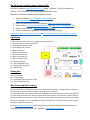
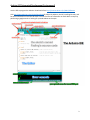
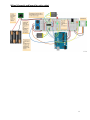
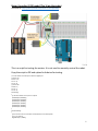
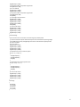
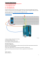
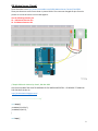
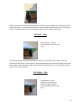
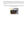
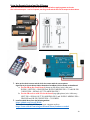
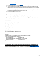
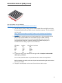
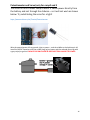
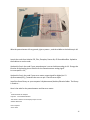
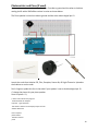
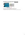
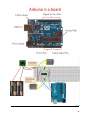
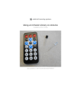
Robotics Camp August 10-14, 2015 Summary Page 2 Arduino Pinouts Page 2 Arduino IDE Page 3 Motor Controller L298D Page 4 UltraSonic Range Finder Page 6 PIR Human Detection Sensor Page 8 Remote Control and IR Sensor Page 12 LED Matrix Display Page 14 Potentiometer Page 15 Photoresistor and Piezo Page 18 Push Button Autonomous Page 21 1 Pin out for our robotics camps- August, 2015 This file is located at www.MDHSrobotics.com under “LeoDuino”. Check this website for updates on this information and to download files for your robot. We used the following videos to discuss important topics: 1. Arduino Overview: https://youtu.be/1NqZuDaN2pc and https://youtu.be/5F054MNB1QI 2. Ohms Law about volts, amps and resistance: https://youtu.be/-mHLvtGjum4 3. How to Solder: https://youtu.be/BLfXXRfRIzY and https://youtu.be/xrVCkEoY_8M 4. How to use a Voltmeter: https://youtu.be/E3elzYUfoe4 5. Check out the following websites for detailed help and examples: http://www.arduino.cc/en/Guide/HomePage And https://learn.adafruit.com/category/learn-arduino Digital pins 0 and 1 not used – they are for serial output and communications 2 – Infrared Sensor for the remote control 3 – Sonic Rangefinder green LED 4 – Sonic Rangefinder red LED 5 – Motor 1 Enable A 6 – Motor 1 Forward int1 7 – Motor 1 Reverse int2 8 – Motor 2 Forward int3 9 – Motor 2 Reverse int 4 10 – Motor 2 Enable B 11 – Sonic Rangefinder Trig 12 – PIR signal out to arduino 13 – PIR LED light Analog pins A0 – Photoresistor A1 – Potentiometer A3 – Push button for autonomous mode A5 - Sonic Rangefinder Echo Wire Colors and Best Practices When possible use the following colors for wires. Red- Positive and Black – Negative/Ground. Green for ground is OK; Yellow or Orange– to lights or outputs; Blue – to Sensors; It is best to keep your color schema consistent throughout your project. Keep wires short in length and run them along a common path. Be sure to keep wires with insulation around the wire. When stripping the wire be sure to not remove too much insulation so that when it is inserted into a component that no bare wire is showing. Correct it immediately if wire is showing as this is the main cause of shorts which damage components permanently. Go to www.MDHSrobotics.com and Arduino summer camp for files and further directions on using your Arduino based robot. Mr. Reynolds – [email protected] 2 Arduino IDE (Integrated Development Environment) Use the IDE to program the Arduino. Download it from http://www.arduino.cc/en/Main/Software Visit http://www.arduino.cc/en/Guide/HomePage for help with Arduino, the IDE, installing libraries, and for basic information on how this all works. You can find a lot of information on each device or topic by performing a google search or looking for youtube videos on the topic. 3 Wiring Schematic and layout for entire robot 4 Motor Controller L293D model (The 16 pin black chip) Instruction at: https://www.youtube.com/watch?v=GumqesVRKyk This is a script for testing the motors. It is not used to remotely control the robot. Copy the script to IDE and upload to Arduino for testing. / connect motor controller pins to Arduino digital pins // motor one int enA = 10; int in1 = 9; int in2 = 8; // motor two int enB = 5; int in3 = 7; int in4 = 6; void setup() { // set all the motor control pins to outputs pinMode(enA, OUTPUT); pinMode(enB, OUTPUT); pinMode(in1, OUTPUT); pinMode(in2, OUTPUT); pinMode(in3, OUTPUT); pinMode(in4, OUTPUT); } void demoOne() { // this function will run the motors in both directions at a fixed speed // turn on motor A digitalWrite(in1, HIGH); 5 digitalWrite(in2, LOW); // set speed to 200 out of possible range 0~255 analogWrite(enA, 200); // turn on motor B digitalWrite(in3, HIGH); digitalWrite(in4, LOW); // set speed to 200 out of possible range 0~255 analogWrite(enB, 200); delay(2000); // now change motor directions digitalWrite(in1, LOW); digitalWrite(in2, HIGH); digitalWrite(in3, LOW); digitalWrite(in4, HIGH); delay(2000); // now turn off motors digitalWrite(in1, LOW); digitalWrite(in2, LOW); digitalWrite(in3, LOW); digitalWrite(in4, LOW); } void demoTwo() { // this function will run the motors across the range of possible speeds // note that maximum speed is determined by the motor itself and the operating voltage // the PWM values sent by analogWrite() are fractions of the maximum speed possible // by your hardware // turn on motors digitalWrite(in1, LOW); digitalWrite(in2, HIGH); digitalWrite(in3, LOW); digitalWrite(in4, HIGH); // accelerate from zero to maximum speed for (int i = 0; i < 256; i++) { analogWrite(enA, i); analogWrite(enB, i); delay(20); } // decelerate from maximum speed to zero for (int i = 255; i >= 0; --i) { analogWrite(enA, i); analogWrite(enB, i); delay(20); } // now turn off motors digitalWrite(in1, LOW); digitalWrite(in2, LOW); digitalWrite(in3, LOW); digitalWrite(in4, LOW); } void loop() { demoOne(); delay(1000); demoTwo(); delay(1000); } 6 Ultrasonic Range Detector Connect the Arduino pins to the following pinouts 3 – Sonic Rangefinder green LED 4 – Sonic Rangefinder red LED 11 – Sonic Rangefinder Trig A5 – Sonic Rangefinder Echo These pins above are not the ones shown in picture below. The reason we changed the pins from the picture are so that all sensors can be used together. This code is meant to trigger the LED outputs when approaching within 20 cm. This distance can be changed in the code. These directions are at http://www.instructables.com/id/Simple-Arduino-and-HC-SR04Example/?ALLSTEPS /* This is a script to use the Ultrasonic Sensor HC-SR04 Ping distance sensor] VCC to arduino 5v GND to arduino GND Echo to Arduino pin A0 Trig to Arduino pin 11 Red POS to Arduino pin 4 Green POS to Arduino pin 3 560 ohm resistor (for 9volt battery) or 330 ohm resistor (for 6 volts from 4 AA batteries) to both LEDs More info at: http://goo.gl/kJ8Gl Original code improvements to the Ping sketch sourced from Trollmaker.com Some code and wiring inspired by http://en.wikiversity.org/wiki/User:Dstaub/robotcar */ #define trigPin 11 #define echoPin A5 7 #define led 4 #define led2 3 void setup() { Serial.begin (9600); pinMode(trigPin, OUTPUT); pinMode(echoPin, INPUT); pinMode(led, OUTPUT); pinMode(led2, OUTPUT); } void loop() { long duration, distance; digitalWrite(trigPin, LOW); // Added this line delayMicroseconds(2); // Added this line digitalWrite(trigPin, HIGH); // delayMicroseconds(1000); - Removed this line delayMicroseconds(10); // Added this line digitalWrite(trigPin, LOW); duration = pulseIn(echoPin, HIGH); distance = (duration/2) / 29.1; if (distance < 20) { // This is where the LED On/Off happens – change this number if you want!!!!! digitalWrite(led,HIGH); // When the Red condition is met, the Green LED should turn off digitalWrite(led2,LOW); } else { digitalWrite(led,LOW); digitalWrite(led2,HIGH); } if (distance >= 200 || distance <= 0){ Serial.println("Out of range"); } else { Serial.print(distance); Serial.println(" cm"); } delay(500); } 8 PIR Motion Sensor (if used) These directions are at http://www.instructables.com/id/PIR-Motion-Sensor-Tutorial/?ALLSTEPS These pins above are not the ones shown in picture below. The reason we changed the pins from the picture are so that all sensors can be used together. Use the following Arduino pins 12 – PIR Human Detector Out 13 - PIR Human Detector LED /*Simple PIR sketch: Written by ScottC, 19th Dec 2013 YOU COULD CHANGE THE CODE TO RESPOND TO THE MOTION DETECTED – AT PRESENT IT TURNS ON THE LED LIGHT ON PIN 13 http://arduinobasics.blogspot.com/ ----------------------------------------------------*/ void setup(){ pinMode(13,OUTPUT); pinMode(12,INPUT); } void loop(){ 9 digitalWrite(13,digitalRead(12)); } Once you have your PIR wired up its a good idea to do a simple test to verify that it works the way you expect. This test is also good for range testing. Simply connect 3-4 alkaline batteries (make sure you have more than 3.5VDC out but less than 6V by checking with your multimeter!) and connect ground to the - pin on your PIR. Power goes to the + pin. Then connect a basic red LED (red LEDs have lower forward voltages than green or blue so they work better with only the 3.3v output) and a 220 ohm resistor (any value from 100 ohm to 1.0K ohm will do fine) to the out pin as shown. Of course, the LED and resistor can swap locations as long as the LED is oriented connection and connects between out and ground Now when the PIR detects motion, the output pin will go "high" to 3.3V and light up the LED! Setting the sensitivity of the device 104 (Left) – Max LED on = 20 sec LED off = 3 sec When you move the 104 labelled potentiometer all the way to the left (max position), the LED will remain on for 20 seconds after movement is detected. The 20 seconds is independent of the other potentiometer (105) setting. When the LED turns off, it will remain off for 3 seconds before the sensor will trigger again from any further movement. 104 (Right) – Min LED on = 1 sec LED off = 3 sec 10 When you move the 104 labelled potentiometer all the way to the right (min position), the LED will remain on for 1 second after movement is detected. When the LED turns off, it will remain off for 3 seconds before the sensor will trigger again from any further movement. 105 (Left) – Max Most sensitive – Detects movement from over 10 steps away. The 105 labelled potentiometer controls the sensitivity of the PIR sensor. When in the left position, the PIR sensor is most sensitive and small amounts of movement will trigger the sensor. It detected my movement (ie a single step to the left of right) from over 10 steps away from the sensor. I was very impressed. 105 (Right) – Min Least sensitive: Need significant movement for sensor to trigger. Detects movement from about 4 steps away. 11 When the 105 labelled potentiometer is twisted to the right, the PIR sensor becomes a lot less sensitive. I needed to take much bigger steps to the left or right to trigger the sensor (about 3 times the size compared to the left position). It also had a lot more trouble detecting movement occurring further away. It only really started to detect my movement when I was about 4 steps away from it. Try this combination with the 104-Right (min) + 105-Left (max), which meant that the sensor would remain on for only a short period of time, and detect any subtle movements in the room. This combination is displayed below: 12 Using the Remote Control and the IR Sensor There are several IR receivers so be sure to wire it carefully before supplying power to the unit. This unit has three pins – one for 5V power, one for ground and the third for an output to the Arduino. 1. Wire up the robot’s motors and the IR for the remote with the correct pinout Signal out to pin 2 on Arduino; GND to Ground on breadboard; VCC to Power on Breadboard a. For the IR on the circuit board (picture on left above) wire it this way: IR PIN 1 LEFT PIN = GROUND and IR PIN 2 MIDDLE PIN = 5V and IR PIN 3 RIGHT PIN = SIGNAL OUT TO ARDUINO PIN 2 b. For the IR receiver with NO circuit board (top right picture) wire it this way: LEFT PIN = SIGNAL OUT TO ARDUINO PIN 2 and IR PIN 2 MIDDLE PIN = GROUND and IR PIN 3 RIGHT PIN = 5V POWER 2. Install the IRLib library from the following website. https://github.com/cyborg5/IRLib/ Directions for installing the library on your computer are here https://learn.adafruit.com/using-an-infrared-library/hardware-needed 13 Installation of the IRLib library (and the other libraries) is as follows: 3. 4. Visit the IRLib page on GitHib. Select the “Download ZIP” button, or simply click this link to download directly. Un-compress the ZIP file after it’s finished downloading. The resulting folder should be named "IRLib-master" and will contain a number of header files, IRLib.cpp and two subfolders containing a user manual and some example sketches. Sometimes in Windows you’ll get an intermediatelevel folder and need to move things around. Rename the folder (containing the .cpp and .h files and the examples and manual subdirectories) to “IRLib” and place it alongside your other Arduino libraries, typically in your (home folder)/Documents/Arduino/Libraries folder. Libraries should not be installed alongside the Arduino application itself. Re-start the Arduino IDE if it’s currently running. Control the movement of the car with the keypad Arrows up, down, left and right to move in those directions. Also, numbers 2 and 8 for up and down; 4 and 6 for left and right; 5 for stop. Optional: To program other buttons on the remote: Determine the remote control’s IR codes that the software will use to run the motors. #include <IRLib.h> //Create a receiver object to listen on pin 2 IRrecv My_Receiver(11); //Create a decoder object IRdecode My_Decoder; void setup() { Serial.begin(9600); My_Receiver.enableIRIn(); // Start the receiver } void loop() { //Continuously look for results. When you have them pass them to the decoder if (My_Receiver.GetResults(&My_Decoder)) { My_Decoder.decode(); //Decode the data My_Decoder.DumpResults(); //Show the results on serial monitor My_Receiver.resume(); //Restart the receiver } } 4. Arduino sketch code for remote controlling of car (install IRremote and IRlib library first) The robot code for moving the car and using the sensors is located at www.MDHSrobotics.com under the Summer Camp Resource Files. The sketch is called “LeoDuino Final Week1” 14 LED MATRIX DISPLAY (8X8) (if used) The instructable is at this website: http://www.instructables.com/id/LED-Matrix-with-Arduino 1. You will need to install a library source folder called LEDcontrolIMS into the My Documents/Arduino/library folder on your windows computer. This is needed to run the code. http://www.instructables.com/id/LED-Matrix-with-Arduino/step2/ArduinoLibrary/ 2. The LED Matrix module has two sets of male header PINs. In this instructable you will only use the input PIN headers that are located closer to the MAX 7219 chip. There are five PINs that must be connected through F/M jumper wires to the corresponding Arduino PINs: I suggest installing the LED Matrix Display into a breadboard and use M/M jumpers into the breadboard. LED Matrix Arduino Color of wire in picture VCC 5V Red GND GND Black DIN D12 Yellow CS D10 White CLK D11 Blue 3. To open this sketch, in the Arduino IDE menu go to File-> Examples->LedControlMS>MakeSpace_ LEDMatrix You can now upload the sketch to your arduino and see what the example does. Before uploading the sketch, make sure that you have selected the right card and serial port for your Arduino 4. Change the text displayed on the screen from within the Arduino script. 15 Potentiometer and Servo (only for camp2 and 3 The servo in the kit needs 1amp to work. It needs power directly from the battery and not through the Arduino – so it will not work as shown below. Try substituting the servo for a light! https://www.arduino.cc/en/Tutorial/Potentiometer Wire the potentiometer left to ground, right to power +, and the middle to the Arduino pin A1 Install the 100UF Capacitor with the anode (long leg) to power and the cathode (short leg with a gray stripe) to ground. CAPACITORS ONLY WIRE IN ONE DIRECTION- ANODE TO POWER. 16 Wire the potentiometer left to ground, right to power +, and the middle to the Arduino pin A1 Launch the code from Arduino IDE, Files, Examples, Starter Kit, 05-ServoMoodCue. Upload to the Arduino to run the code. Update this line in the code if your potentiometer is not on Arduino analog pin A1. Change the location of the Analog pin on Arduino for the Potentiometers analog signal. int const potPin = A1; Update this line in the code if your servo motor output signal for digital pin 13 myServo.attach(13); // attaches the servo on pin 13 to the servo object Install the Servo library on your computer’s Mydocuments/Arduino/libraries folder. The library is found at…. Here is the code for the potentiometer and the servo motor. /* Arduino Starter Kit example Project 5 - Servo Mood Indicator This sketch is written to accompany Project 5 in the Arduino Starter Kit Parts required: servo motor 17 10 kilohm potentiometer 2 100 uF electrolytic capacitors Created 13 September 2012 by Scott Fitzgerald http://arduino.cc/starterKit This example code is part of the public domain */ // include the servo library #include <Servo.h> Servo myServo; // create a servo object //change the potPin to the arduino pin you are connecting it to. int const potPin = A1; // analog pin used to connect the potentiometer int potVal; // variable to read the value from the analog pin int angle; // variable to hold the angle for the servo motor void setup() { myServo.attach(13); // attaches the servo on pin 13 to the servo object Serial.begin(9600); // open a serial connection to your computer } void loop() { potVal = analogRead(potPin); // read the value of the potentiometer // print out the value to the serial monitor Serial.print("potVal: "); Serial.print(potVal); // scale the numbers from the pot angle = map(potVal, 0, 1023, 0, 179); // print out the angle for the servo motor Serial.print(", angle: "); Serial.println(angle); // set the servo position myServo.write(angle); // wait for the servo to get there delay(15); } 18 Photoresistor and Piezo (if used) Photoresistor can be wired in either direction. One side to ground and the other to Arduino analog pin A0 with a 10KiloOhm resistor in series as shown below. The Piezo speaker is wired one side to ground and the other side to digital pin 12. Launch the code from Arduino IDE, Files, Examples, Starter Kit, 06-Light Theremin. Upload to the Arduino to run the code. Don’t forget to update this line in the code if your speaker is not on Arduino digital pin 12. // change the pinout for your piezo speaker const int piezo = 12; /* Here is the code for the program. Arduino Starter Kit example Project 6 - Light Theremin This sketch is written to accompany Project 6 in the Arduino Starter Kit Parts required: photoresistor 10 kilohm resistor piezo 19 Created 13 September 2012 by Scott Fitzgerald http://arduino.cc/starterKit This example code is part of the public domain */ // variable to hold sensor value int sensorValue; // variable to calibrate low value int sensorLow = 1023; // variable to calibrate high value int sensorHigh = 0; // LED pin const int ledPin = 13; // change the pinout for your piezo speaker const int piezo = 12; void setup() { // Make the LED pin an output and turn it on pinMode(ledPin, OUTPUT); digitalWrite(ledPin, HIGH); // calibrate for the first five seconds after program runs while (millis() < 5000) { // record the maximum sensor value sensorValue = analogRead(A0); if (sensorValue > sensorHigh) { sensorHigh = sensorValue; } // record the minimum sensor value if (sensorValue < sensorLow) { sensorLow = sensorValue; } } // turn the LED off, signaling the end of the calibration period digitalWrite(ledPin, LOW); } void loop() { //read the input from A0 and store it in a variable sensorValue = analogRead(A0); // map the sensor values to a wide range of pitches int pitch = map(sensorValue, sensorLow, sensorHigh, 50, 4000); // play the tone for 20 ms on pin for piezo tone(piezo, pitch, 20); // wait for a moment delay(10); } 20 Push button to start autonomous mode (if used) Set the output in (yellow above) to Analog pin 3 with a 10K Ohm resistor. Start a new sketch to look for a signal from A3 to perform a function. I will update some code for you within an hour to run the motors when this button is pressed. 21 22