1
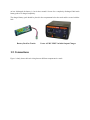
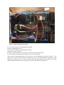
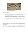
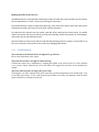
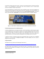
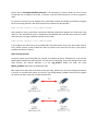
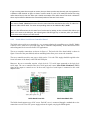
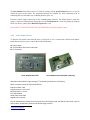
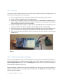
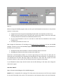
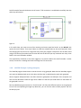
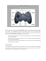
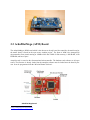
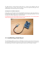
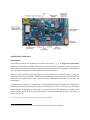
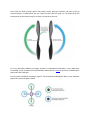
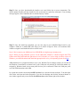
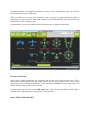
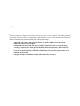
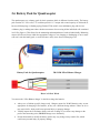
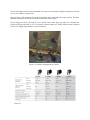
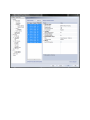
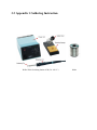
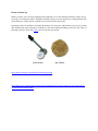
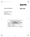
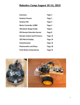
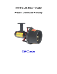
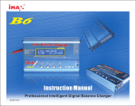
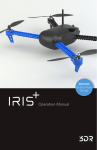
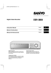
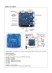
1 SCANIA TRUCKS ......................................................................................................................................... 2 1.1 SUMMARY .......................................................................................................................................................2 1.2 MOTORS .........................................................................................................................................................2 1.3 ELECTRONIC SPEED CONTROLLER..........................................................................................................................3 1.4 BATTERY PACK FOR TRUCKS ................................................................................................................................3 1.5 CONNECTIONS ..................................................................................................................................................4 1.6 PRECAUTIONS ...................................................................................................................................................6 1.7 MANUAL CONTROL WITH A REMOTE CONTROLLER....................................................................................................6 1.7.1 Troubleshooting .....................................................................................................................................10 1.8 MANUAL CONTROL USING MOTES AND LABVIEW ................................................................................................11 1.8.1 Tmote Sky...............................................................................................................................................11 1.8.2 Pololu Micro Serial Servo Controller Board ............................................................................................14 1.8.3 Serial Adapter Board ..............................................................................................................................15 1.8.4 Connection .............................................................................................................................................17 1.8.5 Communication between PC and Mote .................................................................................................17 1.8.6 LabVIEW Example 1 (HelloWorld) ..........................................................................................................19 1.8.7 LabVIEW Example 2 (Using Gamepad) ..................................................................................................21 2 QUADROCOPTER ......................................................................................................................................23 2.1 2.2 2.3 2.4 2.5 2.6 2.7 2.8 3 SUMMARY .....................................................................................................................................................23 ARDUPILOTMEGA (APM) BOARD......................................................................................................................24 ARDUPILOTMEGA SHIELD BOARD ......................................................................................................................25 PROPELLERS ...................................................................................................................................................30 MISSION PLANNER SOFTWARE...........................................................................................................................32 BATTERY PACK FOR QUADROCOPTER ..................................................................................................................38 MANUAL CONTROL WITH A REMOTE CONTROLLER..................................................................................................40 MANUAL CONTROL USING MOTES AND LABVIEW ................................................................................................40 QUALISYS MOTION CAPTURE (MOCAP) SYSTEM ........................................................................................41 3.1 3.2 MOCAP-LABVIEW COMMUNICATION ................................................................................................................49 APPENDIX 1: SOLDERING INSTRUCTION ...............................................................................................................50 1 Scania Trucks Tamiya Scania Truck 1.1 Summary The miniature truck in the Smart Mobility Lab (SML) is a realistic scale model of the Scania R470 (1/14 scale). You have access to a fully assembled truck right from the start, but to build the truck from scratch, you can refer to the corresponding manual (go here1 and browse for Scania R470 Highline). 1.2 Motors Tamiya Scania truck consists of three different motors, as shown in figure ?. RC-car Servo 4519 is used to control the steering of the truck, and HS-645 MG Servo is used to change the gear. The truck has 3 gears. The three available shifts of the gearbox can be selected using the corresponding servo or a certain gear can be selected manually. RS-540SH is responsible for controlling the speed of the truck. Steering (RC-car Servo 4519) Gear Shift (HS-645 MG Servo) 1 http://www.tamiya.com/english/rc/manuals.htm Speed (RS-540SH) You can manually set the gearbox to the lowest speed possible. You can use a wire or other ingenious way of your choice to hold the gear selector shaft in place. In the SML, we used a “cable tie” to hold the gear in the lowest speed. Note that if the “cable tie” is not tightened enough the gear can go to the neutral state easily especially after truck crash. 1.3 Electronic Speed Controller RS-540SH is connected to the ‘Conrad Truck 60WP’ which is an electronic speed controller and is shown in figure 0. Up to two motors can be connected to the speed controller using the plugs with label 2. In the trucks we only use one pair (1 red and 1 black). 1: Battery connection plug (female connector) 2: Connection plug for 2 motors (2 x red, 2 x black) 3: On/off switch 4: Plug for connection to the receiver 5: Indicator LED Disconnect the battery from the speed controller if you are not using the latter. The speed controller can be temporarily switched off using the on/off switch. Electronic Speed Controller (Conrad Truck 60WP) 1.4 Battery Pack for Trucks The trucks use a battery pack for their operation. The battery pack consists of 6 Ni-MH batteries 1.2V each that are connected serially to provide a 7.2V output. There are two kinds of battery packs, 5000 mAh and 5100 mAh, in the smart mobility lab that both can be used in trucks. The battery pack is rechargeable. You can use the Vector AC/DC NX85 charger in the lab to charge the batteries. To do this, change the charging rate to 0.5 ampere and connect the battery pack to the output (note the polarity). Turn on the charger and wait until the green LED turns on. The charging time depends on how discharged the battery is, but it takes around 10 hours for a completely discharged 5000 mAh battery pack to be charged completely. The charged battery pack should be placed in the compartment below the truck and be secured with the lock. Battery Pack for Trucks Vector AC/DC NX85 Variable Output Charger 1.5 Connections Figure ? clearly shows the basic wiring between different components in a truck. Figure 3: Basic connections in a truck 1: 3-wire cable for the servo controlling the gear shift 2: Motor controlling the speed 3: 3-wire cable for the servo controlling the steering 4: Electronic speed controller 5: Battery connection plug for the electric speed controller (female connector) 6: 3-wire cable for connection to the AR6210 receiver or Pololu board Apart from the aforementioned parts, you also need a power distribution cable like in figure ?. The jumper wire is used to feed the power to AR6210 receiver or Serial adapter/Pololu board that we will discuss later. AR6210 receiver is used to control the truck manually using a remote controller. The Serial adapter and Pololu board are also used when you want to control the truck using motes. figure 6: Power Distribution Cable 1.6 Precautions 1. When working with the powered trucks on a table always lift the rear of the vehicle to avoid accidents if the engine starts unexpectedly. 2. If the steering is being tested, keep in mind that at low battery charges, the servo will not move if the front wheels are resting on the ground and the vehicle is stationary. 3. It is recommended to use the lowest gear available in the truck gearbox because the other two gears result in very high speeds in the available range. 1.7 Manual control with a remote controller To be able to test a truck, it can be connected to Spektrum AR6210 receiver and be controlled with Spektrum DX6i remote controller. Spektrum DX6i remote controller is a 6-channel radio system that offers advanced programming features. It uses DSM2 modulation in the 2.4GHz band. Figure 9 shows the DX6i controller. DX6i transmitter runs on 4 AA batteries and you can use rechargeable AA NiMH 1500mAh batteries. To install the batteries, remove the battery door and install 4 AA batteries, noting the polarity of each corresponds with the diagram in the battery holder. Figure x: Spektrum DX6i, Control Identification and Location (Mode 2) Never use the DX5e remote controller with the trucks, turning off this controller is equivalent to sending maximum signals to all the RC channels. For manual control, use the DX6i instead which does not have this problem when turned off. Place a charged battery in the compartment below the truck and secure it with the lock. Connect the battery and electric speed controller. Now you should plug three cables to the receiver (note the polarity). 1. Plug the speed motor (number 6 in figure 3) into the THRO port on the receiver. 2. Plug the steering motor (number 3 in figure 3) into the AILE port on the receiver. 3. (Optional) Plug the gear shift motor (number 1 in figure 3) into the RUDD port on the receiver. figure y: Spektrum AR6210 Receiver Step 1: Binding the Transmitter and Receiver The AR6210 receiver must be bound to the transmitter before it will operate. Binding is the process of teaching the receiver the specific code of the transmitter so it will connect to that specific transmitter. To perform the binding process, follow these steps: 1. Plug the bind plug that came with the receiver into the BATT/BIND port of the receiver. The amber LED should flash indicating the receiver is in bind mode. 2. Move the left stick to the full down position (establishing the fail-safe position). 3. Pull and hold the Trainer switch on the top of the transmitter while turning on the power switch on the transmitter. 4. Keep holding the Trainer switch until the receiver's LED stays on. 5. Remove the bind plug from the receiver. 6. The transmitter and receiver have now been bound. Bind Plug Step 2: Change the Transmitter from Mode 1 to Mode 2 You should make sure that the transmitter is in Mode 2. Mode 2 has the Throttle control on the up and down axis of the left stick and the Elevator controls on the up and down axis of the right stick. Mode 1 has the opposite. This does not affect the Aileron and Rudder controls. 1. 2. 3. 4. 5. 6. 7. 8. Power on the Transmitter. Using the roller, press down once to click, and the Adjust List should appear. Scroll through the list until Model Select is highlighted and click. Scroll through to the Model you wish to configure and click. Scroll through the list until Setup List is highlighted and click. Scroll through the list until you reach Copy/Reset, and click. Scroll down to Reset, and click. The Reset control screen should appear. Switch the Aileron D/R switch at the top right of the Transmitter from position 1 to 0 three times. 9. The hidden mode change menu should appear, scroll to select the mode you wish to use, in this case Mode 2, and click. 10. Scroll to List (top right corner of the screen) and click. Note: These settings only affect the currently selected Model; other stored models are not affected by these changes. Step 3: Adjust the Model Type 1. 2. 3. 4. 5. 6. Power on the Transmitter. Click the roller once. Scroll though until Setup List is highlighted, and click. The Setup List will be displayed. Scroll through until Model Type is selected and click. Select ACRO (with the picture of the plane) and click. Scroll until List in the top right hand corner is highlighted and click. Step 4: Set the Model Name 1. Scroll until Model Name is selected and click. 2. Scroll until the section under Model 1 is selected and click (Model 1 will have a different number depending on which model is selected). 3. Using the scroll wheel and clicking to adjust the characters and position, give the model a name. 4. Once you are happy with the name, scroll through to Ok, and click. 5. Scroll until List in the top right hand corner is highlighted and click. Step 5: Control the Truck Having done the above steps successfully, you can control the truck using the remote controller as following: Throttle is the left stick up and down. Steer is the right stick left and right. Changing gears is the left stick left and right with the RUDD D/R switch in the 0 position. Blinking Red LED on the Receiver The AR6210 features a red LED that indicates the number of holds that have occurred since the receiver was last powered on (a "hold" is from a loss of RF signal connection). The LED will flash the number of holds then pause (e.g., flash, flash, flash, pause, flash, flash, flash, pause indicates three holds occurred since the receiver was last turned on). To experience this yourself, turn the remote controller off by switching the power button. The amber LED on the receiver will turn off, and the red LED starts blinking. Switch the controller on and off again, and you will see the red LED flashes twice. Note that holds are reset to zero (thus the red LED stops blinking) when the receiver is turned off. To do this, you can simply cut the power to the receiver by unplugging the battery. 1.7.1 Troubleshooting The truck moves backwards when it is supposed to go forward Reverse the polarization of the engine. The truck does not move straight at neutral steering Calibrate the steering servo adjustment by changing the lengths of the pivots involved, or if the problem is too serious simply dismount the servo and follow the suggestions presented in the manufacturer manual. The truck neutral speed is no longer the preset value This happens very often, when the truck speed controller goes from interpreting 64 as neutral speed, to do so for other speed values. To fix, set the requested speed back to 64 while you manually reboot the truck speed controller by switching it on and off. 1.8 Manual Control using Motes and LabVIEW To be able to communicate with the trucks from computer, we use wireless sensor nodes (mote). The platform that we use is Tmote Sky. Two motes are used; one attached to the computer (figure a) and the other is attached to the truck (figure b). These two motes create a wireless communication path between the computer and the truck. A LabVIEW program running on the computer sends the actuation data using the aforementioned wireless communication path to the truck to control it. We use PC-mote and Truck-mote to refer to each of the motes. figure a: attached mote to the computer figure b: attached mote to the truck (esme har kodoom o ziresh benevisam) The Truck-mote is plugged into the Serial Adapter Board and serial adapter board is connected to the Pololu Micro Serial Servo Controller Board. In the next sections we will talk about the role of each board in detail, but in nutshell: The Truck-mote receives the actuation data wirelessly from the PC-mote. The Truck-mote sends the actuation data serially to the serial adapter board. The serial adapter board sends the logic-level serial signals to the Pololu board. The Pololu board generates pulse-width modulated control signals for different motors on the truck. 1.8.1 Tmote Sky Tmote Sky is an ultra-low power wireless module for use in sensor networks, monitoring applications, and rapid prototyping. Tmote Sky leverages industry standards like USB and IEEE 802.15.4 protocol to interoperate seamlessly with other devices. Tmote Sky has onboard humidity, temperature and light sensors. It uses MSP430F1611 microcontroller from Texas Instrument, and an on-board radio transceiver CC2420 for wireless communication. As we mentioned before, to control the trucks, we use two different motes. One mote is plugged to the USB port of the base computer (PC-mote) and the other mote is attached to the truck (Truck-mote). The Truck-mote is inserted into the serial adapter board using the 10-pin expansion connector. To be able to do this, you should solder a male header to the 10-pin expansion connector as depicted in figure o. Figure o: A male header is soldered to the 10-pin expansion connector of Truck-mote TinyOS (An operating system for embedded systems) A simple embedded system, with simple functionality, may be controlled by a special purpose program or set of programs with no other software. Typically, more complex embedded systems like Tmote Sky include an OS. Although it is possible in principle to use a general-purpose OS, such as Linux, for an embedded system, constraints of memory space, power consumption, and real-time requirements typically dictate the use of a special-purpose OS designed for the embedded system environment. A significant number of operating systems have been designed from the ground up for embedded applications. The two examples are TinyOS2 and Contiki3. In the Smart Mobility Lab we use TinyOS to program the Tmote Sky motes. Program the Motes Download the Truck_TinyOS from the following link and extract it. http://kth-wsn.googlecode.com/svn/trunk/kth-wsn/apps.tutorials/GettingStarted/TinyOS_Files/ This folder contains two sub-folders (PC_mote and Truck_mote). PC_mote folder contains the TinyOS code for the mote attached to the computer, and Truck_mote contains the TinyOS code for the mote attached to the truck. 2 3 http://www.tinyos.net/ http://www.contiki-os.org/ Please refer to GettingStartedWithTinyOS.pdf in the repository for further details on how to install TinyOS and how to program the motes. In chapter 4 you will find instructions on how to program a mote. For instance in Ubuntu you can navigate to PC_mote folder, and use the following command to program the PC-mote using node Id 7. We assumed the mote is attached to /dev/ttyUSB4. make telosb install.7 bsl,/dev/ttyUSB4 Now navigate to Truck_mote folder, and use the following command to program the Truck-mote using node id 7. We assumed the mote is attached to /dev/ttyUSB0. We used the same node Id for both motes, but you can assign a different number to each mote. make telosb install.7 bsl,/dev/ttyUSB0 If you program the motes using the provided code, then both motes will use the same radio channel. Thus, you do not have to worry about that. But if you want to use more than one pair in your project, read the next section carefully. Radio Channel Selection Tmote Sky motes use the IEEE 802.15.4 protocol to send data wirelessly. IEEE 802.15.4 in the 2.4 GHz band supports 16 different radio channels. PC-mote and corresponding Truck-mote should use the same radio channel. The channel definition is in the app_profile.h header file under the name RADIO_CHANNEL and accepts a hexadecimal value. Both codes for PC-mote and Truck-mote use the same app_profile.h file, thus if you change a parameter in that file, it will affect both motes. As a result if you change RADIO_CHANEEL to 0x13 and re-program the motes then both motes will use radio channel 0x13. If you are using more than one pair or motes, then you have to make sure that each pair is programed in a different radio channel as figure u shows. In other words if a pair of PC-mote/Truck-mote are using radio channel 0x13, then the other pair should use another free radio channel like 0x15. Otherwise there may be collisions between the transmitted packets of the two Truck-motes. You can attach a label to each mote to differentiate them from each other. For example you can label one mote as Truck, 7, 0x16 which means that this mote should be attached to the truck, its node Id is 7 and uses radio channel 0x16. The other corresponding mote can be labeled as PC, 7, 0x16. You can also differentiate the PC-mote from Truck-mote by looking at the on-board LEDs. When you attach a PC-mote to the USB port, the red and green LEDs will light up. In contrast, when you attach a Truck-mote to the USB port, all LEDs are off. 1.8.2 Pololu Micro Serial Servo Controller Board The Pololu micro serial servo controller is a very compact solution for controlling up to eight RC (Radio Control) servos. Each servo speed and range can be controlled independently. It has three status LEDs and an integrated level converter for RS-232 applications. The servo controller connections are shown in figure c1. The back side of the board which is shown in figure c2 has all of the ports labeled, and two mounting holes allow you to secure the controller. The servo controller needs its own power, which can be 5-16 volts. This supply should be applied to the lower-left corner of the board, at the VIN and GND pins. Moreover, the server controller requires a logic-level (0-5 V) serial input connected to the logic-level serial input. The servo controller takes this serial input and creates Pulse-Width Modulated (PWM) signal at the output to control servos. In the trucks, logic-level serial input is connected to the serial adapter board. Pololu Board Front Side Pololu Board Back Side The Pololu board supports up to 8 RC servos. Each RC servo is connected through a standard three-wire connection: two wires for a DC power supply and one for signal, carrying the PWM signals. The first channel of the Pololu (servo 0) is used for steering, and the second channel (servo 1) is used to control the speed of the motor. The remaining channels are available for future expansions such as controlling the servo that takes care of shifting between gears, etc. Protocol selection jumper selects one of the communication protocols. The default mode is when the jumper is open (no shorting block) and in this case the Pololu protocol is used. By placing the shorting block over the two jumper pins, Mini SSC II protocol is used. In the SML we use the Pololu mode, thus you should make sure that the jumper is open. 1.8.3 Serial Adapter Board To interface the Pololu board with the mote’s serial port we use a custom board called serial adapter board that provides the pins to connect the Pololu and the mote. J1: Power Supply J2: To Polou Micro Serial Servo Controller P1: To Tmote Sky Serial Adapter Board PCB Serial Adapter Board PCB (after soldering) We ordered the PCB from Cogra Company4. The board specification is as following: Motor controller board: 45.39mm X 26.025mm Number of Drills <500 Copper thickness = 35 micron Board thickness = 1.6mm Two-sided boards Solder mask: both sides Legend print: top layer You can download the Gerber file of the board from the following URL (the Gerber file format is the de facto industry standard for printed circuit board image transfer). 4 http://www.cogra.se/ <link> You can also get the schematic file from the following URL. To open the .sch files you can use Eagle program by Cadsoft. <link> Figure 8: Schematic of the serial adapter board At the next step you should solder components in Table 1 to the board. We ordered the components from Farnell Company5 and you can find the Farnell order code in the last column. Refer to appendix 1 to get more information about soldering and how to use the soldering equipment in the SML. Qty 2 1 1 1 1 1 1 1 2 1 1 5 Type Capacitor Capacitor Capacitor Header with 2 contacts Header with 5 contacts Socket Resistor Resistor Non-inverting buffer Regulator Regulator http://se.farnell.com/?CMP=ffp-sm-flag-se Value 1u 10u 22u F-1X02-SIP-100-40 F-1X05-SIP-100-40 TMOTE_SKY_BIGHDR 10k 16k MC74VHC1GT50DT LP38692MP AP1117E50G-13 Name C1, C2 C3 C4 J1 J2 P1 R1 R2 U1, U2 U3 U4 Farnell order code 1650988 1612276 1432346 1593411 1593414 3419216 1738972 9332677 1652259 1008056 1825292 1.8.4 Connection Until now you become familiar with the role of Tmote Skye, Pololu board and serial adapter board. The next step is to connect them in the correct order. 1. Place a charged battery in the compartment below the truck and secure it with the lock. 2. Attach the Tmote Sky board to the serial adapter board. 3. Connect the serial adapter board to the Pololu board using a 3-wire female to female cable as shown in figure 8 (note the polarity). The purpose of this wire is to send power (red and black wires) and signal (white wire) to the Pololu board. 4. Plug the steering motor (number 3 in figure 3) into the servo 0 port on the Pololu board. Also plug the speed motor (number 6 in figure 3) into the servo 1 port on the Pololu board. 5. Connect the jumper wire of the power distribution cable (figure 6) to the serial adapter board. Then connect the other terminal of power distribution cable to the electric speed controller. 6. Now, connect the power distribution cable to the battery. The yellow LED on the Pololu board should turn on. Figure 8 1.8.5 Communication between PC and Mote We use a serial forwarder to send data from computer to the PC-mote. You can find Java-based and Cbased serial forwarder in the TinyOS installation folder. We use the C-based serial forwarder which is in tinyos-x/support/sdk/c/sf. Please refer to comm2pc.pdf manual to learn more about the concept of serial forwarder and how it can be used. Issue the following command to run the serial forwarder. We assume that you are using Cygwin in Windows and the PC-mote is connected to the port COM15 of the PC. DO NOT close the Cygwin window after you run this command. sf 9003 COM15 telosb By running the above command, a TCP server process is created in the computer which listens on port number 9003 (as shown in figure r). Any TCP client can connect to this server and sends data to it. The serial forwarder forwards the received data to the PC-mote attached to COM15. 1.8.6 Communication Link (Summary) Figure 1 shows the communication link between the PC and truck clearly. Labview creates a TCP client process that connects to the TCP server. The TCP server has been created by the serial forwarder (SF). Thus a TCP connection will be established between the LabVIEW and the SF. Labview sends the actuation data through this TCP connection to the SF, and SF forwards the data to the PC-Mote which is attached to say COM7 of the PC. The PC-Mote sends the actuation data wirelessly (using IEEE 802.15.4 protocol) to the Truck-Mote. Both PC-Mote and Truck-Mote should be programmed in the same wireless channel. Truck-Mote receives the actuation data and sends the correct signals to the truck. 1.8.7 LabVIEW Example 1 (HelloWorld) This labVIEW program shows how to control the truck by sending actuation data to it. Figure 1 shows the front panel of the program. 1. Destination Id: Shows the node Id of the Truck-mote. Recall that, you can set the node Id of a mote when you program it. 2. Steering: This slider controls the steering of the truck. Moving the slider to the left, turns the front wheels to the left and moving the slider to the right, turns the front wheels to the right. Slider data type is unsigned byte (U8), thus the value range is [0,255]. 3. Motor Speed: This slider controls the speed and direction of back wheels. Moving the slider to the left, turns on the back wheels in reverse and moving the slider to the right, turns on the back wheels in forward. Slider data type is unsigned byte (U8), thus the value range is [0,255]. 4. OpenSF Error: if any error occurs in opening the serial forwarder, you can see the error message and the error code here. 5. WriteSF Error: if any error occurs in writing data to the serial forwarder, you can see the error message and the error code here. Figure 1: Before running the labVIEW program make sure that you have followed the instructions in the previous sections. To summarize: 1. Program both motes using the corresponding TinyOS code in the repository (section 1.8.1). 2. Attach the correct motes to the PC and the truck. Connect the battery to the truck and make sure the yellow LED is turned on the Polulo board (section 1.8.4). 3. Run the serial forwarder on the PC to be able to send data from labVIEW to the PC-mote (section 1.8.5). 4. Re-read the precautions in section 1.6. Now change the ‘Destination Id’ according to the node Id of the Truck-mote, and run the labVIEW program. As soon as you run the labVIEW program, LEDs on both motes start blinking. Pay attention to the LEDs on the Truck-mote. Blinking blue LED means that data is received successfully from the PC-mote. Blinking green LED means the data is written to the UART port. Note that in serial forwarder window, it is normal to get writing error every once in a while, but if it shows too many ‘write failed’ then something is wrong with the PC-mote connection. To resolve this you can disconnect the PC-mote and plug it again to the USB port. Then close and re-open the serial forwarder window. In most severe case you should reboot your computer and try again. If you followed the above steps and still cannot see the LEDs blinking on the mote, then change the motes and try again. How does it Work? Figure 2 shows the block diagram of the labVIEW program. OpenSF sub-vi is responsible for creating a TCP client process that connects to the TCP server (created by the serial forwarder). We use this TCP connection to send actuation data to the serial forwarder. Serial forwarder forwards the data to the PC-mote. If TCP connection is established successfully then the while loop will execute. Figure 2: In the while loop, we create an array from steering and motor speed and send it to the WriteSF. We repeat this every 100ms. Thus every 100ms we send the actuation data to the serial forwarder. Note that changing the loop interval to a high value may make your program unresponsive. On the other hand using a low value may overwhelm the PC-mote with lots of data and you may encounter too many ‘write failed’ in the serial forwarder window. The responsibility of WriteSF, as the name suggests, is to write the data to the serial forwarder. In other words, it constructs a message and sends it through the TCP connection. 1.8.8 LabVIEW Example 2 (Using Gamepad) This labVIEW program shows how to control the truck using gamepad. Note that this labVIEW program only works in Windows (and not in Unix) due to the fact that it needs DirectX to work with gamepad. We use Logitech Gamepad F310 in the SML. Attach the gamepad to the USB port of the computer and wait until the Windows installs the right driver. Make sure that the X|D mode switch on the bottom of the gamepad is set to X. Run the labVIEW program and click on ‘Check Control’ tab. Play with different buttons on the gamepad to see if the corresponding LED lights up. Moreover, you can see the values of both joysticks and also the 8-way D-pad. Now click on Control tab and use the Control Mode to select your desired input method. By default Control Mode is set to Manual which means that gamepad is disabled and the labVIEW program behaves exactly like the previous example. You can use the slider to control the steering and motor speed. Change the Control Mode to Gamepad to enable the gamepad. - Use the left joystick and move it in X-axis to control the steering. You can see the steering slider moves in the front panel. Use the RT button to move the truck forward. You can increase the forward speed by putting more pressure on the RT button. Use the LT button to move the truck backward. You can increase the reverse speed by putting more pressure on the LT button. How does it Work? The program simply reads the value from the gamepad and re-scales it in range [0,255] using a simple linear conversion. For instance, moving the left joystick in X-axis produces values in [-32768, 32767] range. We re-scale it to [0, 255] and use it as the steering value. 2 Quadrocopter ArduCopter Quadrotor 2.1 Summary The ArduCopter is a multirotor Unmanned Aerial Vehicle (UAV) development platform based on a design by Jani Hirvinen. ArduCopter contains an autopilot from DIY Drones and an airframe from jDrones. It has six degrees of freedom, three rotational and three translational. There are several models of ArduCopter with different number of propellers, the most common are: tri-, quad-, hexa- and octa-rotors. The ArduCopter in the smart mobility lab is ‘ArduCopters quad’ that we call it quadrocopter and is shown in figure 4. The quadrocopter is fully assembled, but to build it from scratch, you can refer to the corresponding manual6. The span from motor to motor is about 60 cm. The motors are of electrical, brushless type and have a RPM/Volt rating of 850. They can rotate at a maximum rotational velocity of about 11000 RPM and generate a thrust of almost 1 kg per motor using a standard 10x45 propeller. The four motors are powered by a Lithium-Ion Polymer (LiPo) three-cell battery with a nominal voltage of 11.1V and a rated capacity of 2200 mAh. One speed controller is used for each motor to generate the switched AC current needed by the brushless motors and thereby control the motors rotational velocity proportional to the applied input signal. The main part of an ArduCopter is shows in figure 3. It basically consists of two boards that are attached to each other. The board in the bottom is ArduPilotMega or ARM in short and the board at the top is ArduPilotMega Shield. In the following, we will explain the role of each board in detail. 6 http://code.google.com/p/arducopter/wiki/ArduCopter 2.2 ArduPilotMega (APM) Board The ArdupilotMega (APM) board which is also known as the red board, the controller, the main board or the master board, is based on the open source Arduino project7. The heart of APM is the Atmega2560 microcontroller from Atmel running at 16MHz which has 256kB of flash memory, 8 kB SRAM, 4 kB EEPROM, and lots of pins! Autopilot code is stored on the aforementioned microcontroller. The hardware and software are all open source. The firmware is already loaded, but the autopilot software must be loaded onto the board by the user. It can be programmed with the ‘Mission Planner Software’. ArduPilot Mega Board 7 http://code.google.com/p/arduino/ The APM board has a built-in hardware failsafe that uses a separate circuit (multiplexer chip and ATMega328 processor) to transfer control from the RC system to the autopilot and back again. It also includes ability to reboot the main processor in mid-flight. Attaching GPS to the APM Board (Optional) Finally, attach your GPS module as shown below (MediaTek module shown). It goes in the connector on the APM board, not the similar one on the IMU shield (that one, which says "No GPS!", is an I2C connector for the optional magnetometer or other I2C sensor). In the SML we do not use a GPS module, since we only use the Quads indoor. We use Qualisys Motion Capture system (MoCap in short) to track the mobility of quads. 2.3 ArduPilotMega Shield Board The ArduPilotMega Shield is also known as APM Oilpan, the shield, the sensor board, the blue board or the slave board. This board features a large array of sensors and it is designed to fit on top (or bottom) of the ArduPilot Mega CPU board, creating a total autopilot solution when a GPS module is attached. ArduPilotMega Shield Board Accelerometer Accelerometers measure acceleration in one to three linear axes (x, y, z). A single axis accelerometer can measure acceleration in whichever direction it is pointed. This may be good for a rocket, an impact, a train or other scenario where the device really moves in one basic direction. Knowing the acceleration and time, you can use mathematics to find the distance traveled by the object. There are fewer and fewer single and double axis accelerometers on the market because a triple axis accelerometer can do so much more. Thanks to low manufacturing costs the three axes accelerometers are not much more expensive than single or double. On the APM shield board, there is one triple axis accelerometer. Acceleration due to gravity is a constant and is in fact measurable using an accelerometer. When placed parallel to the ground, acceleration due to gravity would only be “felt” by one axis. However, when tilted, this acceleration would appear as components of two (or three) axes. The measured acceleration can be used to calculate the tilt of an object by subtracting the current accelerometer data from a value that you know to be zero tilt 8. Accelerometers are used mainly to measure acceleration and tilt. 8 You can get an idea of how to use an accelerometer to measure tilt here and here. Gyroscope Gyroscopes measure angular velocity in α, β, γ (see image below). In other words, a gyroscope tells you how fast something is spinning about an axis. Gyroscopes can be used to help with stabilization and well as changes in direction and orientation. Unlike accelerometers, gyroscopes do not have a fixed reference, and only measure changes. XY Gyros: Z Gyro: Gyroscopes are used to measure angular velocity and orientation. Pressure Sensor Contrary to what you may suggest, pressure sensor has nothing to do with weather. Instead, it is there to enhance the GPS navigation (dead-reckoning, slope detection, etc). Pressure sensors can add considerably to the accuracy of navigation systems when GPS signals are weak or temporarily obscured. Interested reader can refer here for more detailed information. Covering the barometric pressure sensor (Optional) Because the APM board is open and exposed to the airstream in ArduCopter, the props spinning around it can create a strong draft that can distort the altitude sensor readings. So for multicopter use, it's best to cover the barometric sensor input with a breathable wind shield. Part of a cotton pad (like a makeup removal pad) is perfect (a bit of breathable foam would work, too). Just tape it over the sensor as shown: Magnetometer (Compass) When in motion, ArduPlane gets its heading data from the GPS module. But to get accurate heading data on the ground you need a magnetometer. A magnetometer will also improve navigation in the air. In the following we will explain in detail why we need magnetometer and how you can install it on the board. The orientation of the aircraft and the direction the airframe is moving (not necessarily the same) are an important input for navigation and stabilization in ArduPlane. Without a magnetometer, the orientation of the plane is calculated using successive GPS fixes plus the inertial sensors: Sensor drift is compensated by reference to the GPS ground course, as that should fix the current compass point for the nose of the plane (assuming no wind or opposite rudder). With a magnetometer, we no longer have to rely on the GPS ground course to correct for sensor drift, and the orientation of the plane becomes more accurate. If you fly with a cross wind, either manually or under full autopilot control, then the magnetometer will provide more accurate fixes for sensor drift. HMC5843 magnetometer is usually used on the APM shield board. This is a 3-axis digital compass board based on the Honeywell's HMC5843. Communication with the HMC5843 is achieved through an I2C interface. Two different ways can be used to attach this magnetometer, using a cable or mount directly on the board. Using a cable: You can attach the HMC5843 magnetometer to the APM shield's I2C sensor port, which looks like a GPS connector but says "No GPS". Figure 5 shows this. One reason to do this is you intend to daisy-chain other I2C sensors to your board. Mount directly: If you don't plan on using the 4-pin I2C connector on the shield for anything else, you can mount the magnetometer directly on top. Figure 5 shows this. In the SML, we use this method. Attach magnetometer using a cable Mount magnetometer directly on the board How to enable it: https://code.google.com/p/ardupilot-mega/wiki/MagAPM1 Sonar Sensor http://trollmaker.com/article3/arduino-and-hc-sr04-ultrasonic-sensor http://www.tautvidas.com/blog/2012/08/distance-sensing-with-ultrasonic-sensor-and-arduino/ Flash Memory 16 MB data logger chip among other things needed for UAV and Robotics applications, including three-axis angular rotation and accelerations sensors, absolute pressure and temperature sensor, 16 MB data logger chip among other things. Moreover, different sensors (GPS, Magnetometer, Sonar sensor, etc.) are incorporated into it that we will talk about them later. Autopilot code is stored on the aforementioned microcontroller. The autopilot handles both stabilization and navigation, and it can be used for different rotor crafts such as helicopters or other types of multirotors. It also supports a “fly-by-wire” mode that can stabilize an aircraft when flying manually under RC control, making it easier and safer to fly. 2.4 Propellers The propellers are attached on top of the motors. A smaller prop is easier to speed up and slow down whereas a large prop takes a long time to change speeds. Basically the motor needs to be matched to the propeller that is used. If the propeller forces it to turn too slowly the motor will over heat and fail. In the SML we use propellers with 10 × 4.5 in size. The first number is the diameter of the prop in inch. The larger the number the larger the prop. The second number is the pitch of the prop in inch, essentially the angle of the twist in the prop. The higher this number the bigger the bite the prop takes out of the air. A larger prop, either in diameter or pitch, or both, puts more load on the motor, but is also more efficient in general. Smaller props are generally used for speed, larger props for higher thrust at lower speed. You'll need two kinds of props (puller and pusher). Pusher props go clockwise and puller props go counterclockwise. To differentiate the two, check the letter after the prop size. The pusher prop has letter R at the end and puller prop has no letter (or letter P) at the end. It's a very good idea to balance your props; vibration is a multicopter's worst enemy. If your copter arms are shaking, it's just a matter of time before disaster strikes! Here's a video on how to do it, balancing the props with a little clear tape. Prop orientation should be according to figure 5. The prop should be blowing air down, not up. Attach the props to the motors as figure 6 shows. 2.5 Mission Planner Software Installing Software and Firmware Step 1: Go to the Arducopter Downloads page at the following address and download the latest version of the Mission planner installer. It will be called MissionPlanner-x.x.xx.msi in which x shows the current version. Note that the mission planner software is frequently updated. https://code.google.com/p/ardupilot-mega/downloads/list Step 2: Once you have downloaded the installer, run it and follow the on screen instructions. The mission planner installer will also install all of the system drivers required by arducopter, if any warning messages appear, select "Install this driver software anyway” button. Step 3: Once the install has completed, you can now plug in your ArduPilot Mega board to your computer. APM uses a miniB USB cable. Plug it in as shown in figure 8. Wait a few moments while windows recognizes and installs the drivers for the board. Note 1: Don’t connect your APM board via a USB HUB as it might not get enough power. Note 2: When you plug APM into your PC via the USB cable, Windows 7 should recognize the FTDI USB-to-serial chip and install the right drivers, but if it doesn't or if you're using an earlier version of Windows, you should download and install the appropriate driver for your Operating System from here. APM should now be recognized and show up in your Windows Device Manger (which you can find in the Windows Control Panel) as shown below (your COM port will probably be a different number; it's assigned by Windows based on how many other devices you've connected). That's the COM port you'll use in all USB interactions with APM. It's a good idea to make sure that the Set RTS on close box is checked for the serial port. To do this rightclick on the serial port and select Properties. Go to the Port Settings and click the Advanced button. A new window appears and you can find the Set RTS on close on the bottom right of the windows. Step 4: Now you can open the mission planner software, but do not click the connect button, you must first load the correct firmware. To do this click on the firmware icon, and select the relevant code you want to load. In our case you should click on the ArduCopter Vx.x.x Quad. The Mission Planner will autodetect what kind of board you have, download the latest code from the Internet and load it on your APM board. When you click on the relevant icon to load the code, a progress bar shows the firmware update is progressing, you may also notice many lights flashing on your ardupilot board. Once the firmware has loaded the bar will be completely green. Congratulations, you have now loaded the latest firmware onto your ardupilot mega board. First-time APM Setup Once you have loaded the firmware onto your board, the next step is to run the First time setup. This is done with the mission planner that you installed earlier. On the mission planner make sure you have selected the correct COM port and baud rate 115200, and click on Connect in the top right corner. The Mission Planner will now connect via MAVLink. Go the Firmware tab, and click on the APM setup button. This will open up a dialog box like figure c that will walk you through the basic setup process, described below. Step 1: Radio Calibration (RC) Step 2: Set flight Mode You can choose different flight modes that you can change while you are flying with your RC transmitter (channel 5). Toggle your channel 5 switch to see which mode you are currently in (indicated by the green highlighted mode). Step 3: ArduCopter Level Select Plus Click on Calibrate Accelerometer Step 4: Configure additional hardware Step 5: The code required to control the aircraft is open source and it is easy to modify. The ArduCopter also comes with a software called “Mission Planner” that allows the user to set the controller constants, each channel’s minimum and maximum PWM limits, among other things. 1. Attach the USB cable. It will power the board. The mini-USB port is on the ? board. 2. upload the software into the quad 3. Calibrate the throttle, pitch. The battery should be attached because we need the mote working to send the data. Each channel should be calibrated separately. In the LabVIEW, send 0 then 127 and back to 0. By this you specify a range! 4. It seems that the IMU will be calibrated automatically every time the quad is armed (a red blinking led shows this). 5. Change all modes to stabilization (it has other modes like acrobatic). 2.6 Battery Pack for Quadrocopter The quadrocopters use a battery pack for their operation which is different from the trucks. The battery pack consists of 3 Li-Po cells 3.7V each that provide 11.1V output with a rated capacity of 2200 mAh. It has two different plugs. A discharge plug (Female XT60) with 2 wires and balance plug with 4 wires. A balance plug is nothing more than a breakout connector for accessing all the individual cells contained in a Li-Po (figure x). This allows for the monitoring and manipulation of each cell individually. Balancing ensures all cells are always within the appropriate voltage so over charging or discharging of one or more cells won’t ruin the battery pack, or worse become a safety issue from overcharging a cell. Battery Pack for Quadrocopters iMAX B6 LiPro Balance Charger How a 3s LiPo is Wired You can use the ‘LiPro Balance charger’ in the lab to charge the batteries. Always use a Lithium specific charger only. Chargers meant for Ni-MH batteries only are not appropriate for charging Li-Po batteries, as they use a different charge scheme. Failure to do so may result in fire, which could cause personal injury or property damage. Visually inspect the Li-Po battery before each use or charge. If you observe any damage to the pack or the connecting wires, DO NOT charge or use the battery. Do not disassemble or modify the battery pack in any way, doing so may result in fire, which could cause personal injury or property damage. Charging Process To charge the Li-Po battery pack follow these instructions: 1. Connect the input power cable (11-18V DC) to the charger. 2. Connect the discharge plug (note the polarity) and the balance plug of battery pack to the correct connections of the charger. 3. Now you should select the appropriate program suitable for the Li-Po battery. To do this, press the Batt. Type key and select LiPo BATT. Then press the Start/Enter key to apply the selection. 4. Charging rate should be 2.2A and voltage should be 11.1V(3S). To change a parameter, press Start/Enter key to make it blink and alter the value using Inc or Dec key. Never charge the battery higher than a 1C charge rate (1C is 1 times the capacity of the battery). For example, a 2200mAh battery should be charged at 2.2 amps. 5. Put the battery in a battery bag such as a RFI “LiPo-Safe” (figure ?). 6. Press Start/Enter key for more than 3 seconds. Then press Start/Enter key again to confirm and start charging. Never leave the battery unattended while charging. Always monitor the battery during the charge process. Be very careful not to short the lead wires of the battery, as this could cause a fire. Shorting could occur during soldering of connectors or while cutting off connectors. Be sure to completely insulate one pole of the connector while soldering the other. Also, if cutting off a connector, cut only one wire at a time to avoid shorting the battery. If a short should occur, even a very brief short, place battery in a safe, non-flammable area and observe for 15 minutes. 2.7 Manual control with a remote controller During the first flights of a new airplane, it’s recommended to check the red LED hold indicator. If it’s flashing, it’s important to optimize the installation (move or reposition antennas) until no hold occurs. On later flights, the LED Hold Indicator can be used to confirm RF link performance. http://www.rctruckandconstruction.com/showthread.php?t=3535 2.8 Manual Control using Motes and LabVIEW 3 Qualisys Motion Capture (MoCap) System In the SML we use Motion Capturing System (short MoCap) from Qualisys. The system does a multi view 3D construction of passive IR markers. The system is based on the fact that if a point in space is seen from at least two different viewpoints with calibrated cameras of known position, the position of the point in 3D can be calculated. The cameras are sensitive in the infrared spectrum and they’re equipped with infrared flash. The objects to be tracked are equipped with passive markers (figure 9). Passive markers are small reflective balls that reflect the IR light from the cameras flash. The image is thresholded on the cameras and position and size of the markers are calculated. This information is sent via Ethernet to a computer running Qualisys Track Manager (QTM) software. The QTM tries to match the markers seen in different images and calculates the positions of the markers. The markers are seen in the camera image as small bright dots (figure 10). Figure 9: Reflective marker Figure 10: Image of markers seen by one camera Oqus System Setup We use 12 different Oqus cameras in the SML to cover the whole field. Three cameras are installed in each corner (facing downward) that is shown in figure 11. Cameras are connected in daisy-chained fashion. 2 out of 12 cameras are Oqus 3+ and the rest are Oqus 4. Refer to figure 12 for more information on each camera type. Oqus 3+ has a new sensor with some new features and improvements like more light-sensitivity, improved image, high-speed video mode. Light-sensitivity: The Oqus 3+ is at least 50% more light-sensitive than the other Oqus models. This means that you can see markers at a longer distance with the same exposure and threshold setting as on the 3-series. Or you can use smaller markers at the same distance as you could for the 3-series. Note: The default exposure time setting for Oqus 3+ is 200 microseconds, because of the increased light sensitivity. The increased light sensitivity also means that it is easier to see the markers at higher frequencies, because you can use a shorter exposure time. Improved image: The image has less static and dynamic noise compared to the other cameras. Therefore the marker threshold can often be lower than on the other camera types. Sensor High-speed mode: The Oqus 3+ has a special sensor mode where you only use a fourth of the pixels but still keep the field of view. The camera can then capture at 1764 Hz with the sensor resolution of 648×512, slightly larger than the 1-series resolution. Figure 11: Cameras configuration on a corner Figure 12: To start using the system, you should make sure that the power adapters are connected to the electricity plug. Qualisys DHCP Server (QDS) A powerful PC in the SML is dedicated for working with the QTM software. It has a Core i7 3.4 GHz CPU with 8 GB of RAM that runs 64-bit Windows 7. Two network interface cards are present in this PC. One is connected to the KTH network and is assigned a public IP address of 130.237.50.61. The other is used only for the cameras and is assigned a private IP address of 192.168.254.1. The QTM software is already installed on this PC. An important component of the QTM software is Qualisys DHCP server called QDS. QDS assigns IP addresses to the Oqus cameras. An IP address for each camera is required to be able to communicate with them over the Ethernet network. According to the Qualisys documentations, the DHCP server will only give IP addresses to Oqus cameras so it will not disturb the KTH network. But it is recommended to separate the camera network from the KTH network. That’s why we used two different network interface cards for the cameras and the KTH network to completely isolate the two. Before you connect the Oqus camera system, you should make sure that the QDS is running and that the network interface setting are correct. The recommended setup is to use static IP on the Oqus network. Use the wizard to setup the network interface. Step 1: Right click on the QDS icon in the status toolbar and select Oqus configuration wizard. Step 2: Select Configure a network interface... and click Next. Step 3: The list will show all enabled network interfaces on the computer. Select the last interface (Oqus) and click Next. This interface is used for the Oqus cameras. Step 4: The wizard shows how it will change the selected interface. Click Next to continue. Step 5: Click Finish to close the wizard. Oqus startup sequence To start using the system, you should make sure that the cameras are connected to the PC and QDS is running. Step 1: Connect the power supply and the green LED on the front will blink twice. Step 2: After a few seconds the startup bar below is shown. If the bar stops at two-thirds then the Oqus is waiting for an IP-address. The reason is probably either a missing connection to the computer or that QDS is not running. Step 3: When the camera has an IP-address the display will show an image similar to one below. The Oqus will first synchronize to other cameras, during that process the clock is blinking and there is a spinning plus sign instead of the letter M or S. Wait until the clock stopped blinking and the display shows M or S. The M or S on the display stands for Master respectively Slave. This is only to show which camera that is sending a synchronization pulse to the other cameras. Oqus Display The Oqus camera has a large graphical OLED display and three LEDs on the front to inform the user of the current status of the camera. The display shows, among other things, the camera number and the number of markers currently seen by the camera. Note: The display will be turned off when the camera enters stand-by mode, i.e. if the camera has not been in use for 2 hours. Start a preview in QTM to light up the display again. 1. Measurement status indicator Green light Yellow light Flashing green light Flashing yellow light The camera is ready to start a measurement The camera is measuring Waiting for trigger to start measurement Waiting for trigger to switch from pre-trigger to post-trigger measurement 2. Error indicator A red light indicates that an error has occurred. The LED is blinking when a software error occurs and is lit constantly if a hardware error occurs. 3. IR receiver The IR receiver is used for synchronization with certain active markers. It detects modulated light with a frequency of 33 kHz and is sensitive to light with wavelengths between 800 and 1100nm. 4. Synchronization status During the synchronization phase this symbol is flashing. When the camera is synchronized with the master camera in the system it becomes stable. 5. WLAN indicator This symbol is displayed when the WLAN of the camera is activated. 6. Master/Slave indicator An M indicates that the camera is master for the system and by that controls for example internal synchronization. An S indicates that the camera is a slave. The indicator can also be a rotating + sign, which means that the camera is looking for the Master camera. 7. Camera number The area to the right usually shows the camera number that the camera has in QTM. The camera number can be changed with the Reorder tool in the 2D view window. This number is stored in the camera so it is shown at the next camera startup. 8. Marker area During a marker measurement this area shows the number of markers currently seen by the camera. When the camera is idle or is collecting video, this area shows ’-----’. 9. Text area This area is used for scrolling text messages, for example during startup. Qualisys Track Manager (QTM) Software In the 2D view you can see the captured view from each camera during the measurement. Calibration Process Remove reflective objects You should make sure that the field is free of any unwanted markers or reflective objects as they cause problems for the calibration. By looking at the 2D view of the QTM software, you can easily check if any unwanted markers are present and try to hide them from the cameras. Three types of markers (it was written in the Jonas factor) Matlab and LabVIEW page 27 of user manual 3.1 MoCap-LabVIEW Communication if you run the labview and it asked for license! You should install the appropriate software on the main pc. go to help -> about -> license and add the license here 3.2 Appendix 1: Soldering Instruction Weller WS 81 Soldering Station 95W (50 - 450 °C) Solder Handle Oxidized Tip Before you start, wet your tip by applying some soldering on it. If the soldering absolutely refuses to stay on the tip, it's because the latter is oxidized, probably because your iron stayed on too long without being used. Don't try to solder with an oxidized tip, you won't obtain a good result. Fortunately, there are products, sold under the name of "tip activator" which allows you to recover from this situation and clean in depth an oxidized tip. Note that oxidation/cleaning cycles have the effect of gnawing at the tips. Check this video on how to use the tip activator. Tip Activator Dry Cleaner http://www.yoctopuce.com/EN/article/soldering-tutorial http://electronics.stackexchange.com/questions/1980/whats-the-proper-soldering-iron-temperaturefor-standard-031-60-40-solder