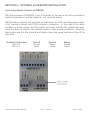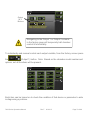
1
PLANT P T GROW WTH C CHAMB BERS OPE ERATIO ONS M MANUA AL Forr -22, -5 50, -75 5 Seriess 7300, 7301, 7302, 7303, 7 7 7304, 7 7305, 7 7306 PO Box 715 etta, OH 4 45750 Marie 800-6 648-3042 740-373 3-6809 Fax 7 740-374-3 3760 www..caronproducts.com m servicce@caron nproducts.com Dear Valued Customer: Thank you for purchasing CARON Products & Services equipment. We appreciate your business and look forward to being your preferred supplier of controlled environment equipment products in the future. At CARON, we are committed to continuous quality improvement. Our goal is to supply our customers with highly reliable equipment at a fair price. In order to openly monitor our performance, we would appreciate your feedback on our products and services. If you have questions, or any suggestions for improvement based on the installation or operation of the equipment you have purchased, please contact our service department at [email protected] or 740-373-6809. Thanks again for your business! 7300 Series Operations Manual Rev F 06-03-15 Page 2 of 88 TABLE OF CONTENTS Section 1 – Warranty.......................................................................................5 Section 2 – Equipment Overview...................................................................8 Section 3 – Installation .................................................................................10 Unpacking Choosing a Location Preliminary Cleaning Installing the Port Stopper Installing the Shelves Leveling the Unit Connecting the Drain Line Connecting Electrical Power Connecting the Fluorescent Lighting Section 4 – Optional Accessory Installation ..............................................15 Connecting Alarm Contacts (ALRM302) Connecting the CO2 Supply (CO2C302) Connecting the Water Supply (HUMD302, HUMD303, HUMD308) Connecting Analog Outputs (OUTP301 / OUTP302) Installing Drain Water Pump (PUMP301) Section 5 – Operation ...................................................................................20 Using the Keypad Learning the Screen Saver Controlling the Fluorescent Lighting Setting the Light Cycle Timer Status of the Light Cycle Changing the Temperature Set-point Changing the Humidity Set-point Changing the CO2 Set-point Section 6 – Optional Accessory Operation ................................................37 Operation of the Data Logging System (DLOG301) Operation of the Front 6” Mounted Recorders (RCDR316 / RCDR317) Operation of the Front 10” Mounted Recorders (RCDR318 / RCDR319) 7300 Series Operations Manual Rev F 06-03-15 Page 3 of 88 Section 7 – Calibration .................................................................................49 The Calibration Screen Calibrating the Temperature Calibrating the Humidity Calibrating the CO2 Calibrating the Lights Calibrating Optional Chart Recorders Section 8 – Alarms ........................................................................................55 Alarm System Overview Snoozing the Speaker Muting the Speaker Changing Alarm Set-points Section 9 – Alerts ..........................................................................................62 Alert System Overview Resetting the Maintenance Screen Section 10 – Info............................................................................................63 Info System Overview Section 11 – Advanced Features .................................................................66 Setting the time & day Locking the controls Changing the passcode Factory menu & troubleshooting Section 12 – Preventative Maintenance ......................................................80 Section 13 – Specifications ..........................................................................81 Section 14 – Electrical Schematics .............................................................82 Section 15 – Troubleshooting ......................................................................84 Section 16 – Spare Replacement Parts .......................................................85 Appendix A – Declaration of Conformity ....................................................87 7300 Series Operations Manual Rev F 06-03-15 Page 4 of 88 SECTION 1- WARRANTY INFORMATION EQUIPMENT LIMITED WARRANTY Please review this section before requesting warranty service. At CARON, one of our primary goals is to provide customers with high levels of personal service and top quality products, delivered on time, backed by technical service and supported for the life of the product. Before contacting us for warranty service, please be aware that there are repairs that are not covered under warranty. WARRANTY DEFINED Caron Products & Services, Inc. (herein after CARON) hereby warrants that equipment manufactured by CARON is free from defects in materials and workmanship when the equipment is used under normal operating conditions in accordance with the instructions provided by CARON. COVERED: Parts and labor for a period of one (1) year from date of shipment. Any part found defective will be either repaired or replaced at CARON’s discretion, free of charge, by CARON in Marietta, OH. Parts that are replaced will become the property of CARON. If CARON factory service personnel determine that the customer’s unit requires further service CARON may, at its sole discretion, provide a service technician to correct the problem, or require the return of the equipment to the factory or authorized service depot. CARON will have the right to inspect the equipment and determine the repairs or replacement parts necessary. The customer will be notified, within a reasonable time after inspection, of any costs incurred that are not covered by this warranty prior to initiation of any such repairs. NOT COVERED: Calibration of control parameters. Improper installation; including electrical service, gas and water supply tubing, gas supplies, room ventilation, unit leveling, facility structural inadequacies or ambient conditions that are out of specification. Cost of express shipment of equipment or parts. Any customer modifications of this equipment, or any repairs undertaken without the prior written consent of CARON, will render this limited warranty void. CARON is not responsible for consequential, incidental or special damages; whether shipping damage or damages that may occur during transfer to the customer’s point of use. When the equipment is signed for at the customer’s site, ownership is transferred to the customer. Any damage claims against the shipping company become the responsibility of the customer. Repairs necessary because of the equipment being used under other than normal operating conditions or for other than its intended use. Repair due to the customer’s failure to follow normal maintenance instructions. Parts considered consumable; including: light bulbs, filters, gases, etc. Damage from use of improper water quality. Damage from chemicals or cleaning agents detrimental to equipment materials. Force Majeure or Acts of God. This writing is a final and complete integration of the agreement between CARON and the customer. CARON makes no other warranties, express or implied, of merchantability, fitness for a particular purpose or otherwise, with respect to the goods sold under this agreement. This warranty cannot be altered unless CARON agrees to an alteration in writing and expressly stated herein shall be recognized to vary or modify this contract. Ohio Law governs this warranty. 7300 Series Operations Manual Rev F 06-03-15 Page 5 of 88 EQUIPMENT INTERNATIONAL LIMITED WARRANTY Please review this section before requesting warranty service. At CARON, one of our primary goals is to provide customers with high levels of personal service and top quality products, delivered on time, backed by technical service and supported for the life of the product. Before contacting your distributor for warranty service, please be aware that there are repairs that are not covered under warranty. WARRANTY DEFINED Caron Products & Services, Inc. (herein after CARON) hereby warrants that equipment manufactured by CARON is free from defects in materials and workmanship when the equipment is used under normal operating conditions in accordance with the instructions provided by CARON. COVERED: Parts for a period of two (2) years from date of shipment. Any part found defective will be either repaired or replaced at CARON’s or their authorized representative’s discretion. Parts that are replaced will become the property of CARON. If CARON or their authorized representatives determine that the customer’s unit requires further service, CARON or the representative may, at its sole discretion, provide a service technician to correct the problem, or require the return of the equipment to the an authorized service depot. CARON or their authorized representative will have the right to inspect the equipment and determine the repairs or replacement parts necessary. The customer will be notified, within a reasonable time after inspection, of any costs incurred that are not covered by this warranty prior to initiation of any such repairs. NOT COVERED: Calibration of control parameters. Improper installation; including electrical service, gas and water supply tubing, gas supplies, room ventilation, unit leveling, facility structural inadequacies or ambient conditions that are out of specification. Cost of express shipment of equipment or parts. Any customer modifications of this equipment, or any repairs undertaken without the prior written consent of CARON, will render this limited warranty void. CARON and their representative are not responsible for consequential, incidental or special damages; whether shipping damage or damages that may occur during transfer to the customer’s point of use. When the equipment is signed for at the customer’s site, ownership is transferred to the customer. Any damage claims against the shipping company become the responsibility of the customer. Repairs necessary because of the equipment being used under other than normal operating conditions or for other than its intended use. Repair due to the customer’s failure to follow normal maintenance instructions. Parts considered consumable; including: light bulbs, filters, gases, etc. Damage from use of improper water quality. Damage from chemicals or cleaning agents detrimental to equipment materials. Force Majeure or Acts of God. This writing is a final and complete integration of the agreement between CARON and the customer. CARON makes no other warranties, express or implied, of merchantability, fitness for a particular purpose or otherwise, with respect to the goods sold under this agreement. This warranty cannot be altered unless CARON agrees to an alteration in writing and expressly stated herein shall be recognized to vary or modify this contract. Ohio Law governs this warranty. Caron Products & Services, Inc. PO Box 715 · Marietta, OH 45750 740-373-6809 7300 Series Operations Manual Rev F 06-03-15 Page 6 of 88 INT TERNA ATIONA AL SYMBOLS S AND D DEFIN NITION NS ? Help H i In nformation n Warning W of hazardou us area Warning W off hot surfa ace Warning W of dangerou us electric c voltage Ea arth (grou und) protective co onductor WA ARNIN NGS Lo ocal government may m require e proper d disposal 7300 0 Series Operrations Manua al Re ev F 06-03- 15 Pag ge 7 of 88 SECTION 2 – EQUIPMENT OVERVIEW Congratulations! You have just purchased the latest technology in plant growth chambers. Before using the equipment, familiarize yourself with key components of the product and thoroughly read this manual. Replaceable air intake filter behind bezel (refrigerated models) 7” Full Color HMI Power Switch Illuminated CARON Logo Adjustable Sliding Shelf Left Side Access Port Right Side Access Port Door Handle Temperature (& Humidity) Sensors behind panel Note: Solid doors shown, glass doors optional 7300 Series Operations Manual Rev F 06-03-15 Page 8 of 88 SECTION 2 – EQUIPMENT OVERVIEW – CONTINUED Day / Time Actual Temperature Status Bar Setpoint Menu Speaker Lockout icon Settings Menu Light Cycle Menu Parameter Display Zones Actual Light Current screen indicator (Home Screen) Navigation Pane (indicates menu depth) (Settings Screen) 7300 Series Operations Manual Rev F 06-03-15 Submenu categories Page 9 of 88 SECTION 3 – INSTALLATION Unpacking Your new unit has been thoroughly packaged to avoid shipping damage. However, the unit should be fully inspected upon arrival before signing for receipt. If the package has visual damage, notes should be made on the freight bill and signed by the delivery company. In the event of concealed damage after the unit is uncrated, keep the carton and packaging material. Call the shipping company within 7 days of receipt, request inspection and retain a copy of the inspection report. Caron provides full on-site installation services for all models. Our installation services guarantees the proper set-up and startup of all equipment. Please contact the Service Department at 740-373-6809 or [email protected] for details. For detailed instructions on how to safely remove the chamber off the shipping pallet, see document located on the chamber. Choosing a Location This product weighs in excess of 700 pounds. Ensure that sufficient resources are available to safely move the product. To ensure proper operation, the unit must be located on a firm level surface, capable of supporting approximately 1,000 pounds. The unit should be located in an 18°C – 25°C ambient area and where there is no direct airflow from heating and cooling ducts as well as out of direct sunlight. Allow four inches of clearance on all sides of the product to allow for connections and airflow. Depending on user set points, these units may not need a drain. Drains are recommended at temperatures below 15°C. Units with optional humidity control (HUMD302, HUMD303 & HUMD308) need a water source and drain. The unit requires a dedicated electrical connection. Power requirements vary depending upon the chamber model, see Connecting Electrical Power section. 7300 Series Operations Manual Rev F 06-03-15 Page 10 of 88 Choose a location where these facilities are, or can be made available. If a water source or a drain is not available, contact CARON customer service and ask about our CRYS102 product line or click this web link for information on the product: http://www.caronproducts.com/65 Preliminary Cleaning Your new plant growth chamber was thoroughly cleaned prior to leaving the factory. It is recommended however, to disinfect all interior surfaces with a general purpose laboratory cleaning agent prior to using the product. After cleaning, dry all interior components with a sterile cloth as necessary. Installing the Port Stoppers The unit has an access port built into each side of the cabinet. The ports are designed to allow customer access for equipment validation and for installation of other equipment inside the chamber. These ports should be sealed with the provided rubber stoppers to allow the chamber to function properly. Install the stoppers provided in the port on each side of the unit. Installing the Shelves Each new 7300 Series plant growth chamber includes perforated stainless steel shelves. Each shelf requires two shelf channels for installation. The left and right shelf tracks are the same. Prior to installation, take time to consider what the size of the product being placed in the chamber will be and set the shelf spacing accordingly. Additional shelving can be purchased through CARON customer service if necessary. The chamber should be empty when being moved. To install the shelf channels insert the rear tab on the shelf channel into the rear wall on the side wall of the chamber. Then insert the front tab into the front pilaster. Push the entire shelf channel towards the rear of the unit and snap it down into place. Each shelf is capable of supporting a uniformly distributed load of 50 pounds. The maximum chamber capacity (stationary) is: 250 lbs / 113kg (1-door), 500 lbs / 226kg (2door) and 750 lbs / 339kg (3-door). 7300 Series Operations Manual Rev F 06-03-15 Page 11 of 88 Do not have multiple loaded shelves out simultaneously or the chamber may tip. Leveling the Unit Place a level on the middle shelf of the incubator. Adjust the feet until the unit sits level left to right and front to back. Even if the unit is level without adjustment, the leveling feet should still be lowered to avoid the cabinet moving while opening and closing the outer door & prevent a flat spot from forming on the casters. Connecting the Drain Line When using a pressurized water source, failure to connect the unit to a drain could result in facility flooding. The chamber drain connection is located in the bottom middle of the back of the chamber. A 1/2” tube fitting and tubing are supplied in the unit parts kit. Slide the tubing into the drain connection. Pull on the tubing after installation to make sure it is tight. Route the drain tubing to a local floor drain. The drain line relies on gravity to remove water from the chamber. The drain line must remain below the chamber to drain properly. Kinks or elevations in the drain line above the cabinet drain will not allow the chamber to drain. If a local floor drain is not available, a variety of accessories are available through CARON customer service. These accessories can also be viewed at www.caronproducts.com. For non-humidified chambers operated above 15°C, a drain is not needed. Install the 1/2” plug into the drain connection. 7300 Series Operations Manual Rev F 06-03-15 Page 12 of 88 Connecting Electrical Power Connect each chamber to a grounded circuit. Failure to do so could result in electrical shock. The unit requires a dedicated electrical outlet. See table below for model specific power required and connection. Model # -22-1 -22-2 -22-3 -50-2 -50-3 -75-2 -75-3 Power Requirements 115V, 60Hz, 16A FLA 230V, 60Hz, 10A FLA 230V, 50Hz, 8A FLA 230V, 60Hz, 16A FLA 230V, 50Hz, 16A FLA 230V, 60Hz, 20A FLA 230V, 50Hz, 20A FLA Plug Connection NEMA 5-20 NEMA 6-15 CEE 7/7 NEMA 6-20 CEE 7/7 NEMA L6-30 IEC60309-32A When the required electrical connection is available, plug the provided power cord into the unit and the electrical outlet. 7300 Series Operations Manual Rev F 06-03-15 Page 13 of 88 Connecting the Fluorescent Lighting Chambers with fluorescent lighting have light banks consisting of either six or eight lamps each. The light banks are suspended to the shelf underside. The lights shipped fully installed in place and wired from the factory. Model 7302 does not have the light bulbs installed in the light fixtures from the factory, they are shipped separately and have to be installed. See the Operations or Maintenance sections of the manual for more details. Lights should only be used in a non-condensing environment. Lights are bright. Avoid looking directly at them. Use protective eye wear or serious eye damage may occur. Light banks Model 7303-50 shown here. Other models will vary slightly 7300 Series Operations Manual Rev F 06-03-15 Page 14 of 88 SECTION 4 – OPTIONAL ACCESSORY INSTALLATION Connecting Alarm Contacts (ALRM302) With the purchase of ALRM302, a set of terminals on the rear of the unit is provided to monitor temperature, humidity (optional), co2 (optional) alarms. With the alarm contacts, the terminals provided allow for a NO (normally open) output, a NC (normally closed) and COM (common) connection. In the event of an alarm condition or power failure, the NO contact will close, and the NC contact will open. Once the alarm is cleared, the contacts return to their normal conditions. Insert the appropriate wire into the terminal and tighten down the screw terminal on top of the connector. Terminal Connection N/O to C N/C to C 7300 Series Operations Manual Unit off Closed Open Normal Open Close Rev F 06-03-15 Alarm Closed Open Page 15 of 88 Connecting a CO2 supply (CO2C302) High concentrations of carbon dioxide can cause asphyxiation. The use of CO2 monitors and alarms is recommended for areas where CO2 can collect. The CO2 gas supply should be 99% pure and should not contain a siphon tube. Gas pressure to the unit must be regulated to 15-20PSI. Failure to do so could cause tubing to burst. The CO2 supply should be 99% and not have siphon tubes. CO2 pressure should be regulated to 15-20 psi. CO2 tank regulators can be purchased through CARON customer service. Once the cylinder regulator is installed, connect the outlet of the regulator to the hose barb fitting using the tubing and clamps provided. An inline HEPA filter is provided to remove any contaminants in the CO2 gas supply. Check the connections closely for leaks. If the unit is equipped with a built in gas guard system, there will be 2 gas inlets. Each of the inlets should be connected to an individual gas tank as described above. 7300 Series Operations Manual Rev F 06-03-15 Page 16 of 88 Connecting the Water Supply (HUMD302, HUMD303 & HUMD308) To ensure proper operation, distilled or deionized water is required as a supply on units that have humidity control. If these water sources are not available contact CARON customer service. Use only distilled or deionized water with a resistivity between 50K-CM and 1M-CM and a pH of greater than 6.5. Using water outside this range will void your warranty. Do not use water that contains chloramines. Chloramines can damage internal rubber gaskets resulting in leaks. A water inlet fitting on the back of the unit and ¼” black tubing are provided to connect the water supply to the chamber. Connect an appropriate water supply to the fitting. Incoming line pressure should be regulated to not exceed 80 psi. Tubing to water inlet If a Condensate Recirculator water recycling system was purchased as a water supply, refer to its user’s manual for proper installation of the water supply. 7300 Series Operations Manual Rev F 06-03-15 Page 17 of 88 Con nnecting Analog Outputs O (OUTP301 ( 1, OUTP3 302 & OU UTP303) With the purrchase off OUTP30 01, OUTP P302 or O OUTP303, the con ntrols are equipped d with h analog outputs. o A set of te erminals are a provid ded on the e back of the unit tto connec ct to a analog outtputs. Analog Output Connec ctions Ana alog outp puts as either milliamps (4-20mA) o or voltage e (0-5V) signal output that represents each e of th he display yed tempe erature (a and humid dity) value es. Thesse options s can n be used for conne ection to in n-house data d acquisition, reccorder, orr alarm syystem. Para ameter Temp perature Humidity CO2 C Volta age 0–5V 0–5V 0–5V Currentt 4-20 mA A 4-20 mA A 4-20 mA A Corresp ponding V Value 0 – 100 °C 0 – 100 %rh 0–2 20 %CO2 2 nnect shie elded wire es to the appropriat a te signal tterminals: I(+) for ccurrent (mA) or V(+) Con for vvoltage (D DC). For both curre ent and vo oltage outtputs, CO OM(-) is co ommon terminal. 7300 0 Series Operrations Manua al Re ev F 06-03- 15 Page e 18 of 88 Installing Drain Water Pump (PUMP301) Pump Outlet to Sink or Floor Drain Pump Inlet from Chamber Drain Reservoir with Internal Level Switch In applications where a floor drain is not available and a CARON water recycling system is not being used, a drain pump can be purchased to pump any excess condensate from the chamber to a local sink or drain. The pump is located near the middle of the back of the chamber. Connect the supplied tubing from the pump to the sink / drain. The tubing may be run vertically into a ceiling but should not exceed 15 feet height. The pump is equipped with a small reservoir on the bottom of the pump with an internal level switch that will automatically turn the pump ON when it is full to drain the water out of the reservoir and into a floor or sink drain. 7300 Series Operations Manual Rev F 06-03-15 Page 19 of 88 SECTION 5 – OPERATION With the chamber properly installed and the appropriate utilities connected, the power switch on the right side top wrap can be turned on. Within a few minutes, the temperature and humidity will begin to approach set-points. Here is an overview of the home screen. Day / Time Actual Temperature Status Bar Speaker Setpoint Menu Lockout icon Settings Menu Parameter Display Zones Light Cycle Menu Actual Light 7300 Series Operations Manual Rev F 06-03-15 Page 20 of 88 Using the Keypad This control system uses a numeric keypad to enter all parameter values. Similar to a calculator, this allows quick and precise entry of values. When any numeric value button is pressed, the keypad display will pop up over the current display. Range of variable Parameter Description Header Keypad Display Escape Clear Negative sign Enter Decimal The Parameter Description Header tells what parameter is being changed. The Keypad Display shows allowable values of the parameter being changed (initially) and displays the entered value (when a button is pressed). The Escape “Esc” button aborts the entry and returns to the previous screen without changing the value. The Clear “Clr” button erases the value that you have entered. After you have entered the value that you want, pressing the Enter “Ent” button and the new value will take affect. This also closes the keypad window. Other keypad buttons include a decimal point button and negative button. If an invalid numeric button is pressed such that it would create an entry above the parameter’s range, the entered number will not display. For example, if the temperature set point range is 5.0 to 70.0, pressing ‘8’ followed by an ‘0’, only the ‘8’ will display. If an invalid entry is made with an entry below the range (such as a ‘4’ followed by the ‘Ent’ button), then the entry will clear and the range will be re-displayed. 7300 Series Operations Manual Rev F 06-03-15 Page 21 of 88 Learning the Screen Saver To ensure long product life, the touchscreen display will automatically enter screen saver mode after 15 minutes. At this time, the screen will be completely blank (ie. black). The illuminated Caron logo (see Equipment Overview section) shows that the unit is powered on and functioning. To wake-up the touchscreen, simply press anywhere on the touchscreen and the main screen will display. If the unit has an alarm condition, the touchscreen will not go into screen saver mode. If an alarm condition occurs while in screen saver mode, the display will automatically wake up and display the alarm. Controlling the Lighting The plant growth chamber comes with a fluorescent lighting system (except model 7306 is LED lighting) used to simulate day and night testing. This is a 24 hour cycle that can be programmed with separate temperature and humidity (optional) set-points that correspond with the lights on (day) and lights off (night). The set-points can also be made the same if continuous conditions are needed throughout the light cycles. Each fluorescent light bank is mounted on the underside of a shelf. LED lights are mounted on the sides. The shelves are adjustable in height. Humidity (optional) Daytime Setpoint Temperature Lights CO2 (optional) Nighttime Setpoint 7300 Series Operations Manual Rev F 06-03-15 Page 22 of 88 Humidity (optional) Temperature Lights CO2 (optional) Nighttime Setpoint Active Light Banks Timer Setup Continuous Light Start / Stop Timer The Light Cycle screen has parameters that can be set up for the light cycle. Hour Minute AM or PM Lights On Start Time Lights Off End Time Gradual Light 7300 Series Operations Manual Rev F 06-03-15 Page 23 of 88 The Timer Setup screen allows users to setup lights “on” start time and lights “off” end time. The Gradual Light button (option) simulates 30 minutes of sunrise and sunset light conditions. The Active Light Banks (button) lets you choose which light banks that you want “on” or “off” during the light cycle. This feature can also be used when the light cycle is setup for Continuous Light and the light timer is not required. (Not available on all models) Start / Stop Timer When the Start / Stop Timer (button) is active, the light timer will run the cycle based on the parameters that were setup. An icon appears in the status bar letting the user know that the Light Cycle is running (during this cycle the Continuous Light feature is disabled). 7300 Series Operations Manual Rev F 06-03-15 Page 24 of 88 Continuous Light The Continuous Light (button) lets the light banks be on all of the time. When this feature is enabled, the features of the time based light cycle are disabled. Setting the Light Cycle Timer Light Cycle Menu Screen shown with optional humidity and co2 To set the Light Cycle, press the the screen. 7300 Series Operations Manual (Light Cycle) button on the right side of Rev F 06-03-15 Page 25 of 88 To set up the Light Timer press the of the screen. Hour Minutes (Timer Setup) button on the left side AM or PM Lights On Start Time Lights Off End Time Gradual Light Press the Lights On Start Time hour button and the enter the hour that you want the lights to come on. Finish by pressing 7300 Series Operations Manual (Ent) key. Rev F 06-03-15 Page 26 of 88 Then press the “minutes” button to set the minutes. To setup AM/ PM, Press will toggle back and forth. (AM /PM) button and the words for AM and PM Repeat process for setting up Lights Off End Time. Select Gradual Light button to simulate sunrise and sunset light conditions. (optional) Go back to the previous screen by pressing 7300 Series Operations Manual Rev F (Light Cycle) button. 06-03-15 Page 27 of 88 From this screen press the Active Light Banks (button) Select which light banks are to be on during the light cycle. Note: This feature is only available on chambers with multiple independent light banks and is not available on single door units (models -22). Light Bank layout on -75 and -50 units 7300 Series Operations Manual Rev F 06-03-15 Page 28 of 88 Go back to the previous screen by pressing (Light Cycle) button. To activate the Light Cycle Timer press the Start / Stop Timer button. 7300 Series Operations Manual Rev F 06-03-15 Page 29 of 88 Status of the Light Cycle The light cycle is programmed to automatically change lights, temperature and humidity (optional) over a 24 hour period. The Light Cycle Info screen is intended to provide a comprehensive visual illustration of the Light Cycle settings and current conditions. When the Light Cycle is running, the status of the cycle time can be displayed by pressing the Light Cycle icon that is in the Status Bar. Light Cycle The Light Cycle Info screen displays information regarding the light cycle, start time, end time, light banks etc. This icon is only displayed in the Status Bar when the Light Timer is active and during the “lights on” time. 7300 Series Operations Manual Rev F 06-03-15 Page 30 of 88 Current time ‘Day’ start time ‘Night’ set points ‘Day’ set points Light bank status ‘Night’ start time When Light Cycle is active the Light Cycle Info icon appears in the Status Bar. Press this icon button and Light Cycle Info screen will appear displaying information about the Light Cycle and if it is near completion of the cycle. To return to the home screen press the Close Window button, or wait 15 seconds and the screen will return to the home screen. 7300 Series Operations Manual Rev F 06-03-15 Page 31 of 88 Changing the Temperature Set-point The steps below walk through an example of changing the temperature set point from 30.0 °C to 20.0 °C. This example shows humidity control as well (model 7000 series only). Here is the display of the home screen. Setpoint Button Actual Temperature To set the temperature set-point, press the side of the screen. (Setpoint) button on the right Temperature Setpoint Button On Plant Growth Chambers there is a Daytime and Nighttime Temperature setting Once the Setpoint screen appears, press the (Temperature Setpoint) button. (In this example the temperature set point initially has a value of ’30.0’; this will vary with different initial set point values.) 7300 Series Operations Manual Rev F 06-03-15 Page 32 of 88 Keypad A temperature setpoint window will appear. Enter the temperature setpoint by using the keypad. For a set point of 20, press (‘2’), then (‘0’), followed by the (Enter) key. Correct any mistakes with the (Clear button) and reenter the value. Once the Enter key has been pressed, the pop-up keypad disappears and the screen returns to the Setpoint display with the new value of 20.0 °C in the temperature set point button. Home Temperature Setpoint Button To change the parameters for the Nighttime setpoints, press the Night Setpoint button and repeat same steps for Changing Temperature Set-point Press the 7300 Series Operations Manual (Home) button to return to the main screen. Rev F 06-03-15 Page 33 of 88 Changing the Humidity Set-point (HUMD302, HUMD303 & HUMD308 only) The steps below walk through an example of changing the humidity set point. Here is the display of the home screen. Setpoint Button Actual Humidity To set the humidity set-point, press the of the screen (Setpoint) button on the right side Humidity Setpoint Button Once the setpoint screen appears, press the (Humidity Setpoint) button. Keypad 7300 Series Operations Manual Rev F 06-03-15 Page 34 of 88 Enter the new humidity set point on the keypad as desired and press when complete. (Enter) Home Button Press the 7300 Series Operations Manual (Home) button to return to the main screen. Rev F 06-03-15 Page 35 of 88 Changing the CO2 Set-point (CO2C302) The steps below walk through an example of changing the CO2 set point. Here is the display of the home screen. Setpoint Button Actual CO2 To set the CO2 set-point, press the the screen. (Setpoint) button on the right side of CO2 Setpoint Button Once the setpoint screen appears, press the (CO2 Setpoint) button. Keypad 7300 Series Operations Manual Rev F 06-03-15 Page 36 of 88 Enter the new CO2 set point on the keypad as desired and press complete. (Enter) when Home Button Press the 7300 Series Operations Manual (Home) button to return to the main screen. Rev F 06-03-15 Page 37 of 88 SECTION 6 – ACCESSORY OPERATION Operation of the Data Logger (DLOG301) The DLOG301option provides the customer with a means of logging data electronically for viewing at a later date. Logged variables are temperature, humidity, CO2 and light intensity (but only if the chamber is equipped with those features.) All data is timestamped with year, month, day of the month, hour, minute, 24 hour time (ISO 8601 format). This data is stored internally in the chamber in non-volatile memory. Data is logged every 5 minutes (provided the chamber is on), more than 10 years of data can be stored in memory. If the internal memory fills up, new data overwrites the oldest data. Continuous writing to the flash drive necessitates a high quality industrial grade device. Use only the flash drive provided by Caron (or equivalent: single level cell memory, wear leveling algorithms, error correcting code). File name format is Data start YYYY_MM_DD HH_MM” (hours in 24 hour time) When the chamber is on, the chamber’s history data is being stored even when a flash drive is not inserted in the USB port. This data may be retrieved anytime using the provided USB flash drive. Here are the methods for retrieving data: Continuous logging of data Insert the flash drive into the chamber’s USB port. When first inserted, it creates a .csv file called ‘DATA START’ with the current date and time in the file name. At 5 min intervals, the chamber’s process values are appended to the file. (The file will get as large as the flash drive will allow which would be years of data.) 7300 Series Operations Manual Rev F 06-03-15 Page 38 of 88 USB icon USB icon appears in in Status bar indicating that data is being written to flash drive. To retrieve the data press the ‘Eject’ button. The flash drive is then inserted into a computer for uploading the data. Upon re-insertion of the flash drive, a new .csv file is created, even if the old file is still present. File name nomenclature is “Data Start YYYY_MM_DD HH_MM” with hours in military time. History Retrieval Auto Export Select the ‘Auto Export’ feature on the USB menu screen. Insert the flash drive into the chamber’s USB port. A new .csv file is automatically created on the flash drive with all the stored history data. The file name nomenclature is “Data End YYYY_MM_DD HH_MM”. 7300 Series Operations Manual Rev F 06-03-15 Page 39 of 88 All Data There is also an ‘All Data’ feature to indicate if the upload should include all data (since the unit has been used) or just the history data since a flash drive was inserted last. An ‘Info’ button will appear in the status bar warning the user not to remove the flash drive while the data is being uploaded. The length of time to upload the file will depend on the file size. When the ‘Info’ button disappears from the status bar, press the ‘Eject’ button to safely remove the flash drive. Now the data can be uploaded to a computer for viewing. Using the Continuous Logging of Data method nothing on the touch screen has to be setup. However using the History Retrieval method of data will require going into the USB screen to select either the ‘Auto Export’ or ‘All Data’ buttons before inserting flash drive into USB port. To select the ‘Auto Export’ and ‘All Data’ buttons. Settings Button Press the 7300 Series Operations Manual (Settings) button. Rev F 06-03-15 Page 40 of 88 Setup Button Press the (Setup) button. USB Button Press the (USB) button. When the ‘All Data’ button is selected this will retrieve all of the data from when the chamber was first turned on, up to the current time when flash drive was removed from USB port. 7300 Series Operations Manual Rev F 06-03-15 Page 41 of 88 When the ‘Auto Export’ button is selected this will retrieve the data from the previous time when data was retrieved, up to the current time when flash drive was removed from USB port. USB flash drive icon Info button Eject button When flash drive is inserted into the USB port a ‘USB flash drive’ icon and flashing ‘Info’ button appears in the status bar indicating that the data is being downloaded to the flash drive. Once ‘Info’ icon stops flashing select the ‘Eject’ button. Wait until the USB icon disappears to safely remove the flash drive from the USB port. Note: Press the Eject button before removing the flash drive from the chamber, otherwise there could be the risk of corrupt data. Here is a graphic to illustrate how the data retrieval works. 7300 Series Operations Manual Rev F 06-03-15 Page 42 of 88 Operation of Front Mounted 6” Recorders (RCDR316, RCDR317) Built in 6” ink pen temperature and or humidity recorders can be purchased with CARON chambers. The recorders are shipped installed on the outer door of the chamber from the factory and require no installation. Changing the chart paper: Press and hold the “change chart” button on the recorder (#3) for approximately one second until the pen begins to move to the left of the chart and then release the button. Wait until the pen has completely moved off of the chart. To remove the chart paper, unscrew (counter-clockwise) the chart “hub” knob at the center of the chart. Remove the old chart paper and position the new one so that the correct line coincides with the time line groove on the chart plate. Re-attach the chart “hub” knob and fasten securely against the chart. Press and hold the “change chart” button (#3) again for approximately one second until the pen begins to move back onto the chart and then release the button. Check to make sure that the pen is marking on the chart paper. If it is not, then carefully adjust the pen arm to establish contact with the paper. Chart recorder marking system: This type of pen consists of a self-contained ink reservoir with a porous plastic stylus which is snapped around the outer edge of the metal pen arm. A pen cap is provided to extend the life of the ink pen during shipping or when the recording unit is not in service. To remove the pen cap, gently lift the pen arm away from the chart paper. Remove the black plastic pen cap to expose the fiber tip of the ink pen and gently place the pen back onto the chart paper. Do not let the pen arm "snap" back onto the chart paper. This will flatten the fiber tip of the pen and will no longer give you a fine line marking on the chart paper. Place the pen cap in a safe place for future use. If the stylus does not touch the chart, adjustment can be made by slightly bending the metal pen arm in the center towards the chart paper. Do not use more pressure than is necessary to create a fine line marking on the chart paper. As the pen ink supply runs out, the pen color will become lighter. This indicates that the pen should be replaced. Replacement of the Pen: 7300 Series Operations Manual Rev F 06-03-15 Page 43 of 88 Reccorders th hat are eq quipped with w fiber tipped t carrtridge pe ens will ha ave a carttridge that is color coded "red" to designate pen num mber one and an o optional ca artridge th hat is color ded "blue" to design nate pen number n tw wo. The pe en cartridge is secu urely faste ened cod to tthe metall pen arm m using a special "U" clip tab. For ease of replacem ment, it is s sug ggested th hat the tw wo screw ws that hold h the p pen arm be loose ened and d the pen n carttridge and d metal pe en arm be e remove ed as an a assembly. Unsnap the plasttic "U" clip p tab of the pen cartrid dge from the meta al pen arrm, removve and discard the e old pen n carttridge. Re eplace the e new ca artridge by y opening g the hing ge and sn napping itt securely y around the metal m pen arm. Reffer to the image i below: n Arm Ca alibration: Pen To check and/or adjus st the rec cording pe en(s) calib bration to the outerr most tem mperature e grad duation of o the cha art, press and hold d the "cha ange chart" button n (#3) unttil the pen n beg gins to mo ove off off the charrt. Once the pen(s) has moved off of the ch hart, again n presss and ho old the "change chart" butto on (#3) un ntil the pen begins to move back onto o e graduattion of the the chart. Th he pen should brieffly stop att the oute er most temperature e art before continuin ng onto the chart to begin recording g. If the pen doess not stop p cha exa actly at thiis location n on the chart, c it ca an be adjusted or "calibrated" by usin ng the lefft (#1) or right (#2) ( arrow w buttons. ves back k onto th he chart and briiefly stop ps, you will have e When the pen mov proximatelly five sec conds in which w to adjust a the pen’s position usin ng the leftt and right app arro ow buttons of Figurre 3. On multiple pen recorders, each pen will w move (one at-a a-time) on nto the ch hart briefly y stop pping at the outer most m temperature graduatio g n of the cchart at w which time the pen’s s possition can be adjus sted by us sing the le eft (#1) o or right (# #2) arrow buttons. When the e time e to adjus st the pos sition of th he first pe en has expired, the e second pen will m move onto o the chart briiefly stopping at th he outer most tem mperature e graduatiion of the e chart at he second d pen’s po osition ma ay be adju usted. which time th he chart paper or fiber tip pe en cartridg ge is chan nged, you u should m make sure e Eacch time th thatt each pe en stops at the outer most tempera ature graduation o of the cha art paperr. 7300 0 Series Operrations Manua al Re ev F 06-03- 15 Page e 44 of 88 Otherwise, this pen offset will cause the unit to record an incorrect temperature on the chart. Recorder Calibration: If a calibration adjustment is required for a single pen recorder, use the left (#1) and right (#2) arrow push buttons on the recorder to calibrate (or move) the pen’s position on the chart to correspond to the temperature of the solution. The arrow buttons must be held for approximately five seconds before the pen will begin to move. For two pen recorders, you must first select the pen that you wish to calibrate. This is done by pressing the left (#1) arrow button to select the red pen or the right (#2) arrow button to select the blue pen. The arrow button must be held down until the green LED light goes out. After the green LED light goes out, follow the instructions in step #3 above. Battery Backup: The green LED light remains a constant green color indicating that both the battery and the main power to the unit are good. Refer to Figure 5 for the location of the green LED indicating light. If the AC power were to fail or the battery becomes weak, then the green LED light will begin "flashing" indicating that either you have lost the main power to the unit or it is time to replace the battery. Having a 9 volt DC battery back-up in place, will allow the recorder to continue to function normally for approximately 24 hours in the event of a power failure. 7300 Series Operations Manual Rev F 06-03-15 Page 45 of 88 Operation of Front Mounted 10” Recorders (RCDR318, RCDR319) Built in 10” thermal pen recorders can be purchased with CARON chambers. The recorders are shipped installed on the outer door of the chamber from the factory and require no further installation. Unlike ink pen recorders, the thermal recorders draw their own chart and control lines. The 10” recorders have been setup at the factory in the following configuration: 7 Day / 24 Hour / Temperature 0-100°C / Humidity 0-100% (for dual input recorders). If this is not the ideal configuration for an application, the recorder may be reconfigured using the following process: Configuring the recorder: In order to configure the recorder, you will need to enter the set-up mode of the recorder. To enter the set-up mode of the recorder, press and hold the Change Chart button (#3) until the thermal pen arm begins to move off scale and then release the button. Note: The green LED light will flash fast while the thermal pen arm is moving off scale. Wait until the thermal pen arm has moved completely off scale and stops (the green LED light will stop flashing and will be steady On). Unscrew (counter clockwise) the chart "hub" knob at the center of the chart and remove the recording chart paper. Gently lift the thermal pen arm just enough to be able to slide the paper out from beneath it. Remove the recording chart paper and place the Setup Chart onto the recorder. This chart contains the configuration categories of the recorder (Probe Input, Inner Chart Temperature, Outer Chart Temperature, Temperature Scale, Chart Rotation Speed, Input Filtering, Optional Relay Contacts and Date/Time for internal clock). Next, press and hold either button #1 or #2 until the green LED light goes out and release the button. If this step is successfully completed, the pen arm will move to the outermost graduation ring of the Setup Chart. Use the Left (#1) or Right (#2) arrow buttons to adjust the center of the thermal pen to be on this outermost graduation ring. Position the Setup Chart so that the tip of the thermal pen is in the center of the Start circle. Tighten the chart hub knob to secure the chart in place. Next, press and release the Change Chart button to begin. The chart will rotate to the first category (Input #1). Use the Left and Right arrow buttons to move the thermal pen arm to the desired option of each category. Press and release the Change Chart button to accept the selection and advance to the next category. You must press and release the 7300 Series Operations Manual Rev F 06-03-15 Page 46 of 88 Change Chart button when you have finished configuring the last category in order to save all of the changes that have been made to the recorder's configuration. The thermal pen arm will move off of the chart allowing you to place the recording chart paper onto the recorder. Press and release the Change Chart button to begin recording. Changing the Chart Paper: Press and hold the Change Chart button (#3) for approximately one (1) second until the pen begins to move off scale and then release the button. Note: The green LED light will flash fast while the thermal pen arm is moving off scale. Wait until the thermal pen arm has moved completely off scale and stops (the green LED light will stop flashing and will be steady On). To remove the chart paper, unscrew (counter clockwise) the chart "hub" knob at the center of the chart. Gently lift the thermal pen arm just enough to be able to slide the paper out from beneath it. Remove the old recording chart paper and position a new one. Re-attach the chart "hub" knob and screw securely (by hand) against the chart. Press and hold the Change Chart button (#3) again for approximately one (1) second and the thermal pen arm will move back onto the chart and begin recording. Green Light LED Status: The green LED light (located just below the three button membrane switch) is used to show the recorder's status: 1.) LED on steady (not flashing) and input(s) recording within chart range, indicates unit is recording normally. 2.) LED on steady (not flashing) and pen arm above outermost graduation and not moving, indicates recorder is in Change Chart mode. Press and release Change Chart button to return to normal recording mode. 3.) LED flashing rapidly and one or both inputs recording at outermost or innermost graduation indicates a sensor break. Check or replace sensor(s). If sensor(s) are ok, make sure process temperature is within configured range of recorder. 4.) LED flashing slowly (.8 seconds ON / .8 seconds OFF) indicates recorder is in Set-Up mode. Refer to section CONFIGURING THE RECORDER. 7300 Series Operations Manual Rev F 06-03-15 Page 47 of 88 5.) LED is Off indicates that there is no power to the recorder. Check A/C power to the recorder. Recorder Calibration: If calibration is required for single input recorders, use the Left (#1) and Right (#2) arrow buttons on the recorder to calibrate the temperature being recorded on the chart to correspond to the temperature of the solution. The arrow buttons must be held for approximately eight (8) seconds before the pen begins to move. If calibration is required for dual input recorders, you must first select the input that you wish to calibrate. This is done by pressing and holding the Left (#1) arrow button to select Input #1 or the Right (#2) arrow button to select Input #2. The arrow button must be held down until the green LED light turns off, after which follow the instructions in single input instructions above. Maximizing Pen Life: In order to maximize the amount of life expected out of the thermal pen tip, follow these simple rules: 1) Never let the thermal pen tip ride on the chart plate when the chart paper is not present. This will damage the protective coating of the heating element. 2) Never use chart paper that is creased or that has been folded. 3) Periodically clean the thermal pen tip with a cotton swap dipped in alcohol. Clean more often when operating the recorder in a dusty environment. 4) Always keep the door closed while the unit is recording. 5) Never lift the pen arm more than is necessary to remove and replace the chart paper. Excessive lifting may cause a decrease in the pen tip pressure and cause light printing. 7300 Series Operations Manual Rev F 06-03-15 Page 48 of 88 SECTION 7 – CALIBRATION The temperature, lights (requires light sensor), humidity (optional), and CO2 (optional) systems can all be calibrated as necessary. CARON recommends an annual calibration check of each system. If you do not have the appropriate reference instruments to perform calibration, contact CARON’s service department for on-site calibration at [email protected]. Be sure that all reference instruments are calibrated to an appropriate standard. The Calibration Screen To get to the calibration screen from the home page: Settings Button Press the 7300 Series Operations Manual (Settings) button. Rev F 06-03-15 Page 49 of 88 Calibrate Button Once the settings screen appears, press the (Calibrate) button. Temperature Calibrate Button Humidity Calibrate Button CO2 Calibrate Button Lights Calibrate Button Calibrating Temperature If temperature calibration is needed, perform either Method A or Method B. Method A (geometric center) Locate the reference instrument’s temperature sensor in close proximity to the cabinet’s geometric center. Turn the lights ‘off’. Let the unit stabilize for at least 3 hours at the temperature set point. Method B (chamber sensor) Locate the reference instrument’s temperature sensor behind the rear wall duct sheet and adjacent the chamber’s existing temperature sensor (within 1 inch (25 mm)). See temperature sensor location in the Equipment Overview section of this manual. Be sure to re-install the rear wall access door panel that covers the sensors. For this 7300 Series Operations Manual Rev F 06-03-15 Page 50 of 88 method, the lights may be ‘on’ or ‘off’. Let the unit stabilize for at least 3 hours (lights ‘off’) or 6 hours (lights ‘on’) at the temperature set point. In both temperature calibration methods, the temperature sensor must be out of incident light during the calibration process. Temperature Calibrate Button At the calibrate screen, press the (Temperature Calibrate) button. Keypad Enter the temperature offset by using the keypad and pressing complete. (Enter) when A positive value will move the temperature ‘up’ and a negative value ‘down’. Press the ‘home’ button and verify the proper temperature is displayed. 7300 Series Operations Manual Rev F 06-03-15 Page 51 of 88 Temperature calibration (example) If the chamber temperature display reads 40.0C and the calibrated independent sensor shows 40.3C, set the temperature offset value to 0.3C. If the calibrated independent sensor shows 39.6C, then the entered offset should be negative. In this example the required offset to temperature would be -0.4C. Calibrating Humidity If humidity calibration is needed, the same Method (A or B) should be following as in the temperature calibration. Humidity calibration must be performed concurrently with temperature calibration. Be sure the same Method is used for humidity calibration as temperature calibration and must be performed concurrently. Method A (geometric center) Locate the reference instrument’s humidity sensor in close proximity to the cabinet’s geometric center. Turn the lights ‘off’. Let the unit stabilize for at least 3 hours at the temperature and humidity set point. Method B (chamber sensor) Locate the reference instrument’s humidity sensor behind the rear wall duct sheet and adjacent the chamber’s existing humidity sensor (within 1 inch (25 mm)). See humidity sensor location in the Equipment Overview section of this manual. Be sure to re-install the rear wall access door panel that covers the sensors. For this method, the lights may be ‘on’ or ‘off’. Let the unit stabilize for at least 3 hours (lights ‘off’) or 6 hours (lights ‘on’) at the temperature and humidity set point. In both humidity calibration methods, the humidity sensor must be out of incident light during the calibration process. 7300 Series Operations Manual Rev F 06-03-15 Page 52 of 88 A positive value will move the humidity ‘up’ and a negative value ‘down’. Press the ‘home’ button and verify the proper humidity is displayed. Humidity calibration (example) If the chamber temperature display reads 80% and the calibrated independent sensor shows 83%, set the humidity offset value to 3.0%. If the calibrated independent sensor shows 74C, then the entered offset should be negative. In this example the required offset to humidity would be -6.0%. Calibrating CO2 If CO2 calibration is needed, the same Method (A or B) should be following as in the temperature (& humidity) calibration. CO2 calibration must be performed concurrently with temperature (& humidity) calibration. In both CO2 calibration methods, the CO2 sensor must be out of incident light during the calibration process. A positive value will move the CO2 ‘up’ and a negative value ‘down’. Press the ‘home’ button and verify the proper CO2 is displayed. (See Temperature Calibration Example.) Calibrating Lights If light calibration is needed, perform either Method C or Method D. Be sure the reference instrument’s light sensor is a PAR (Photosynthetically Active Raditation) sensor in units of µmole/m2/s. 7300 Series Operations Manual Rev F 06-03-15 Page 53 of 88 Method C (geometric center) Place the chamber’s light sensor in a suitable location that will receive incident light when products (ie plants) are put on the shelves. Preferred locations are the back shelf corner or light sensor bracket (attached to rear duct sheet). Locate the reference instrument’s light sensor in the shelf center and at a distance from the lamps that approximates where the product would be located (ie plant leaves). Turn the lights ‘on’ and let the unit stabilize for at least 3 hours at the light and temperature set points. Method D (chamber sensor) Locate the chamber’s light sensor approximately 18 inches (45 cm) beneath the lamps, either on the shelf or light sensor bracket. Place the reference instrument’s light sensor adjacent the chamber’s light sensor. Turn the lights ‘on’ and let the unit stabilize for at least 3 hours at the light and temperature set points. After calibration, move the chamber’s light sensor to a suitable location if necessary. Light sensor calibration must be performed with the lights ‘on’ and in direct lighting. Caron recommends calibrating the lights after the temperature & humidity (if applicable) are calibrated. Note: the chamber’s light intensity specification is with a distance of 6 inches (15 cm) beneath the lamps in the center of the shelf. It is expectant that lower light readings will be obtained further away from the lights and at the edge of the shelf. A positive value will move the light intensity ‘up’ and a negative value ‘down’. Press the ‘home’ button and verify the proper light intensity is displayed. (See Temperature Calibration Example.) Calibrating Optional Chart Recorders For calibrating the optional front and side mounted chart recorders, refer section 6 (Optional Accessory Operation) 7300 Series Operations Manual Rev F 06-03-15 Page 54 of 88 SECTION 8 – ALARMS Alarm System Overview The chamber control system is equipped with an alarm system that constantly monitors temperature, and humidity (on humidified models) to ensure the user is notified if the cabinet goes into an alarm condition. Notification occurs via an alarm pop-up window and a buzzer. Each alarm condition has been factory programmed to minimize nuisance alarms while maximizing warning time. There is a 2 hour time delay at startup and set point changes. To avoid nuisance alarms after a routine door opening, an alarm condition must be present for 15 minutes before the operator is alerted. If the optional remote alarm contacts are present, in an alarm condition, the dry contacts will change state. The following alarm messages could be displayed: Chamber temperature is higher than set-point temperature Chamber temperature is lower than set-point temperature Chamber humidity is higher than set-point humidity Chamber humidity is lower than set-point humidity Chamber CO2 is higher than set-point humidity Chamber CO2 is lower than set-point humidity Chamber light intensity is higher than set-point humidity Chamber light intensity is lower than set-point humidity Temperature sensor error In the event an alarm occurs, the alarm indicator will appear on the status bar and an audible alarm will occur. The flashing (Alarm) icon will appear on the status bar and the alarm pop-up window will automatically appear. Audible speaker The flashing Alarm icon (Alarm) icon will appear on the status bar. 7300 Series Operations Manual Rev F 06-03-15 Page 55 of 88 Alarm Screen Alarm condition icon Alarm condition Snooze Button Close Window Snoozing the speaker: When in an alarm condition, the speaker can be temporarily silenced to avoid being a nuisance to those nearby. The alarm will reappear after 60 minutes has passed, if the condition has not been corrected. (The audible alarm will not sound if the alarm speaker is muted) Press the minutes. (Snooze) button, the audible alarm is silenced for a period of 60 When the alarm condition is corrected the alarm indicator and the audible alarm will automatically turn off (unless there is another alarm condition). To check what the alarm condition is,press the (Alarm) button on the status bar. and the alarm window will be displayed. If the (Snooze) button has already been pushed and 60 minutes have not passed the Snooze button will be “greyed” out. If you press the (Close Window) button, the Alarm Window will close, but the alarm will still be present as a flashing alarm icon on the status bar for the remainder of 7300 Series Operations Manual Rev F 06-03-15 Page 56 of 88 the 60 minutes time. It will not reset the 60 minutes alarm countdown time if the alarm condition is viewed on the pop up window. After the 60 minutes time has passed for an alarm condition, the counter will reset itself to 60 minutes and repeat the countdown process again until the alarm has been resolved. Muting the speaker: By factory default, when an alar condition is present, the speaker will sound. This speaker can be muted in an ‘on/off’ fashion eliminating all audible sounds. (Muting the speaker will silence it until manually ‘un-muted’. This is different than ‘snooze’ in that fact that snooze can only be enabled when an alarm condition is present and only lasts for 1 hour.) When the speaker is muted, the alarm icon continues to flash and the remote alarm contacts (optional) remain in the ‘alarm’ state. To mute the speaker: Settings Button Press the 7300 Series Operations Manual (Settings) button. Rev F 06-03-15 Page 57 of 88 Speaker icon Speaker Mute button Press the (Speaker Mute) button. Speaker Mute icon Speaker Mute button “On”, indicator The Speaker Mute button toggles to the “on” position icon changes to 7300 Series Operations Manual ,and the speaker “ Speaker Muted” icon. Rev F 06-03-15 Page 58 of 88 Changing Alarm Set-points All alarm set-points were pre-set at the factory to minimize nuisance alarms that could be created as a result of door openings. Alarm set-points can be changed based on individual user requirements. To change the alarm set points: Settings Button Press the (Settings) button. Alarms Button Press the (Alarms) button. Temperature Alarm Button CO2 Alarm Button Humidity Alarm Button Lights Alarm Button 7300 Series Operations Manual Rev F 06-03-15 Page 59 of 88 Press the (Temp Alarm) button. Temperature Alarm High Limit Temperature Alarm Low Limit Once the alarm screen appears, press the (Temp High Limit) button. Keypad screen will appear. Enter the High Temp Alarm value; press when complete. To change the Humidity Alarm, press the (Alarms) button on the navigation menu to go back to the Alarms screen. Press the and repeat the same steps for humidity. 7300 Series Operations Manual Rev F (Enter) 06-03-15 (Humidity Alarm) button Page 60 of 88 To change the Light Alarm, press the (Alarms) button on the navigation menu to go back to the Alarms screen. Press the and repeat the same steps for lights. 7300 Series Operations Manual Rev F 06-03-15 (Light Alarm) button Page 61 of 88 SECTION 9 – ALERTS Alert System Overview The chamber control system is equipped with an Alert system that constantly monitors features of the chamber and to notify the user is if the cabinet needs any type of service that may need done, to ensure good running performance of the chamber. The intent is to notify the user that the chamber needs attention thus minimizing the risk of a failure or alarm condition. Some of the alert features are replace the atomizers (humidified units only), replace the air filter, replace lamps and equipment calibration is due. Notification occurs via an Alert icon on the status bar. When the Alert icon is pressed, a pop up window will display the alert condition(s). Each alert condition parameter is factory pre-set, no adjustment is necessary. The Alerts are cleared through the Maintenance screen. Alert icon Press the (Alert icon). The Alert pop up window will appear displaying the alert message. 7300 Series Operations Manual Rev F 06-03-15 Page 62 of 88 Press (Close Window) button to make the pop up window disappear. Resetting on the Maintenance Screen Maintenance Menu Screen lets users check to see how much time is remaining on an item that may need routine service or calibration. This is very convenient to inform the user that a particular item will need to have service performed soon. After service has been completed, the item needs reset and the alert will disappear. Press the (Settings) button. Once the settings screen appears press the 7300 Series Operations Manual Rev F (Maintenance) button. 06-03-15 Page 63 of 88 Reset button Maintenance items Time left until service is required Once a Maintenance item is displayed on the Alert screen, it will continue to be present as an icon in the Status Bar until the Maintenance item is corrected and the (Reset) button is pressed resetting the replacement time to “new” status. Press the 7300 Series Operations Manual (Home) button to return to the main screen. Rev F 06-03-15 Page 64 of 88 SECTION 10 – INFO Info System Overview The chamber control system is equipped with an Information system that constantly monitors the chamber and to notify the user when an automatic condition is occurring. This applies to conditions such as Defrost or others that cannot be switched on and off by the user but is controlled automatically by the software of the control system. This notification cannot be disabled, it only lets the user know the chamber’s current status. Notification occurs via an Info pop-up icon on the status bar. When the Info icon is pressed a pop up window will display the Info condition(s). Info Button The (Info) icon will appear on the status bar. Info Screen Press the (Close Window) button to return to the main screen. 7300 Series Operations Manual Rev F 06-03-15 Page 65 of 88 SECTION 11 – ADVANCED FEATURES Setting the time & day The chamber has an internal real-time clock that keeps track of the day and time. It is set at the factory to Eastern Standard Time and may need adjusted for your time zone. To keep the clock accurate, it will need to be adjusted manually for daylight savings time changes. To set the day & time: Settings Button Press the (Settings) button. Setup Button 7300 Series Operations Manual Rev F 06-03-15 Page 66 of 88 Press the (Setup) button. Day/Time Button Press the (Day / Time) button. Hour Button AM / PM Button Minute Button Day of the Week Button Press the (Hour) button. 7300 Series Operations Manual Rev F 06-03-15 Page 67 of 88 The Enter New Time in Hours window will appear. Enter the hour by using the keypad and pressing (Enter) when complete. Follow same procedure for setting up minutes. To setup AM/ PM, Press will toggle back and forth. (AM /PM) button and the words for AM and PM To set the Day of the Week, press the (Day of the Week) button this button will scroll through the days of the week, press until the abbreviated letters correspond to the actual day of the week. Press the 7300 Series Operations Manual (Home) button to return to the main screen. Rev F 06-03-15 Page 68 of 88 Locking the controls To prevent un-authorized and accidental changes being made to the chamber, the touchscreen can be locked-out. The passcode is required to lock-out the controls and the same passcode is used to un-lock it. The factory default passcode is ‘1234’. This passcode can be changed by the user to create a unique 4-digit passcode. There is also a feature that will let you change the passcode from the factory default to a user defined passcode. To lock the touchscreen, Settings Button Control Lock Icon “unlocked” Press the (Settings) button. Password Button Press the 7300 Series Operations Manual (Lockout) button. Rev F 06-03-15 Page 69 of 88 Press the (Lock Keypad) button. The Enter the Current Passcode Keypad screen will appear. Enter digits “1 2 3 4”; press 7300 Series Operations Manual (Enter) when complete. Rev F 06-03-15 Page 70 of 88 The screen will change back to the Home Screen and the Control Lock icon will change to the “locked” position. Control Lock Icon “locked” When any button is pressed on the home screen the following pop up window will appear. If the Screen. button is pressed, the screen will change back to the Home To un-lock the touchscreen, From the previous Alert “Keypad is Locked” pop up screen, press the (Unlock) button. The Enter New Passcode window will pop up. 7300 Series Operations Manual Rev F 06-03-15 Page 71 of 88 Enter the digits “1 2 3 4”; press (Enter) when complete. The Control Lock Icon will change back to the “unlocked” position. Control Lock Icon “unlocked” 7300 Series Operations Manual Rev F 06-03-15 Page 72 of 88 Changing the passcode To prevent un-authorized and accidental changes being made to the chamber, the touchscreen can be locked-out. The passcode is required to lock-out the controls and the same passcode is used to un-lock it. The factory default passcode is ‘1234’. This passcode can be changed by the user to create a unique 4-digit passcode. The current passcode is required to change the passcode. To change the passcode, Settings Button Press the (Settings) button. Password Button Press the 7300 Series Operations Manual (Password) button. Rev F 06-03-15 Page 73 of 88 Press the (Change Passcode) button. The Enter Current Passcode Keypad screen will appear. Enter digits “1 2 3 4”; press 7300 Series Operations Manual (Enter) when complete. Rev F 06-03-15 Page 74 of 88 The Enter New Passcode Keypad screen will appear. Enter any new four-digit passcode (example: “2 5 8 0”). Then press when complete. (Enter) The Lockout screen will tell you that the Passcode has been changed to a new value. This is only time that the Passcode will be displayed on the Lockout screen. 7300 Series Operations Manual Rev F 06-03-15 Page 75 of 88 Factory menu & troubleshooting The chamber control system is equipped with advanced diagnostics features which allow the user to manually turn ‘on’ & ‘off’ each electronically controlled system. The factory menu can be used to View the current chamber configuration See the percent output of the control system Manually and individually toggle any output To access the Factory Menu, Settings Button Press the (Settings) button. Factory Button Press the 7300 Series Operations Manual (Factory) button. Rev F 06-03-15 Page 76 of 88 From the factory menu, four items can be selected. Press the Details) button to view the chamber’s configuration Model Number (Model Software revisions System Functions & Options From the Factory screen, press the (Output Percent) button to view the current percent output level of each control parameter. 7300 Series Operations Manual Rev F 06-03-15 Page 77 of 88 Output 1&2 Buttons Navigating to the Output 1 or Output 2 screens in the factory page will temporarily halt chamber control & functionality. To individually and manual control each output variable, from the factory screen press the (Output 1) button. Note: Based on the chamber model number and options, not all functions will be present. Each item can be turned on to check the condition of that device or parameter to aide in diagnosing a problem. 7300 Series Operations Manual Rev F 06-03-15 Page 78 of 88 Press the (Output 2) button for other parameter buttons. Chamber control & functionality is restored as soon as the screen is exited (Home, Settings, or Factory buttons). When finished with diagnosis in Output 1 or Output 2 screen, press the (Factory) button to return to that screen. Once you go back to the Factory screen all parameters that were selected in Output 1 or Output 2 screens will reset to “off’ position. Press the 7300 Series Operations Manual (Home) button to return to the main screen. Rev F 06-03-15 Page 79 of 88 SECTION 12 – PREVENTATIVE MAINTENANCE The CARON chamber has been robustly designed to minimize performance problems. However, regular maintenance is very important for continuous trouble free operation. As a general rule, CARON recommends an annual calibration check of the temperature, and humidity systems. CARON offers a full range of on-site calibration and validation services. We also offer preventative maintenance contracts on our equipment. Contact our Service department for details at 740-373-6809 or visit us on the web at www.caronproducts.com. Recommended Daily Maintenance Checks Check the Temperature and humidity displays versus set-points. Check for and correct any alarm condition. Check lamps for proper illumination. Recommended Monthly Maintenance Checks Check to ensure the drain in the bottom of the unit is draining properly. Check front air intake filter. If it is dirty replace it with CARON part number FLTR304. Washing the filter will result in poor performance. Recommended Annual Maintenance Checks Disinfect all interior surfaces with a general purpose laboratory cleaning agent. Perform a complete calibration of the temperature and humidity systems. A full validation is recommended for GMP facilities each time a unit is installed, moved or undergoes significant repair. Contact CARON’s service department to schedule on-site validation. Replacing Fluorescent Light Lamps The fluorescent light lamps have a maximum recommended operating life of 5000 hours. It is recommended that the lamps be replaced to ensure proper internal light intensity. The ‘maintenance’ section shows how to tell lamp hours used, when to replace them, and how to reset the timer. 7300 Series Operations Manual Rev F 06-03-15 Page 80 of 88 SECTION 13 – SPECIFICATIONS Item Specification for -22 models Temperature Range 10 to 45°C (lights on) (except 7302-22 is 13C to 45°C) Humidity Range Ambient to 85% (HUMD308 option) CO2 Range 0 to 20% (CO2C302 option) Door Solid door, insulated, no glass (standard) Internal Volume 22 ft3 Shelf Dimensions 21.6“ W x 26.5” H Shelf Area 4.0 ft2 each Shelving 28 shelf locations on 2” centers (54” from top to bottom shelf) Interior Dimensions 22.5” W x 28” D (includes back duct) x 57.8” H Exterior Dimensions 30” W (includes side conduit channel) x 35.1” (plus 2/75” handle) D x 81.5” (including casters) H Interior Construction Stainless Steel, 304 7300-22 7301-22 7302-22 7303-22 7304-22 7305-22 7306-22 Light Intensity (umole/m2/s) 500 500 1000 300 300 150 60* Number of shelves /tiers 1 2 1 2 3 6 12 Shelf area (ft2) 4 8 4 8 12 24 48 Independent Circuits 1 1 1 1 1 1 1 Lamps per circuit 8 16 6 12 18 12 N/A Growth Height (in) 50.5 23.5/ 25.5 50.5 23.5/ 25.5 14.5 6.5/ 4.5 6/4 Lamp wattage 24 24 80 24 24 24 n/a Lamps per tier 8 8 6 6 6 2 n/a Lamps Total 8 16 6 12 18 12 n/a Dimmable Option Option Standard Option Option No No Intensity display Option Option Standard Option Option No No Programmable intensity Option Option Standard Option Option No No Model Electrical 7300 Series Operations Manual 730x-22-1 730x-22-2 730x-22-3 115V, 60Hz, 16A 230V, 60Hz, 10A 230V, 50Hz, 8A Rev F 06-03-15 Page 81 of 88 Specifications are subject to change without notice. Environmental Conditions: Temperature 15ºC to 25ºC, Humidity non-condensing 7302-50 & 7302-75 Maximum internal chamber temperature is 25ºC to maintain 1200μmole/m²/s in a 20 ºC ambient, any temperature greater than 25ºC the light intensity will begin to decrease. Any ambient above 20ºC will reduce the maximum chamber temperature below 25ºC. *See graph for details **Includes export shipping crate 7300 Series Operations Manual Rev F 06-03-15 Page 82 of 88 SECTION 14 1 – ELE ECTRICA AL SCHEMATIC CS 7300 0 Series Operrations Manua al Re ev F 06-03- 15 Page e 83 of 88 SECTION 14 – ELECTRICAL SCHEMATICS (CONTINUED) 7300 Series Operations Manual Rev F 06-03-15 Page 84 of 88 SECTION 15 – TROUBLESHOOTING Problem -- Unit will not turn on Is the unit connected to a dedicated electrical circuit as defined in the installation section of the manual? Is there power at the electric outlet the unit is plugged into? Is the unit’s power switch turned on? Problem -- Unit temperature is above / below temperature set-point Has the unit’s temperature set-point been recently lowered / raised and if so has the unit been allowed 12 hours stabilize at the new set-point? Has the inner door been recently opened for an extended period of time? Is the access port stopper in the right side of the cabinet installed? Is the condenser filter on the front of the cabinet clean? Unit humidity level is above / below humidity set-point Is the unit connected to a water source as specified in the installation section of the manual? Has the unit been leveled to insure the cabinet drain works correctly? The cabinet’s drain line uses gravity to remove water. Does the drain line have any rises in it above the cabinet’s drain level that could be trapping water? Has the unit’s humidity set-point been recently lowered / raised and if so has the unit been allowed time to stabilize at the new set-point? Has the door been recently opened for an extended period of time? Are the access port stoppers in the sides of the cabinet installed? Is the condenser filter on the front of the cabinet clean? 7300 Series Operations Manual Rev F 06-03-15 Page 85 of 88 SECTION 15 – SPARE / REPLACEMENT PARTS General 7300-22 Part Number FAN-135 N/A CTR-140 CTR-141 CTR-142 POW-115 FLTR307 CRD-110 CRD-112 CRD-108 STP-101 7300-50 Part Number MTR-139 BLW-116 CTR-140 CTR-141 CTR-142 POW-115 FLTR304 N/A CRD-117 CRD-119 STP-101 7300-75 Part Number MTR-139 BLW-117 CTR-140 CTR-141 CTR-142 POW-115 FLTR304 N/A CRD-118 CRD-119 STP-101 Description Blower Motor Blower Wheel Main Controller Board CO2 Controller Board Light Controller Board 24V DC Power Supply Condenser Filter Replacement Kit Power Line Cord (115V 60Hz) Power Line Cord (230V 60Hz) Power Line Cord (230V 50Hz) 2” rubber port stopper Temperature Related 7300-22 Part Number HTR-158 RMT-117 RTD-101 CND-135 CND-137 CND-134 SOL-108 7300-50 Part Number HTR-153 RMT-117 RTD-101 N/A CND-140 CND-141 SOL-108 7300-75 Part Number HTR-157 RMT-117 RTD-101 N/A CND-140 CND-141 SOL-108 7300-50 Part Number HUM-110 PMP-150 NOZ-101 SOL-108 SOL-135 TUB-169 TUB-132 7300-75 Part Number HUM-110 PMP-150 NOZ-101 SOL-108 SOL-135 TUB-169 TUB-132 Description Air Heater 118C Air Heater Thermostat Temp Sensor -- RTD 100 Ohm Platinum 115V / 60Hz Condensing Unit 230V / 60Hz Condensing Unit 230V / 50Hz Condensing Unit Refrigeration Cooling Solenoid Humidity Related 7300-22 Part Number HUM-110 PMP-150 NOZ-101 SOL-108 SOL-135 TUB-169 TUB-132 7300 Series Operations Manual Rev F Description RH Sensor 24VDC RH Pressure Pump Precision RH Spray Nozzle Dehumidification Solenoid Humidification Solenoid Drain Tubing, Orange, 1/2” Water Supply Tubing, Black, ¼” 06-03-15 Page 86 of 88 Fuse Related ID SW1 Description Main circuit breaker switch FUS1 Heater fuse (7300 series) (7304-75 only) 7300-22 Part Number CBR-112 CBR-115 FUS-163 FUS-151 7300-50 Part Number N/A CBR-112 N/A FUS-151 230V CBR-112 (16A) CBR-122 (20A) FUS-151 (2A) FUS-164 (3A) 7300-75 Part Number N/A CBR-122 N/A FUS-151 FUS-166 (7304 only) Description 115V Main circuit breaker switch 230V Main circuit breaker switch 115V Heater fuse 230V Heater fuse Options Related Part Number MEM-103 PEN-103 PEN-104 PPR-104 PPR-105 PPR-106 TUB-174 WIR-102 Description Option USB Flash Drive Red pen for 6 inch recorder Blue pen for 6 inch recorder 6 inch recorder paper, 7 day 0-60C 6 inch recorder paper, 7 day 0-100C 10 inch recorder thermal paper 1/2” I.D. silicone tubing 20/3 conductor shielded wire DLOG301 RCDR316, RCDR317 RCDR317 RCDR316 RCDR317 RCDR318, RCDR319 PUMP301 ALRM302 7300 Series Operations Manual Rev F 06-03-15 Page 87 of 88 DECLARATION OF CONFORMITY Caron Products and Services, Inc. 27640 State Route 7 Marietta, OH 45750 USA Declares that the product: Designation: Model Numbers: Classification: Rated Voltage: Rated Frequency: 14 7300 Series 7300-22-3, 7300-50-3, 7300-75-3, 7301-22-3, 7301-50-3, 7301-75-3, 7302-22-3, 730250-3, 7302-75-3, 7303-22-3, 7303-50-3, 7303-75-3, 7304-22-3, 7304-50-3, 7304-75-3, 7305-22-3, 7306-22-3 Electrical equipment intended for residential, commercial and lighting industrial environments 220-240 ~ (ac) 50Hz Meets the essential requirements of the following European Union Directive(s) using the relevant section(s) of the normalized standards and related documents shown: EMC EN 61326 (CISPR 11: 2004 Class B) Laboratory Equipment, Immunity Measurement & Control requirements Performed according to EMC Directive 2004/108/EC IEC/CISPR 11: 1997, +A1: 1999, +A2: 2002 EN 55011: 1998, +A1: 1999, +A2: 2002 FCC CFR47 Part 18 Safety EN 61010-1 Safety requirements for electrical equipment for measurement, control, and laboratory use part 1: General Requirements By: Dave Figel Engineering/Production Manager CARON Products & Services, Inc. 7300 Series Operations Manual Rev F 06-03-15 Page 88 of 88