1
Development of LEON3-FT Processor Emulator for
Flight Software Development and Test
Jong-Wook Choi1, Hyun-Kyu Shin1, Jae-Seung Lee1, and Yee-Jin Cheon1,
1
Satellite Flight Software Department (SWT), Korea Aerospace Research Institue,
115 Gwahanno Yuseong Daejeon, Korea
{jwchoi, hkshin, jslee, yjcheon}@kari.re.kr
Abstract. During the development of flight software, the processor emulator
and satellite simulator are essential tools for software development and
verification. SWT/KARI has developed the software-based spacecraft simulator
based on TSIM-LEON3 processor emulator from Aeroflex Gaisler. But when
developing flight software using TSIM-LEON3, there is much limitation for
emulation of real LEON3-FT processor and it is difficult to change or modify
the emulator core to integrate FSW development platform and satellite
simulator. To resolve these problems, this paper presents the development of
new GUI-based and cycle-true LEON3-FT processor emulator as LAYSIMleon3 and describes the software development and debugging method on
VxWorks/RTEMS RTOS.
Keywords: LEON3, LAYSIM-leon3, emulator, ISS, Cycle-True, GUI based
1
Introduction
The microprocessor in on-board computer (OBC) is responsible for performing the
flight software (FSW) which controls the satellite and accomplishes missions to be
loaded and executed, and it is specially designed to be operated in the space
environment. Currently developing satellites by KARI (Korea Aerospace Research
Institute) use the ERC32 processor and the LEON3-FT processor will be embedded
for the OBC of next-generation satellites, and those processors were developed by
ESA (European Space Agency)/ESTEC (European Space Research and Technology
Centre).
The processor emulator is an essential tool for developing FSW and the core of
building the satellite simulator, but there is a very limited selection for choosing
LEON3 processor emulator. Only TSIM-LEON3 from Aeroflex Gaisler is available
for commercial purpose, so it is inevitable to purchase TSIM-LEON3 continuously
for development of FSW and constructing the satellite simulator. But TSIM-LEON3
does not support full features of the LEON3-FT model and it is difficult to change or
modify the emulator core to integrate FSW development platform and satellite
simulator.
In order to resolve these problems successfully, a new LEON3-FT processor
emulator, LAYSIM-leon3, has been developed. LAYSIM-leon3 is a cycle-true
instruction set simulator (ISS) for the LEON3-FT processor and it includes the
embedded source-level debugger. Also LAYSIM-leon3 can support the full system
simulator for the SCU-DM (Spacecraft Computer Unit Development Model) based on
the LEON3-FT/GRLIB and various ASIC/FPGA cores.
This paper presents the architecture and design of LAYSIM-leon3, and the result
of FSW development and test under LAYSIM-leon3. In Section 2, we introduce the
emulation method and status of emulators for LEON3. The detailed simulation of the
LAYSIM-leon3 is discussed in Section 3. Section 4 gives the software development
environment under LAYSIM-leon3 with VxWorks/RTEMS RTOS. Finally we draw
the conclusion in Section 5.
2
Emulation Method and Emulator Status
The method of emulating the processor can be categorized into two major ways:
interpretation and dynamic translation. The interpretation is the widely used method
for cross-platform program execution. It fetches an instruction from target executable
codes, decodes it to host platform such as x86 machine and then executes it. So it has
a large overhead for every converting instruction, and it is very hard to meet the realtime performance when target system is running on high system clock. But this
method is relatively easy to implement and cycle-true emulation of the target platform.
The dynamic translation such as QEMU takes a different approach. Blocks of target
instructions are complied to host instructions “Just-In-Time (JIT)” as they
encountered and stored in memory. When the same block is encountered again, the
precompiled block is retrieved from memory and executed. This enables around 5 and
10 times remarkable performance than interpreted emulator. However this method
cannot emulate as cycle-true and lead issues with target processor clock and I/O
timing [1]. So it is difficult to verify of flight software modules which have time
constrained attributes.
The seven processor emulators supporting ERC32 and LEON2/3 shown in Table 1
have been developed in ESA-related companies, the last two emulators for ERC32
was developed by Satellite Flight Software Department (SWT) in KARI. LAYSIMleon3 has been developed based on LAYSIM-erc32 and applied the specific features
of LEON3-FT processor. Both LAYSIM-erc32 and LAYSIM-leon3 use the
interpretation method, whereas QEMU laysim-erc32 uses the dynamic translation
method based on QEMU core.
Table 1.
Processor Emulator Support Status for ERC32 & LEON2/3
Emulator
TSIM
Type
Interpretation
Processor
ERC32,
LEON2/3
Supplier
AeroflexGR
Leon-SVE
SimERC32/
SimLEON
SimSCOC3
Sim-MDPA
Interpretation
Interpretation
LEON2
ERC32,
LEON2/3
LEON3
Spacebel
Astrium/
CNES
Astrium
Remark
Cycle True / Commercial
Used for most ESA projects
KOMPSAT-3/5 Satellite Simulator in KARI
Full representative of LEON2-FT
Astrium Internal (SIMERC32 emulator in SIMIX)
Used for Gaia Real-Time Simulator
Spacecraft Controller On-a Chip with LEON3-FT
LEON2
Astrium
Multi-DSP/Micro-Processor Architecture with LEON2FT
Dynamic
Translation
Interpretation
ESOC
Simulator
QERx
QEMU
laysimerc32
LAYSIMerc32
3
Interpretation
ERC32
Dynamic
Translation
Dynamic
Translation
ERC32,
LEON2
ERC32
Interpretation
ERC32
ESOC/
VEGA
SciSys/F
FQTECH
SWT/
KARI
SWT/
KARI
Used for most ESOC/ESA ground system
Based on QEMU 0.9.1
Used for Galileo Constellation Operation Simulator
Based on QEMU 0.11.1
S/W development in VxWorks/ RTEMS RTOS
Windows & Linux Platform
Source Level Debugging and Cycle True
KOMPSAT-3/5 Ground Operation Simulator in KARI
Architecture and Design of LAYSIM-leon3
The LEON3-FT from Aeroflex Gaisler is a fault-tolerant version of the standard
LEON3 SPARC V8 processor, it is designed for operation in the harsh space
environment and includes functionality to detect and correct errors in all on-chip
memories. It is a synthesizable VHDL model that can be implemented on FPGA
board or AISC, and it is just one of GRLIB which is a library of reusable IP cores for
SoC development from Aeroflex Gaisler [2]. The LEON3FT-RTAX processor is a
SoC design based on LEON3-FT, implemented in the RTAX2000S radiation-tolerant
FPGA with various application-specific IP cores [3]. The SCU-DM developed by
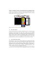
KARI is based on LEON3FT-RTAX and various ASIC/FPGA cores. Fig. 1 shows the
internal architecture of the SCU-DM.
Fig. 1. The SCU-DM internal architecture
3.1
Architecture of LAYSIM-leon3
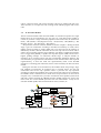
LAYSIM-leon3 has been developed by using the GNU compiler and the GTK library
for GUI, so it can be executed at Windows and Linux platform without any
modification. LAYSIM-leon3 can be divided into seven parts broadly. First the file
loader module is responsible for loading a LEON3 program into memory, and it
analyzes and stores the symbol information and debugging information according to
file format (a.out, elf, or binary format). The source/disassembler module displays the
mixed format of source codes and disassembled code to GUI source viewer. The IU
(Integer Unit) execution module is the core of LAYSIM-leon3 which executes
SPARC v8 instructions. The FPU execution module takes the responsibility of FPU
operation. All GRLIB operations are controlled and executed by GRLIB execution
module. Trap or interrupts are treated by the trap/interrupt handling module. Finally
the GUI control module takes care of the watch/breakpoint operation, real-time
register update, user control of GUI environment.
Fig. 2. LAYSIM-leon3 Emulator Architecture
3.2
File Loader Module
LEON3 programs which can be loaded to LAYSIM-leon3 are a.out file format from
VxWorks 5.4 output and elf file format from VxWorks 6.5, RCC (RTEMS
LEON/ERC32 Cross-Compiler) and BCC (Bare-C Cross-Compiler System for
LEON). Also binary file format can be loaded to LAYSIM-leon3 with address option.
During loading a LEON3 program, the appropriate loader is executed after the
analysis of file format, it extracts symbol and debugging information and copies
text/data segments to memory. If a RAM based LEON3 program is selected, then
stack/frame pointers of the IU are automatically are set for its execution in RAM.
3.3
Source/Disassembler Module
If the matching C source code of a LEON3 program which is loaded through the file
loader module is available, then the source/disassembler module displays the mixed
format to GUI source viewer, otherwise it displays assembler code only. As for
disassemble, the rule of “Suggested Assembly Language Syntax” [4] from SPARC is
adopted for the convenience of software engineers. The LEON3-FT, SPARC v8 core,
supports 5 type’s instructions such as load/store, arithmetic/logical/shift, control
transfer, read/write control register and FP/CP instructions.
To trace the code execution, LAYSIM-leon3 has the function of code coverage. In
GUI source viewer, the executed code line is highlighted with blue color, untouched
code is colored in black, and current executing code line is marked with red color.
After execution, it can report the code coverage of the LEON3 program with source
code.
3.4
IU Execution Module
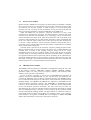
The IU execution module which executes SPARC v8 instructions operates as a single
thread, and it can be controlled by run, stop, step, etc., from GUI control toolbar or
console. It performs 7-stage instruction pipeline of the LEON3-FT; FE (Instruction
Fetch) – DE (Decode) – RA (Register Access) – EX (Execute) – ME (Memory) – RA
(Register Access) – XC (Exception) – WR (Write).
All operations of the IU execution module are shown in Figure 3. During the fetch
stage, it gets two instructions according to PC/nPC from memory or icache, and it
updates icache according to icache update rule. If it cannot access the memory as
indicated by PC/nPC, then the instruction access error trap will be occurred. After it
checks current pending interrupts and conditions (trap.PSR is enabled and interrupt
level is bigger than pil.PSR), it updates the trap base register (TBR) and services a
highest pending interrupt. On instruction decode stage, it analyzes SPARC v8
instruction to be executed, and it calls the corresponding emulation function. The
execute/memory step performs the called function to be executed and it reads required
register/memory, it stores the result into register/memory back. If the decoded
instruction is a floating-point instruction, then it will be treated by the FPU execution
module.
During the execution of each instruction, this module checks the privilege, align,
trap condition of instruction. If exception case is occurred, then it sets the trap
environment and services trap operation where it processes the trap operation
according to LEON3 trap handling rule. If the occurred trap cannot be recovered then
the LEON3 mode is transited to error mode and it stops execution. On non-critical
exception case, it calculates the cycle time of instruction and it updates system clock
and timer registers through the GRLIB execution module which also services the
timed event for various GRLIB operation and user FPGA/ASICs. Lastly the IU
execution module updates GUI environments for timers, UARTs, etc.
Fig. 3. LAYSIM-leon3 IU Execution Module Flow
3.5
FPU Execution Module
Because the FPU, GRFPU-lite of LEON3-FT, follows IEEE-754 standard, LAYSIMleon3 uses the resources of x86 machine to perform FPU instruction and the results
are reflected into the FPU registers. If FPU exception is occurred during FPU
operation, the FPU exception of host x86 machine is first processed accurately and
then the exception information is applied to FSR/FPU of LAYSIM-leon3.
While the GRFPU-lite can perform a single FP instruction at a time, if FP
instructions are performed in succession, first FP instruction is stored in FP queue
until the end of execution and qne.FSR is set to 1(not empty). The IU execution also
will be blocked till the empty of FP queue which means the end of execution of FP
instruction. The calculation of cycle time of FPU instruction is more complicated than
the IU case. And if the register which is the result of previous execution of instruction
is used as a source operand in current instruction, hardware interlock adds one or
more delay cycles. Currently H/W interlock mechanism is implemented in LAYSIMleon3 with the actual LEON3-FT.
The FPU mode is operated as the execution, exception, pending exception mode.
During execution mode, if exceptions such as divide by zero, overflow/underflow are
occurred, then it transits to the pending exception mode, but the IU cannot
immediately aware of the error condition of FPU. The IU finally figures out the FPU
exception mode on executing another FP instruction, then FPU mode is changed to
the exception mode, the FPU exception trap will be invoked by the IU (deferred trap).
If software handles the FPU exception properly, then FP queue becomes empty and
FPU mode is changed to execution mode which operates FP instruction, otherwise the
LEON3-FT enters error mode which halts anymore operation.
3.6
GRLIB Execution Module
The GRLIB execution module in LAYSIM-leon3 implemented various IP cores such
as the memory controller, APBUART, GPTimer, IRQMP, GRGPIO, GRFIFO,
SpaceWire (SpW), etc. They consist of registers, memory, and controller where
software can be accessed as real hardware.
In case of memory controller, it sets the size of RAM/ROM and waitstates. If
software accesses an unimplemented area, the trap will arise, and waitstates will
consume the additional cycles of memory read/write operation. The IRQMP controls
the 15 internal/external interrupts for CPU and it will be treated by the trap/interrupt
handling module. The GRGPIO and GRFIFO are supported in LAYSIM-leon3 for
external interface and DMA operation. The APBUART is implemented as GUI
console or can be redirected to external interface. 3 GPTimers are also implemented
as the real hardware operation mechanism. The scaler and count of timers are
decremented as the cycle time of IU/FPU instruction execution, and if timer is expired,
then corresponding interrupt is invoked, it will be treated by the IU execution module
with the trap/interrupt handling module. The SpW module can send/receive data via
virtual SpW channel to/from external SpW test equipment which is also softwarebased simulator. All registers of GRLIB devices are mapped to AMBA APB/AHB
address and controlled by event function and register operations.
3.7
Trap/Interrupt Handling Module
The LEON3-FT has 3 operation modes: reset, run, error mode. It supports three types
of traps: synchronous, floating-point, and asynchronous traps. Synchronous traps are
caused by hardware responding to a particular instruction or by the Ticc instruction
and they occur during the instruction that caused them. Floating-point traps caused by
FP instruction occur before that instruction is completed. Asynchronous trap
(interrupt) occurs when an external event interrupts the processor such as timers,
UART, and various controllers.
The software handlers for window overflow/underflow trap among synchronous
traps are provided by RTOS or compiler, so they can be handled correctly by software.
But other traps whose handlers are not installed properly by software will lead the
LEON3-FT to error mode. Interrupts can be processed by the IU on no pending
synchronous trap. All trap operations are handled by the trap/interrupt handling
module as the real LEON3-FT trap operation.
4
Software Development/Test on LAYSIM-leon3
The Flight Software based on VxWorks 5.4/6.5 or RTEMS can be loaded and
executed on LAYSIM-leon3 without any modification as the real hardware
environment. For s/w development on the SCU-DM, LAYSIM-leon3 supports the full
system simulator for the SCU-DM which has the Ethernet (LAN91C), VME, IPN,
1553B, RTC, IMSL controllers. All devices are integrated to memory mapped I/O
area in LAYSIM-leon3 and controlled by event function and register operations with
the same operation mechanism of GRLIB devices.
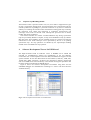
Figure 4 shows the software development environment using BCC and the
embedded debugger of LAYSIM-leon3 can debug as C source code level and trace
variables/memory.
Fig. 4. S/W Development Environment on LAYSIM-leon3
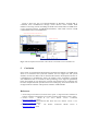
Figure 5 shows the case of VxWorks/Tornado on Windows. Tornado IDE is
connected with LAYSIM-leon3 through virtual network which enables FSW
members to develop, monitor and debug the FSW with Tornado IDE. LAYSIM-leon3
is also connected with the 1553B Monitor/Simulator, which sends /receives 1553B
command/data to/from LAYSIM-leon3.
Software Development Environment (Tornado 2.0/VxWorks 5.4)
LAYSIM-leon3 (SCU-DM model)
Virtual LAN91C
Network
virtual 1553B
1553B Monitor/Simulator
Fig. 5. S/W Development Environment with VxWorks 5.4/Tornado 2.0 on LAYSIM-leon3
5
Conclusion
In this paper we introduced the development of LEON3-FT emulator, LAYSIM-leon3,
which is a GUI-based and cycle-true emulator and can support the full system
simulator for the SCU-DM. And we described the software development and test on
LAYSIM-leon3. LAYSIM-leon3 shows the slightly lower performance compared
with TSIM-leon3 due to overhead of GUI processing, but it supports significantly
better environment for s/w developers. Currently the instruction level verification test
has been completed and the operation level test is undergoing. It will be the main core
of flight software simulator and operation simulator of SWT/KARI.
References
1. Alastari Pidgeon, Paul Robison, Sean McCellan,: QERx : A High Performance Emulator for
Software Validation and Simulations. Proceeding of DASIA 2009, Istanbul, Turkey (2009)
2. Aeroflex Gaisler : GRLIB IP Core User’s Manual. Version 1.1.0-B4104,
http://www.gaisler.com (2010)
3. Aeroflex Gaisler : LEON3FT-RTAX Data Sheet and User’s Manual. Version 1.1.0.9,
http://www.gaisler.com (2010)
4. SPARC International Inc : The SPARC Architecture Manual Version 8,
http://www.sparc.org (1992)