1
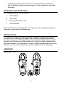
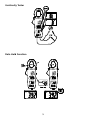
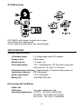
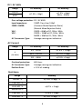
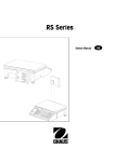
ACD-4
Mini-Clamp DMM, 400A
Users Manual
•
•
•
•
Mode d’emploi
Bedienungshandbuch
Manual d’Uso
Manual de uso
ACD-4
Users Manual
©2009 Amprobe Test Tools.
All rights reserved. Printed in China
English
Mini-Clamp DMM, 400A
Limited Warranty and Limitation of Liability
Your Amprobe product will be free from defects in material and workmanship for 1 year from the
date of purchase. This warranty does not cover fuses, disposable batteries or damage from accident,
neglect, misuse, alteration, contamination, or abnormal conditions of operation or handling. Resellers
are not authorized to extend any other warranty on Amprobe’s behalf. To obtain service during the
warranty period, return the product with proof of purchase to an authorized Amprobe Test Tools
Service Center or to an Amprobe dealer or distributor. See Repair Section for details. THIS WARRANTY
IS YOUR ONLY REMEDY. ALL OTHER WARRANTIES - WHETHER EXPRESS, IMPLIED OR STAUTORY INCLUDING IMPLIED WARRANTIES OF FITNESS FOR A PARTICULAR PURPOSE OR MERCHANTABILITY,
ARE HEREBY DISCLAIMED. MANUFACTURER SHALL NOT BE LIABLE FOR ANY SPECIAL, INDIRECT,
INCIDENTAL OR CONSEQUENTIAL DAMAGES OR LOSSES, ARISING FROM ANY CAUSE OR THEORY.
Since some states or countries do not allow the exclusion or limitation of an implied warranty or of
incidental or consequential damages, this limitation of liability may not apply to you.
Repair
All test tools returned for warranty or non-warranty repair or for calibration should be accompanied
by the following: your name, company’s name, address, telephone number, and proof of purchase.
Additionally, please include a brief description of the problem or the service requested and include
the test leads with the meter. Non-warranty repair or replacement charges should be remitted in the
form of a check, a money order, credit card with expiration date, or a purchase order made payable to
Amprobe® Test Tools.
In-Warranty Repairs and Replacement – All Countries
Please read the warranty statement and check your battery before requesting repair. During the
warranty period any defective test tool can be returned to your Amprobe® Test Tools distributor
for an exchange for the same or like product. Please check the “Where to Buy” section on www.
amprobe.com for a list of distributors near you. Additionally, in the United States and Canada InWarranty repair and replacement units can also be sent to a Amprobe® Test Tools Service Center
(see next page for address).
Non-Warranty Repairs and Replacement – US and Canada
Non-warranty repairs in the United States and Canada should be sent to a Amprobe® Test Tools
Service Center. Call Amprobe® Test Tools or inquire at your point of purchase for current repair
and replacement rates.
In USA In Canada
Amprobe Test Tools Amprobe Test Tools
Everett, WA 98203 Mississauga, ON L4Z 1X9
Tel: 888-993-5853
Tel: 905-890-7600
Fax: 425-446-6390 Fax: 905-890-6866
Non-Warranty Repairs and Replacement – Europe
European non-warranty units can be replaced by your Amprobe® Test Tools distributor for a
nominal charge. Please check the “Where to Buy” section on www.amprobe.com for a list of
distributors near you.
Amprobe® Test Tools Europe
In den Engematten 14
79286 Glottertal, Germany
tel: +49 (0) 7684 8009 - 0
*(Correspondence only – no repair or replacement available from this address. European
customers please contact your distributor.)
ACD-4 Mini-Clam DMM, 400A
1
2
3
4
5
6
7
8
1 Current Jaws
2 Jaw Opening Lever
3 Hold function key
5 Selector switch
4 Push-button for Vac/ Vdc
or Resistance/Continuity
measurement
7 Common (Ground reference)
input jack
6 LCD Display
8 Input jack (+) for voltage and
resistance function
ACD-4 Mini-Clam DMM, 400A
CONTENTS
SYMBOLS................................................................................................................2
UNPACKING AND INSPECTION .............................................................................3
INTRODUCTION......................................................................................................3
OPERATION.............................................................................................................3
SPECIFICATION ......................................................................................................6
MAINTENANCE.......................................................................................................9
TROUBLE SHOOTING..............................................................................................10
Battery Replacement.........................................................................................10
1
SYMBOLS
X
Warning! Dangerous Voltage (Risk of electric shock).
�
Caution ! Refer to the user’s manual before using this Meter.
T
Double Insulation or Reinforced insulation
B
Alternating Current (AC).
F
Direct Current (DC).
N
Low battery indicator
J
Ground (maximum permitted voltage between terminal and
ground).
�
Please remove all the test leads before preforming maintenance,
cleaning, battery replacement, fuse replacement, etc
�
Complies with European Directives
�
Conforms to relevant Australian standards
=
Do not dispose of this pruduct as unsorted municipal waste.
Contact a qualified recycler for disposal
�Warnings!
To ensure safe operation and service of the Meter, follow these instructions.
Failure to observe warnings can result in severe injury or death.
• Do not operate this meter in explosive gas (material), combustible gas
(material) steam or filled with dust.
• When using test leads or probes, keep your fingers behind the finger
guards.
• Remove test lead from Meter before opening the battery door or Meter
case.
• Avoid working alone so assistance can be rendered.
• Do not use test leads or the Clamp Meter if they look damaged.
• Do not use the Meter if the Clamp Meter is not operating properly or if
it is wet.
• Use the Clamp Meter only as specified in the Instruction card or the
protection by the Clamp Meter might be impaired.
2
• Individual protective device must be used if hazardous live parts in
the installation where the measurement is to be carried out could be
accessible.
Unpacking and Inspection
Your shipping carton should include:
1
ACD-4 Meter
2
Test Leads
2
Battery (SIZE AAA, 1.5V)
1
User’s Manual
If any of the items are damaged or missing, return the complete package to
the place of purchase for an exchange.
INTRODUCTION
This meter ACD-4 can be used to measure voltage, resistance and current; It
is an electronic measuring instrument that combines several measurement
functions in one unit. ACD-4 multimeter is portable hand-held devices useful
for basic fault finding and field service work. It can be used to troubleshoot
electrical problems in a wide array of industrial and household devices such as
batteries, motor controls, appliances, power supplies and wiring systems.
Operation
Power On / Off
3
Auto Power Off
The meter will automatically shut itself off after approximately 10 minutes
after power on.
AC V / DC V Measuring
Resistance Measuring
4
Continuity Tester
Data Hold Function
5
ACA Measuring
CAT III 600V with respect to earth for the jaw.
Tactile Barrier for hang guard.
Do not hold the meter across the Tactile Barrier.
SPECIFICATIONS
General Specifications
LCD display digits: 3 1/2 digit large scale LCD readout.
Display count: 2000 counts.
Measuring rate: 1.5 times / sec.
Overrange display:
“OL” is displayed for “e” functions,shows the
real value for “A” and “V” function.
Automatic power off time: Approximately 10 minutes after power on.
Low battery indicator: N is displayed.
Power requirement: 1.5V x 2 batteries
Battery life: ALKALINE 200 hours
Environmental Conditions
Indoor Use.
Calibration:
Operating temperature:
One year calibration cycle.
0°C/32°F ~ 30°C/86°F (≦80% RH)
30°C/86°F ~ 40°C/104°F (≦75% RH)
40°C/104°F ~ 50°C/122°F (≦45%RH)
6
Storage temperature: Overvoltage category:
CAT
-20 to +60°C (-4°F to 140°F), 0 to 80% RH
(batteries not fitted).
IEC 61010-1 600V CAT.Ⅲ.
Application field
Ⅰ
The circuits are not connected to mains.
Ⅱ
The circuits are directly connected to Low-voltage installation.
Ⅲ
The building installation.
Ⅳ
The source of the Low-voltage
installation.
Operating altitude: Conductor Size: Pollution degree: EMC: Shock vibration:
2000m (6562 ft)
27mm (1.06 in) diameter.
2
EN 61326-1
Sinusoidal vibration per MIL-T-28800E
(5 ~ 55 Hz, 3g/0.007lb maximum).
Drop Protection: Dimensions (W x H x D):
Weight: Accessories: 4 feet drop to hardwood on concrete floor.
56mm x 188mm x 28mm
(2.2 in x 7.4 in x 1.1 in)
225g (0.5 lb) including battery.
Battery (installed), Carrying case, Test lead
and User manual.
Electrical Specifications
Accuracy is ±(% reading + number of digits) at 23°C ± 5°C (73.4°F ± 41°F) < 80%
RH.
Temperature coefficient: Add 0.2 x (Specified accuracy) / °C,
< 18°C (64.4°F), > 28°C (82.4°F).
7
DC / AC Volts
Range
200.0V
600V
DC Accuracy
AC Accuracy
±(1.0% + 2dgt)
±(1.5% + 5dgt)
50Hz ~ 500Hz
Over voltage protection: DC / AC 600V
Input Impedance:
10Me // less than 100pF.
CMRR / NMRR:
(Common Mode Rejection Ratio)
(Normal Mode Rejection Ratio)
VAC: CMRR > 60dB at DC, 50Hz / 60Hz
VDC: CMRR > 100dB at DC, 50Hz / 60Hz
NMRR > 50dB at DC, 50Hz / 60Hz
AC Conversion Type:
Average sensing rms indication.
AC Current
Range
DC Accuracy
AC Accuracy
0.0 ~ 40.0A
±(1.9% + 10 dgt)
A
(50~60Hz)
40.0 ~ 200.0A
±(1.9% + 5 dgt)
201 ~ 400A
±(1.9% + 5 dgt)
Overload protection: AC Conversion Type: Position Error: 600 Arms
Average sensing rms indication.
±1.5% of reading.
Resistance
Range
Accuracy
200.0e *3
±(1.0% + 5 dgt) *2
2.000 Ke *3
20.00 Ke *3
±(0.7% + 2 dgt)
200.00 Ke *3
2.000 Ke *3
±(1.0% + 2 dgt)
20.00 Ke *3
±(1.9% + 5 dgt) *1
8
Overload protection: 600V rms
Open circuit Voltage: -1.3V approx.
* 1 < 100 dgt rolling.
* 2 < 10 dgt rolling.
* 3 The maximum LCD reading is 1400 counts.
Continuity
Internal beeper activates if the resistance of the circuit under test is less than
20e. It will then turn off if the resistance is increased beyond 50e. Response
time is approximately 50m sec.
Overload protection: 600V rms.
� - EMC: EN61326-1.
This product complies with requirements of the following European
Community Directives: 89/ 336/ EEC (Electromagnetic Compatibility) and 73/ 23/
EEC (Low Voltage) as amended by 93/ 68/ EEC (CE Marking). However, electrical
noise or intense electromagnetic fields in the vicinity of the equipment may
disturb the measurement circuit. Measuring instruments will also respond to
unwanted signals that may be present within the measurement circuit. Users
should exercise care and take appropriate precautions to avoid misleading
results when making measurements in the presence of electronic interference.
MAINTENACE
If there appears to be a malfunction during the operation of the meter, the
following steps should be performed in order to isolate the cause of the
problem.
1. Check the battery. Replace the battery immediately when the “N”
symbol appears on the LCD.
2. Review the operating instructions for possible mistakes in operating procedure.
Except for the replacement of the battery, repair of the meter should be
performed only by a Factory Authorized Service Center or by other qualified
instrument service personnel. The front panel and case can be cleaned with
a mild solution of detergent and water. Apply sparingly with a soft cloth and
allow to dry completely before using. Do not use aromatic hydrocarbons or
chlorinated solvents for cleaning. If the meter is not to be used for periods of
longer than 60 days, remove the batteries and store them separately
Do not attempt to repair this Meter. It contains no user-serviceable parts.
Repair or servicing should only be performed by qualified personnel.
9
TROUBLE SHOOTING
If the instrument fails to operate, check batteries and test leads etc., and
replace as necessary. Double check operating procedure as described in this
user’s manual.
If the instrument voltage-resistance input terminal has subjected to high
voltage transient (caused by lightning or switching surge to the system) by
accident or abnormal conditions of operation, the series fusible resistors will
be blown off (become high impedance) like fuses to protect the user and the
instrument. Most measuring functions through this terminal will then be open
circuit. The series fusible resistors and the spark gaps should then be replaced
by qualified technician. Refer to the LIMITED WARRANTY section for obtaining
warranty or repairing service.
Battery Replacement
Refer to the following figure to replace the batteries:
10