1
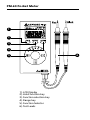
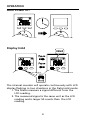
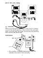
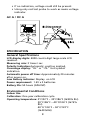
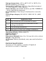
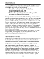
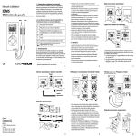
PM-60
Pocket Meter
Users Manual
• Mode d’emploi
• Bedienungshandbuch
• Manual d’Uso
• Manual de uso
Pocket Meter
Users Manual
©2009 Amprobe Test Tools.
All rights reserved. Printed in China
English
PM-60
Limited Warranty and Limitation of Liability
Your Amprobe product will be free from defects in material
and workmanship for 1 year from the date of purchase. This
warranty does not cover fuses, disposable batteries or damage
from accident, neglect, misuse, alteration, contamination, or
abnormal conditions of operation or handling. Resellers are not
authorized to extend any other warranty on Amprobe’s behalf.
To obtain service during the warranty period, return the product
with proof of purchase to an authorized Amprobe Test Tools
Service Center or to an Amprobe dealer or distributor. See Repair
Section for details. THIS WARRANTY IS YOUR ONLY REMEDY.
ALL OTHER WARRANTIES - WHETHER EXPRESS, IMPLIED OR
STAUTORY - INCLUDING IMPLIED WARRANTIES OF FITNESS FOR
A PARTICULAR PURPOSE OR MERCHANTABILITY, ARE HEREBY
DISCLAIMED. MANUFACTURER SHALL NOT BE LIABLE FOR ANY
SPECIAL, INDIRECT, INCIDENTAL OR CONSEQUENTIAL DAMAGES
OR LOSSES, ARISING FROM ANY CAUSE OR THEORY. Since some
states or countries do not allow the exclusion or limitation of an
implied warranty or of incidental or consequential damages, this
limitation of liability may not apply to you.
Repair
All test tools returned for warranty or non-warranty repair or
for calibration should be accompanied by the following: your
name, company’s name, address, telephone number, and proof of
purchase. Additionally, please include a brief description of the
problem or the service requested and include the test leads with
the meter. Non-warranty repair or replacement charges should be
remitted in the form of a check, a money order, credit card with
expiration date, or a purchase order made payable to Amprobe®
Test Tools.
In-Warranty Repairs and Replacement – All Countries
Please read the warranty statement and check your battery before
requesting repair. During the warranty period any defective test
tool can be returned to your Amprobe® Test Tools distributor
for an exchange for the same or like product. Please check the
“Where to Buy” section on www.amprobe.com for a list of
distributors near you. Additionally, in the United States and
Canada In-Warranty repair and replacement units can also be
sent to a Amprobe® Test Tools Service Center (see next page for
address).
Non-Warranty Repairs and Replacement – US and Canada
Non-warranty repairs in the United States and Canada should be
sent to a Amprobe® Test Tools Service Center. Call Amprobe® Test
Tools or inquire at your point of purchase for current repair and
replacement rates.
In USA
In Canada
Amprobe Test ToolsAmprobe Test Tools
Everett, WA 98203 Mississauga, ON L4Z 1X9
Tel: 888-993-5853 Tel: 905-890-7600
Fax: 425-446-6390 Fax: 905-890-6866
Non-Warranty Repairs and Replacement – Europe
European non-warranty units can be replaced by your Amprobe®
Test Tools distributor for a nominal charge. Please check the
“Where to Buy” section on www.amprobe.com for a list of
distributors near you.
Amprobe® Test Tools Europe
In den Engematten 14
79286 Glottertal, Germany
tel: +49 (0) 7684 8009 - 0
*(Correspondence only – no repair or replacement available from
this address. European customers please contact your distributor.)
PM-60 Pocket Meter
1
2
3
4
6
5
1). LCD Display
2). Hold function key
3). Function selection key
4). Range key
5). Function Selector
6). Test Leads
CONTENTS
SYMBOLS........................................................................... 2
UNPACKING AND INSPECTION......................................... 3
INTRODUCTION................................................................. 3
OPERATION........................................................................ 4
SPECIFICATION ................................................................. 8
MAINTENACE..................................................................... 13
TROUBLE SHOOTING......................................................... 13
Battery Replacement.................................................... 14
1
SYMBOLS
X
Warning! Dangerous Voltage (Risk of electric
shock).
�
Caution ! Refer to the user’s manual before
using this Meter.
T
Double Insulation or Reinforced insulation
B
Alternating Current (AC).
F
Direct Current (DC).
N
Low battery indicator
J
Ground (maximum permitted voltage
between terminal and ground).
�
Please remove all the test leads before
preforming maintenance, cleaning, battery
replacement, fuse replacement, etc
�
Complies with European Directives
�
Conforms to relevant Australian standards
=
Do not dispose of this pruduct as unsorted
municipal waste.
Contact a qualified recycler for disposal
W Warning!
To ensure safe operation and service of the Meter, follow
these instructions.
Failure to observe warnings can result in severe injury or
death.
• Do not operate this meter in explosive gas
(material), combustible gas (material) steam or
filled with dust.
• When using test leads or probes, keep your fingers
behind the finger guards.
2
• Use the Meter only as specified in this manual or
the protection by the Meter might be impaired.
• Always use proper terminals, switch position and
range for measurements.
• Do not apply more than the rated voltage, as
marked on Meter, between terminals or between
any terminal and earth ground.
• To avoid false readings that can lead to electric
shock and injury, replace battery as soon as low
battery indicator appears.
• Disconnect circuit power and discharge all highvoltage capacitors before testing resistance,
continuity, diodes, or capacitance.
• To reduce the risk of fire or electric shock; do not
expose this product to rain or moisture.
UNPACKING AND INSPECTION
Your shipping carton should include:
1 PM-60 Meter
2 Battery (GPA76P, 1.5V)
1 User’s Manual
If any of the items are damaged or missing, return
the complete package to the place of purchase for an
exchange.
Introduction
This meter PM-60 can be measured voltage, resistance,
frequency, capacitance, diode, current (uA) and
continuity; It is an electronic measuring instrument that
combines several measurement functions in one unit.
PM-60 multimeter is portable hand-held devices useful
for basic fault finding and field service work. It can be
used to troubleshoot electrical problems.
3
OPERATION
Auto Power Off
Display Hold
The internal sounder will operate continuously with LCD
display flashing in two situations in the Data Hold mode:
1. The Meter measure a signal different from the
LCD reading.
2. The measured signal is the same unit as the LCD
reading and is larger 50 counts than the LCD
reading.
4
Auto Range / Manual Range
Selecting Function
5
Resistor / Capacitor / Continuity / Diode
• For better measurement accuracy of small value
capacitance, subtract the residual capacitance of
the Meter and leads from measurement.
• Under diode mode, LCD displays “bad” when
measuring a diode conducted at forward and
reverse bias.
• LCD displays capacitance mode when no
measurement at Auto-sense mode.
• Under Auto-sense mode, do not measure a
broken component, a unknown component, or a
component with mixed electrical characteristic,
such as measuring a resistor and a capacitor in
parallel. The meter may display incorrectly.
6
AC V / DC / Hz / Duty
W CAUTION
When connecting the test leads to the circuit or device,
connect the black lead first, then connect the red lead ;
when removing the test leads, remove the red lead first,
then remove the black lead.
Volt Sense
• The number of dashes displaying on the LCD
indicates the electric field intensity.
7
• If no indication, voltage could still be present.
• Using only red test probe to work as mains voltage
indicator.
AC A / DC A
SPECIFICATION
General Specifications
LCD display digits: 4000 counts digit large scale LCD
readout.
Measuring rate: 3 times / sec.
Polarity Indication:Automatic, positive implied,
Overrange display: “OL” or “-OL” Unit symbol
indication.
Automatic power off time: Approximately 20 minutes
after power on.
Low battery indicator: Display on LCD
Power requirement: 1.5V x 2 batteries.
Battery life: 50 hours (GPA76P)
Environmental Conditions
Indoor Use
Calibration: One year calibration cycle
Operating temperature: 0°C/32°F ~ 30°C/86°F (≦80% RH)
30°C /86°F ~ 40°C/104°F (≦75%
RH)
40°C/ 104°F ~ 50°C/122°F
(≦45%RH)
8
Storage temperature: -20 to +60°C (-4°F to 140°F), 0 to
80% RH (batteries not fitted).
Temperature coefficient: Add 0.2 x (Specified accuracy) /
°C, < 18°C (64.4°F), > 28°C (82.4°F).
Shock vibration: Sinusoidal vibration per MIL-T-28800E (5
~ 55 Hz, 3g/0.007lb maximum).
Drop Protection: 4 feet drop to hardwood on concrete
floor.
Overvoltage category: IEC 61010-1 300V CAT. Ⅲ., 600V
CAT. II.
CAT
Application field
Ⅰ
The circuits are not connected to mains.
Ⅱ
The circuits are directly connected to Lowvoltage installation.
Ⅲ
The building installation.
Ⅳ
The source of the Low-voltage installation.
Operating altitude: 2000m (6562 ft)
Pollution degree: 2
EMC: EN 61326-1
Dimensions (WxHxD): 56 x 12 x 112 mm (2.2 x 0.5 x 4.4 in)
Weight: 115g (0.25 lb)
Accessories: Battery (installed), carry case and Instruction
Card.
Electrical Specifications
Accuracy is ± (% reading + number of digits) at
23°C/73.4°F ± 5°C/41°F < 80% RH.
9
Function
ACV
Ranges
Resolution
Accuracy
400.0mV
0.1mV
± (1.5%+ 5 D)
4.000V
0.001V
40.00V
0.01V
400.0V
0.1V
600V
1V
± (0.9%+ 5 D)
Frequency Response: 50 ~ 500Hz
AC Conversion Type: AC Coupled Average Sensing, RMS
Indication.
Input Impedance: 10Me, <100pF.
Overload protection: 600V rms.
Function
DCV
Ranges
Resolution
Accuracy
400.0mV
0.1mV
± (0.7%+ 5 D)
4.000V
0.001V
40.00V
0.01V
400.0V
0.1V
600V
1V
± (0.6%+ 2 D)
± (0.7%+ 5 D)
Input Impedance: 10Me, <100pF.
Overload protection: 600V rms.
Function
ohm
Ranges
Resolution
Accuracy
400.0
0.1
± (0.9%+ 5 D)
4.000K
0.001K
40.00K
0.01K
400.0K
0.1K
4.000M
0.001M
40.00M*
0.01M
Open Circuit Voltage: 0.4V
* There is a little rolling less than ± 2%
Overload protection: 600V rms.
10
± (0.9%+ 2 D)
± (1.5%+ 5 D)
CONTINUITY CHECK
Continuity Threshold: Approx. <50e
Continuity Indicator: 2.7 KHz Tone Buzzer.
Input Protection: 600V rms..
Function
Cap
Ranges
Resolution
Accuracy
40.00nF
0.01nF
± (5%+ 0.4nF)
400.0nF
0.1nF
4.000µF
0.001µF
40.00µF
0.01µF
400.0µF
0.1µF
± (2.9%+ 5D)
Measuring Time: <30sec. (400.0µF range),
<10sec. (40.0µF range), <3sec. (other
range)
Overload protection: 600V rms.
Function
Hz
Ranges
Resolution
40.00Hz
0.01Hz
400.0Hz
0.1Hz
4.000KHz
0.001KHz
40.00KHz
0.01kHz
Accuracy
± (0.3%+ 5 D)
Sensitivity: > 10Vp-p (40KHz range)
> 1.5Vp-p (other range)
The signal must have positive and negative waveform
of a cycle.
Max. Sensitivity: 600V rms.
Overload protection: 600V rms.
Function
%
Ranges
Resolution
Accuracy
0.1%
± (0.5%+ 10
D)*
0.1 - 99.9%
*: 30% ≦ Duty ≦ 70%,
11
Square Wave (5 Hz ~ 1KHz)
Sensitivity: 1.5Vp-p
Overload protection: 600V rms.
Function
ACA
Ranges
Resolution
400.0µA
0.1µA
4.000mA
0.001mA
Accuracy
± (1.5%+ 5 D)
Frequency Response: 50 ~ 500Hz
AC Conversion Type: AC Coupled Average Sensing, RMS
Indication.
Input Impedance: Approx. 3Ke
Overload protection: 600V rms.
Function
DCA
Ranges
Resolution
400.0µA
0.1µA
4.000mA
0.001mA
Accuracy
± (0.9%+ 5 D)
Input Impedance: Approx. 3Ke
Overload protection: 600V rms.
DIODE TEST
Test Current: Typical. 350µA
Open Circuit Voltage: Max. 1.8V DC
Input Protection: 600V rm.
� - EMC: EN61326-1.
This product complies with requirements of the
following European Community Directives: 89/ 336/ EEC
(Electromagnetic Compatibility) and 73/ 23/ EEC (Low
Voltage) as amended by 93/ 68/ EEC (CE Marking). However,
electrical noise or intense electromagnetic fields in the
vicinity of the equipment may disturb the measurement
circuit. Measuring instruments will also respond to unwanted
signals that may be present within the measurement circuit.
Users should exercise care and take appropriate precautions
to avoid misleading results when making measurements in
the presence of electronic interference.
12
MAINTENACE
If there appears to be a malfunction during the operation of the
meter, the following steps should be performed in order
to isolate the cause of the problem.
1.Check the battery. Replace the battery
immediately when the “N” symbol appears on the LCD.
2.Review the operating instructions for possible
mistakes in operating procedure.
Except for the replacement of the battery, repair of the
meter should be performed only by a Factory Authorized
Service Center or by other qualified instrument service
personnel. The front panel and case can be cleaned with
a mild solution of detergent and water. Apply sparingly
with a soft cloth and allow to dry completely before
using. Do not use aromatic hydrocarbons or chlorinated
solvents for cleaning. If the meter is not to be used for
periods of longer than 60 days, remove the batteries and
store them separately
Do not attempt to repair this Meter. It contains no userserviceable parts. Repair or servicing should only be
performed by qualified personnel.
TROUBLE SHOOTING
If the instrument fails to operate, check batteries and
test leads etc., and replace as necessary. Double check
operating procedure as described in this user’s manual.
If the instrument voltage-resistance input terminal
has subjected to high voltage transient (caused by
lightning or switching surge to the system) by accident
or abnormal conditions of operation, the series fusible
resistors will be blown off (become high impedance)
like fuses to protect the user and the instrument. Most
measuring functions through this terminal will then be
open circuit. The series fusible resistors and the spark
13
gaps should then be replaced by qualified technician. Refer to
the LIMITED WARRANTY section for obtaining warranty
or repairing service.
Battery Replacement
Refer to the following figure to replace the batteries:
14
15