1
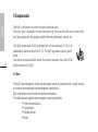
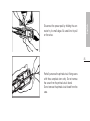
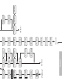
User’s Manual
US v2.0.2
The Vigil is endorsed by:
AAD nv/sa. Advanced Aerospace Designs
Boulevard A. Reyers 193 • B-1030 Brussels • Belgium
✆: +32 (0)2 732 65 52 • F: +32 (0)2 736 06 27
e-mail: [email protected] • website: www.vigil.aero
Vigil USA LLC
1645 Lexington Avenue • DeLand, FL • 32724 USA
✆: +386 736 8464 • F: +386 736 8468
e-mail: [email protected] • website: www.vigil.aero
English
1
User’s Manual
US v2.0.2
Table of Contents
English
1
2
3
2
3.1
3.2
3.3
3.3.1
3.3.2
3.3.3
3.4
3.4.1
3.4.2
3.4.3
3.4.4
3.4.5
3.4.6
3.4.7
3.4.8
Welcome to the World of the Vigil !
Introduction - Your Vigil
Function
Principle
Installation
The Functioning Modes
PRO Mode
STUDENT Mode
TANDEM Mode
Start Up and Shut Down Procedures
Start Up – Display
Starting Up the Vigil
Control Tests
«SETUP» Mode (Parameters)
«INFO» (Information) Mode
«CONFIG» (Configuration) Mode
Display
Shut down
5
6
7
7
8
8
8
8
9
9
9
9
10
12
14
15
16
17
4.1
4.2
4.3
4.4
4.5
5
6
7
8
9
Components
Box
Power Pack
Electronic unit
Cutter
Control unit
Communications Port
Replacing the Power Pack
Replacing the Cutter
Glossary
Road Map
18
18
19
20
20
21
22
24
28
30
English
4
3
English
WARNING
Skydiving is a risky activity
which may cause serious injuries,
the use of Vigil®
will drastically reduce this risk
4
Disclaim
All the commercialised Vigils (100%) passed all our various tests, technical inspections as our
quality control. However, we can’t totally exclude any malfunction on Vigil.
So, A.A.D. nv/sa declines any responsibility in regard to a slightest default occurred to a Vigil,
which escaped detection during test.
1 Welcome to the World of the Vigil !
English
Thank you for your purchase of today’s most sophisticated and modern automatic activation
device. It is a revolutionary safety system that requires no maintenance, can be used for multiple types of skydiving, is extremely durable, and is very user friendly.
We sincerely hope that you will never be in a situation that justifies the use of your Vigil. But,
if this happened to be the case then you have, thanks to the purchase of this Vigil, demonstrated your judicious foresight.
This manual should accompany you on all your commercial airline flights. It contains explanations that will be useful to the airport security staff.
5
The most recent manual is available on the Vigil website at http://www.vigil.aero/manual.
The Vigil is to be used as a last-resort safety device only. It was never intended and is not
be used as a parachute’s primary opening system. The procedures written in this manual
must be followed to ensure that the Vigil functions properly. Incorrect set up or use can
lead to the Vigil functioning improperly. The use of a Vigil AAD does not excuse a parachutist from performing proper emergency procedures. A parachutist should adhere to all
rules and regulations set by his/her country’s skydiving federation.
2 Introduction - Your Vigil
English
6
The Vigil was conceived and developed by a team of engineers and parachutists. Its job is to automatically open the reserve container in the event that you are in freefall at an unsafe altitude.
The compact, aluminum alloy box is exceptionally strong; its ergonomic design fits well into
most current sport rig.
The Vigil can be used for three types of skydiving by the push of just one button. These user
programmable modes are: «Pro», «Student» or «Tandem».
The unit also works as a data recorder. It memorizes the last jump’s freefall time, total time in
freefall, and total number of jumps. This data can be viewed directly from the control unit’s
LCD display or it can be downloaded to a PC through an infrared communications port. A reader and the associated management software are available as an option. (see §5)
The “2 wire” cable technology was developed especially for the
Vigil. It uses Kevlar reinforced cabling that delivers a unique combination of strength and suppleness. The gold plated contacts and
the positive locking system guarantee optimal reliability in all circumstances.
The stainless steel control unit has a 26 x 96 point LCD display
that allows for a very rich dialogue with the parachutist.
The Vigil’s electromagnetic shield protects the Vigil from electromagnetic interferences, like those found in airports and airplanes.
English
It protects efficiently against electromagnetic waves produced by:
• Radio communications
• Transponders
• Mobile phones
• Radar
è A glossary of unfamiliar terms can be found at the end of this manual.
3 Function
7
3.1 Principle
The control unit includes an LCD display, a red LED and a green LED. The function and the altitude correction modes are displayed directly after starting up the Vigil.
Each time the Vigil is turned on it calibrates itself to the current ground elevation. The altitude
correction mode allows you to correct a positive altitude difference between the departure
and arrival ground levels. The Vigil takes this altitude correction into account to calculate the
real activation altitude.
This activation altitude depends on the functioning mode chosen (see § 3.3).
The red LED briefly flashes three times when the Vigil is reaching and passing the activation
altitude.
English
3.2 Installation
The Vigil is completely compatible with most sport rigs on the market today. It can be easily
installed in any harness/container system equipped with a place for an AAD.
All the loops currently available on the market (Spectra CSR style #9512-300, Spectra CSR
style #9512-725, Cypres™ Locking Spectra Cord) are usable.
8
3.3 The Functioning Modes
The Vigil has three functioning modes that can be selected by the user: Pro , Student or
Tandem. The choice can be made while in the «SETUP» mode. (See § 3.4).
3.3.1 Pro Mode
The Vigil releases at 840 Ft. (256 meters) if the freefall speed is equal or superior to 35 m/sec.
(78 mph)*
3.3.2 Student Mode
The Vigil releases at 1040 Ft. (317 meters) if the freefall speed is equal or superior to 20
m/sec. (45 mph)*
English
3.3.3 Tandem Mode
The Vigil releases at 2040 Ft. (622 meters) if the freefall speed is equal or superior to 35
m/sec. (78 mph)*
* The Vigil will activate immediately under the activation height if the freefall speed is equal
or superior to the predetermined speed.
3.4 Start Up and Shut Down Procedures
The Vigil must be turned on at ground level (referance altitude - zero level).
Never turn the Vigil on while in flight.
The procedures listed in this manual eliminate the risk of an undesired start up or shut down.
3.4.1 Start Up – Display
The Vigil’s display is reversible (see § 3.4.6).
In its standard configuration, the Vigil is used with the orange push button situated on the
right of the display. The red LED is positioned in the upper, left corner; it dictates the rhythm
of the start up procedure. The green LED is situated in the bottom, left corner; it confirms the
end of the start up procedure.
3.4.2 Starting Up the Vigil
The Vigil engages and becomes operational after pressing the push button four times.
Those short pressions must be done immediately after the flash of the red LED.
9
English
After the first push the «Hello» message is shown, immediately followed by the «Vigil» message.
Press the push button directly after the flash of the red LED.
Press the push button again directly after the second flash of the red LED.
Press the push button again directly after the third flash of the red LED.
The Vigil then starts its control test sequence.
Start up example:
10
Action
1. Push
2. Push
3. Push
4. Push
Result
«Hello» followed by «Vigil» appears + flash ➯ (2)
Flash ➯ (3)
Flash ➯ (4)
Start of control tests
è Attention: If there is a great change in atmospheric pressure, it is recommended to
shut down and to restart the Vigil to guarantee optimal precision.
3.4.3 Control Tests
The Vigil goes through several control tests of the electronic circuits, the power pack and the
cutter.
If an error is detected the following messages may be shown:
• «Bat Low»
Low reading on the power pack. The Vigil is still operational but
it is imperative to replace the power pack as soon as possible
• «Bat Rpl»
The power pack should be replaced immediately
• «Cut Err»
Malfunction of the cutter
• «Ctl Err»
There is a discrepancy in the electronic circuits
The appearance of one of these messages (with the exception of «Bat Low») puts an end to
the start up procedure and the Vigil will switch itself off.
If the «Bat Low» or «Bat Rpl» messages appears, the user must replace the power pack (see
chapter 6).
If the «Cut Err» message appears, the user must replace the cutter (see chapter 7).
A new cutter is supplied free of charge in exchange for a completed Life Saving Report.
This form is available at http://www.vigil.aero/saving.
These first test procedure is followed by these modes:
«SETUP» (see § 3.4.4), «INFO» (see § 3.4.5), and «CONFIG» (see § 3.4.6)
English
The following messages are shown:
• «Bat OK»
The power pack is functioning properly
• «Cut OK»
The cutter is functioning properly
• «Ctl OK»
The electronic circuits are functioning properly
11
è We recommend to replace the cutter by a certified rigger. The user may not have authorization to replace the power pack or cutter. Some country’s regulations require a certified
rigger to do such replacements. You must adhere to your country’s rules in this situation.
English
If the «Ctl Err» message appears there may be a failure in the electronic circuits. Send the
Vigil back to your distributor for a complete check up. The Vigil is guarenteed to be free from
defects in material and workmanship for 1 year.
12
è In the unlikely event that your Vigil fails to start up, we recommend to contact your rigger who will open the unit and disconnect the power pack. After one minute, reconnect
the power pack, close the box and restart. Once started up, the display will indicate if
there is a problem. If necessary, swap the component in question, check with us at
[email protected], or see your local Vigil dealer.
3.4.4 «SETUP» Mode (Parameters)
At the end of the test sequence it is possible to enter the «SETUP» mode. To do this, press
the push button as soon as the display shows «SETUP» and the red LED flashes.
This mode allows you to correct a positive difference between the departure and arrival
ground levels, and to define the functioning mode (Pro, Student or Tandem - see § 3.3).
To enter an altitude correction press the push button at the same time as «Alt Cor» appears.
The arrow facing up corresponds to an increase of the altitude and the arrow facing down to
a decrease of the altitude. The correction is made in increments of 50 m. (or 150 ft. when the
Vigil is programmed in feet.) Press the push button until the desired positive correction is
achieved.
English
When the required altitude correction is displayed wait for a few moments until the functioning mode «Pro», «Student», or «Tandem» is displayed.
It is possible to modify the functioning mode to «Pro», «Student», or «Tandem» by pressing the push button until the desired mode is achieved. When the required functioning mode
is displayed, wait for a few moments.
The Vigil will then go to the «INFO» (information) mode.
The parameter sequence is described chapter 9, p. 30.
Set up example:
Action
1. Wait
2. Push
3. Push
4. Wait
5. Push
Result
«SETUP» is displayed
Configuration of the altitude correction
Only positive corrections could be implemented
Display of the functioning modes
Select «Pro», «Student», or «Tandem» mode
è The altitude correction will remain in the Vigil’s memory and will be applied on all jumps
that follow.
It is possible to set up the altitude correction from 0 to +2000 meters (0 to +6000 Ft)
è It is stricly forbidden to enter a negative altitude correction under 0 meters or Ft.
13
English
3.4.5 «INFO» (Information) Mode
This mode allows you to display your Vigil’s reference parameters (version and serial number),
data from previous jumps, as well as temperature and atmospheric pressure.
These parameters are as follows (*):
14
Display
Example
Signification
Ver
LCD
#
TJ
TFF
Ver :4.44
LCD :4.44
#44444
TJ :14444
TFF :44h
44m44s
LFF :144s
444 km/h
Software version
LCD version
Electronic unit serial number
Total Jumps (Total number of jumps of the unit)
Total Free Fall (Total free fall duration
in hours, minutes and seconds: hh, mm, ss)
Last Free Fall (Duration and maximum speed of
the last free fall - displayed in seconds and in
km/h or mph)
Number of activations
Temperature in °C or °F depending on
the configuration
LFF
Saves
T
Saves 14
T:+44°C
HPa or Hg
1444hPa
Atmospheric Pressure in hectoPascals or in Hg
English
(*) Certain models can be equipped with custom-built or experimental software.
The information supplied can be different than on standard units.
A specific logo will make these special models visually identifiable.
Once all the information above has been displayed the Vigil will show «CONFIG»; it is then
possible to enter into the configuration mode.
3.4.6 «CONFIG» (Configuration) Mode
To enter into the configuration mode, press the push button as soon as the display indicates
«CONFIG» and the red LED flashes. This configuration mode allows you to choose the type of
measurement units you wish to display, change the display direction, as well as alter the display’s contrast.
Initially, the display indicates «Meters» or «Feet», depending on the existing configuration.
To change the measurement unit, press the push button.
By pressing the push button you can also choose «Metric» or «U.S.».
Press «View» to choose to view the display in its normal configuration or flipped 180°.
The contrast can be adjusted by pressing the push button when «Contrast» is displayed. The
contrast can be adjusted using the up and down arrows.
Once the «CONFIG» mode is finished, the Vigil is operational.
15
Configuration example:
English
16
Action
Result
1. Wait
«CONFIG» displayed
2. Push
Push Choose between «Meters» or «Feet»
3. Push
Push Choose between «Metric» or «U.S.»
4. Push
Push Choose between normal or reversed display
3.4.7 Display
The green LED flashes five times and the «☺ ENJOY» displayed for a few seconds.
If there is no altitude correction, the «Pro, Student or Tandem» mode is displayed.
If an altitude correction was entered, the mode displayed will be, «P, S or T» respectively,
followed by a «+» sign that corresponds to the value of the altitude correction (see § 3.4.4),
the measurement value will be shown in feet (Ft) or meters (m)»
è Check the measurement value (Ft or m) of the altitude correction carefully.
è It is strictly forbidden to move in a vehicle while the Vigil is ON. It is recommended to shut
down the Vigil and to start it again at the drop zone before use.
English
3.4.8 Shut down
The shut down procedure is similar to the start up procedure.
Four quick presses of the push button will shut down the Vigil.
On the first press the «SysOFF» message is displayed.
Press the button a second and third time; do this as soon as the red LED flashes.
Press the button a forth and last time as soon as the red LED flashes. The display will show
«Goodbye» followed by «Vigil» for a few seconds. Finally, green LED flash and the Vigil shuts
down.
Shut down example:
Action
Result
1. Push
Short flash ➯ (2)
2. Push
Short flash ➯ (3)
3. Push
Short flash ➯ (4)
4. Push
«Goodbye» followed by «Vigil» are displayed and the AAD shuts down.
è It is highly recommended to shut down the Vigil (whatever its mode) when the user decides not to jump and to come down by plane.
The Vigil must be switched on again before the next jump.
è The Vigil shuts down automatically 14 hours after its start-up.
17
4 Components
English
The Vigil is delivered in a custom designed aluminum case.
Once your Vigil is installed in its new home (your rig), the case will allow you to safely transport jump accessories like goggles, audible altimeter, altimeters, camera, etc.
18
The Vigil’s power pack (§ 4.2) and electronic unit are encased (§ 4.3) in an
unbreakable, aluminum alloy box (§ 4.1). The Vigil logo makes it easily identifiable.
Two Kevlar reinforced cables ensure the junction between the cutter (§4.4)
and the control unit (§4.5).
4.1 Box
The Vigil’s electromagnetic shield was thoroughly tested to guarantee that it would function
as intended when exposed to electromagnetic interference.
Such interference can be found in airports and airplanes.
The shield protects against electromagnetic waves produced by:
• Radio communications
• Transponders
• Portable phones
• Radar
English
The case is equipped with two positive locking connectors, two integrated bronze filters, and
a stainless steel closing screw.
The bronze filters ensure protection against the intrusion of pollution, such as dust, and provides a certain amount of resistance to water.
The closing screws allow you to open the case very easily if it is necessary to replace the
power pack or the cutter. These operations are described in detail in chapters 6 and 7.
4.2 Power Pack
The power pack is composed of one lithium battery, a “Pulses Plus” element in the lower half
of the case. The battery was developed especially for Vigil by Sonnenschein-Tadiran. It is submerged in epoxy to ensure total water resistance. It does not suffer from memory effect and
is extremely long lasting. The “Pulses Plus” technology supplies the high peak current necessary for the cutter to function.
The power pack works at a temperature range between –25°C and +70°C (-13°F and +158°F).
Additionally, the Vigil’s low consumption components in conjunction with a sophisticated
power-supply management program significantly improves the battery’s life span. The battery’s life span is four years or when the «Bat Low» message appears, whichever comes first.
19
4.3 Electronic unit
English
20
The entirely automated assembly of surface-mounted components (SMD, Surface Mounted
Devices) answers to the strictest standards. The SMD components assembly are associated
with electronic and optical production controls equipments in order to provide a high level of
quality and reliability; such quality approaches military specifications.
The unit also works as a data recorder. It memorizes parameters described in § 3.4.5 and,
notably, the duration of the last freefall jump, the total freefall time, and the total number of
jumps. All these results can be viewed directly from the control unit’s LCD display or it can be
downloaded to a PC using the infrared communications port.
Detailed information is contained in § 3.4.5; information on the communications port is
described in chapter 5.
4.4 Cutter
Designed especially for the Vigil, the cutter severs the reserve loop by mechanically cutting
with a circular blade and melting the loop to ensure its separation.
The cutter is completely confined to avoid any possible damage to the parachute.
If the Vigil is activated, a new cutter will be supplied free of charge upon presentation of a
completed life saving report. This report can also be downloaded from the web site
http://www.vigil.aero/savings
Your rigger can easily replace the cutter. The different operations are described in chapter 7.
English
è Some country’s regulations require a certified rigger to do such replacements. You must
adhere to your country’s rules in this situation.
4.5 Control unit
The control unit is comprised of a reversible display, a red LED that sets the rhythm of the start
up procedure, a yellow LED that confirms the end of the start up procedure and an orange push
button situated, in the standard configuration, on the right of the display. The red LED also
plays the role of infrared transmitter for the communications port (see chapter 5).
The display on the control unit allows for an alphanumerical dialog with the parachutist. (See
chapter 3).
5 Communications Port
The Vigil is equipped with an infrared communications port that allows the user to download
the data recorded during the previous jumps. A reader and the associated management software are available as an option. (See your dealer for price information.)
The parameters of the last 16 minutes of freefall are recorded, as well as the total number of
jumps and other information described in § 3.4.5.
With the help of this communications port and of the associated software, a rigger can also
download a report about tests that were carried out in a decompression chamber.
21
6 Replacing the Power Pack
English
The replacement of the power pack is an easy and fast operation that can easily be performed.
The power pack should be replaced when the following events happens:
• After 4 years of use
• When «Bat Low» or «Bat Rpl» warning messages are displayed by the Vigil
during the start up control tests.
22
è The user may or may not have authorization to replace the power pack. Some country’s
regulations require a certified rigger to do such replacements. You must adhere to your
country’s rules in this situation.
Open the box using the supplied Hex key.
(hexagonal key # 5).
Replacing the power pack does not require
tools.
English
Disconnect the power pack by holding the connector by its small edges. Be careful not to pull
on the wires.
Reconnect the new power pack’s connector and position the power pack to allow the box to
close.
Ensure that the connecting wires of the power pack are correctly positioned and that they will
not hinder the box from closing.
Close the box and tighten the screw with the Hex key # 5.
Switch on the Vigil to ensure that it is functioning correctly (see § 3.4).
23
7 Replacing the Cutter
English
Replacing the cutter after activation is a simple and fast process that can be performed quite
easily.
A new cutter will be supplied free of charge upon presentation of a life saving report.
This report can also be downloaded from the web site http://www.vigil.aero/savings.
24
Open the box using the supplied Hex key.
(hexagonal key # 5).
English
Disconnect the power pack by holding the connector by its small edges. Be careful not to pull
on the wires.
25
Partially unscrew the printed circuit fixing screw
with three complete turns only. Do not remove
the screw from the printed circuit board.
Do not remove the printed circuit board from the
case.
By pushing the two connectors upwards it is
possible to lift the printed circuit slightly.
English
Do not remove the printed circuit from its housing. Any alternation of the hologram-seal glued
between the printed circuit and the top case will
void the warranty.
26
Free the cutter connector and insert the new
cutter.
Check that the connector is correctly positioned
and tighten the printed circuit fixing screw.
English
Reconnect the power pack.
Make sure that the battery’s connecting wires are correctly positioned and they do not hinder
the box from closing.
Close the box and tighten the screw with Hex key # 5.
(*) Do not remove the printed circuit from its housing; doing so will void the warranty.
Warranty
On each Vigil, you will find a quality control number. This number is mentioned on each hologram stuck
on the 4 units composing the Vigil (pyrotechnical cutter, power pack, control unit and electronic unit).
A fifth hologram is placed on the certificate.
This number (hologram) is attributed and placed by the quality control department and plays a primordial role in the warranty of the Vigil.
Electronic unit: any alteration or deterioration stated on the hologram stuck between the printed circuit and the top case will immediately void the warranty!
Power Pack: the hologram covering the fixing screw location of the box will guarantee that the Vigil
has not been openend by user and the warranty is on the whole unit (battery included).
Any replaced element will recieve a new quality control number, chosen by the quality control department.
We guarantee our Vigil for 1 year by replacing the defective parts.
27
8 Glossary
English
Hex (Key)
Electromagnetic shielding
28
Cutter
Infrared (Port)
Kevlar
LCD
Male key for screws with six hollow faces. It is used to
open and to close the box when replacing the cutter or
power pack.
A shield that protects the electronic circuits from electromagnetic waves that may cause the device to malfunction.
A cutting system that simultaneously acts by mechanically cutting and melting the loop inside the reserve container.
Transmitter/receiver of infrared signals that allows an
exchange of data between the Vigil and a PC.
Carbon fiber used to reinforce the cables. It prevents
direct traction on the electrical connections, as well as
protects the junction cables of the control unit and the
cutter.
Liquid Crystal Display. The LCD used to visually convey
SMD
Positive locking
All trademarks mentioned in this manual are the property of their respective owners.
English
LED
information from the control unit to the user. This is the
same type of display as found on today’s mobile phones.
Light Emitting Diode. An LED is used during the start up
and shut down procedures of the device. An LED can
also be found, for example, on a computer keyboard.
Surface Mount Device. It is an electronic component
manufactured to be of reduced size and consumption.
Such technology allows the electronic circuit to be very
reliable and compact.
A mechanical system that locks the connectors in place
to protect them from being accidentally detached.
29
Ctl Err
or
Ctl OK
or
or
Go to (1)
CONFIG
(3)
INFO
(2)
Set-up
or
Cut Err
or
Cut OK
(1)
Bat Low
or
Bat OK
Hello
Set up
9 Road Map
Ver: 4.44
Finished
Bat Rpl
+4444m
Alt Cor
English
30
Français
Go to (3)
Go to (2)
1444 HPa
T: +44°C
Saves 14
30
Finished
244 km/h
LFF: 144s
â Contrast
Goodbye
TFF: 44h
44m 44s
or
Go to (1)
TJ:14444
Student
â+4444m
#44444
U.S.
or
á+4444m
Pro
or
lcd: 4.44
Feet
á Contrast
Contrast
Sys OFF
or
or
or
Sys OFF
View
Metric
Meters
Sys OFF
Info after jump
P+4444Ft
☺ ENJOY
or
View
or
Tandem