1
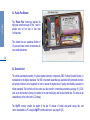
A.A.D. Multimode NATO Stock Number (NSN) 1377-13-121-8660 Vigil®2+ User's Manual US v 2+.0.3 June 2015 Please carefully read and ensure that you fully understand this user’s manual before any use of the Vigil®2+. YOU MUST ALSO READ, FULLY UNDERSTAND AND AGREE TO THE TERMS OF THE DISCLAIMER AND LIMITED WARRANTY PRIOR TO USING THE VIGIL®2+. IF YOU DO NOT FULLY UNDERSTAND AND AGREE TO ALL OF THE TERMS OF THE DISCLAIMER AND LIMITED WARRANTY, YOU MUST NOT USE THE VIGIL®2+. YOU MAY RETURN IT, IN ITS ORIGINAL PACKAGING, FOR A FULL REFUND. YOUR USE OF THE VIGIL®2+ IN THE EQUIPMENT YOU USE FOR MAKING A PARACHUTE JUMP IS CONCLUSIVE PROOF THAT YOU AGREE TO ALL OF THE TERMS OF THE DISCLAIMER AND LIMITED WARRANTY. The Vigil is endorsed by: English AAD NV/SA. - Advanced Aerospace Designs Bld A. Reyers 193 • B-1030 Brussels • Belgium Tel: +32 (0)2 732 65 52 • Fax: +32 (0)2 736 06 27 e-mail: [email protected] • website: www.vigil.aero Vigil America Inc. 1400 Flightline Blvd. Suite C DeLand, FL 32724 USA Tel: +(1)386 736 8464 Fax: +(1)386 736 8468 e-mail: [email protected] Vigil Far East Nam Fong Industrial Building Block 1 227 R/C Avenida Vencelau de Morais Macau Hong Kong: Tel: +(852) 660 30 710 Singapore: Tel: +(65) 8431 8028 [email protected] 1 Table of contents Page Paragraph VIGIL 2+ 1 2 3 3.1 3.2 3.3 3.3.1 3.3.2 3.3.3 2 3.4 3.5 3.5.1 3.5.2 3.5.3 3.5.4 3.5.5 3.5.6 3.5.7 3.5.8 3.5.9 Warning + Disclaimer and limited warranty (see page 37-39) Welcome to the Vigil®2+ World! Introduction Function General Working Principle Installation The Three Activation Modes “PRO” Mode “STUDENT” Mode “TANDEM” Mode Information regarding the Activation Altitude Start Up and Shut Down Procedures Start Up – Display Starting Up the Vigil®2+ Self Tests «SETUP» Menu (Parameters) - Altitude correction Using a positive altitude correction to raise the activation altitude. «INFO» Menu (Information) «CONFIG» Menu (Configuration) Choice confirmation Shut Down 4 5 7 8 8 9 9 9 9 9 10 12 12 13 13 15 16 18 19 20 21 Paragraph 4.1 5 5.1 5.2 5.3 5.4 5.5 5.6 6 7 7.1 7.2 7.3 8 8.1 8.2 8.3 8.4 9 10 11 12 Page Flight Restriction for the Pilot - Airborne Recommendations Vigil®2+ Components Main Box Dual Battery Pack Pulses Plus Element Electronic Unit Cutter Unit Control Unit Waterproof - IP68 Replacement of Parts of the Vigil®2+ Replacing the Battery Pack Replacing the Cutter or Control Unit Service Card Technical Specifications Glossary Dimensions Operating Description Units and conversion factors Communication Port – IR Download Box Service life limit of Vigil®2+ units Disclaimer and limited warranty Road Map / Grafcet (Parameter Sequence Flow Chart) 22 24 24 25 25 26 26 27 28 29 29 29 30 32 34 34 35 35 35 36 37 37 41 English 4 3 wARNING SKYDIVING IS A DANGEROUS ACTIVITY, AND YOU RISK MINOR OR SERIOUS PERMANENT INJURY OR DEATH VIGIL 2+ EACH TIME YOU SKYDIVE. THE CORRECT USE OF THE VIGIL® AAD MAY REDUCE THIS RISK, HOWEVER, THERE ARE SITUATIONS IN WHICH A VIGIL® AAD MAY NOT REDUCE, AND MAY ACTUALLY INCREASE, THE RISK. THE VIGIL® IS A BACKUP DEVICE, WHICH MAY OR MAY NOT SAVE YOUR LIFE, AND IT IS IMPORTANT TO NEVER RELY ON THE VIGIL® AS A LIFESAVING DEVICE. PRIOR TO USING THE VIGIL®, IT IS IMPORTANT TO READ THE VIGIL®2+ USER’S MANUAL VERY CAREFULLY. ALWAYS OBSERVE ALL WARNINGS, AND FOLLOW ALL MANUFACTURER’S INSTRUCTIONS, RECOMMENDATIONS AND SAFETY PROCEDURES. ALWAYS FOLLOW CORRECT OPENING PROCEDURES AND, IF NECESSARY, EMERGENCY PROCEDURES. NEVER SKYDIVE UNLESS YOU ARE FULLY TRAINED AND COMPETENT IN THE USE OF ALL OF YOUR EQUIPMENT, INCLUDING THE VIGIL®. 4 The Vigil®2+ is equipped with an integrated Piezo resistive barometric pressure sensor. Do not expose your Vigil®2+ to pressures above 3000 hPa, (45.5 psi), or to temperatures above 158°F (70°C). The battery pack is designed to operate within a temperature range from -13°F to +158°F (-25°C to +70°C). DISCLAIMER AND LIMITED WARRANTY see pages 37 - 39. You must switch ON your Vigil®2+ ONLY at the take-off zone (reference altitude or ground zero). If you intend to change to a different drop zone, switch OFF your Vigil®2+ before travelling, and switch it back ON at the new drop zone, before take-off. Before each jump it is essential to visually check your LCD screen to ensure its functionality, its activation mode (“PRO”, “STUDENT” or “TANDEM”) and its pre-selected parameters (altitude correction in feet or in meters) are correctly set. NEVER JUMP WITH A BLANK LCD SCREEN ON YOUR Vigil®2+ !! 1. Welcome to the Vigil®2+ World! English We congratulate you on your purchase of today’s most sophisticated and modern, multimode Automatic Activation Device. It is a revolutionary safety device, with no imposed maintenance schedule. The Vigil®2+ will automatically check all of its functional features each time it is switched on. The Vigil®2+ will detect any anomalies by itself. Should an abnormality be found, the controler will display an error message (see page 13 § 3.5.3.), and the Vigil®2+ unit will not switch on. In this case, the Vigil®2+ needs to be analyzed by an authorized dealer, or sent back to the factory for analysis. The Vigil®2+ is designed for a life expectancy of maximum 20 years from the date of manufacture. The above life expectancy is based on the fact that the cutter, the Pulses Plus element and the electronic components have been designed for a functional lifetime of 20 years. The Vigil®2+ is very user friendly. It can be used in your choice of 3 activation modes: “PRO”, “STUDENT” or “TANDEM”. The Vigil®2+, an ALL-IN-ONE Automatic Activation Device (AAD) will also work in U.S. or metric standards units. When traveling on any commercial flight with your Vigil®2+, this manual - as well as the Vigil X-Ray Card should accompany you. It contains explanations that will be useful to the airport security staff. The most recent manual is available on the Vigil website at http://www.vigil.aero/ on the download page. The Vigil®2+ is, in principle, a last resort safety device, which may or may not save your life. It has never been intended to be, and is not to be used as, a parachute’s primary opening system. The procedures written in this manual must be followed to ensure that the Vigil®2+ functions properly. Incorrect setup or use can lead to improper functioning of the Vigil®2+. A skydiver should always adhere to all rules and regulations set by his/her country’s skydiving federation. The use of a Vigil®2+ AAD does not exempt the parachutist from performing proper emergency procedures. ALTHOUGH VIGIL®s HAVE SAVED MANY LIVES, NEVER RELY ON THE VIGIL® TO SAVE YOUR LIFE, IT MAY NOT DO SO IN SOME SITUATIONS. 5 VIGIL 2+ 6 2. Introduction The Vigil®2+ also has a data recorder function (black box). The unit memorizes the last 16 minutes of freefall time (with a maximum of 16 graphs, whichever is reached first), total time in freefall and total number of jumps. This data can be viewed directly from the control unit’s LCD display, or it can be downloaded to a PC through an infrared communication port. The infrared reader and the associated software are available as an option (see page 36 § 9). The “2 wire” technology and the Kevlar reinforced cabling were especially developed for the Vigil®2+ and deliver a unique combination of strength and flexibility. The gold plated contacts and the locking system with a special locking clip on the connectors ensure optimal connection reliability in all circumstances. The control unit: - is equipped with a 26 x 96 dots LCD display which allows interactive and clear communication with the parachutist. - is protected by a special anti-scratch coating and a stainless steel protection cover. The electromagnetic shield protects the Vigil®2+ from electromagnetic interferences, such as those found in airports and airplanes (see page 25 § 5.1). English Your Vigil®2+ was designed and developed by a professional team of engineers and skydivers. Its function is to cut the reserve closing loop in the event that you reach a freefall speed at an unsafe altitude. The flat aluminum alloy box is exceptionally strong; its ergonomic design fits easily into most current rigs. A Vigil®2+ installation kit (pouch, controller window and cutter retainer) can be supplied to rig manufacturers, on demand. The Vigil®2+ can be used for three types of skydiving by pushing just one button. These user programmable modes are: «PRO», «STUDENT» or «TANDEM». 7 3. Function 3.1. General Working Principle: VIGIL 2+ The Vigil®2+ must only be turned on at ground level; it will calibrate itself every 32 sec. progressively to the current ground elevation pressure. This is the “GROUND ZERO” reference. Once your Vigil®2+ is on, at each take-off it will become armed once 1000 ft above “ground zero” reference is reached, if no or a positive altitude correction is applied. When a negative altitude correction is set, the Vigil®2+ will become armed 1000 ft above the preset negative altitude correction, so if the negative altitude correction is over 1000 ft, the Vigil®2+ will become armed maximum 32 sec. after you have reached 90 ft above the “GROUND ZERO” reference (take off location). WHEN A NEGATIVE ALTITUDE CORRECTION IS APPLIED, IT IS MANDATORY THAT THE AIRCRAFT REMAINS AT LEAST 90 ft ABOVE THE GROUND ZERO REFERENCE (take-off zone) FOR AT LEAST 32 SECONDS. THIS ALLOWS VIGIL®2+ TO CHANGE FROM STAND-BY TO FAST MEASURING STATUS. 8 In freefall, the Vigil®2+ starts to continuously calculate the leftover time to reach the activation altitude. When this altitude (or lower) is reached by the jumper at equal or superior speed compared to the factory-set parameters, the cutter of the Vigil®2+ will instantly fire and cut the closing loop of your emergency parachute (<0,002 sec). An “altitude correction” allows you to implement a positive or negative altitude difference between the departure and landing levels (from +6000 ft to -6000 ft or from +2000 m to -2000 m) in steps of 150 ft or 50 m. The Vigil®2+ takes this altitude correction into account to calculate the new activation altitude. This principle also allows you to modify the activation altitude permanently if the airport where you take off and the landing zone are at DIFFERENT altitudes or if there is a hillock near the drop zone. Each mode «PRO», «STUDENT» or «TANDEM» has its own factory-set activation altitude and speed. Choice of mode can be done in the “SETUP” menu (see Page 9 § 3.3). During your aircraft ascent, the Vigil®2+’s red LED will briefly flash three times when it passes through its pre-set activation altitude. The Vigil®2+ will automatically remain ON for 14 hours; it may of course be switched off manually before that time. The selected activation mode «PRO», «STUDENT» or «TANDEM» will remain visible on the LCD display until the Vigil®2+ is switched off or turns off automatically after 14 hours. To avoid an “airborne condition” (See page 23 for more detail) of your Vigil®2+ due to a difference in pressure equivalent to more than plus or minus 90 ft (27,5 m) compared to the “ground zero” reference (pressure), you must ALWAYS manually shut down your Vigil®2+ at the end of the day, and BEFORE leaving the drop-zone. WARNING: IF THE CLOSING LOOP IS NOT ROUTED THROUGH THE CUTTER, THE VIGIL® WILL NOT CUT THE LOOP. 3.3. The Three Activation Modes The Vigil®2+ has three activation modes that can be selected by the user. The choice can be made in the “SETUP” menu (see page 15 § 3.5.4.). Each mode has its own factory settings. The cutter activation data is defined by selecting an activation mode. 9 3.3.1. “PRO” Mode The Vigil®2+ activates when it measures* 1100 ft (335 meters)DFWXDO DOWLWXGH** between IW and IW GHSHQGLQJ RQ ERG\ SRVLWLRQ and below, until 150 ft (46 meters), if the freefall speed is equal or superior to 35 m/sec. (78 mph or 126 km/h) 3.3.2. “STUDENT” Mode The Vigil®2+ activates when it measures* 1300 ft (396 meters) DFWXDO DOWLWXGH** between IW and IWGHSHQGLQJRQ ERG\ SRVLWLRQ and below, until 150 ft. (46 meters), if the freefall speed is equal or superior to 20 m/sec. (45 mph or 72 km/h) 3.3.3. “TANDEM” Mode The Vigil®2+ activates when it measures* 2300 ft (701 meters) DFWXDO DOWLWXGH** between 2040 IW and 2300 IW GHSHQGLQ RQ ERG\ SRVLWLRQ and below, until 150 ft (46 meters), if the freefall speed is equal or superior to 35 m/sec. (78 mph or 126 km/h) * The cutter will activate instantaneously once the pre-determined activation mode parameters (altitude and falling speed) are reached. Please take this information into consideration when determining your main canopy deployment altitudes! Always allow enough time to have a Fully open main canopy approximately 1000 ft (300 meter) above activation altitude! ** If you are in Freefall face to earth, your Vigil® is in the depression zone (burble) and could measure up to ±260 ft ( ±80 meters) higher than your actual altitude (see pages 10 & 11). English 3.2. Installation The Vigil®2+ has been designed to be compatible with most sport harness/container systems on the market today. If a suitable installation kit for an electronic AAD is not yet installed by the rig manufacturer, a Vigil®2+ Installation Kit (pouch, controller window, and cutter retainer) can be supplied and installed in your container by the harness/container manufacturer, or by an authorized rigger. It can be easily sewn into any harness/container system designed for an electronic AAD. All reserve closing loops currently on the market that are similar to Vigil® Dyneema or the Spectra CSR style #9512-300 or the Cypres™ Loop (Spectra Cord) are acceptable for use by the installation of the Vigil®. The Vigil®2+’s cutter must be positioned and rigged as specified by the harness/container manufacturer’s instructions for electronic AAD’s. 3.4. Information regarding the Activation Altitude VIGIL 2+ Please be aware that the Vigil®2+ functions are based on a measured air pressure and on measured time. Those 2 parameters permit the calculation of the exact altitude, in function of the registered air pressure, as well as the vertical speed related to a pressure variation in a certain period of time. For information: The Vigil®2+ is able to register pressure differences of 0,1 hPa which is equivalent to an altitude difference of only ± 2,6 ft (or 0,8 meter)! Important note: The registered pressure by the sensor will vary, according to the body position of the skydiver (face to earth or back to earth) up to 10 hPa (=mbar) which is equivalent to +-260 ft (+-80 m)! 10 Example: Let’s consider two skydivers in free fall, at exactly the same altitude but one is falling back to earth and the second one is falling face to earth. The influence of their falling position on their respective AAD reading is as follows: (I) back to earth (II) Face to earth Depression zone (burble) No influence AAD or pressure sensor located in depression zone (burble) Both at the same altitude Y Pressure sensor location Pressure = X hPa Vigil®2+ will register a pressure of X hPa The stated or real altitude y ft (or m) Pressure = X hPa – 10 hPa Vigil®2+ in depression zone will register an up to 10 hPa lower pressure, notwithstanding they are at the same level The stated altitude Y +(±260 ft) or +(±80 m) Conclusion: Therefore, a compensation of +260 ft or +79 m above the nominal activation altitude has been integrated into the software. For example in "PRO" mode, a programmed activation altitude of 1100 ft or 335 m has been set to ensure that, notwithstanding the skydiver’s body position, activation will always be at a minimum altitude of 840 ft or 256 m (actual altitude) above the ground level. Remarks: • In a test chamber, the activation in "PRO" mode will be at 1100 ft (840 ft + 260 ft) or 335 m (256 m + 79 m) as there is no depression zone (burble). • The Vigil®2+ has an opening accuracy of ±65 ft or ±20 m in all modes thanks to our patented “Permanent Left Over Time Calculation” method. English If the Vigil®2+ is set in "PRO" mode, it will activate at a minimum altitude of 840 ft or 256 m above the ground, at a falling speed of 78 mph or 35 m/sec. or greater. It is well accepted that this minimum activation level must be guaranteed whatever the position of the skydiver. If the skydiver is falling in a back to earth position, the reading will reflect the correct pressure, since the sensor is not influenced by a depression (burble), but if the skydiver is falling face to earth, then the sensor located in the depression zone (burble) will read a pressure up to 10mbar lower, or an altitude ±260 ft or ±79 m above the real altitude, and will, in this case, activate later, or ±260 ft or ±79 m lower, i.e. at an actual altitude of 580 ft or 177 m above the ground level, which would be too low. 11 3.5. Start Up and Shut Down Procedures VIGIL 2+ It is imperative that the Vigil®2+ be switched ON at the ground level of your take-off zone. (This becomes the “GROUND ZERO” reference altitude). Your Vigil®2+ will recalibrate itself for variation in the atmospheric pressure. Attention: If there is a rapid change in atmospheric pressure (more than 10 hPa), it is recommended that you shut down and restart your Vigil®2+ to ensure optimal precision. 3.5.1 Start Up – Display In its standard configuration, the Vigil®2+ is used with the orange push button situated at the right side of the display. The red LED is positioned in the upper corner and indicates the timing of the start up procedure. The green LED is situated in the bottom corner of the controller and confirms the end of the start up procedure. The Vigil®2+‘s display is reversible (see page 19 § 3.5.7.) «view» «view» 12 Never switch on your Vigil®2+ in an aircraft ! In short: Action 1. Push 2. Push 3. Push 4. Push Result «Hello» followed by «Vigil 2+» appears + flash ➯ (2) Flash ➯ (3) Flash ➯ (4) Start of self tests English 3.5.2. Starting Up the Vigil®2+. The Vigil®2+ becomes operational after pressing the orange push button four times. These short presses must be done immediately after each flash of the red LED. After the first push (hold for 1 or 2 seconds) the «Hello» message is shown. If no message appears, please repeat the previous operation. «Hello» is immediately followed by «Vigil 2+» on the LCD. Press the push button immediately after the red LED first flashes. Press the push button immediately after the second flash of the red LED. Press the push button immediately after the third flash of the red LED. The Vigil®2+ will then automatically start its self-test sequence. 13 « VIGIL 2+» « VIGIL 2+» « VIGIL 2+» « BAT OK » The startup and shut down procedures listed in this manual have been established to reduce the risk of an unwanted start up or shut down sequence and to ensure that the Vigil®2+ cannot be turned on or off by accidentally pressing the push button. 3.5.3. Self Tests The Vigil®2+ automatically goes through a complete test sequence each time it is switched on. It verifies that the battery pack, the cutter and the electronic circuits (main functions) are in proper working order. VIGIL 2+ The following messages are shown: The battery pack is functioning properly. • «Bat OK» The cutter resistance is tested O.K. • «Cut OK» The electronic circuits are functioning properly. • «Ctrl OK» If an error is detected the following messages may be shown: • «Bat Low» Low Battery, the Vigil®2+ is still operational, but the dual battery pack must be replaced as soon as possible. * (see page 29 § 7.1) • «Bat Rpl» The dual battery pack must be replaced, the Vigil®2+ will not switch on. * (see page 29 § 7.1) Cutter resistance is out of tolerance, the Vigil®2+ will not switch on. • «Cut Err» A discrepancy in one of the electronic circuits is observed, unit will not switch on. • «Ctrl Err» 14 If one of these messages is displayed (except for «Bat Low»), the startup procedure will end, and the Vigil®2+ will switch itself off. If the «Bat Low» message appears, the battery pack must be replaced as soon as possible (see page 29 § 7.1) If the «Bat Rpl» message appears, the battery pack must be replaced prior to the next jump (see page 29 § 7.1) If the «Cut Err» message appears, the cutter unit must be replaced prior to the next jump (see page 30 § 7.2). A new cutter will be supplied free of charge if a completed “Life Saving Report” is posted and approved (see our website http://www.vigil.aero/ on the download page). We recommend that Vigil®2+ parts be replaced by a certified rigger or by a Vigil® approved expert. The regulations in some countries require a certified rigger to do such replacements. The user may not have authorization to replace the cutter or controller unit. In such situations, you must adhere to your country’s rules. If the «Ctrl Err» message appears due to a failure in the electronic circuits, you must send the Vigil®2+ back to your dealer or to the factory for a complete checkup, before the next jump. DO NOT try to restart the Vigil®2+ again. 3.5.4. «SETUP» Menu (Parameters) Altitude correction. The «SETUP» menu enables you to implement a positive or negative altitude correction (in feet or meters) between the departure and arrival ground levels, as well as select the desired mode («PRO» «STUDENT» «TANDEM») (see example page 17). It is possible to enter the «SETUP» menu at the end of the self testing sequence. To do this, press the push button as soon as the display shows «SETUP» and the red LED flashes. It is possible to implement an altitude correction from +6000 ft to -6000 ft or from +2000 m to -2000 m. To enter or modify a positive or negative altitude correction, press the push button while «Alt Cor» appears. The arrow facing up corresponds to an increase of the altitude value and the arrow facing down to a decrease of the 15 altitude value. The correction is made in increments of 150 ft or 50 m when the Vigil®2+ is set in meters. Press the push button until the desired positive or negative altitude correction is achieved. For example: +100 m for higher landing zone compared to the take-off zone and -100 m. for a lower landing zone. When the required altitude correction is displayed wait for a few moments and the mode selection («PRO» «STUDENT» «TANDEM») will appear on screen. Important note: If you land at a different altitude than your “GROUND ZERO”, please be aware that the original “GROUND ZERO” reference, will remain in the Vigil®2+'s memory and will be applied to all following jumps, as long as your Vigil®2+ has not been switched off. Your Vigil®2+ MUST be reset after you have landed, and prior to your next jump at the other drop zone. By switching your Vigil®2+ off and back on again, the Vigil®2+ will reset itself. Please remember that any implemented “Alt Cor” will remain in the Vigl®2+ memory and will only be cancelled if manualy reconfigured in the “SETUP” menu. English This first test procedure is followed by 3 different menus: «SETUP», «INFO», and «CONFIG» (see page 8 § 3). Recommendation: if the Vigil®2+ is not yet configured to your standard measurement units, go first to the “CONFIG” menu (see page 19 § 3.5.7.) to set the required units (U.S. or metric) before other settings. 3.5.5. Using a positive altitude correction to raise the activation altitude. VIGIL 2+ As stated on page 9 § 3.3, in «PRO» settings a Vigil®2+ activates at a measured altitude of 1100ft (335 meter)(actual altitude of 840-1100 feet, depending on body position). To increase safety margins, an altitude correction can be performed ( see page 15 § 3.5.4. ) Some important points to remember: - Once an altitude correction is applied, this will stay in the Vigil®2+’s memory, until you manually remove it in the «SETUP» menu. - When you raise the activation altitude, always allow enough time to have a fully open main canopy approximately 1000 ft above your new activation altitude. During a slow opening, it may take longer until you have a fully open main canopy, whitch may bring you closer to the activation altitude you choose. - A Vigil®2+ will activate at the measured altitude it is set in. Please read page 9, 10 and 11 carefully to understand this !! - When a positive altitude correction is made, the Vigil®2+ will disarm at 150 ft (46 meter) above the “ground zero reference”, 16 the same altitude as when no altitude correction is applied. This means on a positive altitude correction, you will increase the activation window. The “disarming" altitude of 150 ft above the “ground zero” does NOT increase ! When a negative altitude correction is applied, the Vigil®2+ will disarm 150 ft (46 meter) above the preset negative altitude correction, also known as the "new landing zone". It is each's individual's responsibility to make sure he or she, has a fully open main canopy well above the activation altitude. We recommend allowing approximately 1000 ft between a fully open main canopy and the activation altitude. This should allow enough time to deal with emergency procedures (if necessary) and prevent a possible two-canopy out situation. The possibility to raise the activation altitude, and keep it until manually changed in the “setup” menu, has always been in all Vigil® AAD's produced since 2003. Vigil®2+ in «PRO» settings with positive altitude correction of 100 meters Vigil®2+ in «STUDENT» settings without altitude correction Vigil®2+ in «STUDENT» settings with negative altitude correction of 600 feet Vigil®2+ in «Tandem» settings without altitude correction Vigil®2+ in «Tandem» settings with positive altitude correction of 450 feet English Vigil®2+ in «PRO» settings without altitude correction 17 3.5.6. «INFO» Menu (Information). • This menu allows you to display your Vigil®2+’s reference parameters (version, date of manufacture and serial number), data of previous jumps, as well as temperature and atmospheric pressure. • To enter the «INFO» menu,press the push button as soon as the display shows «INFO» and the red light flashes. VIGIL 2+ These parameters are in clear language in function of the chosen units and as follows (*see page 19 § 3.5.7.): 18 Note: the number 8 is used for illustration (all segments used in a number) #88888 88/88 Software Version Controller version Electronic Unit Serial Number Production week and year (for example 26/06 = week 26 in 2006) Total Jumps (Total number of jumps with this unit) Total Free Fall - Total free fall time with this unit in hours, followed by minutes and seconds Last Free Fall - Duration displayed is seconds and maximum speed of the last freefall displayed in km/h or mph Number of activations on your Vigil®2+ Temperature of Vigil®2+ main unit in °F or °C depending on the configuration Atmospheric Pressure in inches of mercury (inHg) or hectopascal (hPa) As reference: Standard logo English (*) Certain special models may be equipped with custom-built or experimental software. In such cases, a specific identification logo on the cover is used, and a specific manual will be issued. The information supplied for those units could be different from that supplied for the Vigil®2+ units. Xtreme logo 3.5.7. «CONFIG» Menu (Configuration) This configuration menu allows you to choose the type of measurement units you wish to display, reverse the display characters and adjust the contrast of the display. To enter into the configuration menu, press the push button as soon as the display indicates «CONFIG» and the red LED flashes. Initially, the display indicates «Feet» or «Meters», depending on the existing configuration. To change the measurement unit, press the push button. You can choose «U.S.» or «Metric» by pressing the push button (°Fahrenheit, mph, inches of mercury or °Celsius, km/h, hectoPascal). Press «View» to choose to view the display in its normal configuration or flipped 180° «View» The contrast can be adjusted by pressing the push button when «Contrast» is displayed, in accordance with the up and down arrows (it will not fade out). «View» Once the «CONFIG» menu is completed, the Vigil®2+ is operational and will keep in memory the chosen configuration. 19 For example: 4. Push 5. Push Display «CONFIG» displayed Choose between «Feet» or «Meters» Choose between «U.S. » or «Metric» (°Fahrenheit, mph, inches of mercury or °Celsius, km/h, hectoPascal) Choose between normal or reversed display «View» or Contrast or contrast «View» VIGIL 2+ 1. 2. Push 3. All of the parameter sequences are described in the Parameter Sequence Flow Chart. (see page 40 § 12.) 20 3.5.8. Choice confirmation The green LED flashes five times and the message « :-) Enjoy» is displayed for a few seconds to confirm the Vigil®2+ is ready for use. Remark: While the message «:-) Enjoy» is displayed, by pushing the button you can go back to the three menus’ (SETUP, INFO or CONFIG) for a possible verification or modification. If no altitude correction is entered, the chosen “PRO”, “STUDENT” or "TANDEM" mode remains displayed. If an altitude correction was entered, the chosen mode will be displayed as “P” (for PRO), “S” (for STUDENT) or ”T” (for TANDEM), followed by a «+» or «-» sign preceding the value of the implemented altitude correction (see example page 17). The value will be shown in feet (ft) or meters (m). After switch on, the Vigil®2+ stays on for a period of 14 hours, and will then switch off automatically if at “ground zero” reference (see page 23 for more detail). At the next switch-on, Vigil®2+ will retain in its memory, all of the previous settings used with the exception of the ground zero reference. The ground zero reference is reset at each switch on. BEFORE EACH JUMP, check the unit carefully for any implemented mode or altitude correction (in ft. or m). For 2 minutes after each landing, your jump information will be displayed (Last FF time & speed). LCD pixels remain inverted. This same jump information is accessible at any time (displayed for 30 sec.) by pushing the LCD button once. 21 3.5.9. Shut down. (The shut down procedure is similar to the start up procedure). Vigil®2+. A quick press of the push button after each LED flash (4 times) will shut down the On the first press the « SysOFF» message is displayed. Press the button a second and third time; do this as soon as the red LED flashes. Press the button as soon as the red LED flashes a fourth and last time. The display will show «Goodbye» followed by «Vigil2+» for a few seconds. Finally, the green LED flashes very briefly and then the Vigil®2+ shuts down. For Example: Result 1. Push Short flash ➯ (2) « Sys OFF» Short flash ➯ (3) « Sys OFF» Short flash ➯ (4) « Sys OFF» 2. Push 3. Push 4. Push «Goodbye» followed by «Vigil 2+» are displayed before the AAD shuts down. English The Vigil®2+ is now ready for use and is in a stand-by status. While in stand-by status, the unit re-calibrates itself every 32 sec. After take-off the Vigil®2+ will become armed once 1000 ft above “ground zero” reference is reached, if no or a positive altitude correction is implemented. When a negative altitude correction is implemented, the Vigil®2+ will become armed 1000 ft above the preset negative altitude correction (see page 8 § 3.1.) After take-off (max 32 sec. above 90 ft) the Vigil®2+ will go in to fast measuring mode (Airborne status). You can notice this when the LCD pixels invert. (see image on page 28) If the LCD pixels are inverted on the ground and prior to take off, your Vigil®2+ is Airborn and therefore not reading the correct Ground Zero reference. In this case, you must switch off and restart your Vigil®2+, to get the correct Ground Zero reference. 4. Flight restriction for the pilot - Airborne VIGIL 2+ 22 Vigil®2+ will work correctly even when used in a pressurized cabin as long as the pressure differs at least ±3 hPa compared to the atmospheric air pressure at take-off. - Inside this zone, the Vigil®2+ is in stand-by status, measuring every 32 sec. With gradual recalibration to the atmospheric air pressure. Outside this zone, Vigil®2+ will go in fast measuring status, measuring 8 times per sec, with a fixed ground zero reference in a maximum delay of 32 sec. reached if no or a positive altitude correction is implemented. When a negative altitude correction is implemented, the Vigil®2+ will become armed 1000 ft above the preset negative altitude correction, also known as the new landing zone. The Vigil®2+ stays armed until 150 ft above "Ground zero" reference when no or a positive altitude correction is implemented. The Vigil®2+ will not activate below this altitude. When negative altitude correction is implemented, Vigil®2+ will remain armed untill 150 ft above the preset negative altitude correction. The Vigil®2+ will not activate below this altitude. To avoid unexpected firing of the cutter, you must switch OFF your Vigil®2+ before travelling in a closed vehicle (car, bus, train ...) due to possible air pressure variation. However, there is no problem travelling in an open vehicle at the drop zone altitude. Prior to opening the door of an aircraft in flight while it is in the activation zone (below 500 m or 1640 ft.), it should be determined whether or not there are any Vigils on board which are set to Student Mode. Certain aircraft configurations can create a pressure spike which can activate a Vigil®2+ AAD, when it is set to Student Mode and the aircraft is in the activation zone. 23 As long as your Vigil®2+ is not measuring the switch on pressure or its “Ground zero” reference (90 ft / 27,5 m) it will stay airborne, (measuring 8 times/sec.) You must ALWAYS switch off your Vigil®2+ before any move to another location and switch on your Vigil®2+ at the new take-off zone/location to implement the new “ground zero” reference. Be aware that any implemented altitude correction will not affect the original “Ground zero" reference altitude. It will adjust the activation altitude in function of the implemented altitude correction parameters. After such a jump, you need to switch your Vigil®2+ off and back on again to implement the new “Ground zero” reference altitude and manually remove the previous altitude correction. (If no longer required) If decending in an aircraft with an armed Vigil®2+, the pilot must be advised of the status of your Vigil®2+ to limit his descent rate according to the mode less than 20m/sec. (3960 feet per minute) for “STUDENT” and less than 35m/sec. (6864 feet per minute) for “PRO” or “TANDEM” and in the activation zone (this is especially important for Vigil®2+ programmed in “STUDENT” mode). In these circumstances we recommend that the Vigil®2+ be switched off, if possible. English Vigil®2+ is the most accurate AAD on the market. It becomes armed once 1000 ft above “Ground zero” reference is To get the correct GROUND ZERO REFERENCE, you must only switch the Vigil®2+ ON once you arrive at the take-off zone. Afterwards, enter any altitude correction, if needed. VIGIL 2+ When the elevation of your landing zone differs by more than 90 ft (27,5 m) compared to your initial take-off zone and this landing zone becomes your new take-off zone, it is necessary to switch your Vigil®2+ off and back on again so that it can re-calibrate itself. Check the display carefully before each jump to verify that its settings are correct. Manually shut down your Vigil®2+ after the last jump of the day. The Vigil®2+ will shut down automatically 14 hours after its start-up. 24 To avoid undesired Vigil®2+ firings, if you enter a plane with a pressurized cabin, please notify the pilot that he is not allowed to do any pressurization tests to pressures equivalent to the Vigil®2+ activation altitude (below 1640 ft or 500 m in “STUDENT” or “PRO” mode, or below 2300 ft or 701 m in “TANDEM” mode), with a pressure variation equivalent to, or in excess of, a vertical speed greater than 45 mph (20 m/sec). It is impossible to enter a negative altitude correction of more than 1500 ft or 500 m below mean sea level (equivalent to >1090 mbar). In this case the controller will indicate «Invalid» and the Vigil®2+ unit will not switch on. 5. Vigil®2+ Components The Vigil®2+'s Dual Battery Pack (page 25 § 5.2.), the Pulses Plus Element (page 26 § 5.3.) and the Electronic Unit (page 26 § 5.4.) are located in an unbreakable, aluminum alloy Main Box (page 25 § 5.1). Two flexible electric cables, reinforced by 2 Kevlar cords, ensure the junction between the main unit (Main Box) and the Cutter Unit (page 27 § 5.5) as well as between the Main Unit and the Control Unit (page 28 § 5.6). 5.1. Main Box NEVER OPEN THE MAIN BOX OF THE VIGIL®2+!! Opening the main-box of Vigil®2+ voids all warranties !! 5.2. Dual Battery Pack - NATO Stock Number (NSN) 6130-13-119-7106 The battery pack is composed of 2 lithium AA cells in the lower half of the case. It is not subject to any memory effect and is extremely long lasting. The battery pack works at a temperature range from -13°F to +158°F or from -25°C to +70°C. The use of low consumption components in conjunction with a sophisticated power management program has significantly improved the battery’s life span. The battery’s life span is expected to be a minimum of 5 years, or 2000 jumps. When the «Bat Low» or «Bat Rpl» message appears, the battery pack needs to be replaced (see page 29 § 7.1). Regardless of the above-stated life span, the battery pack must be replaced after 10 years of use (max. operational lifetime). English The Vigil®2+ electromagnetic shield was thoroughly tested to ensure that it would function as intended when exposed to electromagnetic interference (up to 100 volt/m). Such interference can be found in airports and aircraft. The special shielding foil protects against electromagnetic interference waves produced by: • Radio communications • Mobile phones • Transponders • Radar Two connectors and three integrated stainless steel filters are fixed in the Main-Box. The stainless steel filter ensures protection against pollution, such as the intrusion of dust, and provides a instant transfer of outside air pressure to the pressure sensor (keep it clean and dry). 25 5.3. Pulses Plus Element VIGIL 2+ The “Pulses Plus” technology supplies the high peak current necessary for the cutter to activate and cut the loop in less than 2 milliseconds. This element has an operational lifetime of 20 years and under normal circomstances will never need replacement. 26 5.4. Electronic Unit The entirely automated assembly of surface-mounted electronic components (SMD, Surface Mounted Devices) is manufactured to the highest standards. The SMD components assemblies are assembled with permanent electronic and optical production control equipment in order to ensure the highest level of quality and reliability, equivalent to military standards. The electronic unit also works as a data recorder. It memorizes parameters (see page 18 § 3.5.6) such as the total number of jumps, the duration of the last freefall jump and the total freefall time. This data can be viewed directly on the control unit’s LCD display. The Vigil®2+ memory contains the graphs of the last 16 minutes of freefall and partial canopy ride, and can be downloaded to a PC using the Vigil®2+ communication port. (see page 36 § 9.) 5.5. Cutter Unit English The Cutter Unit is patented and designed especially for the Vigil®2+ and has a life expectancy of 20 years. The cutter severs the reserve loop using a pyrotechnical cutting action with a circular knife. Due to a high internal temperature, it will also melt the loop to ensure its separation. The cutter is completely enclosed to avoid any possible damage to the parachute. If the Vigil®2+ is activated for a lifesaving event, a new cutter will be supplied free of charge, only upon presentation of a complete Life Saving Report, approved by Vigil®. This document can be downloaded from the Vigil website http://www.vigil.aero/. 27 The cutter is field (rigger) replaceable. (see page 30 § 7.2). Some countries’ regulations require a certified rigger to do such replacements. In this situation you must adhere to your country’s rules. A Dual Cutter can be supplied for reserve containers closed with a dual pin. VIGIL 2+ 5.6. Control Unit. The control unit is composed of a reversible display, a red LED that sets the timing of the start up and shut down procedure, a green LED that confirms the end of the start up procedure and an orange push button situated in the standard configuration, on the right of the display. The 26 x 96 dots display on the control unit allows clear alphanumerical communication with the parachutist; it is protected by a special scratchproof coated screen and a stainless steel cover. The red LED is also used as transmitter for the infrared communications port. (see page 36 § 9). 28 6.Waterproof – IP 68 English 6.1. The Vigil®2+ has been designed to resist water immersion of up to 1.8 meter (6 ft) depth for a maximum of 24 HOURS (IP 68). After such immersion or contact with water, the Vigil®2+ built-in stainless steel filter does not need to be replaced. If the Vigil®2+ has been in contact with salt water, it needs to be rinsed with clear water. After contact with water, the 3 filters need to be dried with a water absorbent cloth, household paper or a cotton swab. Leave the device for 12 hours in an environment with a ambient temperature of +18°C (+65°F) before the installation in a rig. IT IS MANDATORY TO SEND THE VIGIL®2+ BACK TO THE FACTORY FOR AN INSPECTION OF THE UNIT BEFORE THE NEXT JUMP IN THE FOLLOWING CASES: - IF THE VIGIL®2+ HAS BEEN IMMERSED IN SALT OR CLEAR WATER DEEPER THAN 1,8 METER (6 ft). - IF THE VIGIL®2+ HAS BEEN IMMERSED FOR MORE THAN 24 HOURS IN WATER. Do not open your Vigil®2+’s main box case. 7. Replacement of Parts of the Vigil®2+ 7.1. Replacing the Battery Pack. Vigil®2+ Dual Battery Pack, can only be changed by A.A.D nv/sa or Vigil America. Therefore the Vigil®2+ has to be returned for a battery change. For Battery replacement, please contact A.A.D.nv/sa or Vigil America. The battery must be replaced after 10 years of use (operational life). 29 7.2. Replacing the Cutter or Control Unit We highly recommend that replacements of a Cutter or Control Unit from the Vigil®2+ be done VIGIL 2+ by a certified rigger or through a Vigil®2+ dealer. Replacing the Cutter Unit after activation, or the Control Unit if necessary, is a simple and fast process which can be performed quite easily by your rigger or through a Vigil®2+ dealer. Every (dis)assembling operation must be done with the Vigil®2+ switched off. (see page 21 § 3.5.9.) How to be sure the Vigil®2+ is switched off. 30 1. Press on the push button only one single time to display “Hello” on screen. 2. Wait until a blank screen appears again (proves that the unit is switched off). 3. Perform procedure as shown and described on page 31. 4.Perform a new start up procedure for final check. (see page 13 § 3.5.2.) 5. Fill in the Service Card (see pages 32 & 33 § 7.3.) English I. Unscrew Connectors Locking Clip (CLC) II. Remove Connectors Locking Clip (CLC) III. Manually unscrew connector of spare unit (for example cutter) IV. Unplug connector 31 V. Reconnect and manually tighten the new spare unit (Cutter or Control unit) VI. Place Connectors Locking Clip (CLC), and check if CLC locks both connectors VII. After CLC is well positioned, secure with original screw. VIII. Check if CLC is closely attached to Main Box (no space between both objects) It is mandatory to CORRECTLY place the Connectors Locking Clip !! If the CLC is missing, or damaged, or if not correctly positioned, DO NOT JUMP with this Vigil®2+ !! 7.3 Service Card. VIGIL 2+ Every replacement part comes with a Service Card (Vigil® AAD Service Card) with a hologram number and a date of manufacture (DOM) for the cutters, the software version for the control units. Others can be for example a software upgragde.The card is identified with a hologram sticker with a new number. When the replacement of a subpart has been done, it is mandatory to proceed as follows: 1.Fill out the Service Card. 2.Send a copy of the Service Card to A.A.D. nv/sa. by fax +32 2 7360627 or via e-mail to [email protected] 3. Hand it to the owner of the Vigil®. Make sure that the owner keeps the original Service Card with the original Test Certificate card and the documents of the rig. 32 This procedure is important for our After Sales Service, as it allows us to update our files and to guarantee the replacement part with a 2 year warranty. 33 English 8. Technical specifications 8.1. Glossary VIGIL 2+ Electromagnetic shielding: A special metal shield that protects the electronic circuits from electromagnetic waves to avoid malfunctions of the device by electromagnetic interference (from radars, cellular phones ...). Cutter Unit: A cutting system that acts by a pyrotechnical double cut of the loop inside the reserve container. Infrared Port: Transmitter/receiver of infrared signals that allows a bidirectional exchange of data between two devices. 34 Kevlar: Non elastic carbon fiber used to reinforce the cables. It prevents direct traction on the electrical connections, and it reinforces mechanically the junction cables of the Control Unit and the Cutter. LCD: Liquid Crystal Display. The LCD is used to visually convey information from the Control Unit to the user. LED: Light Emitting Diode; A LED is used to flash during the start up and shut down procedures of the device. SMD: Surface Mount Device. Small electronic components manufactured to be of reduced size and low power consumption. Such technology allows the electronic circuit to be mounted automatically, which gives very reliable and compact electronic systems. Connectors Locking Clip (CLC): A plastic molded clip that prevents the Cutter or Control Unit connector from unscrewing unintentially or accidentally from the main-box. 8.2. Dimensions Main Box: Cutter Unit: Control Unit : Total Weight: 102 x 51 x 20 mm 55 x 9 mm 63 x 18 x 11 mm 400 g • Standard Wire Length: - Cutter unit: ± 600 mm - Control unit: ± 900 mm 130 cm3 • Volume: English • • • • 8.3. Operating description • Altitude correction: • Operating range: • Active Airborne range: • Operation: • Working temperature: • Life time: • Maintenance: • Waterproof: • Stand-by: • Power Pack: from +6000 ft (+2000 m) up to -6000 ft (-2000 m) -1800 ft (-600 m) up to more than 100.000 ft (30.000 m) -1800ft( -600m) up to + 30.000ft (9200m) Vigil®2+ see § 3 from -13°F (-25°C) to 158°F (+70°C) Maximum 20 years life expectancy No scheduled maintenance required In function of self tests messages during start-up IP 68 - immersion at 1.8 m (6 ft) for a maximum of 24 hours 14 hours 3.6V dual lithium Vigil® AA battery Life time min 2000 jumps or max. 10 years 8.4. Units and conversion factors • • • • Length: Pressure: Speed: Temperature: … Ft x 0,3048 = …m … inHg x 33,86 = … mbar/hPa … mph x 1,6093 = … km/h (… C° x 9/5) + 32 = … F° or or or or …m x 3, 281 = … ft … mbar/ hPa x 0,02953 = … inHg … km/h x 0,6214 = … mph (… F°- 32) x 5/9 = … C° 35 9. Communication Port – IR Download Box (optional) NATO Stock Number (NSN) 7025-13-119-7111 VIGIL 2+ 36 The Vigil®2+ Control Unit is equipped with an infrared communication port that allows the user to download the freefall data recorded from the previous jumps. An I.R. Download Box and the associated management software is available as an option (see your dealer for more information.) All of the parameters of the last 16 minutes of freefall and partial canopy ride are recorded (maximum 16 jumps), as well as the total number of jumps and other information. (see page 18 § 3.5.6.) Reminder: •The Vigil®2+ is a safety device and is NOT engineered to be used as a data logger. • AAD nv/sa operates a policy of continuous development. Therefore, we reserve the right to make modifications and/or improvements to any of the products described in this manual, without notice. •All trademarks mentioned in this manual are the property of their respective owners. The Vigil®2+ is delivered in a custom-built case. After installation of the device in the rig container, this case can easily be used to carry some of your accessories, such as glasses, audible altimeter, altimeter, camera,... 10. SERVICE LIFE LIMIT OF VIGIL®2+ UNITS English The Vigil®2+ has been designed for maximum 20 years of use. It will do a complete check of each operating parameter each time it is switched on. If a parameter is out of tolerance, this will be indicated on the Control Unit display screen, and the unit will not switch on. 11. DISCLAIMER AND LIMITED WARRANTY THE USER MUST READ, UNDERSTAND, AND AGREE TO THE TERMS OF THIS DISCLAIMER BEFORE USING THE VIGIL®2+ AAD NV/SA intensively tests each VIGIL®2+ to assure its reliability. Each VIGIL®2+ has passed various documented technical inspections, calibration tests, quality control inspections and a final functional test (7 simulated jumps in a test chamber) before shipment. These are all documented and available to customers. However, the risk of electronic, mechanical or external factors causing a malfunction or failure cannot be totally excluded. BUYER UNDERSTANDS THAT BECAUSE OF THE UNAVOIDABLE DANGER ASSOCIATED WITH THE USE OF A PARACHUTE SYSTEM, SKYDIVING, AND THE USE OF A VIGIL®2+, THE MANUFACTURER MAKES NO WARRANTY WHATSOEVER, EXPRESS OR IMPLIED, ARISING BY LAW OR OTHERWISE, EXCEPT THAT THE MANUFACTURER WILL REPLACE OR REWORK DEFECTIVE PARTS FREE OF CHARGE WITHIN TWO YEARS FROM THE DATE OF PURCHASE. OTHER THAN THE FOREGOING, THE VIGIL®2+ IS SOLD WITH ALL FAULTS AND WITHOUT ANY WARRANTY OF MERCHANTABILITY OR FITNESS FOR USE. (continue next page 38) 37 11. DISCLAIMER AND LIMITED WARRANTY (continuation of page 37) VIGIL 2+ 38 THE MANUFACTURER DISCLAIMS ANY LIABILITY UNDER THE LAW, IN TORT OR OTHERWISE, FOR DAMAGES, DIRECT OR CONSEQUENTIAL, INCLUDING BUT NOT LIMITED TO DAMAGES FOR PERSONAL INJURIES, WRONGFUL DEATH, PROPERTY DAMAGE AND LOSS OF USE OF EQUIPMENT, RESULTING FROM ANY MALFUNCTION, OR FROM ANY DEFECT IN DESIGN, MATERIAL, WORKMANSHIP OR MANUFACTURING, WHETHER CAUSED BY NEGLIGENCE ON THE PART OF THE MANUFACTURER, OR ANY MANUFACTURER OF ANY PART, ACCESSORY, COMPONENT, OR APPLIANCE MADE A PART OR APPURTENANT TO THE VIGIL®2+. BUYER, BY USE OF THE VIGIL®2+, AND/OR ALLOWING IT TO BE USED BY OTHERS, WAIVES ANY LIABILITY ON THE PART OF THE MANUFACTURER FOR PERSONAL INJURIES, WRONGFUL DEATH, LOSS OF CONSORTIUM, PROPERTY DAMAGE AND LOSS OF USE OF EQUIPMENT. THE WARRANTIES SET FORTH ABOVE AND THE OBLIGATIONS AND LIABILITIES OF THE MANUFACTURER THEREUNDER, ARE EXPRESSLY IN LIEU OF, AND BUYER HEREBY WAIVES AND RELEASES, ANY AND ALL OTHER WARRANTIES, AGREEMENTS, GUARANTEES, CONDITIONS, DUTIES, OBLIGATIONS, REMEDIES OR LIABILITIES, EXPRESS OR IMPLIED, ARISING BY LAW OR OTHERWISE, INCLUDING WITHOUT LIMITATION GUARANTEES, CONDITIONS, DUTIES, OBLIGATIONS, REMEDIES OR (continue next page 39) LIABILITIES, EXPRESS OR IMPLIED, ARISING BY LAW OR OTHERWISE, INCLUDING WITHOUT LIMITATION ANY WARRANTY OF MERCHANTABILITY AND FITNESS FOR PARTICULAR PURPOSE, AND IMPLIED WARRANTIES ARISING FROM COURSE OF PERFORMANCE, DEALING, USAGE OR TRADE, WITH RESPECT TO THE MANUFACTURER’S PERFORMANCE HEREUNDER, AND BUYER AGREES THAT THE MANUFACTURER SHALL NOT BE LIABLE FOR ANY DAMAGE OR LOSS (INCLUDING, BUT NOT LIMITED TO, CONSEQUENTIAL DAMAGES) SUFFERED BY BUYER, DIRECTLY OR INDIRECTLY BECAUSE OF ANY DEFECT IN THE MANUFACTURER’S PERFORMANCE HEREUNDER. NO AGREEMENT OR UNDERSTANDING VARYING, ALTERING OR EXTENDING THE MANUFACTURER’S LIABILITY HEREUNDER SHALL BE BINDING ON THE MANUFACTURER UNLESS IN WRITING AND SIGNED BY THE MANUFACTURER’S AND THE BUYER’S DULY AUTHORIZED OFFICER OR REPRESENTATIVE. IMPORTANT NOTE: THERE IS A QUALITY CONTROL NUMBER HOLOGRAM (4 Alphanumeric digits) ON EACH OF THE UNITS OF A VIGIL®2+ (Pyrotechnic Cutter, Pulses Plus Element, Control Unit, and Main Box). REMOVAL OF ANY Q.C. HOLOGRAM STICKER, OR THE BLUE SEALING PAINT, (EXCEPT BY THE MANUFACTURER) VOIDS THE WARRANTY. NEVER JUMP WITH A BLANK SCREEN!!! English 11. DISCLAIMER AND LIMITED WARRANTY (continuation of page 38) 39 or Ctrl OK or or Ctrl Err Cut Err Bat Low Go to (1) Config (3) INFO (2) Setup or or Cut OK (1) or Bat OK Hello Set up Stop Bat Rpl +8888m Alt Cor Vigil will not switch on Consult your dealer Ver: 8.88 ( 12. Grafcet/Road Map (Parameter sequence flow chart) ) VIGIL 2+ 41 Go to (3) Contrast G oodbye Finished Contrast Go to (2) 8888 hPa T: +88°C Saves 88 888 km/h LFF: 888s 88m 88s TFF: 88h TJ:18888 Go to (1) Student : 88/88 or +8888m #88888 U.S. Pro +8888m lcd: 8.88 Feet Sys OFF or Contrast Sys OFF or Metric or or Meters View or Sys OFF Info after jump X+8888ft enjoy or View or Tandem