1
Digital Super Hybrid System
MODEL
KX-TD1232G
Installation Manual
Please read this manual before connecting the KX-TD1232G.
Thank you for purchasing the Panasonic Model
KX-TD816SL/KX-TD1232SL, Digital Super Hybrid System.
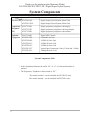
System Components
Model
Service Unit KX-TD816SL
KX-TD1232SL
Proprietary KX-T7230SL
Telephone
KX-T7235SL
(PT)
KX-T7250SL
Optional
Equipment
KX-T7240SL
KX-TD170SL
KX-TD280SL
KX-TD281G*1
KX-TD282G*2
KX-TD192G*1
KX-TD196G*1
Description
Digital Super Hybrid System (Main Unit)
Digital Super Hybrid System (Main Unit)
Digital proprietary telephone with display
Digital proprietary telephone with large display
Digital proprietary telephone with monitor
Digital DSS Console
8-Station Line Unit
2-ISDN S0 Line Unit
4-ISDN S0 Line Card
2-ISDN S0 Line Card
System Inter Connection Cards (2 Cards and 1 Cable)
2400bps Remote Card
System Components Table
• In this Installation Manual, the suffix “SL” or “G” of each model number is
omitted.
• The Proprietary Telephone is abbreviated as “PT.”
The models marked *1 can be installed in KX-TD1232 only.
The models marked *2 can be installed in KX-TD816 only.
2
Attention
• Keep the unit away from heating appliances and electrical noise generating devices
such as fluorescent lamps, motors and television. These noise sources can interfere
with the performance of the Digital Super Hybrid System.
• This unit should be kept free of dust, moisture, high temperature (more than 40˚C /
104˚F) and vibration, and should not be exposed to direct sunlight.
• Never attempt to insert wires, pins, etc. into the vents or other holes of this unit.
• If there is any trouble, disconnect the unit from the telephone line. Plug the telephone
directly into the telephone line. If the telephone operates properly, do not reconnect
the unit to the line until the trouble has been repaired. If the telephone does not operate
properly, chances are that the trouble is in the telephone system, and not in the unit.
• Do not use benzine, thinner, or the like, or any abrasive powder to clean the cabinet.
Wipe it with a soft cloth.
• This unit may only be installed and serviced by Qualified Service Personnel.
WARNING
• THIS UNIT IS EQUIPPED WITH AN EARTHING CONTACT PLUG. FOR SAFETY
REASONS THIS PLUG MUST ONLY BE CONNECTED TO AN EARTHING
CONTACT SOCKET WHICH HAS BEEN INSTALLED ACCORDING TO
REGULATIONS.
• THE POWER SOCKET WALL OUTLET SHOULD BE LOCATED NEAR THIS
EQUIPMENT AND BE EASILY ACCESSIBLE.
• TO PREVENT FIRE OR SHOCK HAZARD, DO NOT EXPOSE THIS PRODUCT TO
RAIN OR ANY TYPE OF MOISTURE.
The serial number of this product may be found on the label affixed to the bottom
of the unit. You should note the serial number of this unit in the space provided
and retain this book as a permanent record of your purchase to aid in identification
in the event of theft.
MODEL NO.:
SERIAL NO.:
For your future reference
DATA OF PURCHASE
NAME OF DEALER
DEALER’S ADDRESS
3
Introduction
This Installation Manual provides technical information for the Panasonic Digital
Super Hybrid System, KX-TD816/KX-TD1232. It is designed to serve as an overall
technical reference for the system and includes a description of the system, its
hardware and software, features and services and environmental requirements.
This manual contains the following sections:
Section 1, System Outline.
Provides general information on the system including system capacity and
specifications.
Section 2, Installation.
Contains the basic system installation and wiring instructions, as well as how to
install the optional cards and units.
Section 3, Features.
Describes all the basic, optional and programmable features in alphabetical order. It
also provides information about the programming required, conditions, connection
references, related features and operation for every feature.
Section 4, System Programming.
Provides step-by-step programming instructions for a proprietary telephone.
Section 5, List.
Lists tone/ring tone and default values of system programming.
Section 6, Troubleshooting
Provides information for system and telephone troubleshooting.
NOTE
The following document may be used in conjunction with this manual:
• User Manual for KX-TD816/KX-TD1232 System, Proprietary Telephones, DSS
Console and Single Line Telephones
4
Contents
Section 1, System Outline
1.1
1.2
1.3
1.4
1.5
System Highlights .............................................................................
Basic System Construction...............................................................
Proprietary Telephones / Proprietary Single Line Telephone ......
Options ...............................................................................................
1.4.1 Station Line Unit (KX-TD170) ...............................................
1.4.2 CO Line / ISDN S0 Line Card (KX-TD181 / KX-TD182)*1..
1.4.3 CO Line / ISDN S0 Line Card (KX-TD281/KX-TD282)*2....
1.4.4 CO Line / ISDN S0 Line Unit
(KX-TD180, KX-TD280, KX-TD283)...................................
1.4.5 System Inter Connection Cards (KX-TD192)*1 ......................
1.4.6 Remote Card (KX-TD196)*1...................................................
1.4.7 DSS Console (KX-T7240 / KX-T7040)..................................
Specifications .....................................................................................
1.5.1 General Description.................................................................
1.5.2 Characteristics .........................................................................
1.5.3 System Capacity......................................................................
1-2
1-4
1-5
1-6
1-6
1-6
1-6
1-6
1-7
1-7
1-8
1-9
1-9
1-10
1-11
Section 2, Installation
2.1
2.2
2.3
Before Installation.............................................................................
Installation of the Main Unit............................................................
2.2.1 Unpacking ...............................................................................
2.2.2 Name and Location .................................................................
2.2.3 Wall Mounting.........................................................................
2.2.4 Frame Ground Connection ......................................................
2.2.5 Opening Front Cover...............................................................
Connection .........................................................................................
2.3.1 System Connection Diagram...................................................
2.3.2 Extension Connection
for Proprietary Telephones, Single Line Telephones and DSS Consoles..
2.3.3 Optional Extension Connection of Clip Terminal .................
2.3.4 Paralleled Telephone Connection
*1
for Proprietary Telephone and a Single Line Telephone ............................
2-2
2-4
2-4
2-4
2-6
2-7
2-8
2-9
2-9
2-11
2-16
2-18
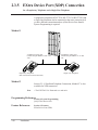
2.3.5 EXtra Device Port (XDP) Connection
for a Digital Proprietary Telephone and a Single Line Telephone .............
2.3.6 Polarity Sensitive Telephone Connection ...............................
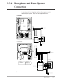
2.3.7 Doorphone and Door Opener Connection...............................
2.3.8 External Relay, External Ringer and
External Sensor Connection ....................................................
2.3.9 External Pager (Paging Equipment) Connection ....................
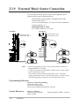
2.3.10 External Music Source Connection.........................................
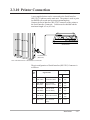
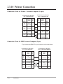
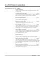
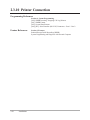
2.3.11 Printer Connection ..................................................................
*1 : Available for KX-TD1232 only.
*2 : Available for KX-TD816 only.
2-20
2-21
2-22
2-24
2-26
2-27
2-28
5
Contents
2.4
2.5
2.6
2.7
2.8
Optional Cards and Units Installation............................................
2.4.1 Location of Optional Cards and Units.....................................
2.4.2 CO Line Connection (Optional Card) .....................................
2.4.3 Lightning Protector Installation ..............................................
2.4.4 CO Line Connection (Optional Unit)......................................
2.4.5 Extension Connection .............................................................
2.4.6 Installing Expansion Unit
(KX-TD170 / KX-TD180 / KX-TD280 / KX-TD283) ...........
2.4.7 Remote Card Installation*........................................................
2.4.8 System Connection*.................................................................
Power Failure Transfer Connection................................................
Starting the System for the First Time ...........................................
System Restart...................................................................................
System Data Clear.............................................................................
2-32
2-32
2-34
2-36
2-39
2-39
2-40
2-44
2-45
2-47
2-48
2-49
2-50
Section 3, Features
A
B
C
6
Absent Message Capability ................................................................
Account Code Entry ...........................................................................
Alternate Calling – Ring / Voice.........................................................
Alert Indication...................................................................................
Answering, Direct CO Line................................................................
Automatic Adjustment Time ..............................................................
Automatic Callback Busy (Camp-On) ...............................................
Automatic Error Logging ...................................................................
Automatic Overflow and Hurry-Up Transfer .....................................
Automatic Redial → Redial, Automatic.............................................
Automatic Station Release..................................................................
Background Music (BGM) .................................................................
Background Music (BGM) – External ...............................................
Budget Management...........................................................................
Busy Lamp Field ................................................................................
Busy Station Signaling (BSS) ............................................................
Button, Direct Station Selection (DSS) .............................................
Button, Flexible ..................................................................................
Button, Group-CO (G-CO).................................................................
Button, Loop-CO (L-CO) ...................................................................
Button, Single-CO (S-CO) .................................................................
Buttons on Proprietary Telephones.....................................................
CALL FORWARDING FEATURES – SUMMARY .........................
Call Forwarding – All Calls................................................................
Call Forwarding – Busy......................................................................
Call Forwarding – Busy / No Answer ................................................
3-2
3-2
3-4
3-4
3-5
3-5
3-6
3-6
3-7
3-99
3-8
3-8
3-9
3-10
3-10
3-11
3-11
3-12
3-13
3-14
3-15
3-16
3-18
3-18
3-19
3-20
:Available for KX-TD1232 only.
*
Contents
D
Call Forwarding – Follow Me ............................................................
Call Forwarding – No Answer............................................................
Call Forwarding – to CO Line............................................................
Call Hold – CO Line...........................................................................
Call Hold – Intercom ..........................................................................
Call Hold, Exclusive – CO Line.........................................................
Call Hold, Exclusive – Intercom ........................................................
Call Hold Retrieve – CO Line ............................................................
Call Hold Retrieve – Intercom............................................................
Call Log, Incoming.............................................................................
Call Park .............................................................................................
Call Pickup, CO Line .........................................................................
Call Pickup, Directed..........................................................................
Call Pickup, Group .............................................................................
Call Pickup Deny................................................................................
Call Splitting.......................................................................................
CALL TRANSFER FEATURES – SUMMARY ...............................
Call Transfer, Screened – to CO Line.................................................
Call Transfer, Screened – to Extension ..............................................
Call Transfer, Unscreened – to Extension ..........................................
Call Waiting ........................................................................................
Call ID ................................................................................................
Calling Line Identification Restriction (CLIR) ..................................
Calling Party Control (CPC) Signal Detection...................................
Charge Fee Reference.........................................................................
Class of Service (COS).......................................................................
CO Line Connection Assignment.......................................................
CO Line Connection Assignment – Outgoing....................................
CO Line Group ..................................................................................
CO Line Name Display ......................................................................
Conference..........................................................................................
Conference, Unattended .....................................................................
Confirmation Tone..............................................................................
Connected Line Identification Restriction (COLR) ...........................
Data Line Security ..............................................................................
Delayed Ringing → Ringing, Delayed...............................................
Department Codes ..............................................................................
Dial Tone, Distinctive.........................................................................
Dial Type Selection ............................................................................
Direct Dialing In (DDI) ......................................................................
Direct In Lines (DIL)..........................................................................
Direct Station Selection (DSS) Button → Button, Direct Station
Selection (DSS) .......................................................................
3-21
3-21
3-22
3-23
3-23
3-24
3-24
3-25
3-25
3-26
3-27
3-28
3-28
3-28
3-29
3-29
3-30
3-30
3-31
3-31
3-32
3-33
3-34
3-34
3-35
3-36
3-37
3-37
3-38
3-39
3-39
3-40
3-40
3-42
3-43
3-101
3-43
3-44
3-45
3-46
3-46
3-11
7
Contents
E
F
G
H
Directed Call Pickup → Call Pickup, Directed ..................................
Display, Call Information ...................................................................
Display, Self-Extension Number ........................................................
Display, Time and Date ......................................................................
Display Contrast Adjustment..............................................................
Do Not Disturb (DND) .......................................................................
Do Not Disturb for Direct Dialing In Call..........................................
Do Not Disturb (DND) Override........................................................
Door Opener .......................................................................................
Doorphone Call...................................................................................
DSS Console (KX-T7240 / KX-T7040).............................................
Electronic Station Lockout .................................................................
Emergency Call ..................................................................................
End-to-End DTMF Signaling (Tone Through)...................................
Executive Busy Override – CO Line..................................................
Executive Busy Override – Extension................................................
Extension Connection Assignment.....................................................
Extension Group .................................................................................
External Feature Access .....................................................................
External Relay ....................................................................................
External Ringer...................................................................................
External Sensor...................................................................................
EXtra Device Port (XDP) ...................................................................
Flash....................................................................................................
Flexible Button → Button, Flexible ...................................................
Flexible Numbering............................................................................
Floating Station ..................................................................................
Full One-Touch Dialing......................................................................
Group Call Pickup → Call Pickup, Group..........................................
Group CO (G-CO) Button → Button, Group-CO (G-CO).................
Handset / Headset Selection................................................................
Handsfree Answerback .......................................................................
Handsfree Operation...........................................................................
Hold Recall .........................................................................................
Host PBX Access................................................................................
HOTEL APPLICATION ....................................................................
Check - In / Check - Out.....................................................................................
Timed Reminder, Remote (Wake-Up Call) ........................................................
I
8
Hurry-Up Transfer → Automatic Overflow and Hurry-Up Transfer.
Incoming Call Log → Call Log, Incoming.........................................
Intercept Routing ................................................................................
Intercom Calling .................................................................................
3-28
3-47
3-48
3-49
3-49
3-50
3-51
3-51
3-52
3-52
3-53
3-56
3-56
3-57
3-57
3-58
3-59
3-59
3-60
3-60
3-61
3-62
3-63
3-63
3-12
3-64
3-67
3-68
3-28
3-13
3-68
3-69
3-69
3-70
3-70
3-71
3-71
3-72
3-7
3-26
3-73
3-73
Contents
L
M
N
O
P
R
Last Number Redial → Redial, Last Number.....................................
LED Indication, CO Line ...................................................................
LED Indication, Intercom...................................................................
Line Access, Automatic......................................................................
Line Access, CO Line Group ............................................................
Line Access, Direct.............................................................................
Line Access, Individual ......................................................................
Line Preference – Incoming (No Line / Prime Line / Ringing Line) .
Line Preference – Outgoing (Idle Line / No Line / Prime Line) ........
Lockout...............................................................................................
Log-In / Log-Out ................................................................................
Loop-CO (L-CO) Button → Button, Loop-CO (L-CO).....................
Manager Extension .............................................................................
Message Waiting.................................................................................
Microphone Mute ...............................................................................
Mixed Station Capacities....................................................................
Module Expansion..............................................................................
Music on Hold ....................................................................................
Night Service ......................................................................................
Notebook Function .............................................................................
Off-Hook Monitor...............................................................................
One-Touch Dialing..............................................................................
One-Touch Transfer by DSS Button...................................................
Operator ..............................................................................................
Operator Call ......................................................................................
PAGING FEATURES – SUMMARY.................................................
Paging – All ........................................................................................
Paging – External................................................................................
Paging – Group...................................................................................
Paralleled Telephone...........................................................................
Pause Insertion, Automatic.................................................................
Pickup Dialing ....................................................................................
Power Failure Restart .........................................................................
Power Failure Transfer .......................................................................
Predial ................................................................................................
Privacy, Automatic .............................................................................
Private Call .........................................................................................
Pulse to Tone Conversion ...................................................................
Redial, Automatic ..............................................................................
Redial, Last Number ..........................................................................
Redial, Saved Number .......................................................................
Remote Station Lock Control .............................................................
3-100
3-74
3-75
3-76
3-77
3-77
3-78
3-79
3-80
3-81
3-81
3-14
3-82
3-82
3-83
3-84
3-84
3-85
3-86
3-87
3-87
3-88
3-89
3-89
3-90
3-91
3-91
3-92
3-93
3-93
3-94
3-95
3-96
3-96
3-97
3-97
3-98
3-98
3-99
3-100
3-100
3-101
9
Contents
S
Ringing, Delayed ................................................................................
Ringing, Discriminating .....................................................................
Ringing Tone Selection for CO Buttons.............................................
Saved Number Redial → Redial, Saved Number...............................
Screened Call Transfer – to CO Line
→ Call Transfer, Screened – to CO Line ................................
Screened Call Transfer – to Extension
→ Call Transfer, Screened – to Extension ..............................
Secret Dialing .....................................................................................
Single-CO (S-CO) Button → Button, Single-CO (S-CO) .................
Special Features for KX-T7235..........................................................
Call Log, Outgoing .......................................................................................
Extension Dialing .........................................................................................
Station Speed Dialing ...................................................................................
System Feature Access Menu.......................................................................
System Speed Dialing...................................................................................
T
U
V
10
Station Feature Clear ..........................................................................
Station Hunting...................................................................................
Station Message Detail Recording (SMDR) .....................................
Station Programming..........................................................................
Station Programming Data Default Set ..............................................
Station Speed Dialing .........................................................................
System Connection* ............................................................................
System Data Default Set.....................................................................
System Programming and Diagnosis with Personal Computer..........
System Programming with Proprietary Telephone.............................
System Speed Dialing.........................................................................
Terminate ............................................................................................
Time-Out, Variable .............................................................................
Timed Reminder .................................................................................
Toll Restriction ...................................................................................
Toll Restriction Override by Account Code Entry .............................
Toll Restriction Override for System Speed Dialing..........................
Trunk (CO Line) Answer From Any Station (TAFAS) .....................
Unattended Conference → Conference, Unattended..........................
Uniform Call Distribution (UCD).......................................................
Unscreened Call Transfer – to Extension
→ Call Transfer, Unscreened – to Extension ..........................
Voice Mail Integration ........................................................................
Volume Control – Speaker / Ringer....................................................
*
3-101
3-102
3-102
3-100
3-30
3-31
3-103
3-15
3-104
3-104
3-104
3-105
3-105
3-106
3-107
3-108
3-108
3-111
3-112
3-112
3-113
3-114
3-115
3-116
3-117
3-117
3-118
3-120
3-120
3-127
3-128
3-128
3-40
3-129
3-31
3-131
3-137
: Available for KX-TD1232 only.
Contents
Section 4, System Programming
4.1
4.2
4.3
*
General Programming Instructions ................................................
4.1.1 Using the Proprietary Telephone.............................................
4.1.2 Programming Ways .................................................................
4.1.3 Entering Characters .................................................................
4.1.4 Example of Programming .......................................................
Manager Programming ....................................................................
[000] Date and Time Set ...................................................................
[001] System Speed Dialing Number Set .........................................
[002] System Speed Dialing Name Set.............................................
[003] Extension Number Set.............................................................
[004] Extension Name Set ................................................................
[005] Flexible CO Button Assignment .............................................
[006] Operator / Manager Extension Assignment – Day / Night .....
[007] DSS Console Port and Paired Telephone Assignment ...........
[008] Absent Messages .....................................................................
[009] Emergency Dial Number Set...................................................
[010] Budget Management ...............................................................
[011] Charge Margin Rate ................................................................
System Programming .......................................................................
[100] Flexible Numbering ................................................................
[102] Day / Night Service Starting Time ..........................................
[103] Automatic Access CO Line Group Assignment .....................
[105] Account Codes ........................................................................
[106] Station Hunting Type ..............................................................
[107] System Password.....................................................................
[108] One-Touch Transfer by DSS Button .......................................
[109] Expansion Card / Unit Type ....................................................
[113] VM Status DTMF Set .............................................................
[114] VM Command DTMF Set ......................................................
[115] Adjust Time* ............................................................................
[116] ROM Version Display .............................................................
[117] Charge Display Selection ........................................................
[118] Charge Verification Assignment .............................................
[119] Charge Verification ID Code Set.............................................
[120] Operator Queue .......................................................................
[121] Pulse Dial Reception Assignment ...........................................
[122] Automatic Door Open Assignment .........................................
[123] Hotel Application ....................................................................
: Available for KX-TD1232 only.
4-2
4-3
4-7
4-9
4-12
4-14
4-14
4-16
4-18
4-19
4-21
4-23
4-25
4-26
4-28
4-29
4-30
4-31
4-32
4-32
4-35
4-37
4-38
4-39
4-40
4-41
4-42
4-43
4-45
4-47
4-48
4-49
4-50
4-51
4-52
4-53
4-54
4-55
11
Contents
4.4
4.5
4.6
4.7
12
Timer Programming .........................................................................
[200] Hold Recall Time ....................................................................
[201] Transfer Recall Time...............................................................
[202] Call Forwarding – No Answer Time.......................................
[203] Intercept Time .........................................................................
[204] Pickup Dial Waiting Time .......................................................
[207] First Digit Time .......................................................................
[208] Inter Digit Time.......................................................................
[209] Automatic Redial Repeat Times..............................................
[210] Automatic Redial Interval Time..............................................
[211] Dial Start Time ........................................................................
[212] Call Duration Count Start Time ..............................................
[213] External Relay Connecting Time ............................................
[214] Message Waiting Ring Interval Time......................................
[215] Ring-Off Detection Time ........................................................
TRS Programming............................................................................
[301]–[305] TRS Denied Code Entry for Levels 2 through 6...........
[306]–[310] TRS Excepted Code Entry for Levels 2 through 6........
CO Line Programming.....................................................................
[400] CO Line Connection Assignment ...........................................
[401] CO Line Group Assignment....................................................
[402] Dial Mode Selection................................................................
[404] DTMF Time ............................................................................
[405] CPC Signal Detection Incoming Set .......................................
[407]–[408] DIL 1:1 Extension — Day / Night ................................
[409]–[410] Intercept Extension — Day / Night...............................
[411] Host PBX Access Codes .........................................................
[412] Pause Time ..............................................................................
[413] Flash Time...............................................................................
[414] Disconnect Time......................................................................
[415] CPC Signal Detection Outgoing Set .......................................
[417] Tone Detection ........................................................................
[418] External Ringer Assignment ...................................................
[419] Subscriber Number Assignment..............................................
[420] Direct Dialing In......................................................................
[421] CO Line Name Assignment ....................................................
COS Programming ...........................................................................
[500]–[501] Toll Restriction Level — Day / Night ...........................
[503] Call Transfer to CO Line.........................................................
[504] Call Forwarding to CO Line ...................................................
[505] Executive Busy Override ........................................................
4-56
4-56
4-57
4-58
4-59
4-60
4-61
4-62
4-63
4-64
4-65
4-66
4-67
4-68
4-69
4-70
4-70
4-71
4-72
4-72
4-73
4-74
4-75
4-76
4-77
4-78
4-79
4-81
4-82
4-83
4-84
4-86
4-87
4-88
4-89
4-90
4-91
4-91
4-92
4-93
4-94
Contents
[506] Executive Busy Override Deny...............................................
[507] Do Not Disturb Override.........................................................
[508] Account Code Entry Mode......................................................
[509]-[510] Toll Restriction Level for System Speed Dialing
–Day / Night ..................................................................
[511] Door Opener Access................................................................
[512] External Relay Access.............................................................
[513] Night Service Access ..............................................................
[514] Do Not Disturb for Direct Dialing In Call ..............................
[516] Calling Line Identification Restriction....................................
[517] Connected Line Identification Restriction ..............................
4.8 Extension Programming...................................................................
[600] EXtra Device Port ...................................................................
[601] Class of Service.......................................................................
[602] Extension Group Assignment .................................................
[603]–[604] DIL 1:N Extension and Delayed Ringing
— Day / Night .........................................................................
[605]–[606] Outgoing Permitted CO Line Assignment
— Day / Night .........................................................................
[607]–[608] Doorphone Ringing Assignment — Day / Night ..........
[609] Voice Mail Access Codes ........................................................
[610] Department Codes ...................................................................
[611] Extension Connection Assignment .........................................
[612] Data Line Security...................................................................
4.9 Resource Programming....................................................................
[800] SMDR Incoming / Outgoing Call Log Printout ......................
[801] SMDR Format .........................................................................
[802] System Data Printout...............................................................
[803] Music Source Use....................................................................
[804] External Pager BGM ...............................................................
[805] External Pager Confirmation Tone..........................................
[806]–[807] Serial Interface (RS-232C) Parameters
— Port 1 / Port 2 .....................................................................
[813] Floating Number Assignment .................................................
[814] Modem Standard* ....................................................................
4.10 Option Programming........................................................................
[990] System Additional Information...............................................
[991] COS Additional Information...................................................
[992] CO Line Group Additional Information..................................
*
: Available for KX-TD1232 only.
4-95
4-96
4-97
4-98
4-99
4-100
4-101
4-102
4-103
4-104
4-105
4-105
4-106
4-108
4-109
4-111
4-113
4-114
4-115
4-117
4-118
4-119
4-119
4-120
4-121
4-122
4-123
4-124
4-125
4-127
4-129
4-130
4-130
4-135
4-137
13
Contents
Section 5, List
5.1
5.2
Tone / Ring Tone................................................................................
Default Values....................................................................................
5-2
5-4
Section 6, Trouble shooting
6.1
14
Trouble shooting................................................................................
6.1.1 Installation ...............................................................................
6.1.2 Connection...............................................................................
6.1.3 Operation .................................................................................
6.1.4 Using Rest Button....................................................................
6-2
6-2
6-3
6-4
6-5
Section 1
System Outline
This section provides general information on the system,
including system capacity and specifications.
1.1
System Highlights
System Capacity
KX-TD816
KX-TD1232
ISDN S0 line
Extension
ISDN S0 line
Extension
Basic
System
0
8
0
16
Module
Expansion
4
16
6
32
System
Connection
—
—
12
64
Module Expansion
Expansion modules are used to increase the system capacity.
Extension modules and ISDN modules can be added to the basic
system to add extensions and ISDN lines.
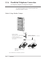
EXtra Device Port (XDP)
Each extension jack in the system supports the connection of a
proprietary telephone/DSS Console and a single line device. The
devices have different extension numbers and are treated as two
completely different extensions.
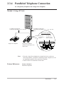
Paralleled Telephone Connection
Every jack in the system also supports the parallel connection of a
proprietary telephone and a single line device. They share the same
extension number and are considered by the system to be one
extension.
Super Hybrid System
This system supports the connection of proprietary telephones, DSS
Consoles and single line devices such as single line telephones,
facsimiles, and data terminals.
System Connection*
With the addition of optional System Inter Connection Card, two
Digital Super Hybrid Systems can be connected together to expand
the system capacity. The two systems function as one, however,
some functions such as paging and music on hold are duplicated.
Proprietary Telephones (PT)
The system supports three different models of proprietary
telephones.
Programming System
The system can be programmed from a proprietary telephone or
from a personal computer.
1-2
System Outline
*: Available for KX-TD1232 only.
1.1
System Highlights
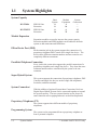
Trunk (CO Line) Answer From Any Station (TAFAS)
Ringing occurs over the external paging system; call can be
answered from any station.
Charge Fee Reference
Allows the user to see charges and to print out the charges.
Budget Management
Limits the telephone usage to a pre-assigned amount.
Hotel Application
Allows to handle the front and operator services such as checkin/check-out and wake-up call setting.
Uniform Call Distribution (UCD)
Allows an incoming calls to be distributed uniformly to a specific
group of extensions.
System Outline
1-3
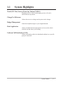
1.2
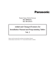
Basic System Construction
The KX-TD816 has a basic capacity of eight extensions, and the
KX-TD1232 has a basic capacity of 16 extensions. It is capable of
supporting Panasonic proprietary telephones, DSS Consoles and
single line devices such as single line telephones, facsimiles.
To expand its capabilities the system can be equipped with optional
components or customer-supplied peripherals such as external
speakers and external music sources (e.g., radios).
D1232
DIGITAL SUPE
R HYBRID SYST
EM
D816
DIGITAL SUPE
R HYBRID SYST
EM
Panaso
nic
KX-TD816
1-4
System Outline
Panaso
nic
KX-TD1232
1.3
Proprietary Telephones/Proprietary
Single Line Telephone
The following Panasonic proprietary telephones (PT) are available
with this system.
Proprietary
Telephone
KX-T7230
KX-T7235
KX-T7250
Note:
Description
Digital, display, speakerphone, 24 CO
Digital, large display, speakerphone, 12 CO
Digital, monitor, 6 CO
CO: CO line access button
System Outline
1-5
1.4
1.4.1
Options
Station Line Unit (KX-TD170)
Each unit adds eight extensions. One unit for KX-TD816 and
up to two units for KX-TD1232 can be installed per system.
D1232
DIGITAL SUPER HYBRID SYSTEM
D816
DIGITAL SUPER HYBRID SYSTEM
Panasonic
Panasonic
8 extensions can be added.
8 or 16 extensions can be added.
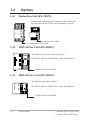
1.4.2
ISDN S0 Line Card (KX-TD281)*1
The following card can be installed per system.
KX-TD281: Adds four ISDN S0 lines. (Basic Rate Interface)
4 ISDN S0 lines can be added.
1.4.3
ISDN S0 Line Card (KX-TD282)*2
The following card can be installed.
KX-TD282: Adds two ISDN S0 lines. (Basic Rate Interface)
2 ISDN S0 lines can be added.
1-6
System Outline
*1
*2
: Available for KX-TD1232 only.
: Available for KX-TD816 only.
1.4
Options
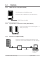
1.4.4
ISDN S0 Line Unit (KX-TD280)
D1232
DIGITAL SUPER HYBRID SYSTEM
The following unit can be installed per system.
KX-TD280: Adds two ISDN S0 lines. (Basic Rate Interface)
Panasonic
2 ISDN S0 lines can be added.
Note: The KX-TD1232 is illustrated as a main unit.
1.4.5
System Inter Connection Cards (KX-TD192)*
D1232
DIGITAL SUPER
Panas
HYBRID SYSTEM
onic
D1232
DIGITAL SUPER
Permits two KX-TD1232 to be connected together — to
double system capacity.
HYBRID SYSTEM
Panas
onic
Connection Cable
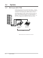
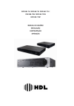
1.4.6
Remote Card (KX-TD196)*
D1232
DIGITAL SUPER
HYBRID SYSTEM
The Remote Card allows programming and maintenance of the
system from a remote location. (Baud Rate: 300 / 1200 / 2400 bps)
Panasonic
Central
Office
Telephone Line
Personal Computer
with Modem
*
: Available for KX-TD1232 only.
System Outline
1-7
1.4
Options
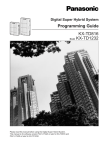
1.4.7
DSS Console (KX-T7240)
D1232
DIGITAL SUPER
HYBRID SYSTEM
Permits easy and quick access to stations and features. The Busy
Lamp Field (BLF) shows the idle, busy or Do Not Disturb state of
each station. If the Operator uses a DSS Console as well as a
proprietary telephone, the BLF will show the check-in/check-out
status. DSS Consoles are designed for use with a proprietary
telephone. The KX-TD816 supports up four DSS Consoles. The
KX-TD1232 supports up to eight DSS Consoles per system.
DIG
ITA
L
Pana
sonic
DIG
ITAL
Pan
ason
ic
Panaso
nic
Paired Telephone
(Proprietary
Telephone)
DSS Console
KX-T7240
Pair
Note: The KX-TD1232 is illustrated as a main unit.
1-8
System Outline
1.5
Specifications
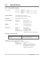
1.5.1 General Description
System Capacity
KX-TD816 — ISDN S0 lines
Stations
KX-TD1232 — ISDN S0 lines
Stations
4 max.
16 max. (32 max. with XDP)
6 max.
32 max. (64 max. with XDP)
Control Method
Stored Program CPU: 16 bits CPU
Control ROM: 1 MB, Control RAM: 256KB
Switching
Non Blocking PCM Time Switch
Power Supplies
Primary Power
Secondary
230 VAC, 50 Hz
Station Supply Volt: 30V
Circuit Volt: ± 5V, ± 15V
Dialing
Internal
Dial Pulse (DP) 10 pps
Tone (DTMF) Dialing
Connector
ISDN S0 lines
Stations
Paging Output
External Music Input
4-pin Connector
Amphenol Connector
Pin Jack (RCA JACK)
Two-conductors Jack
(MINIJACK 3.5 mm/9/64 inch diameter)
Extension Connection Cable
Single line telephones
KX-T7230, KX-T7235, KX-T7240,
KX-T7250
1 pair wire (T, R)
1 pair wire (D1, D2): T and R are not necessary.
or 2 pair wire (T, R, D1, D2)
SMDR (Station Message Detail Recording)
Interface
Output Equipment
Detail Recording
V. 24 (RS-232C)
Printer
Date, Time, Extension Number,
Department Code, CO Line Number,
Dialed Number, Call Duration,
Charge Fee, Account Code
System Outline
1-9
1.5
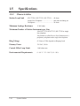
1.5.2
Specifications
Characteristics
Station Loop Limit
KX-T7230 / KX-T7235 / KX-T7250.......40 ohms
Single Line Telephone .............................600 ohms including set
Doorphone................................................20 ohms
Minimum Leakage Resistance
15 000 ohms
Maximum Number of Station Instruments per Line
1 for KX-T7230, KX-T7235, KX-T7250 or single
line telephone
2 by Parallel or eXtra Device Port Connection of a
proprietary telephone and a single line telephone
Ring Voltage
65 Vrms at 32 Hz depends on Ringing Load
Primary Power
230 VAC, 50 Hz
Central Office Loop Limit
1 600 ohms max.
Environmental Requirements
0 – 40 °C / 32 – 104 °F, 10 – 90%
1-10
System Outline
1.5
Specifications
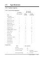
1.5.3 System Capacity
Lines, Cards, Station Equipment
KX-TD816
Max. Quantity
Item
KX-TD1232
Max. Quantity
Single
System
System
Connection
System Inter
Connection Card
—
—
2
Service Unit
1
1
2
ISDN S0 Line Card
1
1
2
ISDN S0 Line Unit
1
1
2
ISDN S0 Line
(Baud Rate Interface)
4
6
12
Station Line Unit
1
2
4
Extension Jack
16
32
64
Station Terminal
(including DSS Consoles)
32
64
128
{DSS Console}
{4}
{8}
{16}
Remote Card
—
1
1
Doorphone
1
1
2
Door Opener
2
2
4
External Music Source
2
2
4
External Pager
2
2
4
External Relay
1
1
2
External Ringer
1
1
2
External Sensor
1
1
2
System Data
Item
Max. Quantity
Operator
2
System Speed Dialing
500
One-Touch Dialing
24
per station
(proprietary telephone)
Station Speed Dialing
10
per station
System Outline
1-11
1.5
Specifications
Call Park
10
Absent Message
9
CO Line Group
8
Toll Restriction Level
8
Extension Group
8
Class of Service
8
Message Waiting
128
Uniform Call Distribution Group 8
1-12
System Outline
Section 2
Installation
This section contains the basic system installation and wiring
instructions, as well as how to install the optional cards and
units.
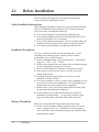
2.1
Before Installation
Please read the following notes concerning installation and
connection before installing the system.
Safety Installation Instructions
When installing telephone wiring, basic safety precautions should
always be followed to reduce the risk of fire, electric shock and
injury to persons, including the following:
1. Never install telephone wiring during a lightning storm.
2. Never install telephone jacks in wet locations unless the jack is
specifically designed for wet locations.
3. Never touch uninsulated telephone wires or terminals unless the
telephone line has been disconnected at the network interface.
4. Use caution when installing or modifying telephone lines.
Installation Precautions
This set is exclusively made for wall mounting only. Avoid
installing in the following places. (Doing so may result in
malfunction, noise, or discoloration.)
1. In direct sunlight and hot, cold, or humid places. (Temperature
range: 0°C – 40°C / 32°F – 104°F)
2. Sulfuric gases produced in areas where there are thermal springs,
etc. may damage the equipment or contacts.
3. Places in which shocks or vibrations are frequent or strong.
4. Dusty places, or places where water or oil may come into
contact with the unit.
5. Near high-frequency generating devices such as sewing
machines or electric welders.
6. On or near computers, telexes, or other office equipment, as well
as microwave ovens or air conditioners. (It is preferable not to
install in the same room with the above equipment.)
7. Install at least 1.8 m (6 feet) from radios and televisions. (both
the main unit and proprietary telephones)
8. Do not obstruct area around the main unit (for reasons of
maintenance and inspection — be especially careful to allow
space for cooling above and at the sides of the main unit).
Wiring Precautions
Make sure to keep the following instructions when wiring.
1. Do not wire the telephone cable in parallel with an AC power
source, computer, telex, etc. If the cables are run near those
wires, shield the cables with metal tubing or use shielded cables
and ground the shields.
2-2
Installation
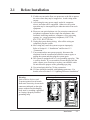
2.1
Before Installation
2. If cables are run on the floor, use protectors or the like to protect
the wires where they may be stepped on. Avoid wiring under
carpets.
3. Avoid using the same power supply outlet for computers,
telexes, and other office equipment. Otherwise, the system
operation may be interrupted by the induction noise from such
equipment.
4. Please use one pair telephone wire for extension connection of
(telephone) equipment such as single line telephones, data
terminals, answering machines, computers, voice processing
systems, etc., except proprietary telephones ( KX-T7230,
KX-T7235, KX-T7250 etc.).
5. Unplug the system during wiring. After all the wiring are
completed, plug the system.
6. Mis-wiring may cause the system to operate improperly.
Refer to Section 6.1.1 “Installation” and Section 6.1.2
“Connection.”
7. If an extension does not operate properly, disconnect the
telephone from the extension line and then connect again, or
unplug the system and then plug the system again.
8. The system is equipped with a 3-wire grounding type plug. This
is a safety feature. If you are unable to insert the plug into the
outlet, contact your electrician to replace your obsolete outlet.
Do not defeat the purpose of the grounding-type plug.
9. Use twisted pair cable for CO line connection.
10. CO lines should be installed with lightning protectors. For
details, refer to Section 2.4.3 “Lightning Protectors Installation.”
Warning:
Static sensitive devices used.
To protect printed circuit boards
from static electricity, do not touch
connectors indicated on the right
picture without first discharging
body static by touching a grounded
or wearing a properly installed
grounding strap.
Warning : Static sensitive connectors
Installation
2-3
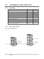
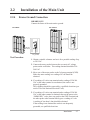
2.2
2.2.1
Installation of the Main Unit
Unpacking
Main Unit
AC Cord
Templet
Screw
Anchor Plug
Pager Connector
Music Source Connector
Doorphone, Door Opener Connector
Expansion Line Cord Holder
Ferrite Core
User Manual
Reference Manual for Single Line Telephone
Overlay for a proprietary telephone
2.2.2
KX-TD816
one
one
one
three
three
two
two
five
one
—
one
one
one
KX-TD1232
one
one
one
four
four
two
two
five
one
two
one
one
one
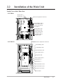
Name and Location
Overview of the Main Unit
D1232
DIGITAL SUPER
HYBRID SYSTE
M
D816
DIGITAL SUPER
HYBRID SYSTE
M
Ground Terminal
Power Indicator
Serial Interface
(RS-232C)
Ground Terminal
Power Indicator
AC Inlet
Panaso
nic
Panaso
nic
KX-TD816
2-4
Installation
KX-TD1232
Serial Interface
(RS-232C)
AC Inlet
2.2
Installation of the Main Unit
Inside View of the Main Unit
KX-TD816
Paging Jack 2
Paging Jack 1
Extension Amphenol Connectors
External Music Jack 2
External Music Jack 1
System Clear Switch
Reset Button
External Relay Jack
Central Ringer Jack
External Sensor Jack
Door Opener Jack 1
Door Opener Jack 2
Doorphone Jack
KX-TD1232
Extension Amphenol Connectors
External Relay Jack
Central Ringer Jack
External Sensor Jack
Door Opener Jack 1
Doorphone Jack
Door Opener Jack 2
Paging Jack 2
Paging Jack 1
External Music Jack 2
External Music Jack 1
System Clear Switch
Reset Button
Installation
2-5
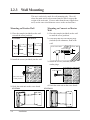
2.2.3 Wall Mounting
This set is exclusively made for wall mounting only. The wall
where the main unit is to be mounted must be able to support the
weight of the main unit. If screws other than the ones supplied are
used, use the same-sized diameter screws as the enclosed ones.
Mounting on Wooden Wall
Mounting on Concrete or Mortar
Wall
1. Place the templet (included) on the wall
to mark the screw positions.
1. Place the templet (included) on the wall
to mark the screw positions.
KX-TD816
KX-TD1232
2. Drill holes and drive the anchor plugs
(included) with a hammer, flush to the
wall.
To the wall surface
Anchor Plug
Templet
Templet
Concret Wall
6.4mm
29mm
,,,,
,,,,
,,,,
,,,,
2. Install the screws (included) into the wall.
Wooden
Wall
Drive the screw
to this position.
3. Hook the main unit on the screw heads.
KX-TD816
2-6
Installation
,,,,
,,,,
,,,,
,,,,
3. Install the screws (included) into the
anchor plugs.
Drive the screw
to this position.
4. Hook the main unit on the screw heads.
KX-TD1232
2.2
Installation of the Main Unit
2.2.4
Frame Ground Connection
IMPORTANT!!!
Connect the frame of the main unit to ground.
KX-TD816
KX-TD1232
D1232
DIGITAL SUPER
HYBRID SYSTE
M
D816
DIGITAL SUPER
HYBRID SYSTE
M
To ground
Panaso
nic
Panaso
nic
To ground
Test Procedure
1. Obtain a suitable voltmeter and set it for a possible reading of up
to 250 VAC.
2. Connect the meter probes between the two main AC voltage
points on the wall outlet. The reading obtained should be 220240 VAC.
3. Move one of the meter probes to the 3rd prong terminal (GND).
Either the same reading or a reading of 0 volt should be
obtained.
4. If a reading of 0 volt at one terminal and a reading of 220-240
VAC at the other terminal is not obtained, the outlet is not
properly grounded.
This condition should be corrected by a qualified electrician (per
article 250 of the National Electrical Code).
5. If a reading of 0 volt at one terminal and a reading of 220-240
VAC at the other terminal is obtained, then set the meter to the
“OHMS/RX1” scale, place one probe at the GND Terminal and
the other probe at the terminal which gave a reading of 0 volt.
A reading of less than 1 ohm should be obtained.
If the reading is not obtained the outlet is not adequately
grounded, see qualified electrician.
Installation
2-7
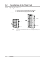
2.2
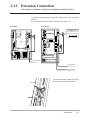
2.2.5
Installation of the Main Unit
Opening Front Cover
1. Loosen two screws on the right side of the main unit.
2. Open the front cover in the direction of arrow A .
KX-TD816
KX-TD1232
D1232
DIGITAL SUPE
R HYBRID SYST
EM
Screw
D816
DIGITAL SUPER
A
HYBRID SYSTE
M
Screw
A
Screw
Screw
Panaso
nic
Note
2-8
Installation
Panas
onic
Two screws are attached to the front cover with springs so that they will
not be lost.
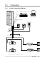
2.3
Connection
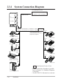
2.3.1
System Connection Diagram
D1232
DIGITAL SUPE
R HYBRID SYST
EM
Printer for SMDR or Personal Computer for System Programming
To AC Outlet
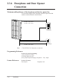
Doorphone
Door Opener 1
Door Opener 2
Panaso
nic
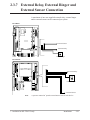
Central Ringer
External Sensor
External Relay
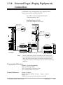
External Music Source 1
External Music Source 2
Amplifier
Speaker 1
Amplifier
Speaker 2
Note: The KX-TD1232 is illustrated as a main unit.
Installation
2-9
2.3.1 System Connection Diagram
(CO Lightning Protectors)
KX-TD816: to CO's 1 through 8
D1232
DEGITAL SUPER HYBRID SYSTEM
ISDN S0 Lines
KX-TD1232: to CO's 1 through 12
Panasonic
KX-TD816: 16 Extensions ( 8 extensions - initial, 8 extensions )
KX-TD1232:32 Extensions (16 extensions - initial, 16 extensions )
( one pair)
(two pair)
It is recommended that
extension of jack 1 is a display
proprietary telephone.
DI
GI
TA
L
Pana
soni
c
Single Line Telephone
( one pair)
KX-T7235
(two pair)
DIG
ITA
L
Pana
soni
c
Data Terminal
( one
pair)
KX-T7230
(two pair)
XXXXX
XXXXXXX
TALK
ON
OFF
F
DE
AB
C
2
JK
L
5
TU
V
8
3
1
MN
GH
I
4
S
7
6
O
DIGI
TAL
Pa
nas
oni
WX
PR
Y
Pana
soni
c
c
9
10CH
AUTO
DP
ER
SCAN
0
REDIAL/
PAUSE
XXXX
PROGRAM
X
XXXXXX
SOUND
XXXXXXX
CHARG
XXXX
XXXX
XXXXXXXXXXXXXXXXXX
TONE
AUTO
MUTE
ER
HOLD
MUTE
VOLUME
MIC
CH
CHARGE
XXXXXXX
nic
aso
10CH
Pan
XXXX
XXXXXXX
XXXX
PAGE/INT
ERCOM
Cordless Phone
( one pair)
KX-T7240
(two pair)
Panasonic
Telephone Answering
Machine with Facsimile
(one
pair)
Panasonic
XXXXXXXX
XXXXXXXX
XX
KX-T7250
: needs Optional Cards or Units.
Voice Processing System
2-10
Installation
• Parallel connection of telephone is possible.
Refer to Section 2.3.4 “Paralleled Telephone
Connection.”
• The KX-TD1232 is illustrated as a main unit.
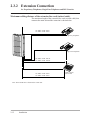
2.3.2 Extension Connection
for Proprietary Telephones, Single Line Telephones and DSS Consoles
To connect extension jacks, insert the connector(s) to the system as
shown.
For Cable Pin Numbers to Be Connected, see page 2-13.
KX-TD816
KX-TD1232
Connector type
50-pin (Amphenol 57 JE
series or the equivalent)
25
1
1
50
26
26
To extension
(Jack 1 - 8)
To extension
(Jack 9 - 16)
To extension
(Jack 1 - 8)
After inserting the connector, fasten
the connector with the nylon tie.
Installation
2-11
2.3.2 Extension Connection
for Proprietary Telephones, Single Line Telephones and DSS Consoles
Maximum cabling distance of the extension line cord (twisted cable)
The maximum length of the extension line cord (twisted cable) that
connects the main unit and the extension is shown below:
1232G
DIG
ITA
L
Pana
soni
c
24 AWG: Under 220 m
22 AWG: Under 360 m
D1232
DIGITAL SUPER
Proprietary Telephone
HYBRID SYSTE
M
Pa
na
so
nic
Single Line Telephone
Panaso
nic
24 AWG: Under 1100 m
22 AWG: Under 1800 m
DIGI
TAL
Pana
soni
c
24 AWG: Under 220 m
22 AWG: Under 360 m
Note: The KX-TD1232 is illustrated as a main unit.
2-12
Installation
DSS Console,
KX-T7240
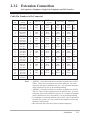
2.3.2 Extension Connection
for Proprietary Telephones, Single Line Telephones and DSS Consoles
Cable Pin Numbers to Be Connected
CONN.
PIN
26
1
27
2
29
4
30
5
32
7
33
8
35
10
36
11
38
13
39
14
41
16
42
17
44
19
45
20
47
22
48
23
50
25
CABLE
COLOR
WHT-BLU
BLU-WHT
WHT-ORN
ORN-WHT
WHT-BRN
BRN-WHT
WHT-SLT
SLT-WHT
RED-ORN
ORN-RED
RED-GRN
GRN-RED
RED-SLT
SLT-RED
BLK-BLU
BLU-BLK
BLK-GRN
GRN-BLK
BLK-BRN
BRN-BLK
YEL-BLU
BLU-YEL
YEL-ORN
ORN-YEL
YEL-BRN
BRN-YEL
YEL-SLT
SLT-YEL
VIO-ORN
ORN-VIO
VIO-GRN
GRN-VIO
VIO-SLT
SLT-VIO
Notes
CLIP
NO.
1
2
3
4
7
8
9
10
13
14
15
16
19
20
21
22
25
26
27
28
31
32
33
34
37
38
39
40
43
44
45
46
49
50
EXTN. 1-8
Jack
No.1
Jack
No.2
Jack
No.3
Jack
No.4
Jack
No.5
Jack
No.6
Jack
No.7
Jack
No.8
T
R
D1
D2
T
R
D1
D2
T
R
D1
D2
T
R
D1
D2
T
R
D1
D2
T
R
D1
D2
T
R
D1
D2
T
R
D1
D2
EXTN. 9-16
8EXTN†1
T
R
Jack
D1
No.9
D2
T
R
Jack
D1
No.10
D2
T
R
Jack
D1
No.11
D2
T
Jack
R
D1
No.12
D2
T
Jack
R
No.13
D1
D2
T
Jack
R
No.14
D1
D2
T
Jack
R
No.15
D1
D2
T
Jack
R
No.16
D1
D2
8EXTN†2
Jack
No.17
Jack
No.18
Jack
No.19
Jack
No.20
Jack
No.21
Jack
No.22
Jack
No.23
Jack
No.24
T
R
D1
D2
T
R
D1
D2
T
R
D1
D2
T
R
D1
D2
T
R
D1
D2
T
R
D1
D2
T
R
D1
D2
T
R
D1
D2
8EXTN†2
Jack
No.25
Jack
No.26
Jack
No.27
Jack
No.28
Jack
No.29
Jack
No.30
Jack
No.31
Jack
No.32
T
R
D1
D2
T
R
D1
D2
T
R
D1
D2
T
R
D1
D2
T
R
D1
D2
T
R
D1
D2
T
R
D1
D2
T
R
D1
D2
• “8EXTN†1” in the table indicates an extension expansion area for KXTD816. There are two expansion areas on the main unit. Up to one
station line unit can be installed to any area. It is required to designate
which is Station Line Unit by System Programming.
• “8EXTN†2” in the table indicates an extension expansion area for KXTD1232. There are three expansion areas on the main unit. Up to two
station line units can be installed to any area. It is required to designate
which is Station Line Unit 1 and which is 2 by System Programming.
• If a telephone or answering machine with an A-A1 relay is connected to
the main unit, set the A-A1 relay switch of the telephone or answering
machine to OFF position.
• Mis-connection may cause the system to operate improperly.
Installation
2-13
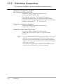
2.3.2 Extension Connection
for Proprietary Telephones, Single Line Telephones and DSS Consoles
Connection of a Proprietary Telephone,
KX-T7230, KX-T7235 or KX-T7250
4-conductor wiring is required for each extension.
Connect pins “D1” and “D2” only.
If the Method 2 in Section 2.3.4 “Paralleled Telephone
Connection,”and in Section 2.3.5 “EXtra Device Port (XDP)
Connection”is used for parallel connection of a PT and a standard
telephone, connect pins “T,” “R,” “D1” and “D2.”
Connection of a Single Line Telephone,
2-conductor wiring is required for each extension.
Connect pins “T” and “R.”
Connection of a DSS Console, KX-T7240
4-conductor wiring is required for each extension.
Connect pins “D1” and “D2” only. (“T” and “R” are not
necessary.)
Notes
2-14
Installation
• Up to four DSS Consoles can be installed for KX-TD816. Up to eight
DSS Consoles can be installed for KX-TD1232 per system. As the
DSS Console itself cannot work alone, it always requires a proprietary
telephone used in pair. Place the DSS Console and the paired telephone
side by side on your desk.
• It is necessary to designate the jack numbers of paired DSS Consoles
and the proprietary telephones by System Programming.
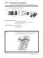
2.3.2 Extension Connection
for Proprietary Telephones, Single Line Telephones and DSS Consoles
Station Wiring (2-pair twisted cabling):
50 Pin Connector
26
Block Terminal
1
1
1
2
2
27
3
3
2
4
4
Green
Line cord
Red
DIG
ITA
L
Black
Pana
sonic
Yellow
Bridging Clips
Programming References
Section 4, System Programming,
[007] DSS Console Port and Paired Telephone Assignment
[109] Expansion Card/Unit Type
Feature References
Note
Section 3, Features,
DSS Console (KX-T7240)
Module Expansion
After completing all the required inside cabling, including ISDN S0
lines, extensions, external pagers, external music sources and so on,
fasten the cables with the nylon tie (included) as shown.
Installation
2-15
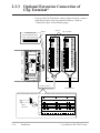
2.3.3 Optional Extension Connection of
Clip Terminal*
If you use the Clip Terminal to connect eight extensions, connect a
cable shown below to the clip terminal as follows. Refer to
“Connection Chart” on the following page.
Connector type
50-pin (amphenol 57JE
series or the equivalent)
25
1
50
26
Clip no.
Pin no.
IN
IN
Clip Terminal
20
20
40
40
19
19
39
39
18
18
38
38
17
17
37
37
16
16
36
36
15
15
35
35
14
14
34
34
13
13
33
33
12
12
32
32
11
11
31
31
10
10
30
30
9
9
29
29
8
8
28
28
7
7
27
27
6
6
26
26
5
5
25
25
4
4
24
24
3
3
23
23
2
2
22
22
1
1
21
21
OUT
IN
OUT
OUT
Cable (50 lines)
To Extensions
There are five kinds of dot for lines. You can distinguish a line by the number of dot and the color.
1:
2:
Cable
(50 lines)
3:
4:
C:
C: continuous
2-16
Installation
*: Available for KX-TD1232 only.
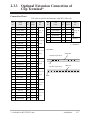
2.3.3 Optional Extension Connection of
Clip Terminal*
Connection Chart
This chart is used for the Panasonic cable KX-A204 only.
Pin
no.
Cable
Color
Pin
no.
Cable
Color
26
orange-red
1
1
T
47
yellow-red
43
C
T
1
orange-black
2
1
R 1, 9, 17
22
yellow-black
44
C
R 8, 16, 24
27
yellow-red
3
1
D1 or 25
48
green-red
45
C
D1 or 32
2
yellow-black
4
1
D2
23
green-black
46
C
D2
29
grey-red
7
1
T
50
white-red
49
C
4
grey-black
8
1
R 2, 10, 18
25
white-black
50
C
30
white-red
9
1
D1 or 26
5
white-black
10
1
D2
32
yellow-red
13
2
T
7
yellow-black
14
2
R 3, 11, 19
33
green-red
15
2
D1 or 27
Clip Number
no. of Dot
Jack
no.
8
green-black
16
2
D2
35
white-red
19
2
T
10
white-black
20
2
R 4, 12, 20
36
orange-red
21
3
D1 or 28
11
orange-black
22
3
D2
38
green-red
25
3
T
13
green-black
26
3
R 5, 13, 21
39
grey-red
27
3
D1 or 29
14
grey-black
28
3
D2
41
orange-red
31
4
T
16
orange-black
32
4
R 6, 14, 22
42
yellow-red
33
4
D1 or 30
17
yellow-black
34
4
D2
44
grey-red
37
4
T
19
grey-black
38
4
45
white-red
39
4
R 7, 15, 23
D1 or 31
20
white-black
40
4
D2
*: Available for KX-TD1232 only.
Clip Number
no. of Dot
Jack
no.
not use
C : continuous
EXAMPLE:
orange line
The line of pin no.26
red
The line of pin no.25
white line
black
Installation
2-17
2.3.4 Paralleled Telephone Connection
for a Proprietary Telephone and a Single Line Telephone
Any single line telephone can be connected in parallel with a
proprietary telephone as follows:
Method 1: Using a Modular T-Adaptor
D1232
DIGITAL SUPE
R HYBRID SYST
EM
Panas
onic
Modular T-Adaptor
(Panasonic KX-J66 or USOC RJA2X)
2-conductor wiring cord
Connect the pin number of “ T” and “R”.
4-conductor wiring cord
For PT: Connect the pin number of
“D1” and “D2”.
DIG
ITA
L
Pana
soni
c
Pa
na
so
Proprietary Telephone
(DPT=KX-T7230, KX-T7235,
KX-T7250)
Note: The KX-TD1232 is illustrated as a main unit.
2-18
Installation
Single Line Telephone
nic
2.3.4 Paralleled Telephone Connection
for a Proprietary Telephone and a Single Line Telephone
Method 2: Using a PT Jack
D1232
DIGITAL SUPER
HYBRID SYSTEM
Panaso
nic
2-conductor wiring cord
Connect the pin number of “T” and “R” .
4-conductor wiring cord
Connect the pin number of “T” , “R”, “D1” and
“D2”.
Rear of the telephone
DIG
ITA
L
Pana
sonic
Pa
na
so
nic
XXX
XX
Single Line Telephone
Notes
Feature References
Proprietary Telephone
(PT=KX-T7230, KX-T7235,
KX-T7250)
To main unit
(“TO EMSS” is
printed.)
TO EMSS
To single line
telephone (“TO
TEL” is printed.)
TO TEL
• Not only a single line telephone but a single line device such as an
answering machine, a facsimile or modem (personal computer) etc. can
be connected in parallel with a proprietary telephone.
• The KX-TD1232 is illustrated as a main unit.
Section 3, Features,
Paralleled Telephone
Installation
2-19
2.3.5 EXtra Device Port (XDP) Connection
for a Proprietary Telephone and a Single Line Telephone
A proprietary telephone (KX-T7230, KX-T7235 or KX-T7250) and
a single line telephone can be connected to the same extension jack
yet have different extension numbers (eXtra Device Port feature).
System Programming is required.
Method 1
D1232
DIGITAL SUPER
HYBRID SYSTE
M
Panaso
4-conductor wiring cord
Connect the pin number of “D1” and
“D2”.
nic
2-conductor wiring cord
Connect the pin number of “T” and
“R”.
DIG
ITA
L
Pana
sonic
Pa
na
so
Proprietary Telephone
(KX-T7230, KX-T7235, KX-T7250)
nic
Single Line Telephone
Method 2
Section 2.3.4 “Paralleled Telephone Connection, Method 2” is also
available for XDP connection.
Note
• The KX-TD1232 is illustrated as a main unit.
Programming References
Section 4, System Programming,
[600] EXtra Device Port
Feature References
2-20
Installation
Section 3, Features,
EXtra Device Port (XDP)
2.3.6 Doorphone and Door Opener
Connection
A maximum of one doorphone and two door openers can be
connected per system. They are user-supplied devices.
KX-TD816
Door opener 1
Doorphone
a b TO1 TO2 TS1 TS2
220V~
Doorphone adapter
KX-TD1232
~OV
L
O
U
B
~12V
~8V
To
L
O
U
B
CL
LG
Door opener 2
Door opener 1
Doorphone
a b TO1 TO2 TS1 TS2
LG: Light
CL: Call button
: Speaker
: Microphone
: Protect Cover
220V~
~OV
L
O
Doorphone adapter U
B
~12V
~8V
To
L
O
U
B
CL
LG
Door opener 2
Installation
2-21
2.3.6 Doorphone and Door Opener
Connection
Maximum cabling distance of the doorphone and the door opener line
The maximum length of the doorphone and door opener line that
connects to the main unit is shown below:
D1232
DIGITAL SUPE
R HYBRID SYST
24 AWG: Under 110 m
22 AWG: Under 180 m
EM
Doorphone
Panason
ic
Door opener
22 AWG: Under 180 m
Note
• The KX-TD1232 is illustrated as a main unit.
Programming References
Section 4, System Programming,
[122] Automatic Door Open
[511] Door Opener Access
[607]–[608] Doorphone Ringing Assignment — Day / Night
Feature References
2-22
Installation
Section 3, Features,
Door Opener
Doorphone Call
2.3.7 External Relay, External Ringer and
External Sensor Connection
A maximum of one user-supplied external relay, external ringer
and/or external sensor can be connected per system.
KX-TD816
External Sensor
External Relay
Central Ringer
KX-TD1232
External Relay
Central Ringer
External Sensor
Note
• System Connection* permits a maximum of two of each device.
*: Available for KX-TD1232 only.
Installation
2-23
2.3.7 External Relay, External Ringer and
External Sensor Connection
— External Relay
Programming References
Section 4, System Programming,
[213] External Relay Connecting Time
[512] External Relay Access
Feature References
Section 3, Features,
External Relay
— External Ringer
Programming References
Section 4, System Programming,
[418] External Ringer Assignment
[813] Floating Number Assignment
Feature References
Section 3, Features,
External Ringer
— External Sensor
Programming References
No programming required.
Feature References
2-24
Installation
Section 3, Features,
External Sensor
2.3.8 External Pager (Paging Equipment)
Connection
A maximum of two external pagers (user-supplied) can be
connected per system as illustrated below.
Use an RCA connector and shielded cable.
• Output impedance: 600 Ω
Maximum length of Cable
18-22 AWG, under 10 m (33 feet)
Pager jack 2
Pager jack 1
Pager jack 2
Pager jack 1
Speaker
Speaker
Amplifier
Amplifier
Paging equipment 2 Speaker
Amplifier
Paging equipment 2 Speaker
Amplifier
Paging equipment 1
KX-TD816
KX-TD1232
Notes
Paging equipment 1
• System Connection* permits a maximum of four external pagers.
• It is programmable that which external pager will send background
music and whether all the pagers will generate confirmation tone.
• To adjust the sound level of the pagers, use the volume control on the
amplifiers.
Programming References
Section 4, System Programming,
[804] External Pager BGM
[805] External Pager Confirmation Tone
[813] Floating Number Assignment
Feature References
Section 3, Features,
Background Music (BGM) – External Paging – External
Paging – All
Trunk (CO Line) Answer From Any Station (TAFAS)
*: Available for KX-TD1232 only.
Installation
2-25
2.3.9 External Music Source Connection
Up to two music sources such as a radio (user-supplied) can be
connected per system as illustrated below.
Insert the plug to the earphone / headphone jack on the
external music source.
Use a two-conductor plug {3.5 mm (9/64 inch) in diameter}.
• Input impedance: 8 Ω
Maximum length of Cable
18-22 AWG, under 10 m (33 feet)
KX-TD816
KX-TD1232
External Music Jack 2
External Music Jack 1
External Music Jack 2
External Music Jack 1
External Music Source 2
External Music Source 2
External Music Source 1
External Music Source 1
Notes
• System Programming of music sources used for Music on Hold and
Background Music is required.
• To adjust the sound level of the Music on Hold, use the volume control
on the external music source.
• The system is provided with an internal music source. By default
setting, internal music source is used as Music Source 1 for the systems.
System Programming is required to select internal music source.
Programming References
Section 4, System Programming,
[803] Music Source Use
[804] External Pager BGM
[990] System Additional Information, Field (20)
Feature References
2-26
Installation
Section 3, Features,
Background Music (BGM)
Music on Hold
Background Music (BGM) – External
2.3.10 Printer Connection
A user-supplied printer can be connected to the Serial Interface
(RS-232C) Connector on the main unit. The printer is used to print
out SMDR call records and system programming data.
Connect the Serial Interface (RS-232C) connector of the printer to
the Serial Interface Connector. Cables must be shielded and the
maximum length is 2 m (6.5 feet).
Serial Printer
Panaso
Serial Interface
(RS-232C)
nic
Note: The KX-TD1232 is illustrated as a main unit.
The pin configuration of Serial Interface (RS-232C) Connector is
as follows:
Pin
No.
Circuit Type
Signal Name
EIA
CCITT
1
2
FG
SD (TXD)
Frame Ground
Transmitted Data
AA
BA
101
103
3
4
RD (RXD)
RS (RTS)
Received Data
Request To Send
BB
CA
104
105
5
6
CS (CTS)
CR (DSR)
Clear To Send
Data Set Ready
CB
CC
106
107
7
8
SG
CD (DCD)
Signal Ground
Data Carrier Detect
AB
CF
102
109
20
ER (DTR)
Data Terminal
Ready
CD
108.2
Installation
2-27
2.3.10 Printer Connection
Connection Chart for Printer / Personal Computer (25-pin)
Serial Interface (RS-232C)
port on the main unit
Serial Interface (RS-232C)
port on the printer/PC
Circuit
Type
(EIA)
Signal
Name
Pin
No.
Pin
No.
Signal
Name
Circuit
Type
(EIA)
AA
BA
FG
SD (TXD)
1
2
1
3
FG
RD (RXD)
AA
BB
BB
CB
RD (RXD)
CS (CTS)
3
5
2
SD (TXD)
BA
CC
AB
CR (DSR)
SG
6
7
20
7
ER (DTR)
SG
CD
AB
CD
ER (DTR)
20
5
6
8
CS (CTS)
CR (DSR)
CD (DCD)
CB
CC
CF
Connection Chart for IBM Personal Computer (9-pin)
If you connect an IBM-PC to your system, see the chart below.
Serial Interface (RS-232C)
port on the main unit
2-28
Installation
Serial Interface (RS-232C)
port on the printer/IBM-PC
Circuit
Type
(EIA)
Signal
Name
Pin
No.
Pin
No.
Signal
Name
Circuit
Type
(EIA)
AA
BA
FG
SD (TXD)
1
2
2
RD (RXD)
BB
BB
RD (RXD)
3
3
SD (TXD)
BA
CB
CS (CTS)
5
5
6
SG
CR (DSR)
AB
CC
AB
CD
SG
ER (DTR)
7
20
7
RS (RTS)
CA
2.3.10 Printer Connection
Serial Interface (RS-232C) Signals
Frame Ground: FG
Connects to the unit frame and the earth ground conductor of the
AC power cord.
Transmitted Data: SD (TXD) ............................................(output)
Conveys signals from the unit to the printer. A “Mark” condition is
held unless data or BREAK signals are being transmitted.
Received Data: RD (RXD) .................................................(input)
Conveys signals from the printer.
Request to Send: RS (RTS)................................................(output)
This lead is held ON whenever CR (DSR) is ON.
Clear To Send: CS (CTS)...................................................(input)
An ON condition of circuit CS (CTS) indicates that the printer is
ready to receive data from the unit. The unit does not attempt to
transfer data or receive data when circuit CS (CTS) is OFF.
Data Set Ready: CR (DSR)................................................(input)
An ON condition of circuit CR (DSR) indicates the printer is ready.
Circuit CR (DSR) ON does not indicate that communication has
been established with the printer.
Signal Ground: SG
Connects to the DC ground of the unit for all interface signal.
Data Terminal Ready: ER (DTR) .....................................(output)
This signal line is turned ON by the unit to indicate that it is ON
LINE. Circuit ER (DTR) ON does not indicate that communication
has been established with the printer. It is switched OFF when the
unit is OFF LINE.
Data Carrier Detect: CD (DCD) .......................................(input)
The ON condition is an indication to data terminal (DTE) that the
carrier signal is being received.
Installation
2-29
2.3.10 Printer Connection
Programming References
Section 4, System Programming,
[800] SMDR Incoming / Outgoing Call Log Printout
[801] SMDR Format
[802] System Data Printout
[806]-[807] Serial Interface (RS-232C) Parameters – Port 1 / Port 2
Feature References
2-30
Installation
Section 3, Features,
Station Message Detail Recording (SMDR)
System Programming and Diagnosis with Personal Computer