1
Digital Super Hybrid System
Please read this manual before connecting the
Digital Super Hybrid System.
Attachment of customer owned equipment is illegal in
some areas of Canada.
Please consult with your Telephone Company.
D1232
DIGITAL SUPER
HYBRID SYSTE
M
D816
DIGITAL SUPER
HYBRID SYSTE
M
MODEL
KX-TD816/KX-TD816B
KX-TD1232/KX-TD1232B
KX-TD1232D/KX-TD1232DB
Panaso
nic
KX-TD816
Panaso
nic
KX-TD1232
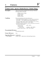
Thank you for purchasing the Panasonic Model
KX-TD816/KX-TD816B/KX-TD1232/KX-TD1232B/
KX-TD1232D/KX-TD1232DB, Digital Super Hybrid System.
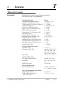
System Components
Service Unit
Telephone
Optional
Equipment
Model
KX-TD816/KX-TD816B
KX-TD1232/KX-TD1232B
KX-TD1232D/KX-TD1232DB
KX-T7220
KX-T7230
KX-T7235
KX-T7250
KX-T7130
KX-T7020
KX-T7030
KX-T7033
KX-T7050
KX-T7055
KX-T7051
KX-T7052
KX-T7240
KX-T7040
KX-TD160
KX-TD170/KX-TD170D
KX-TD180/KX-TD180D
KX-TD191*1
KX-TD192*1
KX-TD193*2
KX-TD196*1
KX-T30865
KX-T30890
KX-T7090
KX-A46
KX-A216*3
Description
Digital Super Hybrid System (Main Unit)
Digital Proprietary Telephone
Digital Proprietary Telephone with display
Digital Proprietary Telephone with large display
Digital Proprietary Telephone
Proprietary Telephone with display
Proprietary Telephone
Proprietary Telephone with display
Proprietary Telephone with display
Proprietary Telephone
Proprietary Telephone
Single Line Telephone
Single Line Telephone
Digital DSS Console
DSS Console
Doorphone Card
8-Station Line Unit
4-CO Line Unit
DISA Card
System Inter Connection Card (two cards with
Connection Cable)
Caller ID Card
Remote Card
Doorphone
Headset (Earphone type)
Headset (Headphone type)
Battery Adaptor
Backup Battery and Adaptor Card
System Components Table
The KX-TD816 and KX-TD816B are described as KX-TD816 in this Installation Manual
hereafter except necessary cases. Also, the KX-TD1232, KX-TD1232B, KX-TD1232D,
and KX-TD1232DB are described as KX-TD1232 except necessary cases.
The models marked *1 can be installed in KX-TD1232 only.
The model marked *2 can be installed in KX-TD816C/1232C and KX-TD816HK/1232HK only.
The model marked *3 can be installed in KX-TD816 only.
2
System Components
NOTES
• This Installation Manual does not show complete model numbers that indicate
the country where your models should be used. The model number of your
unit is found on the label affixed to the unit.
MODEL NO. – – – – – – – –
(label)
• The Digital Proprietary Telephone is abbreviated as “DPT.”
The Analog Proprietary Telephone is abbreviated as “APT.”
• Illustrations of DSHS and proprietary telephones used in this manual may be
different from the actual appearance of your DSHS and telephone models.
• Primary Power and default values of KX-TD1232DBX are the same as those
of the KX-TD1232BX in this manual. Similarly, KX-TD1232DXs’ are the
same as KX-TD1232Xs’.
• In this Installation Manual, the expansion unit KX-TD170D/KX-TD180D are
all described as KX-TD170/KX-TD180 except necessary cases.
• There are some features and models available for certain types of KX-TD816
or KX-TD1232 models. In that case, those manual describes each time what is
available for which model.
3
Precaution
• Keep the unit away from heating appliances and electrical noise generating devices
such as fluorescent lamps, motors and television. These noise sources can interfere
with the performance of the Digital Super Hybrid System.
• This unit should be kept free of dust, moisture, high temperature (more than 40˚C /
104˚F) and vibration, and should not be exposed to direct sunlight.
• Never attempt to insert wires, pins, etc. into the vents or other holes of this unit.
• If there is any trouble, disconnect the unit from the telephone line. Plug the
telephone directly into the telephone line. If the telephone operates properly, do not
reconnect the unit to the line until the trouble has been repaired. If the telephone
does not operate properly, chances are that the trouble is in the telephone system,
and not in the unit.
• Do not use benzine, thinner, or the like, or any abrasive powder to clean the
cabinet. Wipe it with a soft cloth.
WARNING
THIS UNIT MAY ONLY BE INSTALLED AND SERVICED BY QUALIFIED
SERVICE PERSONNEL.
WHEN A FAILURE OCCURS WHICH RESULTS IN THE INTERNAL PARTS
BECOMING ACCESIBLE, DISCONNECT THE POWER SUPPLY CORD
IMMEDIATELY AND RETURN THIS UNIT TO YOUR DEALER.
DISCONNECT THE TELECOM CONNECTION BEFORE DISCONNECTING
THE POWER CONNECTION PRIOR TO RELOCATING THE EQUIPMENT,
AND RECONNECT THE POWER FIRST.
THIS UNIT IS EQUIPPED WITH AN EARTHING CONTACT PLUG. FOR
SAFETY REASONS THIS PLUG MUST ONLY BE CONNECTED TO AN
EARTHING CONTACT SOCKET WHICH HAS BEEN INSTALLED
ACCORDING TO REGULATIONS.
THE POWER SOCKET WALL OUTLET SHOULD BE LOCATED NEAR THIS
EQUIPMENT AND BE EASILY ACCESSIBLE.
TO PREVENT FIRE OR SHOCK HAZARD, DO NOT EXPOSE THIS
PRODUCT TO RAIN OR MOISTURE.
The serial number of this product may be found on the label affixed to the
bottom of the unit. You should note the model number and the serial number of
this unit in the space provided and retain this book as a permanent record of your
purchase to aid in identification in the event of theft.
MODEL NO.:
SERIAL NO.:
4
Introduction
This Installation Manual provides technical information for the Panasonic Digital
Super Hybrid System, KX-TD816/KX-TD1232. It is designed to serve as an overall
technical reference for the system and includes a description of the system, its
hardware and software, features and services and environmental requirements.
This manual contains the following sections:
Section 1, System Outline.
Provides general information on the system including system capacity and
specifications.
Section 2, Installation.
Contains the basic system installation and wiring instructions, as well as how to
install the optional cards and units.
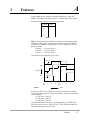
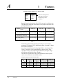
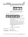
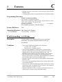
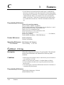
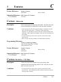
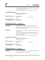
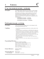
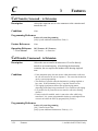
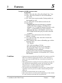
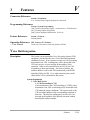
Section 3, Features.
Describes all the basic, optional and programmable features in alphabetical order. It
also provides information about the programming required, conditions, connection
references, related features and operation for every feature.
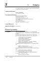
Section 4, System Programming.
Provides step-by-step programming instructions for a proprietary telephone.
Section 5, List.
Lists tone/ring tone and default values of system programming.
Section 6, Troubleshooting.
Provides information for system and telephone troubleshooting.
NOTE
The following documents may be used in conjunction with this manual:
• User Manual for KX-TD816/KX-TD1232 System, DIGITAL Proprietary Telephones,
DSS Console and Single Line Telephones.
• Programming Table
The programming table is designed to be used as a hard copy reference to the userprogrammed data.
5
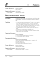
Information
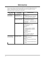
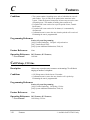
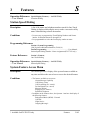
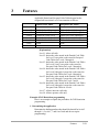
There are some features and items unavailable for certain KX-TD816/KX-TD1232
models. The table below shows what features/items are unavailable for which
models and in which sections they are described.
Model Number of
Main Unit
KX-TD816C
KX-TD1232C
KX-TD816NL
KX-TD1232NL
6
Unavailable
Feature/Item
Related Section
Panasonic Clip
Terminal, KX-A205
Section 2.3.4
“Optional Extension Connection
of KX-A205 (Clip Terminal)”
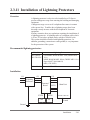
Panasonic Lightning
Protector, KX-A207
Section 2.3.11
“Installation of Lightning
Protectors” — Installation of the
KX-A207
Internal Music Source
Section 2.3.9
“External Music Source
Connection”
Section 3
“Background Music (BGM)”
“Background Music (BGM) –
External”
“Music on Hold”
Section 4.10
[990] “System Additional
Information”, Field (20)
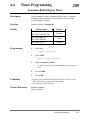
Automatic Redial
Section 3
“Redial, Automatic”
Section 4.4
[209] “Automatic Redial Repeat
Times”
[210] “Automatic Redial Interval
Time”
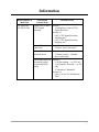
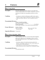
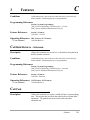
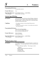
Information
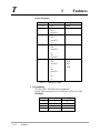
Model Number of
Main Unit
KX-TD816NL
KX-TD1232NL
Unavailable
Feature/Item
Related Section
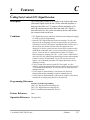
Calling Party Control
(CPC) Signal
Detection
Section 3
“Calling Party Control (CPC)
Signal Detection”
Section 4.6
[405] “CPC Signal Detection
Incoming Set”
[415] “CPC Signal Detection
Outgoing Set”
Pulse to Tone
Conversion
Section 3
“Pulse to Tone Conversion”
Handset/Headset
Volume Selector
Section 3
“Volume Control — Handset
Receiver/Headset”
Conversation between
two outside parties,
except using DISA
feature
Section 3
“Call Forwarding — to CO Line”
“Call Transfer, Screened — to CO
Line”
“Conference, Unattended”
Section 4.4
[206] “CO-to-CO Call Duration
Time”
7
Contents
Section 1, System Outline
1.1
1.2
1.3
1.4
*1
*1
*2
*1
*3
1.5
System Highlights .............................................................................
Basic System Construction ..............................................................
Proprietary Telephones ....................................................................
Options...............................................................................................
1.4.1 8-Station Line Unit (KX-TD170)............................................
1.4.2 4-CO Line Unit (KX-TD180) .................................................
1.4.3 System Inter Connection Card (KX-TD192) ..........................
1.4.4 DISA Card (KX-TD191).........................................................
1.4.5 Caller ID Card (KX-TD193) ...................................................
1.4.6 Remote Card (KX-TD196)......................................................
1.4.7 Doorphone Card (KX-TD160) ................................................
1.4.8 Backup Battery and Adaptor Card (KX-A216).......................
1.4.9 Battery Adaptor (KX-A46) .....................................................
1.4.10 DSS Console (KX-T7240 / KX-T7040)..................................
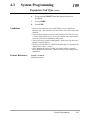
Specifications.....................................................................................
1.5.1 General Description.................................................................
1.5.2 Characteristics .........................................................................
1.5.3 System Capacity......................................................................
1-2
1-4
1-5
1-6
1-6
1-6
1-6
1-7
1-7
1-7
1-8
1-8
1-9
1-9
1-10
1-10
1-13
1-14
Section 2, Installation
2.1
2.2
2.3
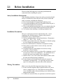
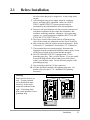
Before Installation ............................................................................
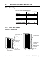
Installation of the Main Unit ...........................................................
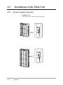
2.2.1 Unpacking ...............................................................................
2.2.2 Name and Location .................................................................
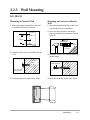
2.2.3 Wall Mounting.........................................................................
2.2.4 Frame Ground Connection ......................................................
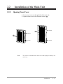
2.2.5 Opening Front Cover...............................................................
Connection.........................................................................................
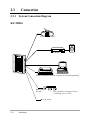
2.3.1 System Connection Diagram...................................................
2.3.2 CO Line Connection ...............................................................
2.3.3 Extension Connection
2-2
2-4
2-4
2-4
2-8
2-10
2-11
2-12
2-12
2-16
for Proprietary Telephones, Single Line Telephones and DSS Consoles..
2-19
2-28
2.3.4 Optional Extension Connection of KX-A205 (Clip Terminal) ...
2.3.5 Paralleled Telephone Connection
for a Proprietary Telephone and a Single Line Telephone ........................
2-30
2.3.6 EXtra Device Port (XDP) Connection
for a Digital Proprietary Telephone and a Single Line Telephone ............
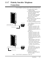
2.3.7 Polarity Sensitive Telephone Connection ...............................
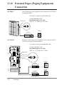
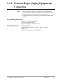
2.3.8 External Pager (Paging Equipment) Connection ....................
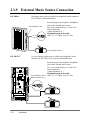
2.3.9 External Music Source Connection.........................................
8
2-32
2-33
2-34
2-36
*1 : Available for KX-TD1232 only.
*2 : Available for KX-TD816C/1232C and KX-TD816HK/1232HK only.
*3 : Available for KX-TD816 only.
Contents
2.4
*
*1
*2
1
*1
*3
2.5
2.6
2.7
2.8
2.3.10 Printer Connection...................................................................
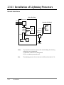
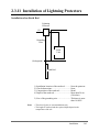
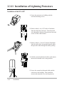
2.3.11 Installation of Lightning Protectors.........................................
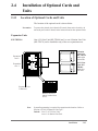
Installation of Optional Cards and Units .......................................
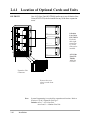
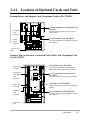
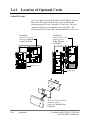
2.4.1 Location of Optional Cards and Units.....................................
2.4.2 4-CO Line Unit Connection ....................................................
2.4.3 8-Station Line Unit Connection ..............................................
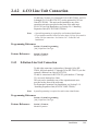
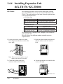
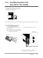
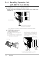
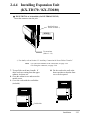
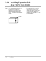
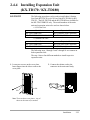
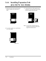
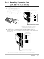
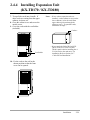
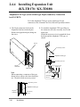
2.4.4 Installing Expansion Unit
(KX-TD170 / KX-TD180) ......................................................
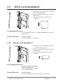
2.4.5 DISA Card Installation............................................................
2.4.6 Remote Card Installation.........................................................
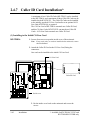
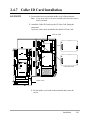
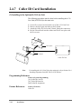
2.4.7 Caller ID Card Installation ......................................................
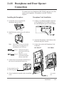
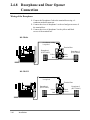
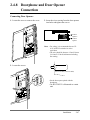
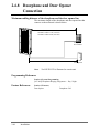
2.4.8 Doorphone and Door Opener Connection...............................
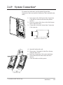
2.4.9 System Connection..................................................................
2.4.10 Backup Battery and Adaptor Card Connection.......................
2.4.11 Battery Adapter Connection....................................................
Auxiliary Connection for Power Failure Transfer ........................
Starting the System for the First Time ...........................................
System Restart ..................................................................................
System Data Clear ............................................................................
2-38
2-41
2-45
2-45
2-49
2-49
2-50
2-61
2-61
2-62
2-65
2-69
2-71
2-72
2-74
2-76
2-78
2-79
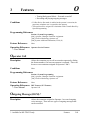
Section 3, Features
A
B
C
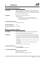
Absent Message Capability ................................................................
Account Code Entry ...........................................................................
Alternate Calling – Ring / Voice.........................................................
Answering, Direct CO Line................................................................
Automatic Callback Busy (Camp-On) ...............................................
Automatic Redial → Redial, Automatic.............................................
Automatic Route Selection (ARS) .....................................................
Automatic Station Release..................................................................
Background Music (BGM).................................................................
Background Music (BGM) – External ...............................................
Busy Lamp Field ................................................................................
Busy Station Signaling (BSS) ............................................................
Button, Direct Station Selection (DSS) .............................................
Button, Flexible ..................................................................................
Button, Group-CO (G-CO).................................................................
Button, Loop-CO (L-CO) ...................................................................
Button, Single-CO (S-CO) .................................................................
Buttons on Proprietary Telephones.....................................................
CALL FORWARDING FEATURES – SUMMARY .........................
Call Forwarding – All Calls ...............................................................
*1 : Available for KX-TD1232 only.
*2 : Available for KX-TD816C/1232C and KX-TD816HK/1232HK only.
*3 : Available for KX-TD816 only.
3-2
3-2
3-4
3-4
3-5
3-98
3-6
3-11
3-11
3-12
3-13
3-13
3-14
3-15
3-16
3-17
3-18
3-19
3-21
3-21
9
Contents
Call Forwarding – Busy......................................................................
Call Forwarding – Busy / No Answer ................................................
Call Forwarding – Follow Me ............................................................
Call Forwarding – No Answer............................................................
Call Forwarding – to CO Line............................................................
Call Hold – CO Line...........................................................................
Call Hold – Intercom ..........................................................................
Call Hold, Exclusive – CO Line.........................................................
Call Hold, Exclusive – Intercom ........................................................
Call Hold Retrieve – CO Line ............................................................
Call Hold Retrieve – Intercom............................................................
Call Park .............................................................................................
Call Pickup, CO Line .........................................................................
Call Pickup, Directed..........................................................................
Call Pickup, Group .............................................................................
Call Pickup Deny................................................................................
Call Splitting.......................................................................................
CALL TRANSFER FEATURES – SUMMARY ...............................
Call Transfer, Screened – to CO Line.................................................
Call Transfer, Screened – to Extension ..............................................
Call Transfer, Unscreened – to Extension ..........................................
Call Waiting ........................................................................................
1
* Caller ID .............................................................................................
Calling Party Control (CPC) Signal Detection...................................
Class of Service (COS).......................................................................
CO Line Connection Assignment.......................................................
CO Line Connection Assignment – Outgoing....................................
CO Line Group ...................................................................................
Conference..........................................................................................
Conference, Unattended .....................................................................
Confirmation Tone..............................................................................
Consultation Hold...............................................................................
D
Data Line Security ..............................................................................
Delayed Ringing → Ringing, Delayed...............................................
Dial Tone, Distinctive.........................................................................
Dial Type Selection ............................................................................
Direct In Lines (DIL)..........................................................................
*2 Direct Inward System Access (DISA)................................................
Direct Station Selection (DSS) Button → Button, Direct Station
Selection (DSS) .......................................................................
Directed Call Pickup → Call Pickup, Directed ..................................
10
3-22
3-23
3-24
3-24
3-25
3-26
3-27
3-27
3-28
3-28
3-29
3-29
3-30
3-31
3-31
3-32
3-32
3-33
3-33
3-34
3-34
3-35
3-36
3-37
3-38
3-39
3-39
3-40
3-41
3-41
3-42
3-44
3-45
3-101
3-45
3-46
3-48
3-48
3-14
3-31
*1 : Available for KX-TD816C/1232C and KX-TD816HK/1232HK only.
*2 : Available for KX-TD1232 only.
Contents
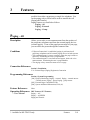
E
F
G
H
I
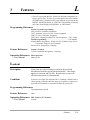
L
Display, Call Information ...................................................................
Display, Extension Programmed Data................................................
Display, Self-Extension Number ........................................................
Display, Time and Date ......................................................................
Display Contrast Adjustment .............................................................
Do Not Disturb (DND) .......................................................................
Do Not Disturb (DND) Override........................................................
Door Opener .......................................................................................
Doorphone Call ..................................................................................
DSS Console (KX-T7240 / KX-T7040).............................................
Electronic Station Lockout .................................................................
End-to-End DTMF Signaling (Tone Through)...................................
Exclusive Hold → Call Hold, Exclusive – CO Line / Intercom.........
Executive Busy Override – CO Line..................................................
Executive Busy Override – Extension................................................
Extension Group .................................................................................
External Feature Access .....................................................................
EXtra Device Port (XDP) ...................................................................
Flash....................................................................................................
Flexible Button → Button, Flexible ...................................................
Flexible Numbering............................................................................
Floating Station ..................................................................................
Full One-Touch Dialing......................................................................
Group Call Pickup → Call Pickup, Group .........................................
Group CO (G-CO) Button → Button, Group-CO (G-CO).................
Handset / Headset Selection ...............................................................
Handsfree Answerback.......................................................................
Handsfree Operation...........................................................................
Hold Recall .........................................................................................
Host PBX Access ...............................................................................
Intercept Routing ................................................................................
Intercom Calling .................................................................................
Last Number Redial → Redial, Last Number ....................................
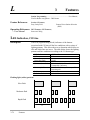
LED Indication, CO Line ...................................................................
LED Indication, Intercom...................................................................
Limited Call Duration.........................................................................
Line Access, Automatic......................................................................
Line Access, CO Line Group .............................................................
Line Access, Direct.............................................................................
Line Access, Individual ......................................................................
Line Preference – Incoming (No Line / Prime Line / Ringing Line) .
Line Preference – Outgoing (Idle Line / No Line / Prime Line) ........
3-52
3-53
3-54
3-54
3-55
3-55
3-56
3-56
3-57
3-58
3-60
3-61
3-27 / 28
3-61
3-62
3-63
3-63
3-64
3-65
3-15
3-65
3-68
3-69
3-31
3-16
3-69
3-70
3-70
3-71
3-72
3-72
3-73
3-99
3-74
3-75
3-76
3-76
3-77
3-78
3-79
3-79
3-80
11
Contents
Lockout...............................................................................................
Loop-CO (L-CO) Button → Button, Loop-CO (L-CO).....................
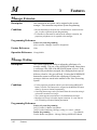
M Manager Extension .............................................................................
Message Waiting.................................................................................
Microphone Mute ...............................................................................
Mixed Station Capacities....................................................................
Module Expansion..............................................................................
Music on Hold ....................................................................................
N
Night Service ......................................................................................
O
Off-Hook Call Announcement (OHCA) ............................................
One-Touch Dialing .............................................................................
One-Touch Transfer by DSS Button...................................................
Operator ..............................................................................................
Operator Call ......................................................................................
1
* Outgoing Message (OGM) .................................................................
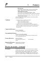
P
PAGING FEATURES – SUMMARY ................................................
Paging – All ........................................................................................
Paging – External ...............................................................................
Paging – Group...................................................................................
Paralleled Telephone...........................................................................
Pause Insertion, Automatic.................................................................
Pickup Dialing ....................................................................................
Power Failure Restart .........................................................................
Power Failure Transfer .......................................................................
Privacy, Automatic .............................................................................
Privacy Release...................................................................................
Pulse to Tone Conversion ...................................................................
R
Redial, Automatic ..............................................................................
Redial, Last Number ..........................................................................
Redial, Saved Number .......................................................................
Remote Station Lock Control .............................................................
*2 Reverse Circuit ...................................................................................
Ringing, Delayed ................................................................................
Ringing, Discriminating .....................................................................
Ringing Tone Selection for CO Buttons.............................................
S
Saved Number Redial → Redial, Saved Number...............................
Screened Call Transfer – to CO Line
→ Call Transfer, Screened – to CO Line ................................
Screened Call Transfer – to Extension
→ Call Transfer, Screened – to Extension ..............................
Secret Dialing .....................................................................................
12
3-81
3-17
3-82
3-82
3-83
3-83
3-84
3-85
3-85
3-86
3-87
3-88
3-88
3-89
3-89
3-90
3-91
3-92
3-93
3-93
3-94
3-95
3-96
3-96
3-97
3-97
3-98
3-98
3-99
3-100
3-100
3-101
3-101
3-102
3-102
3-100
3-33
3-34
3-103
*1 : Available for KX-TD1232 only.
*2 : Available for KX-TD816BX and KX-TD1232DBX/DX only.
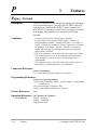
Contents
Single-CO (S-CO) Button → Button, Single-CO (S-CO) .................
Special Features for KX-T7235..........................................................
Call Log ........................................................................................................
Extension Dialing .........................................................................................
Station Speed Dialing ...................................................................................
System Feature Access Menu.......................................................................
System Speed Dialing...................................................................................
T
U
V
Station Feature Clear ..........................................................................
Station Hunting...................................................................................
Station Message Detail Recording (SMDR) .....................................
Station Programming..........................................................................
Station Programming Data Default Set ..............................................
Station Speed Dialing .........................................................................
*System Connection .............................................................................
System Data Default Set.....................................................................
System Programming and Diagnosis with Personal Computer..........
System Programming with Proprietary Telephone.............................
System Speed Dialing.........................................................................
Time-Out, Variable ............................................................................
Timed Reminder .................................................................................
Toll Restriction ...................................................................................
Toll Restriction for Special Carrier Access ........................................
Toll Restriction Override by Account Code Entry .............................
Toll Restriction Override for System Speed Dialing..........................
Trunk (CO Line) Answer From Any Station (TAFAS) .....................
Unattended Conference → Conference, Unattended .........................
Unscreened Call Transfer – to Extension
→ Call Transfer, Unscreened – to Extension ..........................
Voice Mail Integration ........................................................................
Volume Control – Speaker / Handset Receiver / Headset / Ringer ....
3-18
3-104
3-104
3-104
3-105
3-105
3-106
3-106
3-107
3-108
3-110
3-111
3-112
3-112
3-113
3-114
3-115
3-116
3-117
3-118
3-120
3-126
3-126
3-128
3-128
3-41
3-34
3-129
3-135
Section 4, System Programming
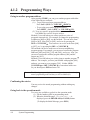
4.1
4.2
General Programming Instructions................................................
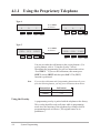
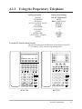
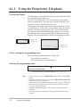
4.1.1 Using the Proprietary Telephone.............................................
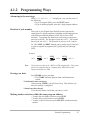
4.1.2 Programming Ways .................................................................
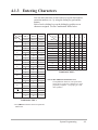
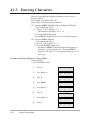
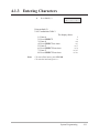
4.1.3 Entering Characters .................................................................
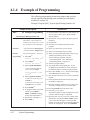
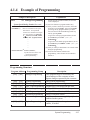
4.1.4 Example of Programming .......................................................
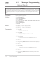
Manager Programming....................................................................
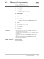
[000] Date and Time Set ...................................................................
[001] System Speed Dialing Number Set .........................................
[002] System Speed Dialing Name Set.............................................
* : Available for KX-TD1232 only.
4-2
4-3
4-7
4-9
4-12
4-14
4-14
4-16
4-18
13
Contents
4.3
*1
*1
4.4
*2
*2
*2
4.5
14
[003] Extension Number Set.............................................................
[004] Extension Name Set ................................................................
[005] Flexible CO Button Assignment .............................................
[006] Operator / Manager Extension Assignment ............................
[007] DSS Console Port and Paired Telephone Assignment ............
[008] Absent Messages .....................................................................
System Programming .......................................................................
[100] Flexible Numbering.................................................................
[101] Day / Night Service Switching Mode .....................................
[102] Day / Night Service Starting Time ..........................................
[103] Automatic Access CO Line Group Assignment ....................
[105] Account Codes ........................................................................
[106] Station Hunting Type ..............................................................
[107] System Password.....................................................................
[108] One-Touch Transfer by DSS Button .......................................
[109] Expansion Unit Type...............................................................
[110] Caller ID Code Set ..................................................................
[111] Caller ID Name Set ................................................................
[113] VM Status DTMF Set .............................................................
[114] VM Command DTMF Set.......................................................
[115] Adjust Time.............................................................................
[116] ROM Version Display .............................................................
Timer Programming.........................................................................
[200] Hold Recall Time ....................................................................
[201] Transfer Recall Time ...............................................................
[202] Call Forwarding – No Answer Time.......................................
[203] Intercept Time .........................................................................
[204] Pickup Dial Waiting Time .......................................................
[205] Extension-to-CO Line Call Duration Time .............................
[206] CO-to-CO Call Duration Time................................................
[207] First Digit Time .......................................................................
[208] Inter Digit Time.......................................................................
[209] Automatic Redial Repeat Times..............................................
[210] Automatic Redial Interval Time..............................................
[211] Dial Start Time ........................................................................
[212] Call Duration Count Start Time ..............................................
[213] DISA Delayed Answer Time ..................................................
[214] DISA Prolong Time.................................................................
[215] Outgoing Message Time .........................................................
TRS / ARS Programming ...............................................................
[300] TRS Override for System Speed Dialing ................................
4-19
4-21
4-23
4-25
4-26
4-28
4-29
4-29
4-32
4-33
4-35
4-36
4-37
4-38
4-39
4-40
4-42
4-43
4-44
4-46
4-48
4-49
4-50
4-50
4-51
4-52
4-53
4-54
4-55
4-56
4-57
4-58
4-59
4-60
4-61
4-62
4-63
4-64
4-65
4-66
4-66
*1 : Available for KX-TD816C/1232C and KX-TD816HK/1232HK only.
*2 : Available for KX-TD1232 only.
Contents
[301]–[305] TRS Denied Code Entry for Levels 2 through 6...........
[306]–[310] TRS Excepted Code Entry for Levels 2 through 6........
[311] Special Carrier Access Codes .................................................
[312] ARS Mode...............................................................................
[313] ARS Time................................................................................
[314]–[321] ARS Leading Digit Entry for Plans 1 through 8 ...........
[322]–[329] ARS Routing Plans 1 through 8 ....................................
[330] ARS Modify Removed Digit...................................................
[331] ARS Modify Added Number ..................................................
4.6 CO Line Programming ....................................................................
[400] CO Line Connection Assignment ...........................................
[401] CO Line Group Assignment....................................................
[402] Dial Mode Selection................................................................
[403] Pulse Speed Selection..............................................................
[404] DTMF Time ............................................................................
[405] CPC Signal Detection Incoming Set .......................................
*1 [406] Caller ID Assignment..............................................................
[407]–[408] DIL 1:1 Extension — Day / Night ................................
[409]–[410] Intercept Extension — Day / Night...............................
[411] Host PBX Access Codes .........................................................
[412] Pause Time ..............................................................................
[413] Flash Time...............................................................................
[414] Disconnect Time......................................................................
[415] CPC Signal Detection Outgoing Set .......................................
*2 [416] Reverse Circuit Assignment....................................................
4.7 COS Programming ...........................................................................
[500]–[501] Toll Restriction Level — Day / Night...........................
[502] Extension-to-CO Line Call Duration Limit ............................
[503] Call Transfer to CO Line.........................................................
[504] Call Forwarding to CO Line....................................................
[505] Executive Busy Override ........................................................
[506] Executive Busy Override Deny...............................................
[507] Do Not Disturb Override.........................................................
[508] Account Code Entry Mode......................................................
4.8 Extension Programming ..................................................................
[600] EXtra Device Port ...................................................................
[601] Class of Service.......................................................................
[602] Extension Group Assignment..................................................
[603]–[604] DIL 1:N Extension and Delayed Ringing
— Day / Night .........................................................................
[605]–[606] Outgoing Permitted CO Line Assignment
— Day / Night .........................................................................
*1 : Available for KX-TD816C/1232C and KX-TD816HK/1232HK only.
*2 : Available for KX-TD816BX and KX-TD1232DBX/DX only.
4-67
4-68
4-69
4-70
4-71
4-72
4-73
4-75
4-76
4-77
4-77
4-78
4-79
4-80
4-81
4-82
4-83
4-84
4-85
4-86
4-88
4-89
4-90
4-91
4-92
4-93
4-93
4-94
4-95
4-96
4-97
4-98
4-99
4-100
4-101
4-101
4-102
4-103
4-104
4-106
15
Contents
[607]–[608] Doorphone Ringing Assignment — Day / Night ..........
[609] Voice Mail Access Codes ........................................................
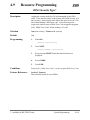
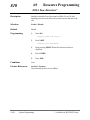
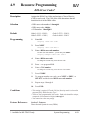
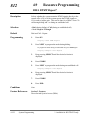
4.9 Resource Programming....................................................................
[800] SMDR Incoming / Outgoing Call Log Printout ......................
[801] SMDR Format .........................................................................
[802] System Data Printout...............................................................
[803] Music Source Use....................................................................
[804] External Pager BGM ...............................................................
[805] External Pager Confirmation Tone..........................................
[806]–[807] EIA (RS-232C) Parameters...........................................
*[809] DISA Security Type ................................................................
*[810] DISA Tone Detection ..............................................................
*[811] DISA User Codes ....................................................................
*[812] DISA DTMF Repeat ...............................................................
[813] Floating Number Assignment .................................................
*[814] Modem Standard .....................................................................
4.10 Option Programming .......................................................................
[990] System Additional Information...............................................
[991] COS Additional Information...................................................
[992] CO Line Group Additional Information..................................
4-108
4-110
4-111
4-111
4-112
4-113
4-114
4-115
4-116
4-117
4-119
4-120
4-121
4-122
4-123
4-125
4-126
4-126
4-131
4-133
Section 5, List
5.1
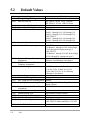
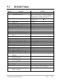
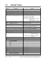
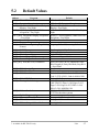
5.2
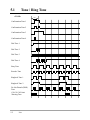
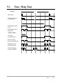
Tone / Ring Tone ...............................................................................
Default Values ...................................................................................
5-2
5-4
Section 6, Troubleshooting
6.1
16
Troubleshooting ................................................................................
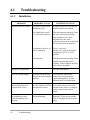
6.1.1 Installation...............................................................................
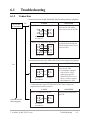
6.1.2 Connection ..............................................................................
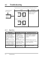
6.1.3 Operation.................................................................................
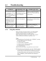
6.1.4 Using Reset Button..................................................................
6-2
6-2
6-3
6-4
6-5
* : Available for KX-TD1232 only.
Section 1
System Outline
This section provides general information on the system,
including system capacity and specifications.
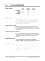
1.1
System Highlights
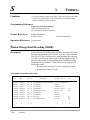
System Capacity
KX-TD816
CO line
Extension
KX-TD1232
CO line
Extension
Basic
System
Module
Expansion
System
Connection
4
8
8
16
—
—
8
16
12
32
24
64
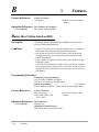
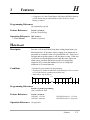
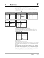
Module Expansion
Expansion modules are used to increase the system capacity. One
CO line module can be added to the basic system to add four CO
lines. For KX-TD816, one extension module can be added to the
basic system to add 8 extensions, and for KX-TD1232, two
extension modules to add 16 extensions.
EXtra Device Port (XDP)
Each extension jack in the system supports the connection of a
digital proprietary telephone and a single line device. The devices
have different extension numbers and are treated as two completely
different extensions.
Paralleled Telephone Connection
Every jack in the system also supports the parallel connection of a
proprietary telephone and a single line device. They share the same
extension number and are considered by the system to be one
extension.
Super Hybrid System
This system supports the connection of digital and analog
proprietary telephones, DSS Consoles and single line devices such
as single line telephones, facsimiles, and data terminals.
System Connection*
With the addition of optional System Inter Connection Card, two
Digital Super Hybrid Systems can be connected together to expand
the system to a maximum of 24 CO lines and 64 extensions. The
two systems function as one, however, some functions such as
paging and music on hold are duplicated.
1-2
System Outline
*: Available for KX-TD1232 only.
1.1
System Highlights
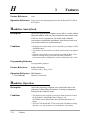
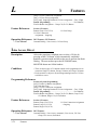
Digital Proprietary Telephones (DPT)
The system supports four different models of digital proprietary
telephones which cover the range from a monitor set to a large
display handsfree version.
Programming System
The system can be programmed from a proprietary telephone or
from a personal computer.
Voice Mail Integration
The system supports Voice Processing Systems with in-band
DTMF signaling. The Panasonic Voice Processing System
provides automated attendant, voice mail, interview and bulletin
board services.
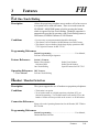
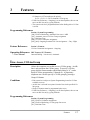
Automatic Route Selection (ARS)
Automatically selects the pre-programmed least expensive route for
outgoing toll calls.
Caller ID
Allows the user to see the name or telephone number of a caller on
the telephone display before answering the call. To use the features
of the Caller ID, you are required to subscribe to the Caller ID
(identification) service offered by your local telephone company for
a fee.
Trunk (CO Line) Answer From Any Station (TAFAS)
Ringing occurs over the external paging system; call can be
answered from any station.
Remote Station Lock Control
Allows an operator to lock an extension so that outgoing calls
cannot be made.
System Outline
1-3
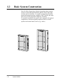
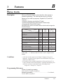
1.2
Basic System Construction
The KX-TD816 Digital Super Hybrid System has a basic capacity
of four CO lines and eight extensions, and KX-TD1232 has eight
CO lines and 16 extensions. It is capable of supporting Panasonic
digital and analog proprietary telephones, DSS Consoles and single
line devices such as single line telephones, facsimiles.
To expand its capabilities the system can be equipped with optional
components or customer-supplied peripherals such as external
speakers and external music sources (e.g., radios).
D1232
DIGITAL SUPE
R HYBRID SYST
EM
D816
DIGITAL SUPE
R HYBRID SYST
EM
Panaso
nic
1-4
System Outline
Panaso
nic
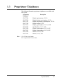
1.3
Proprietary Telephones
The following Panasonic proprietary telephones are available with
this system.
Proprietary
Telephone
KX-T7220
KX-T7230
KX-T7235
KX-T7250
KX-T7130
KX-T7020
KX-T7030
KX-T7033
KX-T7050
KX-T7055
Note :
Description
Digital, speakerphone, 24 CO
Digital, display, speakerphone, 24 CO
Digital, large display, speakerphone, 12 CO
Digital, monitor, 6 CO
Display, speakerphone, 12 CO, 12 PF
Speakerphone, 12 CO, 4 PF
Display, speakerphone, 12 CO, 4 PF
Display, speakerphone, 12 CO, 4 PF
Monitor, 12 CO, 4 PF
Monitor, 3 CO, 3 PF
CO: CO line access button
PF : Programmable Feature button
System Outline
1-5
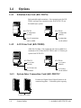
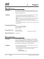
1.4
Options
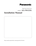
1.4.1
8-Station Line Unit (KX-TD170)
Each unit adds eight extensions. One expansion unit for KXTD816, and up to two expansion units for KX-TD1232 can
be installed per system.
D1232
DIGITAL SUPER HYBRID SYSTEM
D816
DIGITAL SUPER HYBRID SYSTEM
KX-TD1232
16 extensions
(initial)
Panasonic
Panasonic
8 or 16 extensions
can be added.
1.4.2
KX-TD816
8 extensions
(initial)
8 extensions
can be added.
4-CO Line Unit (KX-TD180)
Adds four CO lines. One expansion unit can be added for a
maximum of 8 CO lines for KX-TD816, and 12 CO lines per
system for KX-TD1232.
D1232
DIGITAL SUPER HYBRID SYSTEM
D816
DIGITAL SUPER HYBRID SYSTEM
Panasonic
KX-TD1232
8 CO lines
(initial)
Panasonic
4 CO lines can
be added.
1.4.3
KX-TD816
4 CO lines
(initial)
4 CO lines
can be added.
System Inter Connection Card (KX-TD192)*
D1232
DIGITAL SUPER
HYBRID SYSTEM
Panasonic
D1232
DIGITAL SUPER
HYBRID SYSTEM
Permits two Digital Super Hybrid Systems to be
connected together — to double system capacity.
Panasonic
Connection Cable
1-6
System Outline
*: Available for KX-TD1232 only.
1.4
1.4.4
D1232
DIGITAL SUPER
HYBRID SYSTEM
Panasonic
Options
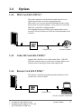
DISA Card (KX-TD191)*1
This card is required to use the Direct Inward System Access
(DISA) feature and to record an Outgoing Message.
DISA allows you to access the desired destination in the system
directly from an external telephone. Once you have accessed the
DISA line, just dial the extension number.
The Outgoing Messages (OGM) for the external callers can be
recorded, if necessary and/or an OGM for Timed Reminder can be
recorded.
Central
Office
Telephone Line
1.4.5
External Telephone
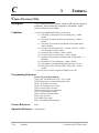
Caller ID Card (KX-TD193)*2
Supports the Caller ID service of the central office. Caller ID
allows the extension user to see the name or phone number of an
external caller on the display before answering the call.
1.4.6
D1232
DIGITAL SUPER
HYBRID SYSTEM
Panasonic
Remote Card (KX-TD196)*1
The Remote Card allows programming and maintenance of the
system from a remote location.
Central
Office
Telephone Line
Personal Computer with Modem
*1 : Available for KX-TD1232 only.
*2 : Available for KX-TD816C/1232C and
KX-TD816HK/1232HK only.
System Outline
1-7
1.4
1.4.7
Options
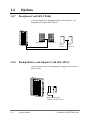
Doorphone Card (KX-TD160)
This card supports two doorphones and two door openers. The
doorphone is an option (KX-T30865).
D1232
DIGITAL SUPER
HYBRID SYSTEM
Panasonic
Doorphone 1
Doorphone 2
Door
Door
Opener
Opener 11
Panasonic
1.4.8
Panasonic
Door
Opener 2
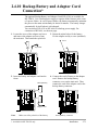
Backup Battery and Adaptor Card (KX-A216)*
Operate all the features as a backup power supply in the event of a
power failure.
D816
DIGITAL SUPE
R HYBRID SYSTE
M
Panas
onic
Backup Battery and
Adaptor Card (KX-A216)
1-8
System Outline
*: Available for KX-TD816 only.
1.4
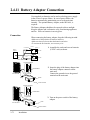
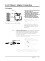
1.4.9
Options
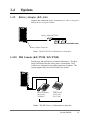
Battery Adaptor (KX-A46)
Supports the connection of two car batteries (12 VDC×2) for power
backup in case of a power failure.
D1232
DIGITAL SUPER
HYBRID SYSTEM
Battery
Adaptor
KX-A46
Battery
Adaptor
KX-A46
Panasonic
Two
Two car
car batteries,
batteries, connected
connected in
in series
series
Battery Adaptor Connector
Notes
The KX-TD1232 is illustrated as a main unit.
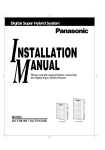
1.4.10 DSS Console (KX-T7240 / KX-T7040)
Permits easy and quick access to stations and features. The Busy
Lamp Field shows the idle or busy state of each station. DSS
Consoles are designed for use with a proprietary telephone. The
system supports up to four DSS Consoles per system.
D1232
DIGITAL SUPER
HYBRID SYSTEM
DIGI
TAL
Pana
soni
c
DIGIT
AL
Panaso
nic
Panasonic
Paired
PairedTelephone
Telephone
(Proprietary
(Proprietary
Telephone)
Telephone)
DSS
DSS Console
Console
KX-T7240/
KX-T7240/
KX-T7040
KX-T7040
Pair
Pair
Notes
The KX-TD1232 is illustrated as a main unit.
System Outline
1-9
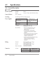
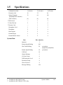
1.5
Specifications
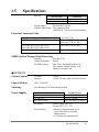
1.5.1 General Description
■ KX-TD816
System Capacity
CO lines
Stations
Control Method
CPU: 16-bit CPU
Switching
Non Blocking PCM Time Sharing Switch
Power Supplies
8 max.
16 max. (32 max. with eXtra Device Port)
Service Unit
KX-TD816BX
KX-TD816HK/ML/NL/NZ
KX-TD816C
Secondary
Station Supply Volt: 30V
Circuit Volt: ± 5V, ± 15V
• Memory backup duration: seven
years with a factory-provided
lithium battery
• 4 CO lines max. automatically
assigned to stations (Power Failure
Transfer)
• System operation for about 10 minutes
with optional Backup Battery and
Adaptor Card (KX-A216)
• System operation for about three hours
using recommended batteries
(consisting of two 12 VDC car
batteries)
Power Failure
Dialing
Outward
Internal
Mode Conversion
Connector
1-10
System Outline
CO lines
Primary Power
115 / 200 / 220 / 240 VAC,
50 / 60 Hz
220 – 240 VAC, 50 / 60 Hz
120 VAC, 60 Hz
Dial Pulse (DP) 10 pps, 20 pps
Tone (DTMF) Dialing
Dial Pulse (DP) 10 pps, 20 pps
Tone (DTMF) Dialing
DP-DTMF, DTMF-DP
Primary Power
Service Unit
4-pin
Connector
KX-TD816BX/HK/ML
Modular Jack (CA 14 A)
KX-TD816C/NL/NZ
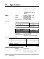
1.5
Specifications
Stations
Connector
Service Unit
KX-TD816BX/HK/ML 4-pin Connector
Modular Jack
KX-TD816C/NL/NZ
Paging Output
Pin Jack (RCA JACK)
External Music Input Two-conductors Jack
{MINIJACK 3.5 mm (9/64 inch) diameter}
Extension Connection Cable
Single line telephones, KX-T7051, KX-T7052 1 pair wire (T, R)
KX-T7220, KX-T7230, KX-T7235, KX-T7250 2 pair wire (D1, D2) or
2 pair wire (T, R, D1, D2)
2 pair wire (T, R, D1, D2)
KX-T7020, KX-T7030, KX-T7033,
KX-T7050, KX-T7055, KX-T7130
KX-T7240, KX-T7040
2 pair wire (D1, D2)
SMDR (Station Message Detail Recording)
Interface
Output Equipment
Detail Recording
EIA (RS-232C)
Printer
Date, Time, Extension Number, CO
Line Number, Dialed Number, Call
Duration, Account Code
System Capacity
CO lines
Stations
12 max.
32 max. (64 max. with eXtra Device Port)
Control Method
CPU: 16-bit CPU
Switching
Non Blocking PCM Time Sharing Switch
■ KX-TD1232
Power Supplies
Service Unit
KX-TD1232(D)BX/HK/ML/NL/NZ
KX-TD1232C
KX-TD1232(D)X
Secondary
Power Failure
Primary Power
220 – 240 VAC, 50 / 60 Hz
120 VAC, 60 Hz
110 – 120 VAC, 50 / 60 Hz
Station Supply Volt: 30V
Circuit Volt: ± 5V, ± 15V
• Memory backup duration: seven
years with a factory-provided
lithium battery
• 6 CO lines max. automatically
System Outline
1-11
1.5
Specifications
assigned to stations (Power Failure
Transfer)
• System operation for about three
hours using recommended batteries
(consisting of two 12 VDC car
batteries)
Dialing
Outward
Internal
Mode Conversion
Connector
Dial Pulse (DP) 10 pps, 20 pps
Tone (DTMF) Dialing
Dial Pulse (DP) 10 pps, 20 pps
Tone (DTMF) Dialing
DP-DTMF, DTMF-DP
CO lines
Service Unit
Connector
KX-TD1232DBX/DX
4-pin Connector
KX-TD1232BX/C/HK/ML/NL/NZ/X Modular Jack (CA 14A
for KX-TD1232C)
Stations
Connector
Service Unit
6-pin Connector
KX-TD1232DBX/DX
KX-TD1232BX/C/HK/ML/NL/NZ/X Amphenol Connector
Paging Output
Pin Jack (RCA JACK)
External Music Input Two-conductors Jack
(MINIJACK 3.5 mm 9/64 inch diameter}
Extension Connection Cable
Single line telephones, KX-T7051, KX-T7052 1 pair wire (T, R)
KX-T7220, KX-T7230, KX-T7235, KX-T7250 2 pair wire (D1, D2) or
2 pair wire (T, R, D1, D2)
2 pair wire (T, R, D1, D2)
KX-T7020, KX-T7030, KX-T7033,
KX-T7050, KX-T7055
3 pair wire (T, R, D1, D2, P1, P2)
KX-T7130
2 pair wire (D1, D2)
KX-T7240, KX-T7040
SMDR (Station Message Detail Recording)
Interface
Output Equipment
Detail Recording
1-12
System Outline
EIA (RS-232C)
Printer
Date, Time, Extension Number, CO
Line Number, Dialed Number, Call
Duration, Account Code
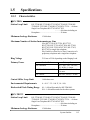
1.5
1.5.2
Specifications
Characteristics
■ KX-TD816
Station Loop Limit
KX-T7220/KX-T7230/KX-T7235/KX-T7250/KX-T7020/KXT7030/KX-T7033/KX-T7050/KX-T7055/KX-T7130 .....40 ohms
Single Line Telephone/KX-T7051/KX-T7052
.............600 ohms including set
Doorphone................................................20 ohms
Minimum Leakage Resistance
15 000 ohms
Maximum Number of Station Instruments per Line
1 for KX-T7220, KX-T7230, KX-T7235,
KX-T7250, KX-T7130, KX-T7020, KX-T7030,
KX-T7033, KX-T7050, KX-T7055, KX-T7051,
KX-T7052 or single line telephone
2 by Parallel or eXtra Device Port Connection of a
proprietary telephone and a single line telephone
Ring Voltage
70 Vrms at 25 Hz depending on the Ringing Load
Primary Power
Service Unit
KX-TD816BX
KX-TD816HK/ML/NL/NZ
KX-TD816C
Primary Power
115 / 200 / 220 / 240 VAC,
50 / 60 Hz, 1 A max.
220 – 240 VAC, 50 / 60 Hz,
1 A max.
120 VAC, 60 Hz, 1 A max.
Central Office Loop Limit
1 600 ohms max.
Environmental Requirements
0 – 40 °C / 32 – 104 °F, 10 – 90%
Hookswitch Flash Timing Range
84 – 1 000 milliseconds for KX-TD816NL
204 – 1 000 milliseconds for the other systems
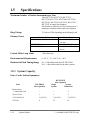
■ KX-TD1232
Station Loop Limit
KX-T7220/KX-T7230/KX-T7235/KX-T7250/KX-T7020/KXT7030/KX-T7033/KX-T7050/KX-T7055/KX-T7130 .....40 ohms
Single Line Telephone/KX-T7051/KX-T7052
.............600 ohms including set
Doorphone................................................20 ohms
Minimum Leakage Resistance
15 000 ohms
System Outline
1-13
1.5
Specifications
Maximum Number of Station Instruments per Line
1 for KX-T7220, KX-T7230, KX-T7235,
KX-T7250, KX-T7130, KX-T7020, KX-T7030,
KX-T7030, KX-T7050, KX-T7055, KX-T7051,
KX-T7052 or single line telephone
2 by Parallel or eXtra Device Port Connection of a
proprietary telephone and a single line telephone
Ring Voltage
Primary Power
70 Vrms at 25 Hz depending on the Ringing Load
Service Unit
KX-TD1232(D)BX/HK/ML/NL/NZ
KX-TD1232C
KX-TD1232(D)X
Primary Power
220 – 240 VAC, 50 / 60 Hz,
1.4 A max.
120 VAC, 60 Hz, 2 A max.
110 – 120 VAC, 50 / 60 Hz,
2 A max.
Central Office Loop Limit
1 600 ohms max.
Environmental Requirements
0 – 40 °C / 32 – 104 °F, 10 – 90%
Hookswitch Flash Timing Range
84 – 1 000 milliseconds for KX-TD1232NL
204 – 1 000 milliseconds for the other systems
1.5.3 System Capacity
Lines, Cards, Station Equipment
Item
*System Inter
Connection Card
KX-TD816
Max. Quantity
KX-TD1232
Max. Quantity
Single
System
System
Connection
—
—
2
Service Unit
1
1
2
4-CO Line Unit
1 (4 CO's)
1 (4 CO’s)
2 (8 CO’s)
CO Line
8
12
24
1-14
System Outline
*: Available for KX-TD1232 only.
1.5
Specifications
8-Station Line Unit
1 (8 extn.)
2 (16 extn.)
4 (32 extn.)
Extension Jack
16
32
64
Station Terminal
(including DSS Consoles)
32
64
128
{DSS Console}
{4}
{4}
{8}
*1 DISA Card
—
1
2
*2 Caller ID Card
2
3
6
*1 Remote Card
—
1
2
Doorphone Card
1
1
2
Doorphone
2
2
4
Door Opener
2
2
4
External Pager
1
2
4
External Music Source
1
2
4
System Data
Item
Max. Quantity
Operator
2
System Speed Dialing
100
One-Touch Dialing
24
per station
(proprietary telephone)
Station Speed Dialing
10
per station
Call Park
10
Absent Message
9
CO Line Group
8
Toll Restriction Level
8
Extension Group
8
Class of Service
8
Message Waiting
128
*1 : Available for KX-TD1232 only.
*2 : Available for KX-TD816C/1232C only.
System Outline
1-15
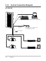
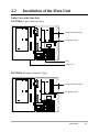
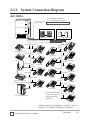
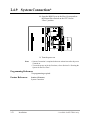
2.3.1 System Connection Diagram
KX-TD1232
D1232
DIGITAL SUPE
R HYBRID SYST
EM
Printer for SMDR or Personal Computer for System Programming
Battery Adaptor
KX-A46
Panaso
nic
Two car batteries, connected in series
• Consisting of two 12 VDC
To AC Outlet
External Music Source 1
External Music Source 2
2-14
Installation
Amplifier
Speaker
Amplifier
Speaker
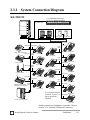
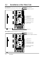
2.3.1 System Connection Diagram
KX-TD1232
D1232
DEGITAL SUPER HYBRID SYSTEM
(CO Lightning Protectors)
to CO’s 1 through 8 (initial)
to CO’s 9 through 12 (additional)
12 CO Lines
Doorphone KX-T30865
Panasonic
Panasonic
Doorphone 1
Panasonic
Doorphone 2
Door Opener 1 Door Opener 2
32 Extensions (16 extensions - initial, 16 extensions- additional)
(two pair)
DIGI
TAL
Panaso
nic
(one pair) (one pair)
(two
pair)
(two pair) KX-T7235
Single Line Telephone
(one pair) (one
pair)
KX-T7051
DIGITAL
Panasonic
KX-T7220
Panasonic
(two
pair)
Data Terminal
(one pair) (two
pair)
XXX
XXXXXXXXX
TALK
F
D E
C
A B
2
L
J K
5
O
M N
6
Y
W X
V
T U
KX-T7250
Pan
aso
nic
9
(two pair)
8
7
10CH
AUTO
SCAN
0
E R
D P
REDIAL/
PAUSE
XXXX
PROGRAM
XXXXXXX
SOUND
MUTE
XXXXXXXXX
XXXX
XXXXXXXXXXXXXXXXXX
TONE
AUTO
2
1
3
CH
LOW
10CH
4
5
6
7
8
O
AUT
Pana
sonic
3
4
S
P R
KX-T7230
DIGI
TAL
KX-T7052
ON
OFF
1
I
G H
(two pair)
9
FULL
CHARGE
XX
10
N
SCA
nic
aso
Pan
R
HOLD
MUTE
VOLUME
MIC
CHARGE
XXXXXXXXX
XX
XXXXXXXXX
XX
PAGE/INTE
RCOM
KX-T7240
Cordless Phone
(two pair)
(one pair)
KX-T7050
KX-T7130
(two pair)
(two
pair)
(one
Telephone Answering pair)
KX-T7030
(two pair)
Machine with Facsimile
Panasonic
XXXXXXXXX
XXXXXXXXX
KX-T7055
Voice Processing System
KX-T7033
It is recommended that
extension of jack 1 is a
display proprietary
telephone.
KX-T7020
(two pair)
KX-T7040
Parallel connection of telephones is possible. Refer to
Section 2.3.4 “Paralleled Telephone Connection.”
: needs Optional Cards or Adaptor.
Installation
2-15
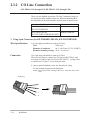
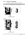
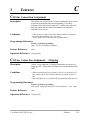
2.3.2 CO Line Connection
(KX-TD816: CO1 through CO4, KX-TD1232: CO1 through CO8)
There are two methods to perform CO Line Connection, using a 4pin connector and a modular connector. Which method should be
used depends on the model number of the system as shown below.
Model number
Connector to be used
KX-TD816BX/HK/ML
4-pin Connector
KX-TD1232DBX/DX
KX-TD816C/NL/NZ
Modular Connector
KX-TD1232BX/C/HK/ML/NL/NZ/X
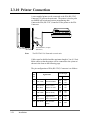
1. Using 4-pin Connector (for KX-TD816BX./HK/ML, KX-TD1232BX/DX)
Wire Specifications
Use 4-pin plugs (included) to connect CO lines.
Wire
Solid wire
Diameter of conductor
ø0.4 – ø0.65 mm (22, 24, 26AWG)
Diameter including coating ø0.66 – ø1.05 mm
Connection
Use 4-pin plugs (included) to connect CO lines.
There are two plugs to connect four CO lines for KX-TD816, and
four plugs to connect eight CO lines for KX-TD1232. A plug is able
to connect two CO lines. Use twisted pair cable.
1. Insert required telephone wires into the holes in a plug.
Fix the transparent part into the black part.
Notes: Do not peel off the coating of the wires. Insert the wires to the
ends.
4-pin plug
T
R
T
R
2-16
Installation
2.3.2 CO Line Connection
(KX-TD816: CO1 through CO4, KX-TD1232: CO1 through CO8)
2. Insert the plug into an CO jack in the main unit.
KX-TD816
CO 4
CO 3
T
R
T
R
CO 2
CO 1
To Terminal Board or Modular
Jacks from the Central Office
KX-TD1232
REMOTE
CO 8
SYSTEM INTER
CONNECTION
CO 7
CO 6
CO 5
CO 4
DISA
CO 3
DOORPHONE
T
R
T
R
CO 2
CO 1
To Terminal Board or Modular
Jacks from the Central Office
Installation
2-17
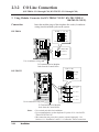
2.3.2 CO Line Connection
(KX-TD816: CO1 through CO4, KX-TD1232: CO1 through CO8)
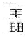
2. Using Modular Connector (for KX-TD816C/NL/NZ, KX-TD1232BX/C/
HK/ML/NL/NZ/X)
Connection
Insert the modular plugs of the telephone line cords (4-conductor
wiring) into the modular jacks on the system.
R: Ring @ @ T: Tip
KX-TD816
T2
R1
T1
R2
View of TEL Jack (CO)
(T1, R1)(T2, R2)
CO 3, CO 4
CO 1, CO 2
Use 4-conductor wiring cord
To Terminal Board or Modular
Jacks from the Central Office.
T2 R1 T1 R2
KX-TD1232
R: Ring
T: Tip
REMOTE
SYSTEM INTER
CONNECTION
View of TEL Jack (CO)
(T1, R1) (T2, R2)
DISA
DOORPHONE
CO 7, CO 8
CO 5, CO 6
CO 3, CO 4
CO 1, CO 2
Use 4-conductor wiring cord
To Terminal Board or Modular
Jacks from the Central Office.
Notice
2-18
Installation
• Use twisted pair cable for installation.
• It is recommended to use the telephone CO jacks of CA 14A for KXTD816C/KX-TD1232C.
• Mis-connection may cause the system to operate improperly. See
Section 6.1.1 “Installation” and 6.1.2 “Connection” before connection.
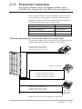
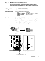
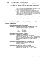
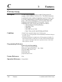
2.3.3 Extension Connection
for Proprietary Telephones, Single Line Telephones and DSS Consoles
(KX-TD816: Jack 1 through Jack 8, KX-TD1232: Jack 1 through Jack 16)
There are four methods to perform Extension Connection, using a
4-pin connector, a 6-pin connector, a modular connector and an
Amphenol Connector. Which method should be used depends on
the model number of the system as shown below.
Model number
KX-TD816BX/HK/ML
KX-TD1232DBX/DX
KX-TD816C/NL/NZ
KX-TD1232BX/C/HK/ML/NL/NZ/X
Connector to be used
4-pin Connector
6-pin Connector
Modular Connector
Amphenol Connector
Maximum cabling distance of the extension line cord (twisted cable)
The maximum length of the extension line cord (twisted cable) that
connects the main unit and the extension is shown below:
DI
26 AWG; Under 140 m (460 feet)
24 AWG; Under 229 m (750 feet)
22 AWG; Under 360 m (1180 feet)
GI
TA
L
Pana
soni
c
D1232
DIGITAL SUPE
R HYBRID SYSTE
M
Proprietary Telephone
Single Line Telephone
26 AWG; Under 698 m (2290 feet)
24 AWG; Under 1128 m (3700 feet)
22 AWG; Under 1798 m (5900 feet)
DIG
ITAL
Pan
ason
ic
26 AWG; Under 140 m (460 feet)
24 AWG; Under 229 m (750 feet)
22 AWG; Under 360 m (1180 feet)
DSS Console
(KX-T7240,
KX-T7040)
Notes The KX-TD1232 is illustrated as a main unit.
Installation
2-19
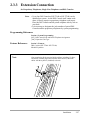
2.3.3 Extension Connection
for Proprietary Telephones, Single Line Telephones and DSS Consoles
(KX-TD816: Jack 1 through Jack 8, KX-TD1232: Jack 1 through Jack 16)
1. Using 4-pin Connector (for KX-D816BX/HK/ML)
Connection
Use 4-pin plugs (included) to connect extensions.
There are 8 plugs to connect extensions to jacks 1 through 8.
1. Insert required telephone wires into the holes in a plug. Fix the
transparent part into the black part.
Notes : Do not peel off the coating of the wires.
Insert the wires to the ends.
4-pin plug
DI
T
R
D2
2. Insert the plug into an extension jack in the main unit.
Jack 4
Jack 3
Jack 2
Jack 1
D1
T
R
D2
Jacks 1 through 8 are
located from bottom to top.
To extensions
(Jacks 1 – 8)
2-20
Installation
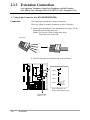
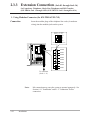
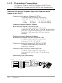
2.3.3 Extension Connection
for Proprietary Telephones, Single Line Telephones and DSS Consoles
(KX-TD816: Jack 1 through Jack 8, KX-TD1232: Jack 1 through Jack 16)
2. Using 6-pin Connector (for KX-TD1232DBX/DX)
Wire Specification
The wire specifications are as follows:
Wire
Solid wire
Diameter of conductor ø0.4-ø0.65 mm (22, 24, 26AWG)
Diameter including
ø0.66-ø1.05 mm
Coating
Connection
Use 6-pin plugs (included) to connect extensions.
There are 16 plugs to connect extensions to jacks 1 through 16.
1. Insert required telephone wires into the holes in a plug. Fix the
transparent part into the black part.
Notes : Do not peel off the coating of the wires.
Insert the wires to the ends.
6-pin plug
P2
D1
T
R
D2
P1
2. Insert the plug into an extension jack in the main unit.
REMOTE
Jack 4
SYSTEM INTER
CONNECTION
Jack 3
Jack 2
DISA
DOORPHONE
P2
D1
T
R
D2
P1
Jack 1
Jacks 1 through 16 are
located from bottom to top.
To extensions (Jacks 1 – 16)
Installation
2-21
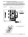
2.3.3 Extension Connection (Jack 01 through Jack 16)
for Proprietary Telephones, Single Line Telephones and DSS Consoles
(KX-TD816: Jack 1 through Jack 8, KX-TD1232: Jack 1 through Jack 16)
1. Using Modular Connector (for KX-TD816C/NL/NZ)
Connection
Insert the modular plugs of the telephone line cords (4-conductor
wiring) into the modular jacks on the system.
D1: Data 1 D2: Data 2
R: Ring @ T: Tip
D2
R
T
D1
View of TEL Jack (Extension)
Jack 8
Jack 7
Jack 6
Jack 5
Jack 4
Jack 3
Jack 2
Jack 1
To extensions
(Jacks 1 – 8)
Notes:
2-22
Installation
Mis-connection may cause the system to operate improperly. See
Section 6.1.1 "Installation" and 6.1.2 "Connection" before
connection.
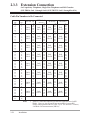
2.3.3 Extension Connection (Jack 01 through Jack 16)
for Proprietary Telephones, Single Line Telephones and DSS Consoles
(KX-TD816: Jack 1 through Jack 8, KX-TD1232: Jack 1 through Jack 16)
2. Using Amphenol Connector (for KX-TD1232BX/C/HK/ML/NL/NZ/X)
Connection
To connect jacks 1 through 16, insert the connectors to the system
as shown.
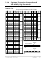
For Cable Pin Numbers to Be Connected, see page 2-24.
REMOTE
SYSTEM INTER
CONNECTION
Connector type
Connector
type
50-pin(Amphenol
(Amphenol 57JE
50-pin
57 JE
series
the equivalent)
series
ororthe
equivalent)
25
1
50
26
DISA
DOORPHONE
To extensions
16)
To extensions
(Jacks
9–
(Jacks
9-16)
To
Toextensions
extensions
(Jacks 1-8)
(Jacks 1 – 8)
After inserting the connector, fasten
the connector with the nylon tie.
Installation
2-23
2.3.3 Extension Connection
for Proprietary Telephones, Single Line Telephones and DSS Consoles
(KX-TD816: Jack 1 through Jack 8, KX-TD1232: Jack 1 through Jack 16)
Cable Pin Numbers to Be Connected
CONN.
PIN
26
1
27
2
28
3
29
4
30
5
31
6
32
7
33
8
34
9
35
10
36
11
37
12
38
13
39
14
40
15
41
16
42
17
43
18
44
19
45
20
46
21
47
22
48
23
49
24
50
25
CLIP
NO.
1
2
3
4
5
6
7
8
9
10
11
12
13
14
15
16
17
18
19
20
21
22
23
24
25
26
27
28
29
30
31
32
33
34
35
36
37
38
39
40
41
42
43
44
45
46
47
48
49
50
EXTN. 1-8
Jack
No.1
Jack
No.2
Jack
No.3
Jack
No.4
Jack
No.5
Jack
No.6
Jack
No.7
Jack
No.8
Notes
2-24
Installation
T
R
D1
D2
P1
P2
T
R
D1
D2
P1
P2
T
R
D1
D2
P1
P2
T
R
D1
D2
P1
P2
T
R
D1
D2
P1
P2
T
R
D1
D2
P1
P2
T
R
D1
D2
P1
P2
T
R
D1
D2
P1
P2
EXTN. 9-16
8EXTN† 1
T
R
D1
Jack
D2
No.9
P1
P2
T
R
D1
Jack
No.10 D2
P1
P2
T
R
D1
Jack
No.11 D2
P1
P2
T
R
D1
Jack
No.12 D2
P1
P2
T
R
D1
Jack
No.13 D2
P1
P2
T
R
D1
Jack
No.14 D2
P1
P2
T
R
D1
Jack
No.15 D2
P1
P2
T
R
D1
Jack
No.16 D2
P1
P2
8EXTN†2
8EXTN† 2
T
R
D1
D2
P1
P2
T
R
D1
D2
P1
P2
T
R
D1
D2
P1
P2
T
R
D1
D2
P1
P2
T
R
D1
D2
P1
P2
T
R
D1
D2
P1
P2
T
R
D1
D2
P1
P2
T
R
D1
D2
P1
P2
T
R
D1
D2
P1
P2
T
R
D1
D2
P1
P2
T
R
D1
D2
P1
P2
T
R
D1
D2
P1
P2
T
R
D1
D2
P1
P2
T
R
D1
D2
P1
P2
T
R
D1
D2
P1
P2
T
R
D1
D2
P1
P2
Jack
No.17
Jack
No.18
Jack
No.19
Jack
No.20
Jack
No.21
Jack
No.22
Jack
No.23
Jack
No.24
Jack
No.25
Jack
No.26
Jack
No.27
Jack
No.28
Jack
No.29
Jack
No.30
Jack
No.31
Jack
No.32
†1 “8EXTN” in the table indicates an extension expansion area for KXTD816. However, pins P1 and P2 are not available, because KXTD816 cannot perform OHCA by KX-T7130. See Section 3. Features,
“Off-Hook Call Announcement (OHCA)”.
2.3.3 Extension Connection
for Proprietary Telephones, Single Line Telephones and DSS Consoles
(KX-TD816: Jack 1 through Jack 8, KX-TD1232: Jack 1 through Jack 16)
There are two expansion areas on the main unit of KX-TD816, one for
8-Station Line Unit and the other for 4-CO Line Unit.
† 2 “8EXTN” in the table indicates an extension expansion area for KXTD1232. There are three expansion areas on the main unit of KXTD1232. Up to two 8-Station Line Units and a 4-CO Line Unit can be
installed to any area. It is required to designate which is 8-Station Line
Unit 1 and which is 2 by system programming.
• If a telephone or answering machine with an A-A1 relay is connected to
the main unit, set the A-A1 relay switch of the telephone or answering
machine to OFF position.
• Mis-connection may cause the system to operate improperly. See
Section 6.1.1 “Installation” and 6.1.2 “Connection.”
Connection of Proprietary Telephones, Single Line Telephones and DSS
Consoles for KX-TD816
Connection of an Analog Proprietary Telephone,
KX-T7020, KX-T7030, KX-T7033, KX-T7050, KX-T7055 or KX-T7130
4-conductor wiring is required for each extension.
Connect pins “T”, “R”, “D1” and “D2”.
T: Tip
D1: Data 1
R: Ring
D2: Data 2
Connection of a Digital Proprietary Telephone,
KX-T7220, KX-T7230, KX-T7235, or KX-T7250
4-conductor wiring is required for each extension.
Connect pins “D1” and “D2” only. (“T” and “R” are only needed if
Section 2.3.4 “Paralleled Telephone Connection,” Method 2 is used
for parallel or XDP connection of a DPT and a single line
telephone.)
Connection of a Single Line Telephone, KX-T7051 or KX-T7052
2-conductor wiring is required for each extension.
Connect pins “T” and “R”.
Connection of a DSS Console, KX-T7040 or KX-T7240
4-conductor wiring is required for each extension.
Connect pins “D1” and “D2” only. (“T” and “R” are not
necessary.)
Installation
2-25
2.3.3 Extension Connection
for Proprietary Telephones, Single Line Telephones and DSS Consoles
(KX-TD816: Jack 1 through Jack 8, KX-TD1232: Jack 1 through Jack 16)
Connection of Proprietary Telephones, Single Line Telephones and DSS
Consoles for KX-TD1232
Connection of the Proprietary Telephone, KX-T7130
6-conductor wiring is required for each extension.
Connect pins “T”, “R”, “D1”, “D2”, “P1” and “P2”.
T: Tip
D1: Data 1
P1: 3 Pair Voice (OHCA)
R: Ring
D2: Data 2
P2: 3 Pair Voice (OHCA)
Connection of a Digital Proprietary Telephone,
KX-T7220, KX-T7230, KX-T7235, or KX-T7250
4-conductor wiring is required for each extension.
Connect pins “D1” and “D2” only. (“T” and “R” are only needed if
Section 2.3.4 “Paralleled Telephone Connection,” Method 2 is used
for parallel or XDP connection of a DPT and a single line
telephone.)
Connection of an Analog Proprietary Telephone,
KX-T7020, KX-T7030, KX-T7033, KX-T7050 or KX-T7055
4-conductor wiring is required for each extension.
Connect pins “T”, “R”, “D1” and “D2”.
Connection of a Single Line Telephone, KX-T7051 or KX-T7052
2-conductor wiring is required for each extension.
Connect pins “T” and “R”.
Connection of a DSS Console, KX-T7040 or KX-T7240
4-conductor wiring is required for each extension.
Connect pins “D1” and “D2” only. (“T” and “R” are not
necessary.)
Station Wiring (3-pair twisted cabling):
Block Terminal
50-Pin Connector
26
1
1
1
2
2
27
3
3
2
4
4
28
5
5
3
6
6
Bridging Clips
2-26
Installation
Green
Red
Black
Yellow
White
Blue
Line cord
6
5
4
3
2
1
2.3.3 Extension Connection
for Proprietary Telephones, Single Line Telephones and DSS Consoles
Notes
• Up to four DSS Consoles (KX-T7040 or KX-T7240) can be
installed per system. As the DSS Console itself cannot work
alone, it always requires a proprietary telephone used in pair.
Place the DSS Console and the paired telephone side by side on
your desk.
• It is necessary to designate the jack numbers of paired DSS
Consoles and the proprietary telephones by system programming.
Programming References
Section 4, System Programming,
[007] DSS Console Port and Paired Telephone Assignment
[109] Expansion Unit Type
Feature References
Note
Section 3, Features,
DSS Console (KX-T7240 / KX-T7040)
Module Expansion
After completing all the required inside cabling, including CO lines,
extensions, external pagers and external music sources, fasten the
cables with the nylon tie (included) as shown.
Installation
2-27
2.3.4 Optional Extension Connection of
KX-A205 (Clip Terminal)*
If you use the Clip Terminal, KX-A205 to connect eight extensions,
connect a cable shown below to the clip terminal as follows. Refer
to “Connection Chart” on the following page.
Clip no.
Connector type
50-pin (Amphenol 57JE
series or the equivalent)
Pin no.
25
1
50
26
KX-A205 (Clip Terminal)
REMOTE
SYSTEM INTER
CONNECTION
DISA
IN
20
20
40
40
19
19
39
39
18
18
38
38
17
17
37
37
16
16
36
36
15
15
35
35
14
14
34
34
13
13
33
33
12
12
32
32
11
11
31
31
10
10
30
30
9
9
29
29
8
8
28
28
7
7
27
27
6
6
26
26
5
5
25
25
4
4
24
24
3
3
23
23
2
2
22
22
1
1
21
21
OUT
IN
OUT
DOORPHONE
IN
OUT
Cable (50 lines)
To Extensions
There are five kinds of dot for lines. You can distinguish a line by the number of dot and the color.
1:
2:
Cable
(50 lines)
3:
4:
C:
C: continuous
2-28
Installation
*: Available for KX-TD1232 only.
2.3.4 Optional Extension Connection of
KX-A205 (Clip Terminal)*
Connection Chart
This chart is used for the Panasonic cable KX-A204 only.
Pin
no.
Cable
Color
Pin
no.
Cable
Color
26
orange-red
1
1
T
41
orange-red
31
4
T
1
orange-black
2
1
R
16
orange-black
32
4
R
27
yellow-red
3
1
D1 1, 9, 17
42
yellow-red
33
4
D1 6, 14, 22
2
yellow-black
4
1
D2 or 25
17
yellow-black
34
4
D2 or 30
28
green-red
5
1
P1
43
green-red
35
4
P1
3
green-black
6
1
P2
18
green-black
36
4
P2
29
grey-red
7
1
T
44
grey-red
37
4
T
4
grey-black
8
1
R
19
grey-black
38
4
R
30
white-red
9
1
D1 2, 10, 18
45
white-red
39
4
D1 7, 15, 23
5
white-black
10
1
D2 or 26
20
white-black
40
4
D2 or 31
31
orange-red
11
2
P1
46
orange-red
41
C
P1
6
orange-black
12
2
P2
21
orange-black
42
C
P2
32
yellow-red
13
2
T
47
yellow-red
43
C
T
7
yellow-black
14
2
R
22
yellow-black
44
C
R
33
green-red
15
2
D1 3, 11, 19
48
green-red
45
C
D1 8, 16, 24
8
green-black
16
2
D2 or 27
23
green-black
46
C
D2 or 32
34
grey-red
17
2
P1
49
grey-red
47
C
P1
9
grey-black
18
2
P2
24
grey-black
48
C
P2
35
white-red
19
2
T
50
white-red
49
C
10
white-black
20
2
R
25
white-black
50
C
36
orange-red
21
3
D1 4, 12, 20
11
orange-black
22
3
D2 or 28
37
yellow-red
23
3
P1
12
yellow-black
24
3
P2
38
green-red
25
3
T
13
green-black
26
3
R
39
grey-red
27
3
D1 5, 13, 21
Clip Number
no. of Dot
Jack
no.
14
grey-black
28
3
D2 or 29
40
white-red
29
3
P1
15
white-black
30
3
P2
Clip Number
no. of Dot
Jack
no.
not use
C : continuous
EXAMPLE:
orange line
The line of pin no.26
red
The line of pin no.25
white line
black
*: Available for KX-TD1232 only.
Installation
2-29
2.3.5 Paralleled Telephone Connection
for a Proprietary Telephone and a Single Line Telephone
Any single line telephone can be connected in parallel with a
proprietary telephone as follows:
Method 1: Using a Modular T-Adaptor
D1232
DIGITAL SUPER
HYBRID SYSTE
M
Modular T-Adaptor
(Panasonic KX-J66 or USOC RJA2X)
2-conductor wiring cord
Connect pins “T” and “R”.
4-conductor wiring cord
For DPT: Connect pins “D1” and “D2”
only. (“T” and “R” are not necessary.)
For APT: Connect pins “T”, “R”, “D1”
and “D2”.
Digital Proprietary Telephone
(DPT=KX-T7220, KX-T7230,
KX-T7235, KX-T7250),
Analog Proprietary Telephone
(APT=KX-T7020, KX-T7030,
KX-T7033, KX-T7050, KXT7055, KX-T7130)
Notes
2-30
Installation
Single Line Telephone,
KX-T7051 or KX-T7052
• The KX-TD1232 is illustrated as a main unit.
• The 6-conductor wiring cord (and the Modular T-Adaptor KX-J36) is
required if the proprietary telephone KX-T7130 is to be used for
parallel connection for KX-TD1232.
2.3.5 Paralleled Telephone Connection
for a Proprietary Telephone and a Single Line Telephone
Method 2: for Digital Proprietary Telephone only
D1232
DIGITAL SUPER
HYBRID SYSTEM
4-conductor wiring cord
Connect pins “T”, “R”, “D1”
and “D2”.
2-conductor wiring cord
Connect pins “T” and “R”.
Rear of the telephone
To main unit
(“TO EMSS”
is printed)
Digital Proprietary
Telephone (KX-T7220,
KX-T7230, KX-T7235,
KX-T7250)
Single Line
Telephone,
KX-T7051 or
KX-T7052
Notes
Feature References
To Single Line
Telephone (“TO
TEL” is printed)
LCD ADJ
PUSH
TO EMSS
TO TEL
• The KX-TD1232 is illustrated as a main unit.
• Not only a single line telephone but a single line device such as an
answering machine, a facsimile or a modem (personal computer) etc.
can be connected in parallel with a proprietary telephone.
Section 3, Features,
Paralleled Telephone
Installation
2-31
2.3.6 EXtra Device Port (XDP) Connection
for a Digital Proprietary Telephone and a Single Line Telephone
A digital proprietary telephone (KX-T7220, KX-T7230, KXT7235, or KX-T7250) and a single line telephone can be connected
to the same extension jack yet have different extension numbers
(eXtra Device Port feature). System Programming is required for
this jack.
Method 1
D1232
DIGITAL SUPER
HYBRID SYSTEM
4-conductor wiring cord
Connect pins “D1” and “D2”
only. (“T” and “R” are not
necessary.)
2-conductor wiring cord
Connect pins “T” and “R”.
Digital Proprietary
Telephone (KX-T7220, KX-T7230,
KX-T7235, KX-T7250)
Notes
Single Line Telephone,
KX-T7051 or KX-T7052
The KX-TD1232 is illustrated as a main unit.
Method 2
Section 2.3.5 “Paralleled Telephone Connection, Method 2: for
Digital Proprietary Telephone only” is also available for XDP
connection.
Programming References
Section 4, System Programming,
[600] EXtra Device Port
Feature References
2-32
Installation
Section 3, Features,
EXtra Device Port (XDP)
2.3.7 Polarity Sensitive Telephone
Connection
If your telephone is polarity sensitive, follow the procedures below:
D1232
DIGITAL SUPER
HYBRID SYSTEM
Extension
Central Office Line
2
3
4
5
6
7
8
9
1
0
Reverse here
D1232
DIGITAL SUPER
HYBRID SYSTEM
Extension
Central Office Line
1
2
3
4
5
6
7
8
9
0
Reverse here
Notes
1. Complete all the required
extension wirings.
2. Confirm that dialing can be done
from all the extensions using a
touch-tone telephone.
If you fail to do that, the polarity
between the extension and the
system must be reversed.
3. Reverse as shown.
4. Set the Power Switch on the main
unit to “OFF” position.
5. Connect all CO lines.
6. Confirm that dialing can be done
on the following extensions using
a tone telephone.
• KX-TD816
Extension (T, R) of jack 1•••CO 1
Extension (T, R) of jack 2•••CO 2
Extension (T, R) of jack 9 and 10
(Extension Expansion Card)•••CO 5
and CO 6
• KX-TD1232
Extension (T, R) of jack 1•••CO 1
Extension (T, R) of jack 2•••CO 2
Extension (T, R) of jack 9•••CO 3
Extension (T, R) of jack 10•••CO 4
Extensions (T, R) of jacks 17 and 18
(Extension Expansion Card 1)•••CO
9 and CO 10
(Note: Extensions of jacks 9 and
10 for KX-TD816, and 17 and 18
for KX-TD1232 depend on the
Power Failure Transfer connection.
For details, refer to Section 2.5
“Auxiliary Connection for Power
Failure Transfer.”)
If you fail to do that, the polarity
between the system and the CO
line must be reversed.
7. Reverse as shown.
8. Every time an extension
telephone is replaced, repeat the
above procedures.
The KX-TD1232 is illustrated as a main unit.
Installation
2-33
2.3.8 External Pager (Paging Equipment)
Connection
KX-TD816
One external pager (user-supplied) can be connected to KX-TD816
as illustrated below.
Use an RCA connector and shielded cable.
D816
• Output impedance: 600 Ω
Maximum length of the cable
AWG 18 – 22: Under 10 m (33 feet)
Paging Jack
DIGITAL SUPE
R HYBRID SYST
EM
Speaker
Amplifier
Panason
ic
Paging Equipment
KX-TD1232
Up to two external pagers (user-supplied) can be connected to KXTD1232 per system as illustrated below.
Use an RCA connector and shielded cable.
• Output impedance: 600 Ω
Maximum length of the cable
AWG 18 – 22: Under 10 m (33 feet)
REMOTE
SYSTEM INTER
CONNECTION
Paging Jack 2
Paging Jack 1
DISA
Speaker
DOORPHONE
Amplifier
Paging Equipment 2
Speaker
Amplifier
Paging Equipment 1
2-34
Installation
2.3.8 External Pager (Paging Equipment)
Connection
Notes
• System Connection* permits a maximum of four external pagers.
It is programmable which external pager will send background music
and whether all the pagers will generate confirmation tone.
• To adjust the sound level of the pagers, use the volume control on the
amplifiers.
Programming References
Section 4, System Programming,
[804] External Pager BGM
[805] External Pager Confirmation Tone
Feature References
Section 3, Features,
Background Music (BGM) – External Paging – External
Paging – All
Trunk (CO Line) Answer From Any Station
*: Available for KX-TD1232 only.
Installation
2-35
2.3.9 External Music Source Connection
KX-TD816
One music source such as a radio (user-supplied) can be connected
to KX-TD816 as illustrated below.
Insert the plug to the earphone / headphone
jack on the external music source.
Use a two-conductor plug {3.5 mm (9/64
inch) in diameter}.
• Input impedance: 8 Ω
Maximum length of the cable
AWG 18 – 22: Under 10 m (33 feet)
External Music Jack
D816
DIGITAL SUPE
R HYBRID SYST
EM
Panaso
nic
External Music Source
KX-TD1232
REMOTE
SYSTEM INTER
CONNECTION
Up to two music sources such as a radio (user-supplied) can be
connected to KX-TD1232 per system as illustrated below.
Insert the plug to the earphone / headphone
jack on the external music source.
Use a two-conductor plug {3.5 mm (9/64
inch) in diameter}.
• Input impedance: 8 Ω
Maximum length of the cable
External Music Jack 2 AWG 18 – 22: Under 10 m (33 feet)
External Music Jack 1
DISA
DOORPHONE
External Music Source 2
External Music Source 1
2-36
Installation
2.3.9 External Music Source Connection
Notes
• System Programming of music sources used for Music on Hold and
Background Music is required.
• To adjust the sound level of the Music on Hold, use the volume control
on the external music source.
• The KX-TD816BX and KX-TD1232(D)BX/HK/ML/NL/NZ/(D)X
systems are provided with an internal music source. By default setting,
an internal music source is used as Music Source 1 for the systems.
System Programming is required to select external music source for the
systems.
Programming References
Section 4, System Programming,
[803] Music Source Use
[990] System Additional Information, Field (20)
Feature References
Section 3, Features,
Background Music (BGM)
Music on Hold
Background Music (BGM) – External
Installation
2-37
Section 2
Installation
This section contains the basic system installation and wiring
instructions, as well as how to install the optional cards and
units.
2.1
Before Installation
Please read the following notes concerning installation and
connection before installing the system.
Safety Installation Instructions
When installing telephone wiring, basic safety precautions should
always be followed to reduce the risk of fire, electric shock and
injury to persons, including the following:
1. Never install telephone wiring during a lightning storm.
2. Never install telephone jacks in wet locations unless the jack is
specifically designed for wet locations.
3. Never touch uninsulated telephone wires or terminals unless the
telephone line has been disconnected at the network interface.
4. Use caution when installing or modifying telephone lines.
Installation Precautions
This set is exclusively made for wall mounting only. Avoid
installing in the following places. (Doing so may result in
malfunction, noise, or discoloration.)
1. In direct sunlight and hot, cold, or humid places. (Temperature
range: 0°C – 40°C / 32°F – 104°F)
2. Sulfuric gases produced in areas where there are thermal springs,
etc. may damage the equipment or contacts.
3. Places in which shocks or vibrations are frequent or strong.
4. Dusty places, or places where water or oil may come into
contact with the unit.
5. Near high-frequency generating devices such as sewing
machines or electric welders.
6. On or near computers, telexes, or other office equipment, as well
as microwave ovens or air conditioners. (It is preferable not to
install in the same room with the above equipment.)
7. Install at least 1.8 m (6 feet) from radios and televisions. (both
the main unit and proprietary telephones)
8. Do not obstruct area around the main unit (for reasons of
maintenance and inspection — be especially careful to allow
space for cooling above and at the sides of the main unit).
Wiring Precautions
Make sure to keep the following instructions when wiring.
1. Do not wire the telephone cable in parallel with an AC power
source, computer, telex, etc. If the cables are run near those
wires, shield the cables with metal tubing or use shielded cables
and ground the shields.
2. If cables are run on the floor, use protectors or the like to protect
2-2
Installation
2.1
Before Installation
3.
4.
5.
6.
7.
8.
9.
10.
the wires where they may be stepped on. Avoid wiring under
carpets.
Avoid using the same power supply outlet for computers,
telexes, and other office equipment. Otherwise, the KXTD816’s and KX-TD1232’s system operation may be
interrupted by the induction noise from such equipment.
Please use one pair telephone wire for extension connection of
(telephone) equipment such as single line telephones, data
terminals, answering machines, computers, voice processing
systems, etc., except proprietary telephones (KX-T7220, KXT7230, KX-T7235, KX-T7250 etc.).
The Power Switch of the system must be off during wiring.
After all the wirings are completed, turn the Power Switch on.
Mis-wiring may cause the system to operate improperly. Refer
to Section 6.1.1 “Installation” and Section 6.1.2 “Connection.”
If an extension does not operate properly, disconnect the
telephone from the extension line and then connect again, or turn
off the Power Switch of the system and then on again.
The KX-TD816/KX-TD1232 is equipped with a 3-wire
grounding type plug. This is a safety feature. If you are unable
to insert the plug into the outlet, contact your electrician to
replace your obsolete outlet. Do not defeat the purpose of the
grounding-type plug.
Use twisted pair cable for CO line connection.
CO lines should be installed with lightning protectors. For
details, refer to Section 2.3.11 “Installation of Lightning
Protectors.”
Warning:
Static sensitive devices are
used. To protect printed
circuit boards from static
electricity, do not touch
connectors indicated to the
right. To discharge body
static, touch ground or wear a
grounding strap.
Warning : Static sensitive connectors
REMOTE
SYSTEM INTER
CONNECTION
DISA
DOORPHONE
Installation
2-3
2.2
Installation of the Main Unit
2.2.1
Unpacking
Unpack the box and check the items below:
KX-TD816
one
one
one
three
three
—
—
one
one
Main Unit
AC Cord
Templet
Screw
Anchor Plug
Pager Connector
Music Source Connector
Expansion line cord holder
Plug Adaptor*
2.2.2
KX-TD1232
one
one
one
four
four
two
two
one
—
Name and Location
Overview of the Main Unit
External Music Jack
D1232
DIGITAL SUPE
R HYBRID SYST
EM
Ground Terminal
Paging Jack
D816
DIGITAL SUPE
R HYBRID SYST
EM
System Clear Switch
Reset Button
EIA(RS-232C)
Connector
Ground Terminal
EIA(RS-232C)
Connector
Battery Adaptor
Connector
Battery Adaptor
Connector
Panaso
nic
AC Inlet
Panaso
nic
AC Inlet
Power Switch
Power Indicator
2-4
Installation
Power Switch
Power Indicator
*: Available for KX-TD816BX only.
2.2
Installation of the Main Unit
Inside View of the Main Unit
KX-TD816 (4-pin Connector Type)
Extension Modular Jacks
CO Modular Jacks
Fuse
Front Cover
KX-TD816 (Modular Connector Type)
Extension Modular Jacks
CO Modular Jacks
Installation
2-5
2.2
Installation of the Main Unit
KX-TD1232 (4-pin/6-pin Connector Type)
CO 4-pin Jacks
Extension 6-pin jacks
REMOTE
SYSTEM INTER
CONNECTION
Paging Jack 2
Paging Jack 1
External Music Jack 2
External Music Jack 1
DISA
System Clear Switch
DOORPHONE
Reset Button
Front Cover
KX-TD1232 (Modular/Amphenol Connector Type)
CO Modular Jacks
Extension Amphenol Connector
REMOTE
SYSTEM INTER
CONNECTION
Paging Jack 2
Paging Jack 1
External Music Jack 2
External Music Jack 1
DISA
DOORPHONE
2-6
Installation
System Clear Switch
Reset Button
2.2
Installation of the Main Unit
Power Supply for KX-TD816
Check the Voltage Selector to confirm if it is set to your house hold
AC voltage. If not, reset the Voltage Selector on the back of the
main unit to the correct position with a screwdriver.
E
VOLTAG
ADJUST
200V
Voltage Selector
(115 V / 200 V / 220 V / 240 V)
Plug Adaptor for KX-TD816BX
The plug adaptor (included) is to be used if the power plug will not
fit your socket. Assemble as shown below, using the plug which
fits your socket. In this case, be sure to connect the frame of the
main unit to ground because the ground line in the power cable
cannot be used.
to Power Outlet
Power Plug
Plug Adaptor
Installation
2-7
2.2.3 Wall Mounting
This set is exclusively made for wall mounting only. The wall
where the main unit is to be mounted must be able to support the
weight of the main unit. If screws other than the ones supplied are
used, use the same-sized diameter screws as the enclosed ones.
KX-TD816
Mounting on Wooden Wall
Mounting on Concrete or Mortar
Wall
1. Place the templet (included) on the wall
to mark the three screw positions.
1. Place the templet (included) on the wall
to mark the three screw positions.
2. Drill three holes and drive the anchor
plugs (included) with a hammer, flush to
the wall.
Templet
To the wall surface
Concrete Wall
Anchor Plug
6.4 mm
(1/4 inch)
29 mm
(1 1/8 inch)
2. Install the three screws (included) into the
wall.
Wooden
Wall
3. Install the three screws (included) into
the anchor plugs.
Drive the screw
to this position
Drive the screw
to this position
3. Hook the main unit on the screw heads.
2-8
Installation
4. Hook the main unit on the screw heads.
2.2.3 Wall Mounting
KX-TD1232
Mounting on Wooden Wall
Mounting on Concrete or Mortar
Wall
1. Place the templet (included) on the wall
to mark the four screw positions.
1. Place the templet (included) on the wall
to mark the four screw positions.
2. Drill four holes and drive the anchor
plugs (included) with a hammer, flush to
the wall.
Templet
To the wall surface
Concrete Wall
Anchor Plug
6.4 mm
(1/4 inch)
29 mm
(1 1/8 inch)
2. Install the four screws (included) into the
wall.
Wooden
Wall
3. Install the four screws (included) into the
anchor plugs.
Drive the screw
to this position
Drive the screw
to this position
3. Hook the main unit on the screw heads.
4. Hook the main unit on the screw heads.
Installation
2-9
2.2
2.2.4
Installation of the Main Unit
Frame Ground Connection
IMPORTANT!!!
Connect the frame of the main unit to ground.
D816
DIGITAL SUPE
R HYBRID SYSTE
M
Panas
onic
To ground
D1232
DIGITAL SUPE
R HYBRID SYSTE
M
To ground
2-10
Installation
2.2
2.2.5
Installation of the Main Unit
Opening Front Cover
1. Loosen two screws on the right side of the main unit.
2. Open the front cover in the direction of arrow A .
D1232
DIGITAL SUPE
R HYBRID SYSTE
M
D816
screw
A
DIGITAL SUPE
R HYBRID SYSTE
M
screw
A
Panas
onic
Note
screw
screw
Panas
onic
Two screws are attached to the front cover with springs so that they will
not be lost.
Installation
2-11
2.3
Connection
2.3.1
System Connection Diagram
KX-TD816
External Music Source
Amplifier
Speaker
D816
DIGITAL SUPE
R HYBRID SYSTE
M
Panas
onic
Printer for SMDR or Personal Computer for System Programming
Battery Adaptor
KX-A46
To AC Outlet
2-12
Installation
Two car batteries, connected in series
• Consisting of two 12 VDC
2.3.1 System Connection Diagram
KX-TD816
D816
DEGITAL SUPER HYBRID SYSTEM
8 CO Lines
(CO Lightning Protectors)
to CO’s 1 through 4 (initial)
to CO’s 5 through 8 (additional)
Doorphone KX-T30865
Panasonic
Panasonic
Doorphone 1
Panasonic
Doorphone 2
Door Opener 1 Door Opener 2
16 Extensions (8 extensions - initial, 8 extensions- additional)
(two pair)
(one pair) (one pair)
(two
pair)
DIGI
TAL
Panaso
nic
(two pair) KX-T7235
Single Line Telephone
DIGITAL
(one pair) (one
pair)
Panasonic
KX-T7051
KX-T7220
Panasonic
(two
pair)
KX-T7230
Data Terminal
(two pair)
(one pair)
XXX
XXXXXXXXX
TALK
ON
OFF
F
D E
C
A B
2
L
J K
5
1
O
M N
I
G H
3
6
Y
W X
V
T U
S
P R
Pan
aso
4
nic
9
8
7
10CH
AUTO
SCAN
0
E R
D P
REDIAL/
PAUSE
XXXX
DIGI
TAL
KX-T7052
Pana
sonic
KX-T7250
PROGRAM
AUTO
XXXXXXX
SOUND
MUTE
XXXXXXXXX
XXXX
XXXXXXXXXXXXXXXXXX
TONE
(two
pair)
2
1
3
CH
LOW
4
5
6
7
8
O
AUT
Pan
FULL
N
SCA
CHARGE
XX
10
9
R
HOLD
MUTE
VOLUME
MIC
CHARGE
XXXXXXXXX
nic
aso
10CH
XX
XXXXXXXXX
XX
PAGE/INTE
RCOM
(two pair)
Cordless Phone
KX-T7240
(two pair)
(one pair)
KX-T7050
KX-T7130
(two pair)
(two
pair)
Telephone Answering
Machine with Facsimile (one
Panasonic
KX-T7030
(two pair)
pair)
XXXXXXXXX
XXXXXXXXX
KX-T7055
KX-T7033
KX-T7020
It is recommended that
(two pair)
extension of jack 1 is a
display proprietary
telephone.
Voice Processing System
KX-T7040
Parallel connection of telephones is possible. Refer to
Section 2.3.5 “Paralleled Telephone Connection.”
: needs Optional Cards or Adaptor.
Installation
2-13
2.3.10 Printer Connection
A user-supplied printer can be connected to the EIA (RS-232C)
Connector (25-pin) on the main unit. The printer is used to print
out SMDR call records and system programming data.
Connect the EIA (RS-232C) connector of the printer to the EIA
Connector.
EIA
Connector
Serial Printer
Serial Interface (25-pin)
(RS-232C)
Notes
The KX-TD1232 is illustrated as a main unit.
Cables must be shielded and the maximum length is 2 m (6.5 feet).
Make cables so that the printer will be connected to the system as
shown in the chart on the following page.
The pin configuration of EIA (RS-232C) Connector is as follows:
Pin
No.
2-38
Installation
Circuit Type
Signal Name
EIA
CCITT
1
2
FG
SD (TXD)
Frame Ground
Transmitted Data
AA
BA
101
103
3
4
RD (RXD)
RS (RTS)
Received Data
Request To Send
BB
CA
104
105
5
6
CS (CTS)
DR (DSR)
Clear To Send
Data Set Ready
CB
CC
106
107
7
8
SG
CD (DCD)
Signal Ground
Data Carrier Detect
AB
CF
102
109
20
ER (DTR)
Data Terminal
Ready
CD
108.2
2.3.10 Printer Connection
Connection Chart for Printer / Personal Computer (25-pin)
If you connect a PC or the printer with 25-pin EIA (RS-232C)
connector to your system, see the chart below.
EIA (RS-232C) port on
the main unit (25-pin)
EIA (RS-232C) port on
the printer/PC (25-pin)
Circuit
Type
(EIA)
Signal
Name
Pin
No.
Pin
No.
Signal
Name
Circuit
Type
(EIA)
AA
BA
FG
SD (TXD)
1
2
1
3
FG
RD (RXD)
AA
BB
BB
CB
RD (RXD)
CS (CTS)
3
5
2
SD (TXD)
BA
CC
AB
DR (DSR)
SG
6
7
20
7
ER (DTR)
SG
CD
AB
CD
ER (DTR)
20
5
6
8
CS (CTS)
DR (DSR)
CD (DCD)
CB
CC
CF
Connection Chart for Printer / IBM Personal Computer (9-pin)
If you connect an IBM-PC or the printer with 9-pin EIA (RS-232C)
connector to your system, see the chart below.
EIA (RS-232C) port on
the main unit (25-pin)
Note
EIA (RS-232C) port on the
printer/IBM-PC (9-pin)
Circuit
Type
(EIA)
Signal
Name
Pin
No.
Pin
No.
Signal
Name
Circuit
Type
(EIA)
AA
BA
FG
SD (TXD)
1
2
2
RD (RXD)
BB
BB
CA
RD (RXD)
RS (RTS)
3
4
3
4
SD (TXD)
ER (DTR)
BA
CD
CB
CC
CS (CTS)
DR (DSR)
5
6
5
6
SG
CR (DSR)
AB
CC
AB
CD
SG
ER (DTR)
7
20
7
8
RS (RTS)
CS (CTS)
CA
CB
Please read your printer manual and connect the first EIA pin (FG) of this
unit to the printer cable.
Installation
2-39
2.3.10 Printer Connection
EIA (RS-232C) Signals
Frame Ground: FG
Connects to the unit frame and the earth ground conductor of the
AC power cord.
Transmitted Data: SD (TXD) ............................................(output)
Conveys signals from the unit to the printer. A “Mark” condition is
held unless data or BREAK signals are being transmitted.
Received Data: RD (RXD) .................................................(input)
Conveys signals from the printer.
Request to Send: RS (RTS)................................................(output)
This lead is held ON whenever DR (DSR) is ON.
Clear To Send: CS (CTS)...................................................(input)
An ON condition of circuit CS (CTS) indicates that the printer is
ready to receive data from the unit. The unit does not attempt to
transfer data or receive data when circuit CS (CTS) is OFF.
Data Set Ready: DR (DSR)................................................(input)
An ON condition of circuit DR (DSR) indicates the printer is ready.
Circuit DR (DSR) ON does not indicate that communication has
been established with the printer.
Signal Ground: SG
Connects to the DC ground of the unit for all interface signal.
Data Terminal Ready: ER (DTR) .....................................(output)
This signal line is turned ON by the unit to indicate that it is ON
LINE. Circuit ER (DTR) ON does not indicate that communication
has been established with the printer. It is switched OFF when the
unit is OFF LINE.
Data Carrier Detect: CD (DCD) .......................................(input)
The ON condition is an indication to data terminal (DTE) that the
carrier signal is being received.
Programming References
Section 4, System Programming,
[800] SMDR Incoming/Outgoing Call Log Printout
[801] SMDR Format
[802] System Data Printout
[806-807] E1A (RS-232C) Parameters
Feature References
2-40
Installation
Section 3, Features,
Station Message Detail Recording (SMDR)
System Programming and Diagnosis with Personal Computer
2.3.11 Installation of Lightning Protectors
Overview
A lightning protector is a device to be installed on a CO line to
prevent a dangerous surge from entering the building and damaging
equipment.
A dangerous surge can occur if a telephone line comes in contact
with a power line. Troubles due to lightning surges have been
showing a steady increase with the development of electronic
equipment.
In many countries, there are regulations requiring the installation of
a lightning protector. A lightning strike to a telephone cable which
is 10 m (33 feet) above ground can be as high as 200,000 volts.
This system should be installed with lightning protectors. In
addition, grounding (connection to earth ground) is very important
for the protection of the system.
Recommended lightning protectors
Main Unit
Lightning Protector
KX-TD816C • TELESPIKE BLOK MODEL TSB (TRIPPE MFG.
KX-TD1232C
CO.)
• SPIKE BLOK MODEL SK6-0 (TRIPPE MFG. CO.)
• Super MAX™ (PANAMAX)
• MP1 (1TW LINX)
Other Models
Panasonic KX-A207
Installation
CO
CO
Lightning
Protectors
CO
Terminal
Board
EXTN
SLT
Main Unit
EXTN
EXTN
PT
Ground Connector
Frame
Ground
Ground
Installation
2-41
2.3.11 Installation of Lightning Protectors
Outside Installation
(Main Building)
Protectors
CO
(Another Building)
CO
CO
Terminal
Board EXTN
EXTN
TEL
Main
Unit
EXTN
SLT
PT
Lightning
Protector
EXTN
TEL
Ground
2-42
Notice
If you install an extension outside of the main building, the following
precautions are recommended:
(1) Install the extension wire underground.
(2) Use a conduit to protect the wire.
Note
The lightning protector for an extension is different from that for CO.
Installation
2.3.11 Installation of Lightning Protectors
Installation of an Earth Rod
Lightning
Protector
CO
Grounding
Wire
Main
Unit
(Underground)
Earth Rod
1)
2)
3)
4)
Installation location of the earth rod .............Near the protector
Check obstructions........................................None
Composition of the earth rod ........................Metal
Depth of the earth rod ...................................More than 50 cm
(20 inches)
5) Size of the grounding wire............................Thickness is more
than 16 AWG
Notes
• The above figures are recommendations only.
• The length of earth rod and the required depth depend on the
composition of the soil.
Installation
2-43
2.3.11 Installation of Lightning Protectors
Installation of the KX-A207
1. Secure the protector to a building with the
enclosed mounting screws.
2. Remove about 1 cm (13/32 inch) of insulation
from the end of the earth wire. Insert the earth
wire through the bottom of the protector base and
secure it to the earth terminal.
3. Remove about 1.5 cm (19/32 inch) of insulation
from the ends of the external and internal cables,
then pass the cables through the rubber packing.
4. Fold the external and internal cables, and connect
them to the terminal screws using washers.
5. Secure the external and internal cables and the
earth wire to the building. Then, install the
arrester and mount the cover on the protector.
2-44
Installation
2.4
2.4.1
Installation of Optional Cards and
Units
Location of Optional Cards and Units
The location of the optional cards is shown below.
Precaution
To protect the printed circuit boards (P-boards) from static electricity, do
not touch parts on the P-boards in the main unit and on the optional cards.
Expansion Units
KX-TWP816
One 4-CO Line Unit (KX-TD180) and / or one 8-Station Line Unit
(KX-TD170) can be installed to any of the two expansion areas.
Expansion
area 2
8EXT
DIGITAL SUPER HYBRID SYSTEM
Expansion
area 1
4CO
DIGITAL SUPER HYBRID SYSTEM
8-Station
Line Unit,
KX-TD170:
Adds eight
extensions.
4-CO Line
Unit, KXTD180:
Adds four
CO lines.
Panasonic
D816
Expansion Unit
Connectors
Remove the cover
plate(s) on the front
cover.
Note
System Programming is required for expansion unit location. Refer to
Section 4.3 [109] “Expansion Unit Type.”
Default : Area 1 = 4-CO Line Unit,
Area 2 = 8-Station Line Unit.
Installation
2-45
2.4.1 Location of Optional Cards and Units
KX-TD1232
One 4-CO Line Unit (KX-TD180) and/or up to two 8-Station Line
Units (KX-TD170) can be installed to any of the three expansion
areas.
8EXT
DIGITAL SUPER HYBRID SYSTEM
8EXT
DIGITAL SUPER HYBRID SYSTEM
Expansion
area 3
Expansion
area 2
Expansion
area 1
4CO
Panasonic
DIGITAL SUPER HYBRID SYSTEM
D1232
8-Station
Line Units,
KX-TD170:
Each unit
adds eight
extensions.
Up to two
units can be
installed.
4-CO Line
Unit, KXTD180:
Adds four
CO lines.
Expansion Unit
Connectors
Remove the cover
plate(s) on the front
cover.
Note
2-46
Installation
System Programming is required for expansion unit location. Refer to
Section 4.3 [109] “Expansion Unit Type.”
Default : Area 1 = 4-CO Line Unit,
Area 2 and 3 = 8-Station Line Unit.
2.4.1 Location of Optional Cards and Units
Backup Battery and Adaptor Card, Doorphone Card for KX-TWP816
Install Backup Battery and Adaptor Card,
KX-A216.
Operates all the features in the event of a
power failure.
Doorphone
Card
Connector
Install Doorphone Card, KX-TD160.
This card connects two doorphones and two
door openers.
Backup
Battery
Connector
Front Cover is
open.
Remote Card, System Inter Connection Card, DISA Card, Doorphone Card
for KX-TD1232
Remote Card
Connector
System Inter
Connection
Card
Connector
DISA Card
Connector
Doorphone
Card
Connector
REMOTE
SYSTEM INTER
CONNECTION
DISA
DOORPHONE
Install Remote Card, KX-TD196.
This card provides data communications
between the system and a remote location.
Install System Inter Connection Card,
KX-TD192.
This card connects two systems in parallel.
Install DISA Card, KX-TD191.
This card permits access to the system from
outside.
Install Doorphone Card, KX-TD160.
This card connects two doorphones and two
door openers.
Front Cover is
open.
Installation
2-47
2.4.1 Location of Optional Cards
Caller ID Cards*
Up to two Caller ID Cards (KX-TD193) for KX-TD816, and up to
three Caller ID Cards for KX-TD1232 can be installed to the
initially provided CO Line Card and 4-CO Line Unit. This card
supports Caller ID services offered by the central office. The
initially provided CO Line Card is located behind the inside cover.
KX-TD816
Initial CO Line Card
Install one Caller ID
Cards, KX-TD193.
KX-TD1232
Initial CO Line Card
Install up to two
Caller ID Card,
KX-TD193.
Inside cover
Inside cover
4C
O
@DI
GI
TA
L
SU
PE
R
HY
BR
ID
SY
ST
EM
2-48
Installation
4-CO Line Unit, KX-TD180
(inside the cabinet)
Install one Caller ID Card,
KX-TD193.
*: Available for KX-TD816C/1232C and
KX-TD816HK/1232HK only.
2.4.2 4-CO Line Unit Connection
To add four CO lines (CO 5 through CO 8 for KX-TD816, and CO
9 through CO 12 for KX-TD1232), use the optional 4-CO Line
Unit (KX-TD180). This unit can be installed to any of the
expansion unit areas provided on the front of the main unit.
For 4-CO Line Unit Installation, see Section 2.4.4 “Installing
Expansion Unit (KX-TD170/KX-TD180).”
Notes
• System Programming is required for card location identification.
• If you intend to attach a Caller ID Card to the 4-CO Line Unit, attach it
before CO line connection. See Section 2.4.7 “Caller ID Card
Installation.”
Programming References
Section 4, System Programming,
[109] Expansion Unit Type
Feature References
2.4.3
Section 3, Features,
Module Expansion
8-Station Line Unit Connection
To add eight extensions (jack numbers 9 through 16 for KXTD816, and jack numbers 17 through 24 for KX-TD1232), use the
optional 8-Station Line Unit (KX-TD170).
To add 16 extensions for KX-TD1232 (jack numbers 17 through
32), use two 8-Station Line Units.
This unit can be installed to any of the expansion unit areas
provided on the front of the main unit.
For Extension Expansion Unit Installation, see Section 2.4.4
“Installing Expansion Unit (KX-TD170/KX-TD180).”
Notes
System Programming is required for card location identification.
Programming References
Section 4, System Programming,
[109] Expansion Unit Type
Feature References
Section 3, Features,
Module Expansion
Installation
2-49
2.4.4 Installing Expansion Unit
(KX-TD170 / KX-TD180)
KX-TD816
The following procedures can be used to install either 8-Station
Line Unit (KX-TD170) or 4-CO Line Unit (KX-TD180) for KXTD816. The model numbers of the main units and expansion units
to be used are shown below.
• 4-CO Line Unit
Main Unit
Expansion Unit
KX-TD816BX/HK/ML
KX-TD180D (4-pin Connector)
KX-TD816C/NL/NZ
KX-TD180 (Modular Connector)
• 8-Station Line Unit
Main Unit
KX-TD816BX/HK/ML
KX-TD816C/NL/NZ
Expansion Unit
KX-TD170D (6-pin Connector)
KX-TD170 (Amphenol Connector)
The following steps 1 through 5 and 7 through 10 are common to
both expansion units.
The step 6 shows two different methods to install respective
expansion units.
1. Loosen two screws on the cover plate.
Insert fingers into the slits to remove the
cover plate.
D816
DIGITAL SUPER
3. Hook the cabinet on the main unit and
slide the cabinet to the left until it is
fixed.
D816
HYBRID SYSTE
M
DIGITAL SUPER HYBRID SYSTEM
Slit
Slit
Panasonic
Panaso
nic
Note There are two cover plates. Any of
them can be removed, as needed.
2. Connect the cabinet cord to the
connector in the main unit firmly.
D816
4. Loosen the outside screw and slide the
cover to the right.
D816
DIGITAL SUPER HYBRID SYSTEM
DIGITAL SUPER HYBRID SYSTEM
Panasonic
Panasonic
2-50
Installation
Outside screw
2.4.4 Installing Expansion Unit
(KX-TD170 / KX-TD180)
5. Connect the frame of the expansion unit to
the ground. Secure the inside screw to fix
the cabinet to the main unit.
D816
DIGITAL SUPER HYBRID SYSTEM
Panasonic
Toground
ground
To
Note If two expansion units are installed, frame ground connection is required for only one unit.
6. ■ If KX-TD180D is to be installed;
(for KX-TD816BX/HK/ML)
Insert required telephone wires into the
holes in a plug.
Fix the transparent part into the black part.
Insert the plug into a jack on the unit.
Note Do not peel off the coating of the wires.
Insert the wires to the ends.
Jack for Power
Failure Transfer †
4-pin plug
T
4C
P
FT
O
D
IG
IT
A
L
S
U
P
E
R
H
2C
Y
B
O
R
ID
w
/P
FT
S
Y
R
T
R
CO5
T
R
CO6
po
rts
S
TE
M
2C
O
CO7
T
CO8
P
an
as
R
on
ic
To Terminal Board or Modular
Jacks from the Central Office
† For details, refer to Section 2.5 “Auxiliary
Connection for Power Failure Transfer.”
Installation
2-51
2.4.4 Installing Expansion Unit
(KX-TD170 / KX-TD180)
■ If KX-TD180 is to be installed; (for KX-TD816C/NL/NZ)
Insert the modular plugs of the telephone line cords (4-conductor wiring) into the modular
jacks on the unit.
(T1/R1)(T2/R2)
CO 5, CO 6
CO 7, CO 8
4C
P
FT
O
po
rts
D
IG
IT
A
L
T2 R1 T1 R2
S
U
P
E
R
H
2C
Y
B
R
ID
O
w
/P
FT
S
Y
S
TE
M
2C
R: Ring
T: Tip
O
P
Jack for Power
Failure Transfer †
an
View of TEL Jack (CO)
as
on
ic
To Terminal Board or Modular
Jacks from the Central Office
† For details, refer to Section 2.5 “Auxiliary Connection for Power Failure Transfer.”
■ If KX-TD170D is to be installed;
(for KX-TD816BX/HK/ML)
Insert required telephone wires into the
holes in a plug.
Fix the transparent part into the black part.
Insert the plug into a jack on the unit.
Connect a ground wire to the ground
terminal on the 8-Station Line Unit in
order to ground.
Note Do not peel off the coating of the wires.
Insert the wires to the ends.
Jack for Power
Failure Transfer †
6-pin plug
8E
X
P
FT
T
po
rts
D
IG
IT
A
L
S
U
P
E
R
P2
D1
T
R
D2
P1
H
Y
B
R
ID
S
Y
S
TE
M
P
an
as
P2
D1
T
R
D2
P1
Jack
no.
Jack
no.
16
12
15
11
14
10
13
9
on
ic
To extensions
(Jack 9 – 16)
Ground
Terminal
† For details, refer to Section 2.5 “Auxiliary
Connection for Power Failure Transfer.”
2-52
Installation
2.4.4 Installing Expansion Unit
(KX-TD170 / KX-TD180)
■ If KX-TD170 is to be installed; (for KX-TD816C/NL/NZ)
Insert the connector into the jack.
Jack for Power
Failure Transfer †
8E
P
FT
X
T
po
rts
D
IG
Connector type
50-pin (Amphenol 57JE
series or the equivalent)
IT
A
L
S
U
P
E
R
H
Y
B
R
ID
S
Y
S
TE
M
8E
X
T
25
1
50
26
P
an
as
on
ic
To extensions
(Jacks 9 – 16)
† For details, refer to Section 2.5 “Auxiliary Connection for Power Failure Transfer.”
Notes • For Cable Pin Numbers to Be Connected, see page 2-24.
• For fixing the connector, see page 2-60.
7. Tie up all the cords into a bundle. If
other cords are coming from the upper
cabinets, tie them, too.
8. Close the cabinet cover and secure the
outside screw.
9. Cover the cords with the cord holder
(included).
10. Fix the cords to the wall at the
shown position so that the front
cover can be opened.
D816
DIGITAL SUPER HYBRID SYSTEM
D816
DIGITAL SUPER HYBRID SYSTEM
Panasonic
Panasonic
Cord holder
Installation
2-53
2.4.4 Installing Expansion Unit
(KX-TD170 / KX-TD180)
Notes • If two expansion units are installed, cut
the cabinet cover(s) on the lower
cabinet(s) to let the cords from upper
cabinet go down through the cabinet
cover(s). To guard the cords, smooth the
cut edge.
Cut here
2-54
Installation
• If you attach the Caller ID Card, KXTD193 to the 4-CO Line Unit, KXTD180, attach it before installing the 4CO Line Unit to the main unit. For
installation, refer to Section 2.4.7 “Caller
ID Card Installation.”
2.4.4 Installing Expansion Unit
(KX-TD170 / KX-TD180)
KX-TD1232
The following procedures can be used to install either 8-Station
Line Unit (KX-TD170) or 4-CO Line Unit (KX-TD180) for KXTD1232. The KX-TD170D and the KX-TD180D are available for
the KX-TD1232DBX/X only. The model numbers of the main
units and expansion units to be used are shown below.
• 4-CO Line Unit
Main Unit
Expansion Unit
KX-TD1232DBX/DX
KX-TD180D (4-pin Connector)
KX-TD1232BX/C/HK/ML/NL/NZ/X KX-TD180 (Modular Connector)
• 8-Station Line Unit
Main Unit
Expansion Unit
KX-TD1232DBX/DX
KX-TD170D (6-pin Connector)
KX-TD1232BX/C/HK/ML/NL/NZ/X KX-TD170 (Amphenol Connector)
The following steps 1 through 5 and 7 through 10 are common to
both expansion cards.
The step 6 shows four different methods to install respective
expansion units.
1. Loosen two screws on the cover plate.
Insert fingers into the slits to remove the
cover plate.
D1232
D1232
DIGITAL SUPER
2. Connect the cabinet cord to the
connector in the main unit firmly.
DIGITAL SUPER HYBRID SYSTEM
HYBRID SYSTE
M
Slit
Slit
Panasonic
Panaso
nic
Note There are three cover plates. Any of
them can be removed, as needed.
Installation
2-55
2.4.4 Installing Expansion Unit
(KX-TD170 / KX-TD180)
3. Hook the cabinet on the main unit and
slide the cabinet to the left until it is
fixed.
5. Connect the frame of the expansion unit
to ground. Secure the inside screw firmly
to fix the cabinet to the main unit.
D1232
D1232
DIGITAL SUPER HYBRID SYSTEM
DEGITAL SUPER HYBRID SYSTEM
Panasonic
Panasonic
To ground
4. Loosen the outside screw and slide the
cover to the right.
D1232
DIGITAL SUPER HYBRID SYSTEM
Panasonic
Outside screw
2-56
Installation
Note If two or three expansion units are
installed, frame ground connection is
required for only one unit.
2.4.4 Installing Expansion Unit
(KX-TD170 / KX-TD180)
6. ■ If KX-TD180D is to be installed;
(for KX-TD1232DBX/DX)
Insert required telephone wires into the
holes in a plug.
Fix the transparent part into the black part.
Insert the plug into a jack on the unit.
Jack for Power
Failure Transfer †
Note Do not peel off the coating of the wires.
Insert the wires to the ends.
4-pin plug
4C
P
FT
O
po
rts
T
R
CO9
T
R
CO10
D
IG
IT
A
L
S
U
P
E
R
H
2C
Y
B
O
R
w
ID
/P
S
FT
Y
S
TE
M
2C
O
T
CO11
P
an
as
on
ic
CO12
R
T
R
To Terminal Board or Modular
Jacks from the Central Office
† For details, refer to Section 2.5 “Auxiliary
Connection for Power Failure Transfer.”
■ If KX-TD180 is to be installed; (for KX-TD1232BX/C/HK/ML/NL/NZ/X)
Insert the modular plugs of the telephone line cords (4-conductor wiring) into the modular
jacks on the unit.
Jack for Power
Failure Transfer †
(T1/R1)(T2/R2)
CO 9, CO10
CO11, CO12
4C
O
P
FT
po
rts
D
IG
T2 R1 T1 R2
IT
A
L
S
U
P
E
R
H
Y
2C
B
O
R
ID
w
/P
S
FT
Y
S
TE
M
2C
O
R: Ring
T: Tip
View of TEL Jack (CO)
P
an
as
on
ic
To Terminal Board or Modular
Jacks from the Central Office
†
For details, refer to Section 2.5 “Auxiliary Connection for Power Failure Transfer.”
Installation
2-57
2.4.4 Installing Expansion Unit
(KX-TD170 / KX-TD180)
■ If KX-TD170 is to be installed; (for KX-TD1232)
Insert the connector into the jack.
Jack for Power
Failure Transfer †
8E
PF
X
T
T
po
D
IG
IT
AL
SU
PE
R
H
YB
R
ID
SY
ST
EM
8E
XT
rts
Connector type
50-pin (Amphenol 57JE
series or the equivalent)
25
1
50
26
P
an
as
on
ic
To extensions
(Jacks 17-24 or 25-32)
Notes
†
2-58
• For Cable Pin Numbers to Be Connected, see page 2-18.
• For fixing the connector, see page 2-48.
For details, refer to Section 2.5 “Auxiliary Connection for Power Failure Transfer.”
Installation
2.4.4 Installing Expansion Unit
(KX-TD170 / KX-TD180)
7. Tie up all the cords into a bundle. If
other cords are coming from the upper
cabinets, tie them, too.
8. Close the cabinet cover and secure the
outside screw.
9. Cover the cords with the cord holder
(included).
Notes • If two or three expansion units are
installed, cut the cabinet cover(s) on the
lower cabinet(s) to let the cords from
upper cabinet go down through the
cabinet cover(s). To guard the cords,
smooth the cut edge.
Cut here
D1232
DIGITAL SUPER HYBRID SYSTEM
Cord holder
Panasonic
• If you attach the Caller ID Card, KXTD193 to the 4-CO Line Unit, KXTD180, attach it before installing the 4CO Line Unit to the main unit. For
installation, Refer to Section 2.4.7
“Caller ID Card Installation.”
10. Fix the cords to the wall at the
shown position so that the front
cover can be opened.
D1232
DIGITAL SUPER HYBRID SYSTEM
Panasonic
Installation
2-59
2.4.4 Installing Expansion Unit
(KX-TD170 / KX-TD180)
Amphenol 57JE Type (screw-attach-type 50-pin connector) Connection
for KX-TD170
To fix the Amphenol 57JE type (screw-attach type 50-pin
connector) to the 8-Station Line Unit, follow the procedures below.
1. The 50-pin connector (Jack) on the
Expansion Unit has two hook-pins.
Remove the upper hook-pin, taking out
the screw.
2. To attach the Amphenol 57JE type (Plug) to
the connector, drive the accessory screw at the
upper part.
Fasten the accessory wire tie around the lower
hook-pin and the Amphenol 57JE type, as
shown.
Screw
Accessory screw
8E
XT
DI
GI
TA
L
SU
PE
R
HY
BR
ID
Amphenol 57JE type
SY
ST
EM
Accessory wire tie
50-pin
connector
57JE type
Hook-pins
Note
When connecting a connector of the type
shown below, unscrew the lower hook-pin,
too. Then drive both accessory screws.
Accessory screw
Amphenol 57JE type
50-pin
connector
2-60
Installation
Accessory
screw
Hook-pin
Accessory
wire tie
2.5
DISA Card Installation*
1. Insert upper side of the DISA Card into two
hooks on the main unit.
2. Press two corners of the lower side of the
DISA Card.
3. Connect the cord to the DISA Card
Connector.
KX-TD191
DISA
DISA Card
Programming References
See ‘Programming References’ in Section 3, Features, Direct Inward
System Access.
Feature References
2.4.6
Section 3, Features,
Direct Inward System Access (DISA)
Remote Card Installation*
1. Insert upper side of the Remote Card into
two hooks on the main unit.
2. Press two corners of the lower side of the
Remote Card.
3. Connect the cord to the Remote Card
Connector.
KX-TD196
REMOTE
Remote Card
Programming References
Section 4, System Programming,
[107] System Password
[813] Floating Number Assignment
[814] Modem Standard
Feature References
Section 3, Features,
System Programming and Diagnosis with Personal Computer
*: Available for KX-TD1232 only.
Installation
2-61
2.4.7 Caller ID Card Installation*
A maximum of two Caller ID Cards (KX-TD193) can be installed
to the KX-TD816, and a maximum of three Caller ID Cards can be
installed to the KX-TD1232. The Caller ID Cards can be installed
to the initially provided CO Line Card and/or to an optional 4-CO
Line Unit (KX-TD180), as required.
The CO Line Card of KX-TD816 can attach one Caller ID Card,
and the CO Line Card of KX-TD1232 can attach two Caller ID
Cards. 4-CO Line Unit can attach one Caller ID Card.
(1) Installing to the Initial CO Line Card
KX-TD816
1. Loosen four screws to open the inside cover of the main unit.
Note
If any cards, units, or cords are installed to the main unit, remove
them beforehand.
2. Attach the Caller ID Card to the CO Line Card, fitting the
connectors.
One card can be installed to the initial CO Line Card.
CO Line Card
KX-TD193
CALLER ID
Caller ID Card
Inside cover
3. Put the inside cover back on the main unit and secure the
screws.
2-62
Installation
*: Available for KX-TD816C/1232C and
KX-TD816HK/1232HK only
2.4.7 Caller ID Card Installation
KX-TD1232
1. Loosen nine screws to open the inside cover of the main unit.
Note
If any cards, units, or cords are installed to the main unit, remove
them beforehand.
2. Attach the Caller ID Card(s) to the CO Line Card, fitting the
connectors.
Up to two cards can be installed to the initial CO Line Card.
CO Line Card
KX-TD193
CALLER ID
KX-TD193
CALLER ID
Caller ID Cards
Inside cover
3. Put the inside cover back on the main unit and secure the
screws.
Installation
2-63
2.4.7 Caller ID Card Installation
(2) Installing to the Optional 4-CO Line Unit
The following procedures must be done before installing the 4-CO
Line Unit (KX-TD180) to the main unit.
1.
2.
3.
4.
Loosen five screws located on the rear of the 4-CO Line Unit.
Remove the back plate and take out the P-board.
Attach the Caller ID Card to the P-board, fitting the connectors.
Put the P-board back into the cabinet and fix the rear plate with
the five screws.
back plate
KX-TD193
CALLER ID
P-board
Caller ID Card
4C
O
@D
IG
IT
AL
SU
PE
R
HY
BR
ID
SY
STE
M
Note
For installing the 4-CO Line Unit to the main unit, refer to Section 2.4.4
“Installing Expansion Unit (KX-TD170 / KX-TD180).”
Programming References
Section 4, System Programming,
[110] Caller ID Code Set
[111] Caller ID Name Set
[406] Caller ID Assignment
Feature References
2-64
Installation
Section 3, Features,
Caller ID
2.4.8 Doorphone and Door Opener
Connection
To connect up to two doorphones (KX-T30865) and up to two door
openers (user-supplied), a Doorphone Card (KX-TD160) is
required.
Installing the Doorphone
Doorphone Card Installation
1. Loosen the screw to separate the
doorphone into two halves.
1. Connect a 4-conductor modular connector
to the Doorphone Card Cabinet, and pass
the cord through the groove on the cabinet.
ic
ason
Pan
screw
2. Install the base cover to the wall with two
screws.
2. Attach the Doorphone Card Cabinet to the
main unit and press it down.
Note
Two kinds of screws are included.
Please choose an appropriate one
depending on your wall type:
3. Connect the cord to the Doorphone Card
Connector.
KX-TD1232
KX-TD816
Type 1: When the doorphone
plate has been fixed to
the wall.
Type 2: When you wish to
install the doorphone
directly to the wall.
3. Connect the wires from the terminal box to
the screws located in the front cover.
To the terminal box (See
the following page.)
4. Secure both halves together and re-install the
screw.
To Terminal
Box
Installation
2-65
2.4.8 Doorphone and Door Opener
Connection
Wiring of the Doorphone
1. Connect the Doorphone Card to the terminal box using a 4conductor modular connector.
2. Connect the wires of doorphone 1 to the red and green screws of
the terminal box.
3. Connect the wires of doorphone 2 to the yellow and black
screws of the terminal box.
KX-TD816
4-conductor wiring
is required.
Terminal Box
Doorphone 1
(KX-T30865)
Yellow
Red
Black
Green
Doorphone 2
(KX-T30865)
Panasonic
Panasonic
KX-TD1232
4-conductor wiring
is required.
Terminal Box
Doorphone 1
(KX-T30865)
Yellow
Red
Panasonic
2-66
Installation
Black
Green
Doorphone 2
(KX-T30865)
Panasonic
2.4.8 Doorphone and Door Opener
Connection
Connecting Door Openers
1. Loosen the screw to remove the cover.
3. Insert the wires coming from the door openers
into holes and tighten the screws.
To door
opener 2
To door
opener 1
Notes • For wiring, it is recommended to use UL
1015, AWG 22 twisted wire or the
equivalent.
• The wire should be between 1.2 and 2.4 mm
(3/64 and 3/32 inch) in diameter including
the coating.
2. Loosen the screws.
D=1.2-2.4 mm (3/64-3/32 inch)
• Set the door opener paired with the
doorphone.
• The KX-TD1232 is illustrated as a main
unit.
Installation
2-67
2.4.8 Doorphone and Door Opener
Connection
Maximum cabling distance of the doorphone and the door opener line
The maximum length of the doorphone and door opener line that
connects to the main unit is shown below:
D1232
DIGITAL SUPER
HYBRID SYSTE
M
26 AWG: Under 70 m (230 feet)
24 AWG: Under 113 m (370 feet)
22 AWG: Under 180 m (590 feet)
Panasonic
Doorphone
KX-T30865
Panaso
nic
22 AWG: Under 180 m (590 feet)
Notes
Door Opener
The KX-TD1232 is illustrated as a main unit.
Programming References
Section 4, System Programming,
[607–608] Doorphone Ringing Assignment — Day / Night
Feature References
2-68
Installation
Section 3, Features,
Door Opener
Doorphone Call
2.4.9 System Connection*
To connect two main units, use the optional System Inter
Connection Cards (two) and the Connection Cable (included in the
cards).
1. Insert upper side of the System Inter Connection
Card into two hooks on the main unit (Master
System).
2. Press two corners of the lower side of the System
Inter Connection Card.
3. Connect the cord to the System Inter Connection
Card connector.
KX-TD192 SYSTEM INTER CONNECTION
System Inter Connection Card
4. Open the latch on the card.
5. Repeat steps 1 through 4 for the Slave System,
using the other card.
6. Insert one Connection Cable end to the Master
System and insert the other end to the Slave
System.
7. Close the latches on both systems.
Connection Cable
*: Available for KX-TD1232 only.
Installation
2-69
2.4.9 System Connection*
8. Open the ROM Cover in the Slave System and set
the Master/Slave Switch on the CPU Card to
“Slave” position.
REMOTE
MASTER
DISA
SLAVE
9. Turn the power on.
Notes
• System Connection is completed about one minute later after the power
is turned on.
• To turn the power on for the first time, refer to Section 2.6 “Starting the
System for the First Time.”
Programming References
No programming required.
Feature References
2-70
Installation
Section 3, Features,
System Connection
*: Available for KX-TD816 only.
2.4.10 Backup Battery and Adaptor Card
Connection*
The optional Backup Battery and Adaptor Card (KX-A216) are available for
KX-TD816. It is a backup power supply to operate all the features in the event
of a power failure. In case of power failure, the battery automatically maintains
the power to the main unit instantly for about 10 minutes. The battery charges
automatically by itself when it is discharged.
You can choose KX-A216 or KX-A46 for a backup power supply. For
connection of KX-A46, see the next page.
1. Loosen the screw of the adaptor card cover
and remove the adaptor card cover from
the main unit. Then attach the nylon belt.
3. Fasten the nylon belt to fix the battery.
Fix the adaptor card by a screw (included).
Screw
Nylon belt
2. Insert the battery and adaptor card into the
frame.
Backup Battery
4. Connect the cord of battery to the adaptor
card. Remove the backup battery
connector cover on the main unit. Then
connect the cord of the adaptor card to the
backup battery connector.
Adaptor Card
Notes
Make sure of the polarities of the battery.
*: Available for KX-TD1232 only.
Backup Battery Connector
Installation
2-71
2.4.11 Battery Adaptor Connection
User-supplied car batteries can be used as a backup power supply
in the event of a power failure. In case of power failure, the
batteries automatically maintain the power to the main unit
instantly. The optional Battery Adaptor, model KX-A46, is
required.
The Battery Adaptor should not be exposed to direct sunlight.
Keep the adaptor and car batteries away from heating appliances
and fire. Place car batteries in an airy place.
Connection
When connecting the battery adaptor, keep the following in mind.
• Make sure of the polarities of batteries and wires.
• Make sure that you do not short the batteries and wires.
• To connect the two batteries, use accessory wire.
Car batteries
Red (+)
Battery
Adaptor
+
Yellow (-)
-
12 VDC
1. Assemble the cords and two car batteries
(12VDC each) as shown.
Blue (-)
Accessory
wire
+
Fuse
Holder
12 VDC
Ground Terminal
D816
DIGITAL SUPER
-
HYBRID SYSTEM
2. Insert the plug of the battery adaptor into
the battery adaptor connector on the
main unit.
Connect the ground wire to the ground
terminal on the main unit.
Ground Wire
Panasonic
To ground
KX-TD816
LED
Plug
Power Switch
Ground Terminal
D1232
DIGITAL SUPER
HYBRID SYSTEM
Ground Wire
To ground
KX-TD1232
Plug
3. Turn on the power switch of the battery
adaptor.
LED
Power Switch
2-72
Installation
2.4.11 Battery Adaptor Connection
Wall Mounting
Metal Plates
Front
Screws
(big)
Wall
Bottom
Screws
(small)
Rear
1. Drive the accessory four small screws on
the bottom of the unit.
2. Place the metal plates so that the screw
heads insert into the slots as shown.
3. Slide the metal plates in the directions of
the arrows, and drive the screws.
4. Place the templet on the wall to mark
two screw positions, and install the big
screws into the wall.
5. Hook the battery adaptor on the screw
heads.
Mounting on Concrete or Mortar Walls;
At step 4, drill two holes and drive the
anchor plugs with a hammer, flush to the
wall, and install the big screws into the
anchor plugs.
Notes
• If the Power LED does not go on, check the main unit, battery adaptor,
batteries and wiring connection.
• After connection of the battery adaptor, keep the power switch on
unless when the main unit is turned off. (Batteries will discharge.)
• To charge the discharged batteries, use a proper charging unit.
• Power Fuse: (8A, 32V)×2
If the Power LED light goes off during a power failure, the power fuse
may have been blown. To change the fuse:
Fuse Holder
B
A
C
1. Turn the power switch off.
2. Turn the fuse holder in the direction of
Arrow B while pushing it in the direction
of Arrow A .
3. Change the fuse.
4. Turn the fuse holder in the direction of
Arrow C while pushing it in the direction
of Arrow A .
5. Turn the power switch on.
• Back-up Duration: depends on the amp-hour of the batteries used.
e.g. When using two 12 VDC batteries 20 amp-hour, maintenance-free,
car batteries, the power is maintained for about three hours.
Installation
2-73
2.5
Auxiliary Connection for Power
Failure Transfer
Power Failure Transfer connects a specific single line telephones to
selected CO lines in the event of system power failure, as follows:
KX-TD816
CO 1 – Extension (T, R) Jack 1 / CO 2 – Extension (T, R) Jack 2
CO 5 – Extension (T, R) Jack 9 / CO 6 – Extension (T, R) Jack 10
Connections of CO 1, CO 2 and the respective extensions require
no auxiliary connection. CO 5 and CO 6 require auxiliary
connection to implement this feature.
KX-TD1232
CO 1 – Extension (T, R) Jack 1 / CO 2 – Extension (T, R) Jack 2
CO 3 – Extension (T, R) Jack 9 / CO 4 – Extension (T, R) Jack 10
CO 9 – Extension (T, R) Jack 17
CO 10 – Extension (T, R) Jack 18
Connections of CO 1 through CO 4 and the respective extensions
require no auxiliary connection. CO 9 and CO 10 require auxiliary
connection to implement this feature.
8E
P
FT
po
X
rts
T
D
IG
IT
A
L
S
U
P
E
R
H
Y
B
R
ID
S
Y
S
2C
TE
O
M
T2 R1 T1 R2
R: Ring
T: Tip
4C
P
FT
O
P
A
R
TS
D
IG
IT
A
L
S
U
P
E
R
H
2C
Y
B
O
R
ID
W
/P
S
FT
Y
S
TE
M
2C
O
View of TEL Jack (CO)
P
an
as
on
ic
2-74
Installation
Insert the modular plugs of
connection cords (4-conductor
wiring) to the modular jacks of 4-CO
Line Unit and 8-Station Line Unit 1.
(In the case of KX-TD816, one 8Station Line Unit is available.)
2.5
Auxiliary Connection for Power
Failure Transfer
Notes
• In the event of a power failure, system memory is protected by the
factory-provided lithium battery. There is no memory loss except the
memories of Camp-on, Saved Number Redial, Last Number Redial,
Call Park and Message Waiting.
• The system changes the current connection to the above connection
automatically when the power supply stops.
• If DC power is available from backup batteries if AC power fails, the
system does not change the current connection to the above connection.
• The KX-TD1232 is illustrated as a main unit, and the KX-TD170 and
KX-TD180 are illustrated as an expansion units.
Programming References
Section 4, System Programming
[109] Expansion Unit Type
Feature References
Section 3, Features,
Power Failure Transfer
Installation
2-75
2.6
Starting the System for the First Time
1. Set the Power Switch to the “OFF” position.
2. Set the System Clear Switch to the “CLEAR” position.
3. Plug the AC power cord into the system and an AC outlet.
4. Turn the Power Switch on.
5. Press the Reset Button with a pointed tool.
(The power indicator will flash.)
6. Slide the System Clear Switch to the “NORMAL” position while
the power indicator is flashing (approximately within 10
seconds).
The system will be initialized with default values. The system will
also check the CO lines, extensions, and optional cards and units.
KX-TD816
Reset Button
System Clear Switch
SYSTEM CLEAR
D816
DIGITAL SUP
ER HYBRID
RESET NORMAL CLEAR
SYSTEM
Panaso
nic
To AC Outlet
Power Indicator
2-76
Installation
Power Switch
2.6
Starting the System for the First Time
KX-TD1232
SYSTEM
CLEAR
System Clear
Switch
CLEAR
NORMAL
RESET
Reset Button
Power Indicator
Notice
Power
Switch
To AC Outlet
• After pressing the Reset Button, slide the System Clear Switch to the
“NORMAL” position at step 6 while the power indicator is flashing
(approximately within 10 seconds). Otherwise, the system does not
start up with the default values.
CAUTION: Once you start up the system and if you turn the power off, do not perform the
above procedures to start the system again. Otherwise, your programmed data is
cleared. To start the system, just turn the Power Switch on.
The power socket wall outlet should be located near this equipment and be easily
accessible.
Installation
2-77
2.7
System Restart
After starting the system, if the system does not operate properly,
restart the system.
Before restarting the system, try the system feature again to
confirm whether there definitely is a problem or not.
System Restart causes the following:
1. Camp-on is cleared.
2. Calls on Hold are terminated.
3. Calls on Exclusive Hold are terminated.
4. Calls in progress are terminated.
5. Call Park is cleared.
Other data except the above are not cleared by System Restart.
1. Make sure that the System Clear Switch is set to the
“NORMAL” position.
2. Press the Reset Button with a pointed tool.
Notice
After pressing the Reset Button, if you notice that the System Clear
Switch is set to the “CLEAR” position, never slide the System Clear
Switch to the “NORMAL” position in 20 seconds. Otherwise, all the
system programming data are reset to default values (Refer to Section 2.8
“System Data Clear”). Slide to the “NORMAL” position over 30 seconds
later. Then the system works as before.
If the system still does not operate properly, please see Section 6.1.4
“Using Reset Button.”
2-78
Installation
2.8
System Data Clear
After storing or changing the system programming data, it is
possible to clear your programming data stored in the system, if
required. The system will restart with the default setting.
1. Slide the System Clear Switch to the “CLEAR” position.
2. Press the Reset Button with a pointed tool.
3. Return the System Clear Switch to the “NORMAL” position
while the power indicator is flashing (approximately within 10
seconds).
Notice
After pressing the Reset Button, return the System Clear Switch to the
“NORMAL” position at step 3 while the power indicator is flashing
(approximately within 10 seconds). Otherwise, the system is not
cleared.
Installation
2-79
Section 3
Features
This section describes every basic, optional, and
programmable feature in alphabetical order. It also provides
information about the conditions, connection references,
programming required, related features, and operation for
every feature.
A
3
Features
Absent Message Capability
Description
Once set, this option provides a message, on the display of the
calling extension, to show the reason for the called extension’s
absence. Nine messages can be programmed as desired which are
available for every extension user. There are six pre-programmed
default messages. Setting or cancelling a message can be done by
individual extension users but only callers with a display telephone
can receive the message.
Conditions
• Six default messages, which are changeable, are shown below. The
“%” means a parameter to be entered when assigning a message at
individual extension.
(1) Will Return Soon
(2) Gone Home
(3) At Ext %%% (extension number)
(4) Back at %% : %% (hour : minute)
(5) Out Until %% / %% (month / day)
(6) In a Meeting
• An extension user can select only one message at a time. The selected
message is displayed every time the user goes off-hook.
Programming References
Section 4, System Programming,
[008] Absent Messages
[100] Flexible Numbering, Absent message set / cancel
Feature References
None
Operation References
—User Manual
DPT Features, SLT Features;
Absent Message Capability
Account Code Entry
Description
3-2
Features
An Account Code is used to identify incoming and outgoing CO
calls for accounting and billing purposes. The account code is
appended to the Station Message Detail Recording (SMDR) call
record. For incoming CO calls, account codes are optional. For
outgoing CO calls, there are three modes available to enter an
account code: Verified-All Calls mode; Verified Toll Restriction
Override mode; and Option mode. One mode is selected for each
extension on a Class of Service basis.
In Verified-All Calls mode, the user must always enter a preassigned account code when making any of the following calls
3
A
Features
unless it has previously been stored in memory:
• Call Forwarding – to CO Line
• Last Number Redial
• Line Access
• One-Touch Dialing
• Pickup Dialing
• Saved Number Redial
• Station Speed Dialing
• System Speed Dialing
In Verified-Toll Restriction Override mode, the user can enter a
pre-assigned account code only when the user needs to override
toll restriction.
In Option mode, the user can enter any account code if needed.
Conditions
• An account code can be stored into Memory Dialing (System / Station
Speed Dialing; One-Touch Dialing; Pickup Dialing; Call Forwarding –
to CO Line).
• The Account button may be used in place of the feature number. A
flexible button on the proprietary telephone set can be programmed as
the Account button.
• Account code entry after CPC detection must be done within 15
seconds. Otherwise, SMDR call record is activated and entry becomes
impossible afterwards.
• If disconnection signal is selected in program [990], field (3) and Flash
function is enabled in field (15), the Verified-All Calls extension is
allowed to make a CO call using the same line with Flash function.
Programming References
Section 4, System Programming,
[005] Flexible CO Button Assignment
[100] Flexible Numbering, Account code entry
[105] Account Codes
[508] Account Code Entry Mode
[990] System Additional Information, Fields (3), (15)
Station Programming.......................................................User Manual,
Flexible Button Assignment – Account Button
Feature References
Section 3, Features,
Toll Restriction Override by Account Code Entry
Operation References
—User Manual
DPT Features, SLT Features;
Account Code Entry
Features
3-3
A
3
Features
Alternate Calling – Ring / Voice
Description
This system offers two methods of Intercom Calling – RingCalling and Voice-Calling. Ring-Calling informs the called party
of an incoming call with a ring tone, while the Voice-Calling uses
the calling party’s voice. The called extension user, if he has a
proprietary telephone, can select tone or voice calling. If the user
selects Voice-Calling, the calling party can talk to the user
immediately after confirmation tone. The calling extension user is
able to change the calling method pre-selected once at a time by
the called extension by pressing “ ”; Ring-Calling can be
switched to Voice-Calling, and vice versa. This operation is
available for both proprietary and single line telephone users
during calling.
Conditions
Single line telephone users receive calls with Ring-Calling only.
Programming References
Station Programming.......................................................User Manual,
Intercom Alerting Assignment
Feature References
Section 3, Features,
Handsfree Answerback
Operation References
—User Manual
DPT Features, SLT Features;
Alternate Calling — Ring / Voice
Answering, Direct CO Line
Description
Allows the proprietary telephone user to answer an incoming call
by simply pressing the appropriate CO button without lifting the
handset or pressing the SP-PHONE / MONITOR button.
Conditions
This feature permits the user to specify the desired line to be answered
if multiple incoming lines are ringing.
Programming References
No programming required.
Feature References
Section 3, Features,
CO Line Connection Assignment
Operation References
—User Manual
DPT Features,
Answering, Direct CO Line
3-4
Features
3
A
Features
Automatic Callback Busy (Camp-On)
Description
Allows the caller to be informed when the called party has
completed the current call.
Automatic Callback – Extension
If the caller answers the callback ringing, the called extension
automatically starts ringing again.
Automatic Callback – CO Line
If the caller answers the callback ringing, the line is automatically
selected to allow the user to make a CO call.
Conditions
• Off-hook prior to the start of callback ringing cancels this function. If
the callback ringing is not answered in four rings (within 10 seconds)
the callback is cancelled.
• More than one extension user can set this function to one extension or
CO line at the same time.
Programming References
No programming required.
Feature References
None
Operation References
—User Manual
DPT Features, SLT Features;
Automatic Callback Busy (Camp-On)
Features
3-5
A
3
Features
Automatic Route Selection (ARS)
Description
Automatic Route Selection (ARS) is a system programmable
feature that automatically selects the least expensive route available
at the time an outgoing CO call is made. Previous programming
eliminates the necessity for the user to dial the access code of the
least expensive carrier. All the user has to do is to dial the feature
number for ARS, and the number. The appropriate CO line group
is selected and an appropriate access code is added before the
number is outpulsed.
Conditions
• Toll Restriction check is done before ARS is applied.
• ARS works according to the selected dialing plan. Thus, if the userdialed number is not found in the dialing plan (Leading Digit Tables),
the dialed number is sent out with Local Access (Automatic line access)
Code.
• ARS is not applied to a call made by specifying a CO line group. In
other words, it is possible to make a CO call by assigning a CO line
group directly (ARS Override).
• This feature also applies to Call Forwarding – to CO Line.
Programming References
Section 4, System Programming,
[100] Flexible Numbering, Automatic line access / ARS
[312] ARS Mode
[313] ARS Time
[314]–[321] ARS Leading Digit Entry for Plans 1 through 8
[322]–[329] ARS Routing Plans 1 through 8
[330] ARS Modify Removed Digit
[331] ARS Modify Added Number
Programming Example
The following is an example to show how to program ARS so that the
user can call the XYZ Company via the least expensive line.
Step 1. Program ARS to work when the feature number for ARS is
dialed by the user. Use the program [312] ARS Mode to enable it.
Step 2. Store the telephone number of an outside party that will use the
ARS feature. For example, if the XYZ Company’s telephone number is
“1-234-567-8910” (not including the line access code), store the leading
digits of the number “1234567” (max. 7 digits). To store the numbers,
use one of the programs [314] through [321] ARS Leading Digit Entry
for Plans 1 through 8 (Leading Digit Tables 1 through 8). Here it is
3-6
Features
3
A
Features
supposed that we have selected Leading Digit Table 1 to store the
number. Remember that Table number “1” matches Route Plan Table 1.
Example: Program Address [314] Leading Digit Table 1
Location
Entry
01
1234567
02
•
•
•
50
Table 1
Step 3. Check all carriers available to call the stored telephone number
and their CO line groups. Suppose there are three carriers available to
call the XYZ Company and each carrier’s line is assigned to a CO line
group as follows:
Carrier E — CO Line Group 1
Carrier F — CO Line Group 2
Carrier G — CO Line Group 3
Then check the fee charged by each carrier:
Carrier G
high
Charge
Carrier F
low
Carrier E
12
a.m.
Table 2
3
6
9
12
p.m.
3
6
9
Time
As shown in Table 2, the least costly route varies with the time of day.
To select the least expensive line at a certain time, split the day into three
zones as follows:
(1) 7:00 a.m. - 1:00 p.m.
(2) 1:00 p.m. - 6:00 p.m.
(3) 6:00 p.m. - 7:00 a.m.
To program the time zones above, use the program [313] “ARS Time.”
Four time zones (Time-A, Time-B, Time-C, Time-D) are provided here.
Enter the starting hour for each zone.
Features
3-7
A
3
Features
Example: Program Address [313] ARS Time Table
Time Zones
Entry
Time–A
7:00 a.m.
Enter the starting time of
Time–B
1:00 p.m.
each zone. If a zone is
Time–C
6:00 p.m.
not necessary, select
Time–D
Disable
"Disable."
Table 3
Step 4. Determine the priority of the CO line groups in each time zone.
The table below shows the carrier and CO line groups selected for each
priority and time zone:
Time –A
(7:00-13:00)
Time –B
(13:00-18:00)
Time –C
(18:00-7:00)
Least Costly Carrier /
CO Line Group (Priority 1)
Carrier F/Group 2 Carrier F/Group 2 Carrier E/Group 1
Next Less Costly Carrier /
CO Line Group (Priority 2)
Carrier E/Group 1 Carrier G/Group 3 Carrier F/Group 2
Most Costly Carrier /
CO Line Group (Priority 3)
Carrier G/Group 3 Carrier E/Group 1 Carrier G/Group 3
Table 4
To have the system use the priorities shown above, use one of the
programs [322] through [329] “ARS Routing Plans 1 through 8” (Route
Plan Tables 1 through 8).
As we have already selected Leading Digit Table 1, select Route Plan
Table 1. Enter the CO line group numbers in priority order. If the
specified CO line group requires digit modification, designate a digit
modification table number from 1 through 8.
This table is required to have the system automatically add a specific
carrier access code to the user-dialed number.
Example: Program [322] Route Plan Table 1
Priority 1
Priority 2
Priority 3
Time –A
COG Modify
2
2
1
1
3
3
Table 5
3-8
Features
Time –B
COG Modify
2
2
3
3
1
1
Time –C
COG Modify
1
1
2
2
3
3
Time –D
COG Modify
COG: CO Line Group
Modify: Modification Table Number
3
A
Features
Step 5. Make up the Digit Modification Table. Carriers E, F and G
match CO line groups and Modification Tables as follows and have the
following Access Code:
Carrier
E
F
G
COG
1
2
3
Mod. Table
1
2
3
Access Code
1-0-333
1-0-555
1-0-666
Table 6
According to Table 6, enter the Access Codes in the respective
Modification Tables using the programs [330] “ARS Modify Removed
Digit” and [331] “ARS Modify Added Number” as follows:
Example: Program [330] Digit Modification Tables
Modification Table 1
Remove
Add
0
10333
Modification Table 2
Remove
Add
0
10555
Modification Table 3
Remove
Add
Enter the number of the
digits to be deleted.
0
10666
Enter the digits to be
added.
Eventually, if Modification Table 1 is applied, the user-dialed number “91-234-567-8910” is modified to “9-10333-1-234-567-8910” to access the
least expensive Carrier E.
Similarly, if Modification Table 2 is applied, it is modified to “9-105551-234-567-8910” to access Carrier F.
Enter the “Removed Digit” program when it is necessary to delete some
leading digits from the user-dialed number. For example, if the user
manually dials a Carrier Access Code but the carrier is not the least
expensive, modification is required. For example, to delete “10333”
from the beginning of the user-dialed number and to add “10555,” enter
“5” in “Removed Digit” program. Enter “10555” in “Added Number”
program. When “9-10333-1-234-567-8910” is dialed,
9-10333-1-234-567-8910.
Five digits are deleted and “10555” is added here.
“10555-1-234-567-8910” is sent to the CO line.
Feature References
Section 3, Features,
Line Access, Automatic
Operation References
—User Manual
DPT Features, SLT Features;
Outward Dialing – Line Access, Automatic
Features
3-9
A
3
Flow Chart of ARS procedures
Features
A long distance call is made.
Restricted
Toll Restriction Check
Call is not made.
Not Restricted
Is ARS Access Code (Default: 9/0) dialed?
No
Yes
Are the leading digits found in a
Leading Digit Table?
Call is routed via selected line.
No
Yes
Obtains applicable Route Plan Table
number from the Leading Digit Table.
Call is routed via an idle line.
Determines the CO line group of the priority 1 in the
Route Plan Table by the present time of the day.
Is there any line available in the CO line group of the
priority 1?
No
Yes
Obtains applicable Modification
Table number for the CO line
group from the Route Plan Table.
Modifies the digits.
Yes
Yes
Is the CO line group of the priority
2 assigned in Route Plan Table?
Is there any line available in the
CO line group of the priority 2?
No
Calls.
No
Is the CO line group of the priority
3 assigned in Route Plan Table?
No
Yes
Is there any line available in the
CO line group of the priority 3?
Yes
3-10
Features
No
Sends busy tone.
3
Features
AB
Automatic Station Release
Description
After going off-hook, if an extension user fails to dial any digits
within a specified time period, the user will be disconnected from
the line after reorder tone is sent. To get a line again, the user must
go back on-hook and then off-hook.
Conditions
This function works in the following cases:
When making a call
(1)The first digit has not been dialed within 10 seconds.
(2)After a digit is dialed, the next one is not dialed within five
seconds (Intercom call only).
Programming References
No programming required.
Feature References
None
Operation References
Not applicable.
Background Music (BGM)
Description
Allows the proprietary telephone user to listen to background
music from the monitor speaker on the telephone.
Conditions
• The system except KX-TD816C/KX-TD1232C has an internal music
source. It may be required to connect a user-supplied external music
source, such as a radio. One external music source can be connected
to KX-TD816, and up to two sources can be connected to KX-TD1232
per system.
It is required to select the internal or external music source by System
Programming.
• It is required to select a music source used for BGM by System
Programming.
• The music is interrupted while off-hooked.
Connection References
Section 2, Installation,
2.3.9 External Music Source Connection
Programming References
Section 4, System Programming,
[803] Music Source Use
[990] System Additional Information, Field (20)
Features
3-11
B
3
Feature References
Section 3, Features,
Music on Hold
Operation References
—User Manual
DPT Features,
Background Music (BGM)
Features
Background Music (BGM) – External
Description
Background music (BGM) can be broadcast in your office through
external pagers. The BGM can be turned on and off by Operator 1
only.
Conditions
• It is required to connect an external pager. The pager is a user-supplied
item. If the KX-TD816C/KX-TD1232C is used, an external music
source is also required. One pager and one external music source can
be installed in KX-TD816, and up to two pagers and up to two external
music sources can be installed in KX-TD1232 per system.
• It is programmable to select an internal or external music source for
BGM.
• Each pager can be programmed to send BGM or not.
• Priority of access to external pager is: (1)TAFAS; (2)Paging; (3)BGM
Higher priorities will override BGM.
Connection References
Section 2, Installation,
2.3.8 External Pager (Paging Equipment) Connection
2.3.9 External Music Source Connection
Programming References
Section 4, System Programming,
[100] Flexible Numbering, Background music – external on / off
[803] Music Source Use
[804] External Pager BGM
[990] System Additional Information, Field (20)
Feature References
Section 3, Features,
Background Music (BGM)
Operation References
—User Manual
Operator Service Features
Background Music (BGM) — External
3-12
Features
3
B
Features
Busy Lamp Field
Description
The LED (Light Emitting Diode) indicators of the DSS (Direct
Station Selection) buttons, each of which corresponds to a selected
extension, tell whether the corresponding extensions are idle or
busy.
Conditions
• This function is available for DSS buttons on DSS Consoles and for
flexible CO buttons assigned as DSS buttons on proprietary telephones.
• A DSS button indicator lights red if the corresponding extension is
busy.
Programming References
Section 4, System Programming,
[005] Flexible CO Button Assignment
Station Programming.......................................................User Manual,
Flexible Button Assignment – Direct Station Selection (DSS) Button
Feature References
Operation References
Section 3, Features,
Button, Direct Station
Selection (DSS)
DSS Console (KX-T7240/
KX-T7040)
Not applicable.
Busy Station Signaling (BSS)
Description
When attempting to call a busy extension, Busy Station Signaling
allows you to signal the user on the phone to answer your call.
The called extension user hears a Call Waiting tone and is able to
answer the call.
Conditions
• This feature is effective if the called extension has enabled Call
Waiting. If Call Waiting is enabled, the caller will hear ringback tone;
if not, the caller will hear reorder tone.
• If the called party is provided with Off-Hook Call Announcement
(OHCA) function, the caller can announce the call through the speaker.
Programming References
No programming required.
Features
3-13
B
3
Feature References
Operation References
—User Manual
Section 3, Features,
Call Waiting
Features
Off-Hook Call Announcement
(OHCA)
DPT Features, SLT Features;
Busy Station Signaling (BSS)
Button, Direct Station Selection (DSS)
Description
DSS button permits the proprietary telephone user one-touch
access to other extension users.
Conditions
• A flexible CO button on a proprietary telephone can be assigned as a
DSS button using either System or Station Programming.
• DSS buttons are provided on DSS Consoles with default setting.
Changing the setting is possible from the paired telephone using
Station Programming.
• Once a button is assigned as a DSS button, it provides Busy Lamp
Field (BLF) status.
• The mode of a DSS button on a DSS Console / proprietary telephone
can be programmed to disconnect the CO line and calls the extension
or hold and transfer the call to the extension (One-Touch Transfer by
DSS Button).
Programming References
Section 4, System Programming,
[005] Flexible CO Button Assignment
[108] One-Touch Transfer by DSS Button
Station Programming.......................................................User Manual,
Flexible Button Assignment – Direct Station Selection (DSS) Button
Feature References
Operation References
—User Manual
3-14
Features
Section 3, Features,
Busy Lamp Field
DSS Console (KX-T7240
/ KX-T7040)
One-Touch Transfer by DSS
Button
Basic Operation,
Making Calls
Digital DSS Console Features,
DSS (Direct Station Selection) Buttons
3
B
Features
Button, Flexible
Description
The use of Flexible Buttons is determined by either System or
Station Programming. The following three types of Flexible
Buttons are provided on proprietary telephones (PT) and DSS
Consoles:
• Flexible CO buttons (provided on PT only)
• Flexible DSS buttons (provided on DSS Console only)
• Programmable Feature (PF) buttons
The table below shows all of the features which can be assigned to
Flexible Buttons.
Button
Features to be assigned
Single CO
Group CO
Loop CO
Direct Station Selection (DSS)
Message Waiting
Account Code Entry
Conference
FWD/DND
One Touch Dialing
Saved Number Redial
Voice Mail Transfer
CO
(PT)
✔
✔
✔
✔
✔
✔
✔
✔
✔
✔
✔
DSS
(DSS)
PF
(PT / DSS)
✔
✔
✔
✔
✔
✔
✔
✔
✔
✔
✔
✔
✔
✔
In the table, “✔” indicates that the feature can be assigned to the
button.
Conditions
• A CO line can only appear on one Single-CO button of any given
telephone. A station can only appear on one DSS button of any given
telephone or DSS Console.
• It is possible to have multiple appearances of the same Group-CO or
Loop-CO buttons on the same telephone. Incoming and outgoing calls
on the line are shown on the button in the following priority.
Single-CO > Group-CO > Loop-CO
Programming References
Section 4, System Programming,
[005] Flexible CO Button Assignment
Station Programming.......................................................User Manual,
Flexible Button Assignment
Features
3-15
B
3
Feature References
Operation References
Section 3, Features,
Buttons on Proprietary Telephones
Features
DSS Console (KX-T7240 /
KX-T7040)
Not applicable.
Button, Group-CO (G-CO)
Description
To support efficient utilization of CO lines, a group of CO lines
(CO line group) can be assigned to a CO button. The function is
referred to as Group-CO (G-CO). The G-CO button works in
conjunction with the DIL 1:N feature. Any incoming call from any
CO line in the CO line group arrives at the G-CO button. To make
a CO call, the user can access an idle CO line in the group by
simply pressing the dedicated G-CO button.
Conditions
• No G-CO button is originally provided on a proprietary telephone (PT).
It is programmable on a CO button by either System or Station
Programming.
• It is needed to program the extension for receiving and / or originating
calls on CO lines.
• It is possible to assign the same CO line group to more than one G-CO
buttons on the same PT.
• It is possible to assign the same line to an S-CO button and to a G-CO
button.
• Immediate, delayed, no ringing or no incoming call (disable) can be
selected on an extension–CO line basis.
• The digital PT user can choose a desired ringer frequency for each GCO button by System or Station Programming.
Programming References
Section 4, System Programming,
[005] Flexible CO Button Assignment
[400] CO Line Connection Assignment
[401] CO Line Group Assignment
[603]–[604] DIL 1:N Extension and Delayed Ringing — Day / Night
[605]–[606] Outgoing Permitted CO Line Assignment — Day / Night
Station Programming.......................................................User Manual,
Flexible Button Assignment – Group-CO (G-CO) Button
Ringing Tone Selection for CO Buttons
3-16
Features
3
B
Features
Feature References
Operation References
—User Manual
Section 3, Features,
Answering, Direct CO Line
CO Line Group
LED Indication, CO Line
Line Access, CO Line Group
Line Access, Direct
Ringing, Delayed
Ringing Tone Selection for CO
Buttons
DPT Features,
Answering, Direct CO Line
Outward Dialing – Line Access, CO Line Group
Button, Loop-CO (L-CO)
Description
All CO lines can be assigned to a flexible CO button on a
proprietary telephone (PT). The assigned button serves as a LoopCO (L-CO) button. An incoming call on any CO line arrives at the
L-CO, unless there are S-CO or G-CO buttons associated with the
line or unless the button is already in use. To make a CO call, the
PT user can simply press the dedicated L-CO button.
Conditions
• No L-CO button is originally provided on a PT. A flexible CO button
can be assigned as an L-CO button in either System or Station
Programming.
• It is possible to assign more than one L-CO button on a PT.
• Pressing the L-CO button provides the same operation as dialing the
automatic line access code. This results in Automatic Line Access or
Automatic Route Selection (ARS), if programmed.
• Immediate, delayed, no ringing or no incoming call (disable) can be
selected on an extension–CO line basis.
• The digital PT user can choose a desired ringer frequency for each LCO button by System or Station Programming.
Programming References
Section 4, System Programming,
[005] Flexible CO Button Assignment
[400] CO Line Connection Assignment
[603]–[604] DIL 1:N Extension and Delayed Ringing — Day / Night
[605]–[606] Outgoing Permitted CO Line Assignment — Day / Night
Station Programming.......................................................User Manual,
Flexible Button Assignment – Loop-CO (L-CO) Button
Ringing Tone Selection for CO Buttons
Features
3-17
B
3
Feature References
Operation References
—User Manual
Section 3, Features,
Answering, Direct CO Line
LED Indication, CO Line
Line Access, Automatic
Features
Line Access, Direct
Ringing, Delayed
Ringing Tone Selection for CO
Buttons
DPT Features,
Outward Dialing – Line Access, Automatic
Button, Single-CO (S-CO)
Description
A Single-CO (S-CO) button is a CO line access button. This
allows the proprietary telephone user to access a specific line by
pressing an S-CO button. An incoming call can be directed to an
S-CO button.
Conditions
•
•
•
•
The default setting for CO buttons is changeable. (Flexible CO Button)
An S-CO button provides CO line status.
It is possible to assign one CO line to both an S-CO and a G-CO button.
If Automatic Route Selection (ARS) is set, it is overridden by an
outgoing call made by pressing the S-CO button.
• Incoming calls appear on the proprietary telephone, when an extension
is assigned as the incoming call destination and an S-CO, G-CO and/or
L-CO button is assigned.
• Immediate, delayed, no ringing or no incoming call (disable) can be
selected on an extension–CO line basis.
• The digital PT user can choose a desired ringing tone type for the S-CO
button by System or Station Programming.
Programming References
Section 4, System Programming,
[005] Flexible CO Button Assignment
[400] CO Line Connection Assignment
[603]–[604] DIL 1:N Extension and Delayed Ringing — Day / Night
[605]–[606] Outgoing Permitted CO Line Assignment — Day / Night
Station Programming.......................................................User Manual,
Flexible Button Assignment – Single-CO (S-CO) Button
Ringing Tone Selection for CO Buttons
3-18
Features
3
B
Features
Feature References
Operation References
—User Manual
Section 3, Features,
Answering, Direct CO Line
LED Indication, CO Line
Line Access, Direct
Line Access, Individual
Ringing, Delayed
Ringing Tone Selection for CO
Buttons
Basic Operation,
Making Calls
DPT Features,
Outward Dialing – Line Access, Individual
Buttons on Proprietary Telephones
Description
Proprietary telephones are provided with the feature / line access
buttons listed below:
Proprietary Telephones KX-T:
7030 7033 7050 7055 7130 7220 7230 7235 7250
7020
Buttons
✔
✔
✔
AUTO ANSWER / MUTE †
✔
✔
✔
✔
✔
✔
✔
✔
AUTO DIAL / STORE †
✔!
✔
✔
✔
✔!
✔
✔ (12) ✔ (12) ✔ (12) ✔ (12) ✔ (3) ✔ (12) ✔ (24) ✔ (24) ✔ (12) ✔ (6)
CO † *
✔
✔
✔
✔!
CONF †
✔!
✔
✔
✔
✔
✔
✔
✔
✔
FLASH
✔
✔
✔
✔
✔
✔
Function
✔(10)
✔
✔
✔
FWD / DND †
✔
✔
✔
✔
✔
✔
✔
✔
HOLD
✔
✔
✔
✔
✔
✔
✔
✔
✔
✔
INTERCOM †
✔
✔
✔
✔
✔
✔
✔
✔
✔
✔
MESSAGE †
✔
✔
✔
✔
✔†
MONITOR
✔
✔
✔
✔
✔
✔
PAUSE
✔
✔
✔
✔
PF (Programmable Feature) ✔ (4) ✔ (4) ✔ (4) ✔ (4) ✔ (3) ✔ (12)
PROGRAM
✔
✔
✔
✔
✔
✔
✔
✔
REDIAL
✔
✔
✔
✔
✔
✔
SAVE
✔
SHIFT †
✔
✔
Soft
✔(3) ✔(3)
✔
✔
✔
SP-PHONE †
✔
✔
✔
✔
✔
✔
✔
✔
TRANSFER
✔
✔
✔
✔
✔
✔
VOLUME
✔
✔
✔
✔
✔
†
*
!
(x)
: The button is provided on the designated telephones.
: The button is provided with an LED (Light Emitting Diode).
: The buttons which can be changed to function as a feature button are called flexible buttons.
: The button is provided without an LED.
: Shows the number of buttons only if multiple buttons are provided.
Features
3-19
B
3
Features
The functions of the listed buttons are described below:
AUTO ANSWER / MUTE: This dual function button is used for
extension auto-answer and microphone mute during a
conversation.
AUTO DIAL / STORE: Used for System Speed Dialing and
storing program changes.
CO (Central Office line): Can be re-assigned to a different CO or
to various feature buttons.
CONF (Conference): Used to establish a three-party conference.
FLASH: Allows you to disconnect the current call and originate
another call without hanging up (Flash). Sends a flash signal to the
Central Office or a host PBX to access their features (External
Feature Access).
Function: Used to perform the displayed function / operation.
FWD / DND (Call Forwarding / Do Not Disturb): Used to
program Call Forwarding, set Do Not Disturb.
HOLD: Used to place a call on hold.
INTERCOM: Used to make or receive intercom calls.
MESSAGE: Used to send a message or display current message.
MONITOR: Used for handsfree operation.
PAUSE: Inserts a pause in a speed dial number. With an analog
proprietary telephone, it is used as the PROGRAM button.
PF (Programmable Feature): This flexible button can be
programmed to be a One-Touch Dialing, FWD / DND, SAVE,
Account, CONF (Conference) or Voice Mail Transfer button, as
desired.
PROGRAM: Used to enter / exit Programming mode.
REDIAL: Used for Last Number or Automatic Redial.
SAVE: Used to store a dialed telephone number for Saved Number
Redial.
SHIFT: Used to access the second level of Soft button function.
Soft: Pressing a Soft button performs the function / operation
appearing on the bottom line of the display.
SP-PHONE (Speakerphone): Used for handsfree operation.
Pressing the button causes the telephone to switch between handset
and handsfree operation.
TRANSFER: Transfers a call to another extension or external
destination.
VOLUME: Used to adjust the ringer, speaker, handset and headset
volume and the display contrast.
3-20
Features
3
C
Features
Conditions
• Certain buttons are equipped with light indicators (LED’s) to show
line or feature status.
• CO buttons can be classified according to the following three types:
Single-CO (S-CO) button / Group-CO (G-CO) button / Loop-CO (LCO) button
Programming References
Section 4, System Programming,
[005] Flexible CO Button Assignment
Station Programming.......................................................User Manual,
Flexible Button Assignment
Feature References
None
Operation References
—User Manual
Refer to respective operating instructions.
CALL FORWARDING FEATURES – SUMMARY
Description
Call forwarding features enable you to have your calls forwarded
to a specified destination. You may specify the circumstances
under which your calls are forwarded. The following Call
Forwarding features are available:
Call Forwarding – All Calls
Call Forwarding – Busy
Call Forwarding – Busy / No Answer
Call Forwarding – Follow Me
Call Forwarding – No Answer
Call Forwarding – to CO Line
Call Forwarding – All Calls
Description
This feature is used when you want all your calls to be
automatically re-directed to another extension.
Conditions
• Types of calls which are forwarded by this feature are:
CO calls – DIL 1:1; DISA*; Intercept Routing
Intercom calls – Extension; Transfer
• There can only be one stage of Call Forwarding, if a call is forwarded
to an extension which is also in Call Forwarding. In this case, Station
Hunting can be activated for the forwarded call.
*: Available for KX-TD1232 only.
Features
3-21
C
3
Features
• Although calls are forwarded, Message Waiting is not. The
MESSAGE button indicator is lit on the originally called extension.
• If an extension in Call Forwarding is also in a Hunt group, a call
directed to the extension is forwarded. Station Hunting still applies for
calls directed to other extensions in the Hunt group.
• Setting this function cancels other Call Forwarding or Do Not Disturb
functions, if any.
• A Floating Station cannot be programmed as the forwarded destination.
Programming References
Section 4, System Programming,
[005] Flexible CO Button Assignment
[100] Flexible Numbering, Call forwarding / Do not disturb set / cancel
Station Programming.......................................................User Manual,
Flexible Button Assignment – FWD/DND Button
Feature References
None
Operation References
—User Manual
DPT Features, SLT Features;
Call Forwarding — All Calls
Call Forwarding – Busy
Description
A call directed to your extension is forwarded to another extension
if your telephone is busy.
Conditions
• Types of calls which are forwarded by this feature are:
CO calls – DIL 1:1; DISA*; Intercept Routing
Intercom calls – Extension; Transfer
• There can only be one stage of Call Forwarding, if a call is forwarded
to a station which is also in Call Forwarding. In this case, Station
Hunting is activated for the forwarded call.
• Although calls are forwarded, Message Waiting is not. The
MESSAGE button indicator is lit on the originally called extension.
• If an extension in Call Forwarding is also in a Hunt group, a call
directed to the extension is forwarded. Station Hunting still applies for
calls directed to other extensions in the Hunt group.
• Setting this function cancels other Call Forwarding or Do Not Disturb
functions, if any.
• A Floating Station cannot be programmed as the forwarded destination.
Programming References
Section 4, System Programming,
[005] Flexible Button Assignment
3-22
Features
*: Available for KX-TD1232 only.
3
C
Features
[100] Flexible Numbering, Call forwarding / Do not disturb set / cancel
Station Programming.......................................................User Manual,
Flexible Button Assignment – FWD/DND Button
Feature References
None
Operation References
—User Manual
DPT Features, SLT Features;
Call Forwarding — Busy
Call Forwarding – Busy / No Answer
Description
Your calls are forwarded to another extension if your extension is
busy or you do not answer the call in a pre-determined time.
Conditions
• Types of calls which are forwarded by this function are:
CO calls – DIL 1:1; DISA*; Intercept Routing
Intercom calls – Extension; Transfer
• This function operates the same way as Call Forwarding – Busy and
Call Forwarding – No Answer.
• There can only be one stage of Call Forwarding if a call is forwarded to
a station which is also in Call Forwarding. In this case, Station
Hunting is activated for the forwarded call.
• Although calls are forwarded, Message Waiting is not. The
MESSAGE button indicator is lit on the originally called extension.
• If an extension in Call Forwarding is also in a Hunt group, a call
directed to the extension is forwarded. Station Hunting still applies for
calls directed to other extensions in the Hunt group.
• Setting this function cancels other Call Forwarding or Do Not Disturb
functions, if any.
• A Floating Station cannot be programmed as the forwarded destination.
Programming References
Section 4, System Programming,
[005] Flexible CO Button Assignment
[100] Flexible Numbering, Call forwarding / do not disturb set / cancel
[202] Call Forwarding – No Answer Time
Station Programming.......................................................User Manual,
Flexible Button Assignment – FWD/DND Button
Feature References
Operation References
—User Manual
Section 3, Features,
Call Forwarding – Busy
Call Forwarding – No Answer
DPT Features, SLT Features;
Call Forwarding — Busy / No Answer
*: Available for KX-TD1232 only.
Features
3-23
C
3
Features
Call Forwarding – Follow Me
Description
If you forget to set Call Forwarding – All Calls before you leave
your desk, this allows you to set the same function from the
destination extension.
Conditions
• Same as the conditions of Call Forwarding – All Calls.
• It is programmable to enable or disable this feature on Class of Service
basis.
Programming References
Section 4, System Programming,
[005] Flexible CO Button Assignment
[100] Flexible Numbering, Call forwarding / do not disturb set / cancel
[991] COS Additional Information, Field (2)
Station Programming.......................................................User Manual,
Flexible Button Assignment – FWD / DND Button
Feature References
Section 3, Features,
Call Forwarding – All Calls
Operation References
—User Manual
DPT Features, SLT Features;
Call Forwarding — Follow Me
Call Forwarding – No Answer
Description
Calls to your extension are forwarded to another extension if you
do not answer the call in a pre-determined time.
Conditions
• Types of calls which are forwarded by this function are:
CO calls – DIL 1:1; DISA*; Intercept Routing
Intercom calls – Extension; Transfer
• This function operates if an incoming call is not answered in a specific
period of time. Therefore, this function also applies if your extension
is busy and cannot answer the incoming call within the time.
• There can only be one stage of Call Forwarding if a call is forwarded to
a station which is also in Call Forwarding. In this case, Station
Hunting is activated for the forwarded call.
• Although calls are forwarded, Message Waiting is not. The
MESSAGE button indicator is lit on the originally called extension.
• If an extension in Call Forwarding is also in a Hunt group, a call
directed to the extension is forwarded. Station Hunting still applies for
calls directed to other extensions in the Hunt group.
3-24
Features
*: Available for KX-TD1232 only.
3
C
Features
• Setting this function cancels other Call Forwarding or Do Not Disturb
functions, if any.
• A Floating Station cannot be programmed as the forwarded destination.
Programming References
Section 4, System Programming,
[005] Flexible CO Button Assignment
[100] Flexible Numbering, Call forwarding / do not disturb set / cancel
[202] Call Forwarding – No Answer Time
Station Programming.......................................................User Manual,
Flexible Button Assignment – FWD/DND Button
Feature References
None
Operation References
—User Manual
DPT Features, SLT Features;
Call Forwarding — No Answer
Call Forwarding – to CO Line
Description
Calls directed to your extension will be sent to an external
destination. The outside telephone number must be preprogrammed.
Conditions
• Types of calls which are forwarded by this function are:
CO calls – DIL 1:1; DISA*
Intercom calls – Extension; Transfer
• The forwarding extension’s Toll Restriction, Automatic Route
Selection (ARS) and Account Code Entry requirements still apply.
• Although calls are forwarded, Message Waiting is not. The
MESSAGE button indicator is lit on the originally called extension.
• If an extension in Call Forwarding is also in a Hunt group a call
directed to the extension is forwarded. Station Hunting still applies for
calls directed to other extensions in the Hunt group.
• Setting this function cancels other Call Forwarding or Do Not Disturb
functions, if any.
• Class of Service programming determines the extensions that are able
to perform the function.
• If an extension is limited by the program [502] “Extension-to-CO Line
Call Duration Limit” according to its Class of Service, the extension is
unable to forward a CO call to a CO line.
• If the KX-TD816NL/1232NL is used, the conversation between two
outside parties is canceled except using DISA feature.
*: Available for KX-TD1232 only.
Features
3-25
C
3
Features
• If a call between an extension and an outside party is established by
this feature, the duration of the call period can be restricted depending
on the setting of a system timer. If a call between two outside parties is
established by this feature, the duration of the call is determined by
another system timer. Alarm tone is generated to both outside parties
15 seconds before the time-out. The call is disconnected at the timeout.
Programming References
Section 4, System Programming,
[005] Flexible CO Button Assignment
[100] Flexible Numbering, Call forwarding / do not disturb set / cancel
[205] Extension-to-CO Line Call Duration Time
[206] CO-to-CO Call Duration Time
[502] Extension-to-CO Line Call Duration Limit
[504] Call Forwarding to CO Line
Station Programming.......................................................User Manual,
Flexible Button Assignment – FWD/DND Button
Feature References
Section 3, Features,
Limited Call Duration
Operation References
—User Manual
DPT Features, SLT Features;
Call Forwarding — to CO Line
Call Hold – CO Line
Description
Allows the extension user to put a CO call on hold. The held call
can be retrieved from the user who held it or from any other
extension.
Conditions
• With a single line telephone, the user can hold only one call whether it
is an extension or CO call.
• Music is sent to the party on hold, if available (Music on Hold).
• If a call on hold is not retrieved in a specific period of time, Hold
Recall results.
• If an outside party is placed on hold and not retrieved in 30 minutes, it
is automatically disconnected.
Programming References
[100] Flexible Numbering, Call hold
[200] Hold Recall Time
3-26
Features
3
C
Features
Feature References
Operation References
—User Manual
Section 3, Features,
Hold Recall
Music on Hold
DPT Features, SLT Features;
Call Hold
Call Hold – Intercom
Description
This is used to place an intercom call on hold. The held call can be
retrieved from the user who held it or from any other extension.
Conditions
• Only one intercom call can be placed on hold in a telephone at a time
(up to 10 calls in the system – Call Park). With a proprietary
telephone, CO calls and one intercom call can be placed on hold at the
same time. With a single line telephone, either one CO or intercom call
can be held.
• If a call on hold is not retrieved in a specific period of time, Hold
Recall results.
• Music is sent to the party on hold, if available (Music on Hold).
Programming References
Section 4, System Programming,
[100] Flexible Numbering, Call hold
[200] Hold Recall Time
Feature References
Operation References
—User Manual
Section 3, Features,
Call Park
Hold Recall
Music on Hold
DPT Features, SLT Features;
Call Hold
Call Hold, Exclusive – CO Line
Description
Allows the proprietary telephone user to prevent any other
extension users from retrieving a held CO call. Only the user who
held it can retrieve the call.
Conditions
• If a call on hold is not retrieved in a specific period of time, Hold
Recall results. After Hold Recall results, the held call can be retrieved
from any other extension.
Features
3-27
C
3
Features
• If an outside party is placed on hold and not retrieved in 30 minutes, it
is automatically disconnected.
• Music is sent to the party on hold, if available (Music on Hold).
Programming References
Section 4, System Programming,
[200] Hold Recall Time
Feature References
Operation References
—User Manual
Section 3, Features,
Hold Recall
Music on Hold
DPT Features,
Call Hold, Exclusive
Call Hold, Exclusive – Intercom
Description
Allows the proprietary telephone user to prevent any other
extension users from retrieving a held intercom call. Only the user
who held it can retrieve the call.
Conditions
• Only one intercom call can be placed on Call Hold or Exclusive Call
Hold at a time.
• If a call on hold is not retrieved in a specific period of time, Hold
Recall results. After Hold Recall results, the held call can be retrieved
from any other extension.
• Music is sent to the party on hold, if available (Music on Hold).
Programming References
Section 4, System Programming,
[200] Hold Recall Time
Feature References
Operation References
—User Manual
Section 3, Features,
Hold Recall
Music on Hold
DPT Features,
Call Hold, Exclusive
Call Hold Retrieve – CO Line
Description
3-28
Features
Allows the extension user to retrieve a specified CO call that has
been placed on hold by another extension.
3
C
Features
Conditions
Confirmation tone is sent to the user when the hold is retrieved by the
feature number. Eliminating the tone is programmable.
Programming References
Section 4, System Programming,
[100] Flexible Numbering, Call hold retrieve – CO line
[990] System Additional Information, Field (16)
Feature References
Section 3, Features,
Call Hold – CO Line
Operation References
—User Manual
DPT Features, SLT Features;
Call Hold Retrieve
Call Hold Retrieve – Intercom
Description
Allows the extension user to retrieve a call that has been placed on
hold by another extension.
Conditions
Confirmation tone is sent to the user when the hold is retrieved by the
feature number. Eliminating the tone is programmable.
Programming References
Section 4, System Programming,
[100] Flexible Numbering, Call hold retrieve – intercom
[990] System Additional Information, Field (16)
Feature References
Section 3, Features,
Call Hold – Intercom
Operation References
—User Manual
DPT Features, SLT Features;
Call Hold Retrieve
Call Park
Description
Allows the extension user to place a held call into a system parking
area. This releases the user from the parked call to perform other
operations. The parked call can be retrieved by any other
extension user.
Features
3-29
C
3
Conditions
Features
• The system contains 10 parking areas, each of which has its own call
park number. Up to 10 calls can be parked at the same time in the
system. Under the System Connection* all users may access the same
call parking area. The number of holding slots remains at 10.
• If a parked call is not retrieved in a specific period of time, Transfer
Recall starts.
• If a parked call is not retrieved in 30 minutes, it is automatically
disconnected.
• Confirmation tone is sent to the user when the parked call is retrieved.
Eliminating the tone is programmable.
Programming References
Section 4, System Programming,
[100] Flexible Numbering, Call park / call park retrieve
[201] Transfer Recall Time
[990] System Additional Information, Field (16)
Feature References
None
Operation References
—User Manual
DPT Features, SLT Features;
Call Park
Call Pickup, CO Line
Description
Allows any extension user to answer an incoming CO call that is
ringing at another’s telephone.
Conditions
• Call Pickup starts with the lowest CO number.
• Confirmation tone is sent to the user when the call is picked up.
Eliminating the tone is programmable.
Programming References
Section 4, System Programming,
[100] Flexible Numbering, Call pickup, CO line
[990] System Additional Information, Field (16)
Feature References
None
Operation References
—User Manual
DPT Features, SLT Features;
Call Pickup, CO Line
3-30
Features
*: Available for KX-TD1232 only.
3
C
Features
Call Pickup, Directed
Description
Allows any extension user to answer a call ringing at any other
extension.
Conditions
• Doorphone calls can be picked up from extensions that are not
programmed to answer doorphone calls.
• Confirmation tone is sent to the user when the call is picked up.
Eliminating the tone is programmable.
Programming References
Section 4, System Programming,
[100] Flexible Numbering, Call pickup, directed
[990] System Additional Information, Field (16)
Feature References
None
Operation References
—User Manual
DPT Features, SLT Features;
Call Pickup, Directed
Call Pickup, Group
Description
Allows the extension user to answer a call that is ringing at another
telephone, if the call is ringing within the user’s extension group.
Conditions
• The user can pick up an incoming CO, intercom, or doorphone call.
• The priority of Group Call Pickup is as follows:
CO call > Transferred call > Extension call > Doorphone call
• Group Call Pickup starts with the lowest jack number.
• Confirmation tone is sent to the user when the call is picked up.
Eliminating the tone is programmable.
Programming References
Section 4, System Programming,
[100] Flexible Numbering, Call pickup, group
[990] System Additional Information, Field (16)
Feature References
None
Operation References
—User Manual
DPT Features, SLT Features;
Call Pickup, Group
Features
3-31
C
3
Features
Call Pickup Deny
Description
Allows the user to prohibit other extensions from picking up calls
ringing at his / her extension by using the call pickup features.
Conditions
Distinctive Dial Tone is sent to the user on the extension with this feature
when the user goes off-hook.
Programming References
Section 4, System Programming,
[100] Flexible Numbering, Call pickup deny set / cancel
Feature References
Operation References
—User Manual
Section 3, Features,
Call Pickup, CO Line
Call Pickup, Directed
Call Pickup, Group
DPT Features, SLT Features;
Call Pickup Deny
Call Splitting
Description
Allows the extension user to alternate between two other parties.
Placing the current call on hold allows the user to have a
conversation with the other party.
Conditions
Call Splitting is impossible during Doorphone Call or Paging.
Programming References
No programming required.
Feature References
None
Operation References
—User Manual
DPT Features, SLT Features;
Call Splitting
3-32
Features
3
C
Features
CALL TRANSFER FEATURES – SUMMARY
Description
Call Transfer features allow the user to transfer a call to another
party. This operation can be screened or unscreened. Screened
call transfer is used when you want to announce the call to the
other party before completing the transfer. Unscreened call
transfer immediately releases the caller to the called party. An
intercom or a CO call can be transferred to an extension or to an
outside party by:
Call Transfer, Screened – to CO Line
Call Transfer, Screened – to Extension
Call Transfer, Unscreened – to Extension
Call Transfer, Screened – to CO Line
Description
Allows the proprietary telephone user to voice-announce to the
external party and transfer the call.
Conditions
• Class of Service programming determines the extensions that are able
to perform it.
• If a call between two external parties is established by this feature, the
duration of the call period is restricted by a system timer. Hold Recall
is generated to the extension who transferred the call 50 seconds before
the time-out. Also Hold Alarm tone is generated to both outside
parties 15 seconds before the time-out. The call is disconnected at the
time-out unless the extension restores the conference.
• Transferring a call to an external party cannot be performed from a
single line telephone.
• If the KX-TD1232NL is used, only extension call can be transferred to
CO line.
Programming References
Section 4, System Programming,
[205] Extension-to-CO Line Call Duration Time
[206] CO-to-CO Call Duration Time
[502] Extension-to-CO Line Call Duration Limit
[503] Call Transfer to CO Line
[990] System Additional Information, Field (1)
Feature References
Section 3, Features,
Hold Recall
Operation Reference
—User Manual
DPT Features,
Call Transfer — to CO Line
Features
3-33
C
3
Features
Call Transfer, Screened – to Extension
Description
Allows the extension user to voice-announce to the extension and
transfer the call.
Conditions
None
Programming References
Section 4, System Programming,
[990] System Additional Information, Field (1)
Feature References
None
Operation Reference
—User Manual
DPT Features, SLT Features;
Call Transfer — to Extension
Call Transfer, Unscreened – to Extension
Description
Allows the user to transfer an intercom or CO call to directly
transfer to an extension party. After dialing the destination
extension, the user replaces the handset while hearing ringback
tone.
Conditions
• If the destination party does not answer within the transfer recall time,
the call will return to the user or Operator 1. You can select the desired
one by system programming.
• This function is possible when the destination is sending ringback or
busy tone. If the destination is busy, Camp-On Transfer occurs.
• The ringing signal pattern follows the regular ringing pattern
depending on the party being transferred: CO or extension call ringing.
• It is possible for any extension user to transfer a call to the floating
modem.*
• If music on hold is enabled, music is sent to the caller while being
transferred. It is system-programmable whether to send ringback tone
or music on hold to the caller by program [990], Field (1).
Programming References
Section 4, System Programming,
[201] Transfer Recall Time
[990] System Additional Information, Fields (1), (11)
3-34
Features
*: Available for KX-TD1232 only.
3
C
Features
Feature References
None
Operation References
—User Manual
DPT Features, SLT Features;
Call Transfer — to Extension
Call Waiting
Description
While in conversation, a call waiting tone informs the user of
another incoming call that is waiting. He or she can answer the
second call by disconnecting or placing the current call on hold.
Call waiting tone can be enabled or disabled by dialing the
appropriate feature number.
Conditions
• The call waiting tone is generated when a CO call except DISA* call,
or a doorphone call comes in or when an extension caller executes Busy
Station Signaling.
• Setting Data Line Security temporarily cancels Call Waiting which has
been turned on by an extension user.
• For proprietary telephone users, two types of call waiting tone are
provided to prevent them from missing the tone as shown below:
A proprietary telephone user can select the desired type by Station
Programming.
15 s
Tone 1
5s
CO
Tone 2
Intercom
Programming References
Section 4, System Programming,
[100] Flexible Numbering, Call waiting set / cancel
Station Programming.......................................................User Manual,
Call Waiting Tone Type Assignment
*: Available for KX-TD1232 only.
Features
3-35
C
3
Feature References
Section 3, Features,
Busy Station Signaling (BSS)
Operation References
—User Manual
DPT Features, SLT Features;
Call Waiting
Features
Caller ID*
Description
Provides the display proprietary telephone user with a caller's
information, such as his / her name and telephone number, on the
CO line assigned to receive Caller ID service calls.
Conditions
• Up to 500 Caller ID entry numbers can be stored in the table called
“Caller ID Table” in the system. Each entry can consist a caller’s
telephone number and name.
• It is required to assign the CO lines which Caller ID Service is offered
by a Central Office.
• When receiving a CO call with Caller ID, the display on the proprietary
telephone shows as follows:
Example a) Display of the caller’s telephone number:
4
1
6 2 3 4
5 6
7 8
Example b) Display of the caller’s name:
M A R Y
W A R D E N
Connection References
Section 2, Installation,
2.4.7 Caller ID Card Installation
Programming References
Section 4, System Programming,
[110] Caller ID Code Set
[111] Caller ID Name Set
[406] Caller ID Assignment
Feature References
None
Operation References
Not applicable.
3-36
Features
*: Available for KX-TD816C/1232C and
KX-TD816HK/1232HK only.
3
C
Features
Calling Party Control (CPC) Signal Detection
Description
The Calling Party Control (CPC) Signal is an on-hook indication
(disconnect signal) sent from the CO line when the telephone is
hung up at the other end. To support efficient utilization of CO
lines, the system monitors their state and when CPC Signal is
detected from a line, the system disconnects the line and informs
the extension with reorder tone.
Conditions
• CPC Signal Detection is enabled or disabled on incoming and outgoing
CO calls by System Programming.
• Generally CPC Signal Detection works on incoming CO calls, and
does not work on outgoing CO calls (except once they are placed on
Call Hold, Exclusive Call Hold or Consultation Hold). In this case, if
the extension user remains off-hook after the completion of an
outgoing CO call, the system does not release all the switches used to
establish the connection, and a CO line connected will continue to be
seized. To prevent this, it is administrable to make CPC Signal
Detection work on outgoing CO calls. (Note: Some Central Offices
may send CPC-like signals during the dialing sequence and an attempt
to make a call may be terminated. If your CO does not send such
signals, it is recommended to make CPC Signal Detection work on
outgoing CO calls.)
• If your Central Office does not send CPC-like signals, it is also
effective to limit the dialed numbers during a call by the program [991]
“COS Additional Information” on a Class of Service basis to prevent
unauthorized calls.
• If CPC Signal is detected during a Conference call, the line is
disconnected and the remaining two parties maintain the call.
• If CPC Signal is detected during a call between a DISA* caller and an
extension or an outside party, the line is disconnected.
Programming References
Section 4, System Programming,
[405] CPC Signal Detection Incoming Set
[415] CPC Signal Detection Outgoing Set
[991] COS Additional Information, Field (1)
Feature References
None
Operation References
Not applicable.
*: Available for KX-TD1232 only.
Features
3-37
C
3
Features
Class of Service (COS)
Description
COS is used to define the features which are allowed for a group of
extensions. Each extension is assigned a COS number. Eight
Classes of Service are available.
Conditions
• A list of the programmable items is given below:
(1) The ability to forward a call to an outside party – enable /
disable
(2) The ability to transfer a call to an outside party – enable /
disable
(3) The ability to override Do Not Disturb of the called station –
enable / disable
(4) Account Code Entry operation – verified - all calls / verified toll restriction override / option
(5) Executive Busy Override – enable / disable
(6) Executive Busy Override Deny – enable / disable
(7) Outgoing call restriction level (Day mode / Night mode) – 1
through 8
(8) Restriction of CO call duration – enable / disable
(9) The number of permitted dialing digits during a CO call
(10) The ability to set Call Forwarding – Follow Me – enable /
disable
• A Class of Service can be assigned to a DISA* user code.
Programming References
Section 4, System Programming,
[500]–[501] Toll Restriction Level — Day / Night
[502] Extension-to-CO Line Call Duration Limit
[503] Call Transfer to CO Line
[504] Call Forwarding to CO Line
[505] Executive Busy Override
[506] Executive Busy Override Deny
[507] Do Not Disturb Override
[508] Account Code Entry Mode
[601] Class of Service
[811] DISA User Codes*
[991] COS Additional Information
Feature References
None
Operation References
Not applicable.
3-38
Features
*: Available for KX-TD1232 only.
3
C
Features
CO Line Connection Assignment
Description
This allows you to specify the CO lines connected to your system
to prevent an extension user from originating a CO call by
selecting a line which is not connected. An idle line is selected
from the connected ones when an extension user makes an
Automatic Line Access.
Conditions
• If the user tries to make a call with a disconnected line, reorder tone
sounds to indicate that the line is out of use.
• This is effective for all outgoing calls including DISA.*
Programming References
Section 4, System Programming,
[400] CO Line Connection Assignment
Feature References
None
Operation References
Not applicable.
CO Line
Connection Assignment – Outgoing
Description
Allows you to assign the CO line an extension user can use for
outgoing calls. This feature is useful to prevent unauthorized toll
calls.
Conditions
• When an extension user tries to make a CO call on a disallowed CO
line, reorder tone is sent to indicate that the user cannot use the CO
line.
• Day and Night Service are individually programmed. (Night Service)
Programming References
Section 4, System Programming,
[605]–[606] Outgoing Permitted CO Line Assignment — Day / Night
Feature References
None
Operation References
Not applicable.
*: Available for KX-TD1232 only.
Features
3-39
C
3
Features
CO Line Group
Description
CO lines can be grouped into up to eight CO line groups (for
example, WATS, DDD, FX services, etc). This allows extensions
to call outside parties without designating a specific CO line, since
a CO line is automatically selected from the designated CO line
group. All CO lines belonging to a CO line group follow the
assignment determined for that CO line group. A list of
assignments for each CO line group is shown as follows:
• The destination of Intercept Routing
• Disconnect Time
• Flash Time
• Host PBX Access Code
• Pause Time (used in Speed Dialing and Flash)
Conditions
• Each CO line can only belong to one CO line group.
• CO lines in a CO line group are selected uniformly if all lines belong to
the same system.
• If System Connection* is employed, a CO line group can include CO
lines in both systems. In this case, a CO line is first selected from the
user’s system. If all lines in the user’s system are in use, a line in the
other system is selected.
Programming References
Section 4, System Programming,
[401] CO Line Group Assignment
[409]–[410] Intercept Extension — Day / Night
[411] Host PBX Access Codes
[412] Pause Time
[413] Flash Time
[414] Disconnect Time
Feature References
None
Operation References
Not applicable.
3-40
Features
*: Available for KX-TD1232 only.
3
C
Features
Conference
Description
The system supports three-party conference calls, including outside
or inside parties. During a two-party conversation, the extension
user can add a third party to their conversation, thereby
establishing a conference.
Conditions
• Possible conference combinations are:1-inside and 2-outside; 2-inside
and 1-outside; and 3-inside.
• Up to six conference calls are allowed simultaneously.
• A three-party call is also established by Executive Busy Override or
Privacy Release.
• When a two-party call is changed to a three-party call and vice versa, a
confirmation tone is sent to all three parties. Eliminating the tone is
programmable.
• The third party must have a CO button which is common to the CO line
in use by the original parties.
Programming References
Section 4, System Programming,
[005] Flexible CO Button Assignment
[990] System Additional Information, Field (13)
Station Programming.......................................................User Manual,
Flexible Button Assignment – Conference (CONF) Button
Feature References
Section 3, Features,
Conference, Unattended
Operation References
—User Manual
DPT Features, SLT Features;
Conference
Conference, Unattended
Description
When a proprietary telephone user is in a conference with two
outside parties, the user can leave the conference to allow the other
two parties to continue conversation. This is called an Unattended
Conference. The user may return to the conference, if desired.
Conditions
• An Unattended Conference can be established when the extension is
allowed to transfer a call to a CO line.
• The duration of an unattended conference is restricted by a system
timer. Hold Recall results to the extension user who left the conference
50 seconds before the time-out. Alarm tone is generated to both
Features
3-41
C
3
Features
outside parties 15 seconds before the time-out. The call is disconnected
at the time-out unless the extension returns to the call.
• This feature is not available for KX-TD816NL/1232NL.
Programming References
Section 4, System Programming,
[206] CO-to-CO Call Duration Time
[502] Extension-to-CO Line Call Duration Limit
[503] Call Transfer to CO Line
Feature References
Operation References
—User Manual
Section 3, Features,
Conference
Hold Recall
Limited Call Duration
DPT Features,
Conference, Unattended
Confirmation Tone
Description
At the end of many different functions the system confirms the
success of the operation by sending a confirmation tone to the
extension user through the speaker of the telephone.
Confirmation tone 1:
(a) Indicates that the new setting differs from the previous setting.
(b) Set or cancel the Electronic Station Lockout.
1s
Confirmation tone 2:
(a) Indicates that the new setting is identical to the previous setting.
(b) In addition, sent when various features are successfully
performed or accessed. (e.g. Call Hold; Automatic Callback Busy)
(c) Sent when accessing external paging equipment. (e.g. Paging –
All; Paging – External) Confirmation tone from external pagers
can be enabled or disabled.
1s
3-42
Features
3
C
Features
Confirmation tone 3:
Sent when a conversation is established just after dialing.
For example, when accessing the following features by the feature
numbers:
• Call Park Retrieve
• Call Pickup
• Hold Retrieve
• Paging / Paging Answer
• TAFAS Answer
This tone can be eliminated by System Programming so that the
user can start talking instantly.
1s
Confirmation tone 4:
Sent when moving from a two-party call to a three-party call, and
vice versa. (These are caused by Executive Busy Override,
Conference, or Privacy Release.) It is possible to eliminate this
tone by System Programming.
1s
Conditions
Confirmation Tone 1 and 2 are provided to reconfirm the assigned
feature.
Programming References
Section 4, System Programming,
[805] External Pager Confirmation Tone
[990] System Additional Information, Fields (13), (16)
Feature References
None
Operation References
Not applicable.
Features
3-43
C
3
Features
Consultation Hold
Description
Allows the extension user to place a call on hold temporarily to
transfer it or make a Conference call or make Call Splitting. The
held call can be retrieved from other extensions.
Conditions
• With a proprietary telephone, Consultation Hold is established by
pressing TRANSFER or CONF button. With a single line telephone, it
is established by pressing the hookswitch lightly.
• With a single line telephone, the user can hold a call only to transfer it.
• Doorphone calls and paging calls cannot be placed on Consultation
Hold.
• A new incoming call will not arise at the extension which is keeping a
call on Consultation Hold. The extension is regarded as busy.
• If a calling party is placed on hold, music is sent to the party, if
available. (Music on Hold)
• If a call on hold is not retrieved in a specific period of time, Transfer
Recall starts.
• If a CO call is placed on hold and not retrieved in 30 minutes, it is
automatically disconnected.
Programming References
Section 4, System Programming,
[201] Transfer Recall Time
[990] System Additional Information, Fields (2), (5)
Feature References
Operation References
3-44
Features
Section 3, Features,
Call Splitting
Call Transfer, Screened – to
CO Line
Call Transfer, Screened – to
Extension
Not applicable.
Call Transfer, Unscreened
Conference
Conference, Unattended
Music on Hold
3
D
Features
Data Line Security
Description
Data Line Security is a function that can be set on individual
extensions. Once set, communication between the extension and
the other end is protected from any signal such as Call Waiting,
Hold Recall and from Executive Busy Override. Data equipment
or a facsimile may be connected to an extension jack so that the
user can perform data communications. During the
communication, Data Line Security maintains secure data
transmission against tones or barging in from other extensions.
Conditions
• Assigning Data Line Security always offers conversation privacy
unless Privacy Release is executed.
• If one extension in a conversation has set Data Line Security, it applies
to the both extensions.
Programming References
Section 4, System Programming,
[100] Flexible Numbering, Data line security set / cancel
Feature References
None
Operation References
—User Manual
DPT Features, SLT Features;
Data Line Security
Dial Tone, Distinctive
Description
Four types of dial tone patterns are available to give some
information about features enabled on the telephone set.
Dial tone 1: Normal dial tone. None of the features listed below
are enabled.
1s
Dial tone 2: Sounds when any one of the features below are set.
Absent Message Capability
Background Music (BGM) (for proprietary telephones only)
Call Forwarding
Call Pickup Deny
Call Waiting
Data Line Security
Features
3-45
D
3
Features
Do Not Disturb (DND)
Electronic Station Lockout
Executive Busy Override Deny
Pickup Dialing
Timed Reminder
1s
Dial tone 3: Sounds when performing Account Code Entry. Also
sounds when answering Timed Reminder call.
1s
Dial tone 4: Sounds when messages are waiting for the extension.
1s
Conditions
None
Programming References
No programming required.
Feature References
None
Operation References
Not applicable.
Dial Type Selection
Description
3-46
Features
Allows you to select the desired dialing mode for each CO line
regardless of the type of extension originating the call (rotary or
tone).
There are three dialing modes available:
DTMF (Dual Tone Multi-Frequency) Mode
The dialing signal from an extension, either in tone or
rotary, is converted to tone dialing. DTMF signals are
transmitted to the CO line.
Pulse Dial (Rotary) Mode
The dialing signal from an extension, either in tone or
rotary, is converted to rotary dialing. Rotary pulses are
3
D
Features
transmitted to the CO line.
Call Blocking Mode
Set this mode on CO lines that can receive both tone and
rotary, but under contract with the Central Office for rotary
only. When dialing to the line using a touch-tone
telephone, only rotary is sent to the Central Office.
Conditions
• It is possible for the extension user to temporarily convert the preassigned rotary dialing mode to DTMF mode (Pulse to Tone
Conversion). DTMF mode cannot be changed to rotary.
• Ether DTMF or rotary dialing can be assigned for the DISA (Direct
Inward System Access)* outgoing line. With DISA*, Pulse to Tone
Conversion is not possible.
• In case a CO line can receive both DTMF and pulse signals and is
contracted for DTMF with a Central Office, DTMF mode should be
selected for the line. If it is contracted for rotary mode, Call Blocking
mode should be selected for the line.
• If a line is assigned Pulse Dial mode, select an appropriate pulse speed,
pulse break ratio, and inter-digit pause for the line, if needed. If a line
is assigned DTMF, select an appropriate DTMF duration for the line, if
needed.
• After a held call is retrieved, the dial mode goes back to the one
originally programmed on the CO line.
Programming References
Section 4, System Programming,
[402] Dial Mode Selection
[403] Pulse Speed Selection
[404] DTMF Time
[990] System Additional Information, Fields (17), (21)
Feature References
Operation References
Section 3, Features,
End-to-End DTMF Signaling
(Tone Through)
Pulse to Tone Conversion
Not applicable.
*: Available for KX-TD1232 only.
Features
3-47
D
3
Features
Direct In Lines (DIL)
Description
Enables an incoming CO call to go directly to one or more
answering points.
DIL 1:1 puts an incoming CO call to a single destination.
Assignable destinations are: (1) extension; (2) modem*; (3)
external pager; (4) DISA* message. This CO line can be used by
multiple extension users to make calls but can be used by only one
extension to receive calls.
DIL 1:N puts an incoming CO call to multiple destinations.
Assignable destinations are extensions only. This CO line can be
used by multiple extension users to make and receive calls.
Both DIL 1:1 and 1:N can have different destinations for day and
night modes (Night Service).
Conditions
• If a CO line is programmed for both DIL 1:1 and DIL 1:N, it is
regarded as a DIL 1:1 line.
• DIL 1:1 to the modem* allows the caller to perform remote
administration. DIL 1:1 to an external pager sounds the pager when
receiving incoming calls (TAFAS feature). DIL 1:1 to DISA message
allows an external caller to access the system directly (DISA feature).*
Programming References
Section 4, System Programming,
[407]–[408] DIL 1:1 Extension — Day / Night
[603]–[604] DIL 1:N Extension and Delayed Ringing — Day / Night
Feature References
None
Operation References
Not applicable.
Direct Inward System Access (DISA)*
Description
3-48
Features
Allows a CO caller to access specific system features as if the
caller is an extension in the system. The caller can have direct
access to features such as:
• Placing an intercom call to an extension, an operator, a
modem (for remote system administration) or an external
pager (for TAFAS).
• Calling an external party
For external calling, it is necessary to program either Non
Security or CO Line Security mode. In Non Security
*: Available for KX-TD1232 only.
3
D
Features
mode, any outside caller may make CO calls. In CO Line
Security mode, it is necessary to enter a pre-assigned DISA
user code to make CO calls. This prevents the caller from
making unauthorized calls. However, when making a CO
call by Call Forwarding – to CO Line, the call is
exceptionally permitted.
An Outgoing Message can be programmed for the DISA
feature. When a caller reaches the DISA line, a prerecorded message will greet the caller. Two different
DISA messages may be recorded by Operator 1. Thus, one
message may be used in day mode and the other in night,
or they can be used for different CO lines.
Conditions
• The following items are required for the DISA feature:
(1) An optional DISA Card must be installed.
•
•
•
•
•
•
•
•
(2) The Floating Station number of the DISA message should be
assigned as the DIL 1:1 destination. This assigns the DISA line
and the message accessed by external callers.
(3) The DISA message(s) should be recorded by Operator 1.
Only one DISA card can be installed per system. During System
Connection, the DISA card is effective only for the CO line used in the
same system.
A DISA call is answered after ringback tone is returned to the caller
after the DISA Delayed Answer Time expires. The caller can dial
during the message.
The DISA line can be used to originate CO calls if the security code (if
required) has been dialed.
The floating number of a DISA message may be selected as the
destination of Intercept Routing.
This system can store up to four programmable DISA user codes.
Each code should be unique. It is possible to assign a Class of Service
number to each code. In CO Line Security system, the caller must
enter one of the stored codes after accessing a CO line. The Class of
Service of the code defines Toll Restriction.
The duration of CO-to-CO calls can be limited. When the specified
time expires, both lines are disconnected unless the caller re-tries or
prolongs the time, if available. Warning tone is generated to both
parties 15 seconds before the time-limit at five-second intervals.
Prolonging the call duration can be allowed from one to seven minutes
or disallowed. The caller can attempt this several times to prolong it
further.
To detect the end of a CO-CO call, CPC Signal Detection and Tone
Detection can be assigned.
Features
3-49
D
3
Features
Connection References
Section 2, Installation,
2.4.5 DISA Card Installation
2.4.6 Remote Card Installation
Programming References
Section 4, System Programming,
To enable DISA feature
[100] Flexible Numbering, Outgoing message recording / playing
[405] CPC Signal Detection Incoming Set
[407]–[408] DIL 1:1 Extension — Day / Night
[415] CPC Signal Detection Outgoing Set
[809] DISA Security Type
[810] DISA Tone Detection
[811] DISA User Codes
[812] DISA DTMF Repeat
To set DISA timer values
[206] CO-to-CO Call Duration Time
[213] DISA Delayed Answer Time
[214] DISA Prolong Time
[215] Outgoing Message Time
To enable the Intercept Routing feature
[203] Intercept Time
[409]–[410] Intercept Extension — Day / Night
Feature References
Operation References
—User Manual
3-50
Features
Section 3, Features,
Intercept Routing
DPT Features, SLT Features;
Direct Inward System Access (DISA)
Outgoing Message (OGM)
3
D
Features
Flow chart of possible cases and results for DISA calls
CO call is made.
DISA Delayed Timer starts.
The caller reaches the DISA line.
Yes
Is IRNA
employed?
All resources
are busy.
No
One of the resources is
available. (Outgoing
Message is sent.)
Intercept
Routing starts.
Kept waiting with
ringback tone.
Making an
extension call
Is IRNA
employed?
TAFAS
Yes
No
The call is accepted.
Idle
Calling a
modem.
Intercept
Routing starts.
Busy
Making a
CO call
No Answer
Timer starts.
Busy
Idle
Is User Code accepted or unnecessary?
No
Disconnected
after 10 seconds.
Yes
The call is accepted.
Features
3-51
D
3
Features
Display, Call Information
Description
The display proprietary telephone shows the user the following call
information:
Extension number and name
These are shown when calling or when called by an
extension user and during an established intercom call.
A display example: 123: Smith
Dialed telephone number
This is shown when dialing the telephone number.
A display example: 91234567890
Number or name of the caller
These are shown if the Caller ID feature is available.
Display examples: CO 03: 1234567890
CO 03: Panasonic
CO Line number
This is shown when receiving a CO call.
A display example: CO 03
Call duration
This is shown during an established CO call. The display
remains for five seconds after the call is finished.
A display example: CO 02 0:02'28
Conditions
• Extension numbers and names are programmable. If no extension
name is stored, only the extension number is displayed.
• The display shows no intercom call duration.
• The outgoing CO call duration starts when the programmable timer
expires.
Programming References
Section 4, System Programming,
[003] Extension Number Set
[004] Extension Name Set
[212] Call Duration Count Start Time
Feature References
Section 3, Features,
Caller ID
Operation References
Not applicable.
3-52
Features
3
D
Features
Display, Extension Programmed Data
Description
Allows the display proprietary telephone user to confirm the
features assigned on the buttons on the telephone. When it is onhook (that is, when the handset is on the cradle and the SP-PHONE
button is off), pressing a button displays the use of the button or the
information assigned to the button for five seconds.
Conditions
• Display examples
(1) If REDIAL; SAVE; or One-Touch Dialing button is pressed,
the stored number is displayed below:
950-1001PP12345&
(2) If the DSS or MESSAGE button is pressed, the extension
number and the name (if assigned) stored under the DSS button
or the source of the Message Waiting is displayed:
123: Tony
(3) If Account button is pressed, the display shows:
Account
(4) If FWD/DND button is pressed, the selected feature assigned
on the button is shown as follows:
(a) If the Do Not Disturb feature is assigned:
Do Not Disturb
(b) If Call Forwarding- All Calls to extension 123 is assigned:
FWD(All)
Ext123
(c) If Call Forwarding – Busy to extension 234 is assigned:
FWD(BSY) Ext234
(d) If Call Forwarding – No Answer to extension 345 is
assigned:
FWD(NA) Ext345
(e) If Call Forwarding – Busy / No Answer to extension 100 is
assigned:
FWD(B/NA) Ext100
(f) If Call Forwarding – To CO Line number 91201431 is
assigned:
FWD(CO) 91201431
• If the display characters exceed 16 digits, the mark “&” is shown at the
right-hand edge.
• This is used to display the data programmed for each PF
(Programmable Feature), DSS, SAVE, or REDIAL button. If Full-One
Touch Dialing is enabled on the telephone Full-One Touch Dialing will
be active instead.
Features
3-53
D
3
Features
Programming References
No programming required.
Feature References
None
Operation References
Not applicable.
Display, Self-Extension Number
Description
Allows the display proprietary telephone user to display their own
jack number and extension number in Station Programming mode.
Conditions
Display example
If the jack number is 02 and the extension number is 102:
Jack02<=>EXT102
Programming References
Station Programming.......................................................User Manual,
Self-Extension Number Confirmation
Feature References
None
Operation References
Not applicable.
Display, Time and Date
Description
Offers the display proprietary telephone user a display of either the
present time and the date or the date and the day of the week. It is
displayed while on-hook.
Conditions
• There are two types of display:
Display example 1: Month, Day, Time
Jan 1
12:00AM
Display example 2: Month, Day, Year, Day of the Week
Jan 1,1993
FRI
• The present date and time are set by System Programming.
Programming References
Section 4, System Programming,
[000] Date and Time Set
3-54
Features
3
D
Features
Feature References
None
Operation References
—User Manual
Appendix
Display Examples
Display Contrast Adjustment
Description
Allows the display proprietary telephone user to adjust the display
contrast.
Conditions
The adjusting method depends on the type of proprietary telephones
(PT). For a digital PT, Soft buttons and Volume button are used to
sharpen the contrast to one of three levels. For an analog PT, a sliding
lever on the telephone (CONTRAST selector) is used to select from three
available levels.
Programming References
Configuration....................................................................User Manual,
Display Contrast Adjustment (KX-T7230 and KX-T7235 only)
Feature References
None
Operation References
Not applicable.
Do Not Disturb (DND)
Description
Allows an extension user to appear busy to incoming CO or
extension calls. This can be set or cancelled by the extension user.
Conditions
• If your proprietary telephone (PT) is not supplied with the FWD/DND
button, it can be assigned on a flexible button.
• DND does not work for the following calls: doorphone calls; recalls for
hold / Timed Reminder alarm or calls directed by Intercept Routing.
• Setting DND cancels any Call Forwarding feature currently set.
• A PT user in DND mode can answer a call by pressing the button
showing the arrival of the call.
• An extension in DND mode can be called by other extension users who
are allowed to override DND in their Class of Service (Do Not Disturb
Override).
Features
3-55
D
3
Features
Programming References
Section 4, System Programming,
[005] Flexible CO Button Assignment
[100] Flexible Numbering, Call forwarding / do not disturb set / cancel
Station Programming.......................................................User Manual,
Flexible Button Assignment – FWD/DND Button
Feature References
Section 3, Features,
Do Not Disturb (DND) Override
Operation References
—User Manual
DPT Features, SLT Features;
Do Not Disturb (DND)
Do Not Disturb (DND) Override
Description
Permits the pre-assigned extension user to call another user who
sets the Do Not Disturb feature. Dialing “1” enables the caller to
override the DND programmed on the called extension’s telephone
and causes the telephone to ring.
Conditions
Class of Service (COS) programming determines the extension users who
can perform DND Override.
Programming References
Section 4, System Programming,
[507] Do Not Disturb Override
Feature References
Section 3, Features,
Do Not Disturb (DND)
Operation References
—User Manual
DPT Features, SLT Features;
Do Not Disturb (DND) Override
Door Opener
Description
3-56
Features
Allows the extension users to unlock the door for a visitor from
their telephones. The door can be unlocked by extension users who
have been programmed to receive doorphone calls. However,
while engaged on a doorphone call, any extension user can open
the door from the telephone to let the visitor in.
3
D
Features
Conditions
It is needed to install a user-supplied door opener on each door to be
opened. Two door openers can be installed on each system. System
Connection* provides for four door openers.
Connection References
Section 2, Installation,
2.4.8 Doorphone and Door Opener Connection
Programming References
Section 4, System Programming,
[100] Flexible Numbering, Door opener
[607]–[608] Doorphone Ringing Assignment — Day / Night
Feature References
Section 3, Features,
Doorphone Call
Operation References
—User Manual
DPT Features, SLT Features;
Doorphone Call
Doorphone Call
Description
Your system supports two doorphones. If a visitor presses the
doorphone button, pre-assigned extensions are rung. The
extension who answers the call can talk to the visitor. It is possible
for any extension user to originate a call to a doorphone.
Conditions
• It is needed to install a Doorphone Card and a Doorphone. These are
options.
• Two doorphones can be installed on each system. System Connection*
provides for four doorphones.
• It is necessary to program the extensions that can receive calls from
each doorphone during day and night mode.
• If no extension user answers an incoming doorphone call within 30
seconds, the call stops ringing and is cancelled.
• While engaged on a doorphone call, any extension user can open the
door from the telephone to let the visitor in (Door Opener). This
requires a user-supplied door opener.
Connection References
Section 2, Installation
2.4.8 Doorphone and Door Opener Connection
*: Available for KX-TD1232 only.
Features
3-57
D
3
Features
Programming References
Section 4, System Programming,
[100] Flexible Numbering, Doorphone call
[607]–[608] Doorphone Ringing Assignment — Day / Night
Feature References
Section 3, Features,
Door Opener
Operation References
—User Manual
DPT Features, SLT Features;
Doorphone Call
DSS Console (KX-T7240 / KX-T7040)
Description
3-58
Features
The Direct Station Selection (DSS) Console provides direct access
to stations and busy lamp display as well as providing 16 PF
(Programmable Feature) buttons.
The DSS Console must be programmed to work with a proprietary
telephone (PT). System Programming assigns the jack numbers of
the DSS Console and its associated PT.
Up to four consoles can be installed per system. A PT can be
paired with up to four DSS Consoles. The paired telephone user
can carry out the following operations using the DSS Console:
• Direct access to an extension (Direct Station Selection)
• Quick access to an outside party (One-Touch Dialing)
• Easy transfer of a CO call to an extension
(The programmable One-Touch Transfer feature provides
simplified operation.)
• Quick access to a system feature
The above functions are enabled simply by pressing buttons on the
console which were pre-programmed as function buttons.
A DSS Console has two types of buttons as shown on the
following page:
3
D
Features
DSS Console KX-T7240
S8
S 16
S 24
S 32
F8
F 16
S7
S 15
S 23
S 31
F7
F 15
S6
S 14
S 22
S 30
F6
F 14
S5
S 13
S 21
S 29
F5
F 13
S4
S 12
S 20
S 28
F4
F 12
S3
S 11
S 19
S 27
F3
F 11
S2
S 10
S 18
S 26
F2
F 10
S1
S9
S 17
S 25
F1
F9
DSS buttons
DSS
buttons
PF buttons
buttons
PF
DSS (Direct Station Selection) buttons: Used to access
extensions. Every button is programmed to correspond to an
extension. Pressing a button allows the user to call the
corresponding extension. Every button is provided with an
indicator (Busy Lamp Field), which shows the current state of the
corresponding extension as shown in the Table below:
Light
State of extension
Off
Idle
On
Busy
Busy Lamp Field Table
To meet the user’s various needs, DSS buttons can be changed to
the other function buttons.
PF (Programmable Feature) buttons printed as F1 through
F16: These buttons are provided with no default setting. The
paired telephone user can program the buttons for the other
function buttons.
Features
3-59
E
3
Conditions
Features
• Programming the DSS and PF buttons can be done only from the
paired telephone using Station Programming or Programming with
Personal Computer. System Programming with Proprietary Telephone
is not available.
• If the extension number assigned to a DSS button is changed to another
number, the DSS button automatically follows the new number. (Reprogramming is not necessary.)
• During System Connection* DSS Consoles must be paired with
telephones in the same system.
Connection References
Section 2, Installation,
2.3.3 Extension Connection
Programming References
Section 4, System Programming,
[007] DSS Console Port and Paired Telephone Assignment
Station Programming ......................................................User Manual,
Flexible Button Assignment
Feature References
Operation References
—User Manual
Section 3, Features,
Button, Flexible
One-Touch Transfer by DSS
Button
DSS Console Features
Electronic Station Lockout
Description
Allows the extension users to lock their stations so that other users
cannot make outgoing CO calls. Any 3-digit numeric code can be
used to lock the station. The same code is used to unlock it.
Conditions
• Making intercom calls and receiving intercom or CO calls are
permitted on the locked station.
• Remote Station Lock Control overrides Electronic Station Lockout. If
Operator 1 sets Remote Station Lock on a station that has already been
locked by the station user, the user cannot unlock it.
• It is programmable to admit the press of the FLASH button during a
CO call on the locked station.
Programming References
Section 4, System Programming,
[100] Flexible Numbering, Electronic station lockout set / cancel
3-60
Features
*: Available for KX-TD1232 only.
3
E
Features
[990] System Additional Information, Field (15)
Feature References
Section 3, Features,
Remote Station Lock Control
Operation References
—User Manual
DPT Features, SLT Features;
Electronic Station Lockout
End-to-End DTMF Signaling (Tone Through)
Description
DTMF signaling is required for access to special network services
offered by some telephone companies. This system allows the
proprietary telephone user to send DTMF signals to the line during
an established call.
Conditions
• If the dial type of the line is assigned to DTMF, Tone Through mode is
established automatically after the dialing sequence is finished and the
call is established.
• If the dial type of the line is assigned to dial pulse, Tone Through mode
is established after the dialing sequence is finished and the “ #”
buttons are pressed (Pulse to Tone Conversion).
• This function also applies to extension and conference calls.
Programming References
No programming required.
Feature References
Operation References
Section 3, Features,
Dial Type Selection
Pulse to Tone Conversion
Not applicable.
Executive Busy Override – CO Line
Description
Allows a proprietary telephone user to barge into an existing CO
call, either between two outside parties or between an outside and
an inside party, so as to establish a three-party conference call. It
is possible for extension users to prevent this function from being
executed by another extension user (Executive Busy Override
Deny).
Conditions
• Class of Service programming determines the extension users who can
perform Executive Busy Override and Executive Busy Override Deny.
Features
3-61
E
3
Features
• The pre-assigned extension users can barge in any CO line even if
access to the line is not allowed by System Programming.
• This feature does not work if the extension has set Executive Busy
Override Deny or Data Line Security.
• When a two-party call is changed to a three-party call and vice versa, a
confirmation tone is sent to all three parties. This tone can be
eliminated by System Programming.
Programming References
Section 4, System Programming,
[100] Flexible Numbering, Executive busy override deny set / cancel
[505] Executive Busy Override
[506] Executive Busy Override Deny
[990] System Additional Information, Field (13)
Feature References
Section 3, Features,
Conference
Operation References
—User Manual
DPT Features,
Executive Busy Override — CO Line
Executive Busy Override – Extension
Description
Allows the pre-assigned extension user to barge into an existing
extension call, either between two inside parties or between an
outside and an inside party, so as to establish a three-party
conference call. It is possible for extension users to prevent this
function from being executed by another extension user (Executive
Busy Override Deny).
Conditions
• Class of Service programming determines the extension users who can
perform Executive Busy Override and Executive Busy Override Deny.
• This feature does not work if the extension has set Executive Busy
Override Deny or Data Line Security.
• When a two-party call is changed to a three-party call and vice versa, a
confirmation tone is sent to all three parties. This tone can be
eliminated by System Programming.
Programming References
Section 4, System Programming,
[100] Flexible Numbering, Executive busy override deny set / cancel
[505] Executive Busy Override
[506] Executive Busy Override Deny
[990] System Additional Information, Field (13)
3-62
Features
3
E
Features
Feature References
Section 3, Features,
Conference
Operation References
—User Manual
DPT Features, SLT Features;
Executive Busy Override — Extension
Extension Group
Description
The system supports eight extension groups. Any member of an
extension group can pick up a call directed to another group
member (Group Call Pickup). In addition, there are Paging –
Group and Station Hunting features.
Conditions
• Every extension should belong to an extension group but cannot belong
to more than one group.
• If System Connection* is employed an extension group can include
extensions on both systems.
Programming References
Section 4, System Programming,
[106] Station Hunting Type
[602] Extension Group Assignment
Feature References
Operation References
Section 3, Features,
Call Pickup, Group
Paging – Group
Station Hunting
Not applicable.
External Feature Access
Description
Allows the extension user to have access to the features of a host
PBX, Centrex or Central Office, such as Call Waiting, etc. This is
performed by putting the current party on hold and sending a flash
signal.
Conditions
• This feature is effective only during a CO call. However if FLASH
feature (Disconnection signal) is enabled by System Programming, this
feature does not work.
• The flash time must be assigned as required by the Centrex, host PBX
or CO line.
• With a proprietary telephone, the FLASH button or the feature number
*: Available for KX-TD1232 only.
Features
3-63
E
3
Features
is used to perform this function. With a single line telephone, the
feature number cannot be used when the user already has a
Consultation Hold.
• During CO calls, a FLASH stored in System Speed Dialing, Station
Speed Dialing, One-Touch Dialing or Call Forwarding – to CO Line
functions as External Feature Access, not as Flash.
Programming References
Section 4, System Programming,
[100] Flexible Numbering, External feature access
[413] Flash Time
[990] System Additional Information, Field (3)
Feature References
Operation References
—User Manual
Section 3, Features,
Flash
Host PBX Access
DPT Features, SLT Features;
External Feature Access
EXtra Device Port (XDP)
Description
EXtra Device Port (XDP) expands the number of telephones
available in the system by allowing an extension jack to contain
two telephones. A digital proprietary telephone (DPT) and a single
line telephone (SLT) can be connected to the same jack but have
different extension numbers so that they can act as completely
different extensions.
Conditions
• XDP requires previous programming of the individual jack. Enable
XDP mode for the desired jack by System Programming. Immediately
after changing the assignment, changed setting may not work for a
maximum of eight seconds.
• If an analog proprietary telephone (APT) and SLT are connected to an
XDP-enabled jack, neither telephones work.
• If XDP is disabled for the jack, DPT and SLT may be used as
Paralleled Telephones. APT and SLT also can be used as Paralleled
Telephones.
Connection References
Section 2, Installation,
2.3.6 EXtra Device Port (XDP) Connection
Programming References
Section 4, System Programming,
[600] EXtra Device Port
3-64
Features
3
F
Features
Feature References
Section 3, Features,
Paralleled Telephone
Operation References
Not applicable.
Flash
Description
The FLASH button is used to allow a proprietary telephone user to
disconnect from the current call and originate another call without
hanging up first.
Conditions
• If External Feature Access is enabled by System Programming, this
function does not work for a CO call.
• Pressing the FLASH button re-starts the conversation duration, outputs
an SMDR record, inserts the automatic pause, and checks toll
restriction level again.
• It is required to enable this function at the locked extension and tollrestricted extension by System Programming.
Programming References
Section 4, System Programming,
[414] Disconnect Time
[990] System Additional Information, Fields (3), (15)
Feature References
Section 3, Features,
External Feature Access
Operation References
—User Manual
DPT Features,
Flash
Flexible Numbering
Description
The numbers used for the access codes of system features and the
number used for extension numbers are not fixed. They can be set
as required provided there are not any conflicts. Feature numbers
can be from one to three digits, utilizing numbers “0 through 9” as
well as “ ” and “#.” Extension numbers can be two to four digits
in length. Any number can be set as the leading first or second
digit. If one digit is assigned as the leading digit, some extensions
have 2-digit numbers and some have 3-digit numbers. If two digits
are assigned as the leading digits, some have 3-digit numbers and
some have 4-digit numbers.
Features
3-65
F
3
Flexible Feature Numbers
(†1) (†2) For KX-TD1232X
and KX-TD816NL/1232NL,
these defaults are
interchanged:
• Operator Call = 9
• Automatic line
access/ARS = 0
Number
01
02
03 - 16
17
18
19
20
21
22
23
24
25
26
27
28
29
30
31
32
33
34
35
36
37
38
39
40
41*
42
43
44
45
46
47
48
49
50
51
52
53
Features
Feature
1st hundred extension block
2nd hundred extension block
3rd through 16th hundred extension block
Operator call
Automatic line access / ARS
CO line group line access
System speed dialing
Station speed dialing
Station speed dialing programming
Doorphone call
Paging – external
Paging – external answer / TAFAS answer
Paging – group
Paging – group answer
Call pickup, CO line
Call pickup, group
Call pickup, directed
Call hold
Call hold retrieve – intercom
Call hold retrieve – CO line
Last number redial
Call park / call park retrieve
Account code entry
Door opener
External feature access
Station feature clear
Message waiting set / cancel / callback
Outgoing message recording / playing
Call forwarding / do not disturb set / cancel
Call pickup deny set / cancel
Data line security set / cancel
Call waiting set / cancel
Executive busy override deny set / cancel
Pickup dialing program set / cancel
Absent message set / cancel
Timed reminder set / cancel / confirm
Electronic station lockout set / cancel
Night service mode set / cancel
Parallel telephone mode set / cancel
Background music – external on / off
Default
1
2
None
0 (†1)
9 (†2)
8
3
30
31
32
42
33
43
4
40
41
50
51
53
#
52
49
55
6
790
70
36
710
720
730
731
733
74
750
76
77
78
39
35
Default feature numbers are shown above.
In addition to the flexible feature numbers above, fixed feature
numbers are provided.
3-66
Features
*: Available for KX-TD1232 only.
3
F
Features
Fixed Feature Numbers
Conditions
Feature
While busy tone is heard
Busy Station Signaling (BSS)
Off-Hook Call Announcement (OHCA)
Executive Busy Override
Automatic Callback Busy
While Do Not Disturb tone is heard
Do Not Disturb Override
While calling or talking
Conference
Door Open
Alternate Calling – Ring / Voice
Pulse to Tone Conversion
Account Code Delimiter
When the set is on-hook
Background music on / off
Time display / date display switching
Day / night mode display
Default
1
1
2
6
1
3
5
#
# / 99
1
#
• Flexible feature numbers can only be dialed during dial tone.
• The following are examples of feature number conflicts:
Examples: 1 and 11, 0 and 00, 2 and 21, 10 and 101, 32 and 321, etc.
• Some flexible feature numbers require additional digits to make the
feature active. For example, to set Call Waiting, the feature number for
“Call Waiting” must be followed by “1” and to cancel it, the same
feature number should be followed by “0.”
Programming References
Section 4, System Programming,
[003] Extension Number Set
[100] Flexible Numbering
Feature References
None
Operation References
Not applicable.
Features
3-67
F
3
Features
Floating Station
Description
You can assign virtual extension numbers for resources to make
them appear to be extensions. These numbers are defined as
floating numbers (FN). The following resources can have floating
numbers:
(1) External paging instruments: used for TAFAS feature.
For KX-TD816, one FN is available. For KX-TD1232,
four FNs are available.
These FNs can be assigned as:
a) DIL 1:1 destination
b) DISA destination*
c) Intercept Routing destination
*(2) DISA messages: used for DISA feature. Two FNs are
available.
These FNs can be assigned as:
a) DIL 1:1 destination
b) Intercept Routing destination
*(3) Modem: used for system administration. One FN is
available.
This can be assigned as:
a) DIL 1:1 destination
b) DISA destination can also be used as an extension
number to call the modem.
Conditions
Floating numbers cannot be used for setting a feature such as Call
Forwarding, etc.
Connection References
Section 2, Installation,
2.4.5 DISA Card Installation*
2.4.6 Remote Card Installation*
Programming References
Section 4, System Programming,
[100] Flexible Numbering, 1st through 16th hundred extension blocks
[813] Floating Number Assignment
Feature References
None
Operation References
Not applicable.
3-68
Features
*: Available for KX-TD1232 only.
3
Features
FH
Full One-Touch Dialing
Description
Allows the proprietary telephone user to make a call or have access
to a system service with one button. There is no need to turn the
SP-PHONE / MONITOR button on before pressing the button,
which is required for One-Touch Dialing. Handsfree operation is
automatically provided by pressing a One-Touch Dialing button, a
DSS button, a REDIAL button or a SAVE button.
Conditions
• It is necessary to program automatic handsfree dial mode.
• This feature is also available with DSS buttons on a DSS Console.
• This feature is also available with the large display operation of KXT7235 (Special Features for KX-T7235).
Programming References
Station Programming.......................................................User Manual,
Full One-Touch Dialing Assignment
Feature References
Operation References
—User Manual
Section 3, Features,
Button, Direct Station
Selection (DSS)
One-Touch Dialing
Redial, Last Number
Redial, Saved Number
Special Features for KX-T7235
DPT Features,
Full One-Touch Dialing
Handset / Headset Selection
Description
The system supports the use of headsets on proprietary telephones.
Conditions
• The headset is an option.
• To set headset mode on a digital proprietary telephone (PT), use
Station Programming. To set headset mode on an analog PT, use the
handset / headset selector provided on the set and / or on the headset.
Connection References
Please refer to the Operating Instructions for the Headset, KX-T7090 or
KX-T30890.
Programming References
Station Programming.......................................................User Manual,
Handset/Headset Selection
Features
3-69
H
3
Features
Feature References
None
Operation References
Please refer to the Operating Instructions for the Headset KX-T7090 or
KX-T30890.
Handsfree Answerback
Description
Allows the speakerphone telephone user to talk to a caller without
lifting the handset, if the user has set handsfree answerback mode.
If the user receives an intercom call in this mode, handsfree
conversation is established immediately after the user hears beep
tone and the caller hears confirmation tone.
Conditions
• Handsfree answerback mode is set or cancelled by pressing the AUTO
ANSWER button.
• This feature does not work for calls from outside parties or doorphone
calls.
• Handsfree Answerback set on a telephone overrides the Ring / Voice
Intercom Alerting mode preset on the telephone; Handsfree
conversation mode is established as soon as confirmation tone is sent.
Programming Reference
No programming required.
Feature References
Section 3, Features,
Alternate Calling – Ring / Voice
Operation References
—User Manual
DPT Features,
Handsfree Answerback
Handsfree Operation
Description
Allows the proprietary telephone user to dial and to talk to the
other party without lifting the handset. Pressing an appropriate
button provides handsfree mode.
Conditions
• This function can be utilized by pressing a button listed below when
the SP-PHONE / MONITOR button indicator is off:
SP-PHONE button; MONITOR button; INTERCOM button; CO
button
• The KX-T7050 and the KX-T7250 can be used for handsfree dialing
operations, etc., but cannot be used for handsfree conversation.
3-70
Features
3
H
Features
• A single press of a One-Touch Button, DSS button, REDIAL button or
a SAVE button also provides handsfree mode if Full One-Touch
Dialing is enabled.
Programming References
No programming required.
Feature References
Section 3, Features,
Full One-Touch Dialing
Operation References
—User Manual
DPT Features,
Handsfree Operation
Hold Recall
Description
Prevents a call on hold from being kept waiting longer than a predetermined time. If the timer expires, ringing or an alarm tone is
generated as a reminder to the user who held the call. If the user is
on-hook and its speaker-phone is off, the phone is rung. If the user
is off-hook or in speakerphone mode when the timer expires an
alarm tone is sent from the built-in speaker of a proprietary
telephone (PT) or from the handset receiver of a single line
telephone at 15-second intervals.
Conditions
• Hold Recall can be disabled by programming.
• The display PT flashes the indication of the held party for five seconds
at 15-second intervals synchronized with the tone.
• Alarm tone is sent as follows:
15 s
Programming References
Section 4, System Programming,
[200] Hold Recall Time
Feature References
Operation References
Section 3, Features,
Call Hold – CO Line
Call Hold – Intercom
Call Hold, Exclusive – CO Line
Call Hold, Exclusive – Intercom
Not applicable.
Features
3-71
HI
3
Features
Host PBX Access
Description
The system may be installed behind an existing host PBX. This is
performed by connecting a line from the host to a CO line in the
Digital Super Hybrid System.
Conditions
• To enable Host PBX Access, put the host PBX line in a CO line group.
The user accesses the host PBX by selecting that CO line.
• A Host PBX Access Code is required to access CO lines of the host
PBX.
• A pause, if programmed, can be inserted between the user-dialed Host
PBX Access Code and the following digits (Automatic Pause
Insertion). Program the pause time required by the Host PBX for that
CO line group.
• Access to the host PBX during a conversation is also possible (External
Feature Access).
Programming References
Section 4, System Programming,
[411] Host PBX Access Codes
[412] Pause Time
Feature References
Operation References
Section 3, Features,
External Feature Access
Pause Insertion, Automatic
Not applicable.
Intercept Routing
Description
Provides automatic redirection of incoming CO calls. There are
two types of Intercept Routing. In the first case a call cannot be
placed on the called party. This is called Rerouting. In the second
case the call is not answered within a programmed time period.
This is called Intercept Routing – No Answer (IRNA).
Conditions
• Intercept Routing applies to DIL 1:1, DIL 1:N, DISA*, TAFAS, Call
Forwarding, and Station Hunting.
• The final destination of intercepted calls must be programmed for day
and for night modes. There are three possible destinations:
1) an extension
2) an external pager
3) a DISA outgoing message*
3-72
Features
*: Available for KX-TD1232 only.
3
I
Features
• If the destination is in Do Not Disturb, Do Not Disturb does not
function and the call is placed there.
Programming References
Section 4, System Programming,
[203] Intercept Time
[409]–[410] Intercept Extension — Day / Night
Feature References
None
Operation References
Not applicable.
Intercom Calling
Description
Allows the extension user to call another extension user within the
system.
Conditions
• Extension numbers are assigned to all extensions by System
Programming. An extension number is programmed to be two, three,
or four digits.
• Names can be given to extension numbers by System Programming.
An extension number and a name, if programmed, is shown on the
display PT during an intercom call.
• DSS buttons permit one-touch access to an extension and provide Busy
Lamp Field.
• KX-T7235 user can make an extension call with an extension dialing
directory on the display.
• After dialing an extension number, the user will hear one of the
following:
Ringback tone: indicates that the other extension is being
called.
Confirmation tone: indicates that the user can perform Voice
Calling.
Busy tone: indicates that the other extension is busy.
Do Not Disturb tone: indicates that the other extension has
DND assigned.
Programming References
Section 4, System Programming,
[003] Extension Number Set
[004] Extension Name Set
[005] Flexible CO Button Assignment
[100] Flexible Numbering, 1st through 16th hundred extension blocks
Features
3-73
L
3
Features
Station Programming.......................................................User Manual,
Flexible Button Assignment – DSS Button
Feature References
Operation References
—User Manual
Section 3, Features,
Busy Lamp Field
Button, Direct Station Selection
(DSS)
DPT Features, SLT Features;
Intercom Calling
LED Indication, CO Line
Description
The LED (Light Emitting Diode) indicators of the buttons
associated with CO lines tell the line conditions with a variety of
lighting patterns. This allows the user to determine which lines are
idle and which lines are in use. The table below shows the lighting
patterns and line conditions according to the CO button type.
LED Indicator
Off
Green On
Green slow flash
Green moderate flash
Green rapid flash
Red On
Red slow flash
Flashing light (winks) patterns
Slow flash
Moderate flash
Rapid flash
1s
3-74
Features
CO Line Status
Idle
I-use
I-hold
I-Exclusive Hold / CO-to-CO call /
Unattended Conference
Hold Recall / Privacy Release possible /
Incoming call
Other-use
Other-hold
3
L
Features
Conditions
• Red slow flash indication appears on the S-CO button only.
• The indication of Privacy Release appears on the S-CO button only.
Programming References
Section 4, System Programming,
[005] Flexible CO Button Assignment
Station Programming.......................................................User Manual,
Flexible Button Assignment – Group-CO (G-CO) Button, Loop-CO (LCO)Button, Single-CO (S-CO) Button
Feature References
Operation References
Section 3, Features,
Button, Group-CO (G-CO)
Button, Loop-CO (L-CO)
Button, Single-CO (S-CO)
Not applicable.
LED Indication, Intercom
Description
The LED (Light Emitting Diode) indicator of the INTERCOM
button indicates the line condition with a variety of lighting
patterns. This allows the user to see the current state of the
intercom line. The table below shows the lighting patterns and the
intercom line conditions.
INTERCOM Button
Off
Green On
Green slow flash
Green moderate flash
Green rapid flash
Conditions
Intercom Status
Idle
Intercom call / Conference established
Intercom call hold
Intercom call exclusive hold /
Consultation hold
Incoming intercom / doorphone call
None
Programming References
No programming required.
Feature References
Section 3, Features,
Busy Lamp Field
Operation References
Not applicable.
Features
3-75
L
3
Features
Limited Call Duration
Description
Limited Call Duration is a system programmable feature that
disconnects a CO call when a specified timer expires. A warning
tone is sent to the extension user 15 seconds, 10 seconds, and 5
seconds before the time-limit. Limiting the call duration can be
enabled or disabled by Class of Service (COS) for each extension.
Conditions
• Any CO call except CO-to-CO call is limited by this feature. For COto-CO calls, CO-to-CO Call Duration is activated.
• It is programmable to select the limited call, either incoming and
outgoing call or outgoing call only.
Programming References
Section 4, System Programming,
[205] Extension-to-CO Line Call Duration Time
[502] Extension-to-CO Line Call Duration Limit
[990] System Additional Information, Field (12)
Feature References
Operation References
Section 3, Features,
Call Forwarding – to CO Line
Call Transfer, Screened – to
CO Line
Conference, Unattended
Not applicable.
Line Access, Automatic
Description
Allows the extension user to dial the automatic line access number
and access an idle line from the CO line groups assigned for the
extension. The proprietary telephone user can use the Loop-CO
button in place of the access number.
Conditions
• This feature functions with Automatic Route Selection (ARS), if ARS
is enabled. If so, the least expensive route is automatically selected.
• Each extension is subject to System Programming items for CO lines
available to access.
• An idle CO line is selected from the CO line groups assigned to the
station. If one CO line group is available, an idle line is selected from
that group. If multiple CO line groups are available, the CO line group
hunting sequence is determined by System Programming.
• This feature requires a CO button (G-CO, L-CO or S-CO) assignment
on a proprietary telephone (PT). Dialing the line access code selects a
3-76
Features
3
L
Features
CO button on a PT according to the priority:
S-CO > G-CO > L-CO on a hunted CO line group
• If Idle Line Preference – Outgoing is set on the telephone, the user can
access an idle line only by going off-hook.
• The system waits for a programmed time before dialing after a CO line
is seized.
Programming References
Section 4, System Programming,
[100] Flexible Numbering, Automatic line access / ARS
[103] Automatic Access CO Line Group Assignment
[211] Dial Start Time
[400] CO Line Connection Assignment
[605]–[606] Outgoing Permitted CO Line Assignment — Day / Night
Feature References
Section 3, Features,
CO Line Connection Assignment – Outgoing
Operation References
—User Manual
DPT Features, SLT Features;
Outward Dialing – Line Access, Automatic
Line Access, CO Line Group
Description
Allows the extension user to dial access a CO line group. An idle
line is selected from the CO line group. To specify a CO line
group, dial the feature number (the default setting is “8”) and a
desired CO line group number (1 through 8). A proprietary
telephone user can also specify a CO line group by pressing a
Group-CO button.
Conditions
• Each extension is subject to System Programming items for CO lines
available to access.
• An idle line is selected in sequence from the lines in the specified CO
line group.
• Group-CO buttons must be programmed prior to use.
• If Idle Line Preference – Outgoing is set on the telephone, the user can
access an idle line only by going off-hook.
Programming References
Section 4, System Programming,
[005] Flexible CO Button Assignment
[100] Flexible Numbering, CO line group line access
[211] Dial Start Time
Features
3-77
L
3
Features
[400] CO Line Connection Assignment
[401] CO Line Group Assignment
[605]–[606] Outgoing Permitted CO Line Assignment — Day / Night
Station Programming.......................................................User Manual,
Flexible Button Assignment – Group-CO (G-CO) Button
Feature References
Operation References
—User Manual
Section 3, Features,
Button, Group-CO (G-CO)
CO Line Connection
Assignment – Outgoing
CO Line Group
DPT Features, SLT Features;
Outward Dialing – Line Access, CO Line Group
Line Access, Direct
Description
Allows the proprietary telephone user to select a CO line by
pressing an idle CO button, which automatically establishes
handsfree operation mode and allows the user to perform On-Hook
Dialing. The user need not press the SP-PHONE button,
MONITOR button nor lift the handset.
Conditions
• There are three types of CO buttons which can be programmed on an
extension: Single-CO button, Group-CO button, and Loop-CO button.
• Each extension is subject to System Programming items for CO lines
available to access.
Programming References
Section 4, System Programming,
[005] Flexible CO Button Assignment
[211] Dial Start Time
[400] CO Line Connection Assignment
[605]–[606] Outgoing Permitted CO Line Assignment — Day / Night
Station Programming.......................................................User Manual,
Flexible Button Assignment – Group-CO (G-CO) Button, Loop-CO (LCO) Button, Single-CO (S-CO) Button
Feature References
Operation References
—User Manual
3-78
Features
Section 3, Features,
Button, Group-CO (G-CO)
Button, Loop-CO (L-CO)
Button, Single-CO (S-CO)
CO Line Connection Assignment
– Outgoing
DPT Features,
Outward Dialing – Line Access, Automatic, Line Access, CO Line
Group, Line Access, Individual
3
L
Features
Line Access, Individual
Description
Allows the proprietary telephone user one-button access to a CO
line without having to dial a line access code.
Conditions
• Each extension is subject to System Programming items for CO lines
available to access.
• This feature requires a Single-CO (S-CO) button assignment on a
proprietary telephone.
• The system waits for a programmed time before dialing after a CO line
is seized.
Programming References
Section 4, System Programming,
[005] Flexible CO Button Assignment
[211] Dial Start Time
[400] CO Line Connection Assignment
[605]–[606] Outgoing Permitted CO Line Assignment
— Day / Night
Station Programming.......................................................User Manual,
Flexible Button Assignment – Single-CO (S-CO) Button
Feature References
Operation References
—User Manual
Section 3, Features,
Button, Single-CO (S-CO)
CO Line Connection
Assignment – Outgoing
DPT Features,
Outward Dialing – Line Access, Individual
Line Preference – Incoming (No Line / Prime Line / Ringing Line)
Description
A proprietary telephone user can select the method used to answer
incoming calls from the following three line preferences:
(1) No Line Preference
No line is selected when you go off-hook. You must select
a line to answer.
(2) Prime Line Preference
You can assign a prime line beforehand and answer a call
on that line, when multiple calls are received
simultaneously.
(3) Ringing Line Preference
When you go off-hook, you answer the call ringing at your
telephone.
Features
3-79
L
3
Conditions
Features
• Setting a new line preference feature cancels the previous setting.
• If Prime Line Preference is selected and an incoming call arrives from
a line other than the prime line, it cannot be answered just by going offhook. The Prime Line should be assigned to the Single CO button.
• If Ringing Line Preference is selected, going off-hook does not answer
a line programmed for “no ring” even though there is an incoming call.
Going off-hook during the delay time does not answer a line
programmed for “delayed ringing.”
• A single line telephone is always set to Ringing Line Preference and
cannot be changed.
Programming References
Station Programming.......................................................User Manual,
Preferred Line Assignment – Incoming
Feature References
None
Operation References
—User Manual
Basic Operation,
Receiving Calls
Line Preference – Outgoing (Idle Line / No Line / Prime Line)
Description
A proprietary telephone user can select a desired outgoing line
preference to originate calls from the following three line
preferences:
(1) Idle Line Preference:
When you go off-hook, you are connected to an idle line.
An idle line is automatically selected from the pre-assigned
lines.
(2) No Line Preference:
No line is selected when you go off-hook. You must select
a line to make a call.
(3) Prime Line Preference:
When you go off-hook, you are connected to the preassigned line. Assign a line as your prime line beforehand.
Conditions
• Setting a new line preference feature cancels the previous setting.
• To set Prime Line Preference, one prime line is selected from intercom
or CO lines.
• The CO lines used by users must be connected by programming.
• To select Idle Line Preference, CO lines available for the user should
be programmed. Also CO lines available for Automatic Line Access
should be assigned.
3-80
Features
3
L
Features
• The user can override the Idle / Prime Line Preference temporarily to
select a specific line. To select it, press the desired line access button
(INTERCOM or CO button) before going off-hook or pressing the SPPHONE / MONITOR button; or if Full One-Touch Dialing is enabled,
press One-Touch Dialing, DSS, REDIAL, or SAVE button.
Programming References
Section 4, System Programming,
[005] Flexible CO Button Assignment
[103] Automatic Access CO Line Group Assignment
[400] CO Line Connection Assignment
[605]–[606] Outgoing Permitted CO Line Assignment — Day / Night
Station Programming.......................................................User Manual
Flexible Button Assignment – Group-CO (G-CO) Button, Loop-CO (LCO) Button, Single-CO (S-CO) Button
Preferred Line Assignment – Outgoing
Feature References
Section 3, Features,
CO Line Connection Assignment – Outgoing
Operation References
—User Manual
Basic Operation,
Making Calls
Lockout
Description
If one party in a conversation goes on-hook, they are both
disconnected from the speech path automatically. This feature
applies to extension and CO calls. Reorder tone is sent to the
off-hook party before it is disconnected.
Conditions
In the case of a single line telephone (SLT), if nothing is dialed within a
certain period of time after the other party goes on-hook, reorder tone is
sent to the SLT and then it is disconnected from the speech path.
Programming References
No programming required.
Feature References
None
Operation References
—User Manual
DPT Features, SLT Features;
Lockout
Features
3-81
M
3
Features
Manager Extension
Description
One extension in the system can be assigned as the system
manager. This extension can perform System Programming.
Conditions
• Besides the manager extension, the extension that is connected to the
jack 1 is able to perform System Programming.
• If eXtra Device Port mode is enabled at the manager extension, the
proprietary telephone user is regarded as the manager.
Programming References
Section 4, System Programming,
[006] Operator / Manager Extension Assignment
Feature References
None
Operation References
Not applicable.
Message Waiting
Description
The system supports the ability to inform the called party of a
message waiting. The user, with a MESSAGE button, knows there
is a message if the LED of the MESSAGE button is lit red. If the
button is not provided nor assigned, the called party hears special
dial tone, when he / she goes off-hook. Pressing the lit MESSAGE
button also means to call back the called party or listen to the
messages which are stored in the mailbox of the Voice Processing
System.
Conditions
• For the proprietary telephone which is provided with no MESSAGE
button, a flexible CO button can be assigned as the MESSAGE button
either by System or Station Programming.
• Cancelling the message can be performed from the extension setting it
or from the extension receiving it.
• The system supports a maximum of 128 simultaneous messages.
• Messages are always left on the original extension. It is not sent to a
Call Forwarding or Station Hunting destination.
Programming References
Section 4, System Programming,
[005] Flexible CO Button Assignment
[100] Flexible Numbering, Message waiting set / cancel / callback
Station Programming.......................................................User Manual,
Flexible Button Assignment – Message Waiting (MESSAGE) Button
3-82
Features
3
M
Features
Feature References
Operation References
—User Manual
Section 3, Features,
Dial Tone, Distinctive
DPT Features, SLT Features;
Message Waiting
Voice Mail Integration
Voice Mail Integration
Microphone Mute
Description
Allows the proprietary telephone user to turn off the microphone,
for privacy reasons.
Conditions
• This is effective for the microphone only; your voice will only be
muted during a handsfree conversation.
• The user can hear the other party’s voice during Microphone Mute.
Programming References
No programming required.
Feature References
None
Operation References
—User Manual
DPT Features,
Microphone Mute
Mixed Station Capacities
Description
This system supports a wide range of telephone sets, not only
Digital Proprietary Telephone (DPT) and Analog Proprietary
Telephones (APT) in the Digital Super Hybrid System, but also
single line rotary telephones (10 pps / 20 pps, employing dial pulse
signals) and single line push-button dialing telephones (touch
tone). The super hybrid method used in this system allows any
telephone to be connected to an extension modular jack without an
adaptor.
Conditions
If a telephone is replaced by another one, the stored data (such as feature
button storage) is held for the new one.
Connection References
Section 2, Installation,
2.3.3 Extension Connection
2.4.3 8-Station Line Unit Connection
Features
3-83
M
3
Features
Programming References
No programming required.
Feature References
None
Operation References
Not applicable.
Module Expansion
Description
The KX-TD816 starts with 4 CO line and 8 extension jacks. The
KX-TD1232 starts with 8 CO line and 16 extension jacks. They
can be expanded by installing expansion units.
• A 4-CO Line Unit adds 4 CO line jacks.
• A 8-Station Line Unit adds 8 extension jacks.
The KX-TD816 can have one 4-CO Line Unit and one 8-Station
Line Unit. The KX-TD1232 can have one 4-CO Line Unit and a
maximum of two 8-Station Line Units. Thus the KX-TD816 can
have 4 or 8 CO line jacks and 8 or 16 extension jacks, and the KXTD1232 can have 8 or 12 CO line jacks and 16, 24 or 32 extension
jacks.
Conditions
• The number of extension jacks may be different from the number of
telephones if the Paralleled Telephone or the eXtra Device Port feature
is enabled. These features allow one extension jack to have two
telephones.
• When an expansion unit is installed, the unit identification is set by
System Programming.
Connection References
Section 2, Installation,
2.4.2 4-CO Line Unit Connection
2.4.3 8-Station Line Unit Connection
Programming References
Section 4, System Programming,
[109] Expansion Unit Type
Feature References
Operation References
3-84
Features
Section 3, Features,
EXtra Device Port (XDP)
Not applicable.
Paralleled Telephone
3
Features
MN
Music on Hold
Description
While a party is on hold, music is automatically sent.
Conditions
• Operations such as Call Hold, Exclusive Call Hold, Consultation Hold,
or Call Transfer generates Music on Hold.
• The system except KX-TD816C/KX-TD1232C has an internal music
source. However it may be necessary to connect a user-supplied
external music source such as a radio to the system. Up to two external
music sources for KX-TD1232, and one external music source for KXTD816 can be connected per system. It is required to select the internal
or external music source by System Programming.
• The music source is used for Music on Hold and / or BGM. In the case
of KX-TD1232, if external music sources are in use, you can select a
music source for each usage.
Connection References
Section 2, Installation,
2.3.9 External Music Source Connection
Programming References
Section 4, System Programming,
[803] Music Source Use
[990] System Additional Information, Field (20)
Feature References
Section 3, Features,
Background Music (BGM)
Operation References
Not applicable.
Night Service
Description
This supports both Night and Day modes of operation. The system
operation for originating and receiving calls can be different for
day and night modes. The system operation for restricting toll
calls can be arranged separately to prevent unauthorized toll calls
at night.
Switching of the Day / Night Mode
Day / Night mode can be switched either automatically at a preassigned time or manually by Operator 1 at any time desired.
Automatic Night Service: If you select automatic switching
mode, your system will switch the Day / Night mode at the
programmed time each day. The starting time of the Day /
Night mode can be set for each day.
Features
3-85
O
3
Features
Manual Night Service: If you select manual switching
mode, Operator 1 can switch the Day / Night mode by
dialing the feature number.
Conditions
The following programming items may be assigned in a different way
between day mode and night mode:
[407]–[408] DIL 1:1 Extension — Day / Night
[409]–[410] Intercept Extension — Day / Night
[500]–[501] Toll Restriction Level — Day / Night
[603]–[604] DIL 1:N Extension and Delayed Ringing
— Day / Night
[605]–[606] Outgoing Permitted CO Line Assignment
— Day / Night
[607]–[608] Doorphone Ringing Assignment — Day / Night
Programming References
Section 4, System Programming,
[100] Flexible Numbering, Night service mode set / cancel
[101] Day / Night Service Switching Mode
[102] Day / Night Service Starting Time
Feature References
None
Operation References
—User Manual
DPT Features, SLT Features;
Night Service
Operator Service Features,
Night Service On / Off
Off-Hook Call Announcement (OHCA)
Description
OHCA allows you to inform a busy extension that another call is
waiting by talking through the built-in speaker of the called party’s
proprietary telephone. If the existing call is using the handset,
the second conversation is made with the speakerphone so that the
called party can talk to two parties independently. OHCA is
performed the same way as Busy Station Signaling (BSS). It
depends on the telephone type used by the called party whether
BSS or OHCA is activated by the operation. If the called
telephone is one of the following, OHCA becomes active: for
KX-TD816: KX-T7235, for KX-TD1232: T7130, KX-T7235.
Conditions
This feature is only effective if the called extension has set the Call
Waiting. If this is not set, the caller will hear reorder tone.
3-86
Features
3
O
Features
Programming References
Section 4, System Programming,
[100] Flexible Numbering, Call waiting set / cancel
Feature References
Section 3, Features,
Call Waiting
Operation References
—User Manual
DPT Features,
Off-Hook Call Announcement (OHCA)
One-Touch Dialing
Description
One-Touch Dialing offers the proprietary telephone (PT) user onetouch access to a desired party or system feature. This is enabled
by storing an extension number, a telephone number or a feature
number of up to 16-digits on a One-Touch Dialing button. The
number of buttons available depends on the type of PT. OneTouch Dialing buttons can be programmed to flexible buttons: CO,
DSS or PF (Programmable Feature).
Conditions
• It is possible to store an account code into a One-Touch Dialing button.
• Speed Dialing, One-Touch Dialing, manual dialing, Last Number
Redial and Saved Number Redial can be used together.
• It is possible to store a number consisting of 17 digits or more by
dividing it and storing it in two One-Touch Dialing buttons. In this
case, a line access code should not be stored on the second button.
• If the Full One-Touch Dialing is enabled, there is no need to go offhook, before pressing the One-Touch Button.
Programming References
Section 4, System Programming,
[005] Flexible CO Button Assignment
Station Programming.......................................................User Manual,
Flexible Button Assignment – One-Touch Dialing Button
Full One-Touch Dialing Assignment
DSS Console Features ......................................................User Manual,
PF (Programmable Feature) Buttons – One-Touch Dialing
Feature References
Section 3, Features,
Full One-Touch Dialing
Features
3-87
O
3
Operation References
—User Manual
Features
DPT Features,
One Touch Dialing
DSS Console Features,
One Touch Dialing
One-Touch Access for System Features
One-Touch Transfer by DSS Button
Description
This feature, if programmed, allows the DSS Console and the
proprietary telephone user to hold a CO call and quickly transfer it
to an extension. While talking to an outside party, pressing a DSS
button on the console or the proprietary telephone provides
automatic hold and transfer. There is no need to press the
TRANSFER button. The extension starts ringing immediately.
Conditions
• One-Touch Transfer cannot be performed when there is another call on
Consultation Hold.
• If One-Touch Transfer mode is disabled, the user transfers a CO call by
pressing the TRANSFER button followed by the DSS button.
Programming References
Section 4, System Programming,
[108] One-Touch Transfer by DSS Button
Feature References
Section 3, Features,
Button, Direct Station Selection
(DSS)
Operation References
—User Manual
DPT Features,
Call Transfer — to Extension
DSS Console Features,
Call Transfer
Operator
Description
3-88
Features
The system supports up to two operators. Any extension can be
appointed as an operator.
The extension assigned as Operator 1 has the ability to perform the
following operations:
• Switching Day / Night mode manually
• Setting / clearing station lockout remotely
3
O
Features
• Turning Background Music – External on and off
• Recording and playing outgoing messages
Conditions
• If eXtra Device Port mode is enabled at the operator’s extension, the
proprietary telephone user is regarded as the operator.
• The operator can be assigned as a destination of the Transfer Recall by
System Programming.
Programming References
Section 4, System Programming,
[006] Operator / Manager Extension Assignment
[100] Flexible Numbering, Operator call
[990] System Additional Information, Field (11)
Feature References
None
Operation References
—User Manual
Operator Service Features
Operator Call
Description
Allows the extension user to call an extension operator by dialing
the feature number, if at least one operator is assigned. There can
be one or two extensions assigned as Operator 1 and 2.
Conditions
None
Programming References
Section 4, System Programming,
[006] Operator / Manager Extension Assignment
[100] Flexible Numbering, Operator call
Feature References
None
Operation References
—User Manual
DPT Features, SLT Features;
Operator Call
Outgoing Message (OGM) *
Description
Allows the extension assigned as Operator 1 to record outgoing
voice messages. There are two types of outgoing messages that
can be recorded:
*: Available for KX-TD1232 only.
Features
3-89
P
3
Features
DISA message:
This message is played when a caller accesses the DISA
feature. There can be two different DISA messages.
Timed Reminder message:
This message is used in Timed Reminder. When
answering the Timed Reminder alarm (often used as wake-up
call), the user will hear this message. There can be only one
Timed Reminder message.
After recording these messages, Operator 1 can also play them
back for confirmation.
Conditions
• Outgoing messages are numbered as follows:
OGM 1 specifies DISA message 1
OGM 2 specifies DISA message 2
OGM 3 specifies Timed Reminder message
• A DISA Card is required to program the OGM. One card can be
installed per system. System Connection permits two DISA Cards. If
there are two DISA Cards, the same message is recorded for both
simultaneously.
Connection References
Section 2, Installation,
2.4.5 DISA Card Installation
Programming References
Section 4, System Programming,
[100] Flexible Numbering, Outgoing message recording / playing
[215] Outgoing Message Time
Feature References
Operation References
—User Manual
Section 3, Features,
Direct Inward System Access
(DISA)
Timed Reminder
Operator Service Features,
Outgoing Message (OGM)
PAGING FEATURES – SUMMARY
Description
3-90
Features
Paging allows you to make a voice announcement to multiple
persons at the same time. Your message is announced over the
built-in speakers of proprietary telephones and / or external
speakers (external pagers). The paged person can answer your
page from a nearby telephone. Making and answering a page is
3
P
Features
possible from either a proprietary or single line telephone. You
can do paging with a call on hold in order to transfer the call
(Paging and Transfer).
Paging features are classified as follows:
Paging – All
Paging – External
Paging – Group
Paging – All
Description
Allows you to make a voice announcement from the speakers of
the proprietary telephones and from the external paging devices
(external pagers). If one of the paged persons answers your page,
you can talk to the person through the connected line.
Conditions
• If System Connection* is established, paging is performed to all
proprietary telephones and all external paging devices in both systems.
• The confirmation tone is sent to extensions, when the page is made or
answered. Eliminating the tone is programmable.
• The confirmation tone is sent from external pagers, before the voice
announcement. Eliminating the tone is programmable.
• The ringing or busy extension cannot receive a page.
Connection References
Section 2, Installation,
2.3.8 External Pager (Paging Equipment) Connection
Programming References
Section 4, System Programming,
[100] Flexible Numbering, Paging – external, Paging – external answer
/ TAFAS answer, Paging – group, Paging – group answer
[805] External Pager Confirmation Tone
[990] System Additional Information, Field (16)
Feature References
None
Operation References
—User Manual
DPT Features, SLT Features;
Paging — All
Paging — ANSWER
Paging and Transfer
*: Available for KX-TD1232 only.
Features
3-91
P
3
Features
Paging – External
Description
Allows you to make a voice announcement using external paging
devices (external pagers). One pager for KX-TD816, and up to
two pagers per system for KX-TD1232 can be contained. For
KX-TD1232, it is possible to select one or two pagers to perform
your paging. Any telephone user can answer your Paging –
External.
Conditions
• Previous connection of an external pager is required.
• External pagers can be used for TAFAS, Paging – External , or
Background Music (BGM) – External in this order. For example, if
Paging – External is overridden by TAFAS, reorder tone is returned to
the performer of the Paging – External. If BGM is overridden by
another higher priority, it is interrupted and starts again when the
higher priority is finished.
• If System Connection* is established, up to four pagers are available.
• The confirmation tone is sent to the extensions and external pager,
when the paging is made or answered. Eliminating the tone is
programmable.
• The confirmation tone is sent from external pagers before the voice
announcement. Eliminating the tone is programmable.
Connection References
Section 2, Installation,
2.3.8 External Pager (Paging Equipment) Connection
Programming References
Section 4, System Programming,
[100] Flexible Numbering, Paging – external, Paging – external answer
/ TAFAS answer
[805] External Pager Confirmation Tone
[990] System Additional Information, Field (16)
Feature References
None
Operation References
—User Manual
DPT Features, SLT Features;
Paging — External
Paging — ANSWER
Paging and Transfer
3-92
Features
*: Available for KX-TD1232 only.
3
P
Features
Paging – Group
Description
Allows you to select an extension group and make a voice
announcement. All the proprietary telephones in the group will
receive the page. If a member of the paged group answers your
paging, you can talk to the person through the connected line.
Conditions
• To select all groups pages all extensions.
• Confirmation tone is sent when the page is made or answered.
Eliminating the tone is programmable.
Programming References
Section 4, System Programming,
[100] Flexible Numbering, Paging – group, Paging – group answer
[990] System Additional Information, Field (16)
Feature References
Section 3, Features,
Extension Group
Operation References
—User Manual
DPT Features, SLT Features;
Paging — Group
Paging — ANSWER
Paging and Transfer
Paralleled Telephone
Description
Any proprietary telephone can be connected in parallel with a
single line telephone. The following two combinations of
telephones are available:
(1)APT + SLT (an analog proprietary telephone and a single
line telephone/device)
(2)DPT + SLT (a digital proprietary telephone and a single
line telephone/device)
When a parallel connection is made, an extension user can make
and answer a call using either telephone.
Conditions
• The proprietary telephone (PT) can be used to perform normal
operations whether or not the SLT is enabled.
• In the SLT + DPT combination, if one telephone goes off-hook while
the other telephone is on a call, the call is switched to the former.
• In the SLT + APT combination, if one telephone goes off-hook while
the other telephone is on a call, a three-party call is established. If one
Features
3-93
P
3
Features
user goes on-hook, the other user continues the call.
• When receiving a call;
The SLT is enabled; Both the PT and the SLT ring except when the PT
is in Handsfree Answerback mode or Voice Alerting mode.
The SLT is disabled; PT rings but the SLT does not ring. However, the
SLT can answer the phone.
• When the SLT is in operation, the display and LED indicator on the
paired PT will show in the same way as if the PT is in operation.
• If APT + SLT are used, the extension user cannot originate a call from
the SLT if the APT is:
– playing BGM
– in programming mode
– receiving a paging announcement over the built-in speaker.
• If eXtra Device Port feature is available, a DPT+ SLT can act as
completely different extensions.
• Call Waiting tone can be heard only by PT.
Connection References
Section 2, Installation,
2.3.5 Paralleled Telephone Connection
Programming References
Section 4, System Programming,
[100] Flexible Numbering, Parallel telephone mode set / cancel
Feature References
Section 3, Features,
EXtra Device Port (XDP)
Operation References
—User Manual
DPT Features, SLT Features;
Paralleled Telephone Connection
Pause Insertion, Automatic
Description
This function is used to insert a pre-assigned pause between the
CO line access number, the host PBX, Centrex or carrier access
code and the successively dialed digits.
Conditions
• This feature requires previous programming of CO line access number,
host PBX, Centrex and special carrier access codes as well as
assignment of the pause duration.
• This feature works for Speed Dialing, One-Touch Dialing, Last
Number Redial, Saved Number Redial, Pickup Dialing, Call
Forwarding – to CO Line as well as for ordinary calls.
• Pressing the PAUSE button in dialing number inserts a pause for a
pre-assigned time.
3-94
Features
3
P
Features
Programming References
Section 4, System Programming
[100] Flexible Numbering, Automatic line access / ARS, CO line group
line access
[311] Special Carrier Access Codes
[411] Host PBX Access Codes
[412] Pause Time
Feature References
Operation References
Section 3, Features,
Host PBX Access
Toll Restriction
Not applicable.
Pickup Dialing
Description
Allows an extension user to make an outgoing call by going offhook, if the user has previously stored the telephone number. This
feature is also known as Hot Line.
Conditions
• A rotary dial telephone without the “#” button cannot program this
feature. For programming the phone number, replace a rotary dial
telephone to the telephone with the “#” button temporarily.
• The user uses a feature number to enable or disable pickup dialing.
• If the feature is enabled and the user goes off-hook, dial tone is
generated for the waiting time and then dialing starts. During the
waiting time the user can dial another party, overriding the Pickup
Dialing function.
• If the user answers an incoming call or retrieves a call on hold, the
Pickup Dialing feature does not work.
• If the proprietary telephone is provided with PF 12 button, the stored
number of PF12 button is common to the one for Pickup Dialing.
Programming References
Section 4, System Programming,
[100] Flexible Numbering, Pickup dialing program set / cancel
[204] Pickup Dial Waiting Time
Feature References
None
Operation References
—User Manual
DPT Features, SLT Features;
Pickup Dialing (Hot Line)
Features
3-95
P
3
Features
Power Failure Restart
Description
Turning back on the electricity, the system restarts the stored data
automatically. Before restarting, the system records the error logs
if necessary.
Conditions
• In the case of KX-TD1232, if System Connection is established, the
Slave System makes a copy of the restored data of the Master system.
• In the event of a power failure, system memory is protected by the
factory-provided lithium battery. There is no memory loss except the
memories of Camp-On and Call Park.
Programming References
No programming required.
Feature References
None
Operation References
Not applicable.
Power Failure Transfer
Description
If a power failure should happen, or during a system-off-line state,
specific extension telephone instruments are automatically
connected straight to specific CO lines. This provides CO line
conversations between the following extensions and CO lines:
KX-TD816: CO 1 is connected to extension jack number 1
CO 2 is connected to extension jack number 2
CO 5 is connected to extension jack number 9
CO 6 is connected to extension jack number 10
KX-TD1232: CO 1 is connected to extension jack number 1
CO 2 is connected to extension jack number 2
CO 3 is connected to extension jack number 9
CO 4 is connected to extension jack number 10
CO 9 is connected to extension jack number 17
CO 10 is connected to extension jack number 18
Single line telephones can work in case of a power failure.
Connect these telephone instruments to the above extension jacks.
Conditions
• All the other conversations except for the above combinations are
disconnected during a power failure.
• Only CO line conversations can operate. All the other features do not
work.
3-96
Features
3
P
Features
Connection References
Section 2, Installation,
2.3.2 CO Line Connection
2.3.3 Extension Connection
2.4.2 4-CO Line Unit Connection
2.4.3 8-Station Line Unit Connection
2.5 Auxiliary Connection for Power Failure Transfer
Programming References
No programming required.
Feature References
Section 3, Features,
Power Failure Restart
Operation References
Not applicable.
Privacy, Automatic
Description
By default all conversations established on CO lines, extension
lines and doorphone lines have privacy enabled.
Conditions
Automatic privacy may be temporarily released for a three-party
conference, which is established either by Executive Busy Override or
Privacy Release.
Programming References
No programming required.
Feature References
Operation References
Section 3, Features,
Executive Busy Override – CO
Line
Executive Busy Override –
Extension
Privacy Release
Not applicable.
Privacy Release
Description
Allows the proprietary telephone user to release Automatic Privacy
for an existing call in order to establish a three-party call. During a
conversation with an outside party on a CO button, the user can
allow another extension party to join the conversation by pressing
the CO button.
Features
3-97
PR
Conditions
3
Features
When a two-party call is changed to a three-party call and vice versa, a
confirmation tone is sent to all three parties. Eliminating the tone is
programmable.
Programming References
Section 4, System Programming,
[990] System Additional Information, Field (13)
Feature References
Section 3, Features,
Privacy, Automatic
Operation References
—User Manual
DPT Features,
Privacy Release
Pulse to Tone Conversion
Description
This feature allows the extension user to change from pulse dial to
tone (DTMF) dial so that the user can access special services such
as computer-accessed long distance call.
Conditions
• This feature works only on CO lines set to Pulse Dialing mode or Call
Blocking mode.
• Dial Type Selection provides selection of a dial mode for each CO line.
• This feature is unavailable to DISA* callers.
• Changing tone to pulse is not possible.
Programming References
Section 4, System Programming,
[402] Dial Mode Selection
Feature References
Section 3, Features,
Dial Type Selection
Operation References
—User Manual
DPT Features, SLT Features;
Pulse to Tone Conversion
Redial, Automatic
Description
3-98
Features
This is a special feature for the proprietary telephones, that
provides automatic redialing of the last dialed, saved number or
call log, if the called party is busy. If the Last Number Redial,
Saved Number Redial or Call Log operation is performed
handsfree, the telephone set will hang up and try again after a predetermined period of time.
*: Available for KX-TD1232 only.
3
R
Features
Conditions
• Redial Repeat Time and Interval Time can be changed by System
Programming.
• Pressing FLASH allows the system to cancel this feature.
• If any dialing operation is done during Automatic Redial, this function
is finished.
• This feature is not available with KX-T7055 or KX-T7250.
• This feature is not available with KX-TD816NL/1232NL.
Programming References
Section 4, System Programming,
[209] Automatic Redial Repeat Times
[210] Automatic Redial Interval Time
Feature References
Section 3, Features,
Redial, Last Number
Redial, Saved Number
Special Features for KX-T7235 – Call Log
Operation References
—User Manual
DPT Features,
Redial, Automatic
Redial, Last Number
Description
Every telephone in the system automatically saves the last
telephone number dialed to a CO line and allows the extension
user to dial the same number again.
Conditions
• With a proprietary telephone, REDIAL button is used to carry out Last
Number Redial. With a single line telephone, the feature number is
used.
• The memorized telephone number is replaced by a new one if at least
one digit to be sent to a CO line is dialed. Dialing a CO line access
code alone does not change the memorized number.
• Certain type of proprietary telephones allows multiple redialing
automatically (Automatic Redial).
Programming References
Section 4, System Programming,
[100] Flexible Numbering, Last number redial
Feature References
Section 3, Features,
Redial, Automatic
Operation References
—User Manual
DPT Features, SLT Features;
Redial, Last Number
Features
3-99
R
3
Features
Redial, Saved Number
Description
Allows the proprietary telephone user to save a telephone number
and redial the number afterwards. The user can store it while in
conversation on a CO line. The saved number can be redialed
many times until another one is stored.
Conditions
• Certain types of proprietary telephones (PT) allow automatic multiple
redialing (Automatic Redial).
• If the SAVE button is not provided on your PT, it is possible to assign a
flexible button to be the SAVE button.
Programming References
Section 4, System Programming,
[005] Flexible CO Button Assignment
Station Programming.......................................................User Manual,
Flexible Button Assignment – SAVE Button
Feature References
Operation References
—User Manual
Section 3, Features,
Button, Flexible
Redial, Automatic
DPT Features,
Redial, Saved Number
Remote Station Lock Control
Description
Operator 1 is given the privilege of controlling Electronic Station
Lockout on any station.
Conditions
Remote Station Lock Control is superior to Electronic Station Lockout.
If Station Lockout has already been set by the extension user and Remote
Station Lock is set by Operator 1, cancelling the lock is only possible by
Operator 1.
Programming References
No programming required.
Feature References
Section 3, Features,
Electronic Station Lockout
Operation References
—User Manual
Operator Service Features,
Remote Station Lock Control
3-100
Features
3
R
Features
Reverse Circuit*
1
Description
This feature can be used to detect a reversal of CO line polarity
from Central Office, when trying to make a CO line call.
This is useful for determining the start and completion of CO line
calls.
Programming Reference
Section 4, System Programming,
[416] Reverse Circuit Assignment
Ringing, Delayed
Description
If Direct In Lines (DIL) 1:N is established, a telephone set is
originally set to ring instantly. This setting can be changed to
delayed ringing, no ringing or no incoming call (disable) on a CO
line number basis.
Conditions
• This feature does not apply to DISA*2 or DIL 1:1 calls.
• If delayed, no ringing or no incoming call (disable) is assigned to an
extension, the extension can answer an incoming call during no ring or
the delay time by pressing the flashing button.
Programming References
Section 4, System Programming,
[603]–[604] DIL 1:N Extension and Delayed Ringing — Day / Night
Feature References
Section 3, Features,
Direct In Lines (DIL)
Operation References
Not applicable.
*1 : Available for KX-TD816BX and KX-TD1232DBX/DX only.
*2 : Available for KX-TD1232 only.
Features
3-101
RS
3
Features
Ringing, Discriminating
Description
Allows the extension user to identify the incoming call by the
ringing pattern. (See Section 5.1 “Tone / Ring Tone.”)
Conditions
• When there are multiple incoming calls and the extension goes from
off-hook to on-hook, the calls are rung according to the following
priority:
<1> Consultation Hold Recall
<2> An incoming call from a line in which the Prime Line
Preference – Incoming function has been set (with a
proprietary telephone only)
<3> Call Waiting
<4> Incoming calls; Hold Recall; Transfer Recall; Unattended
Conference Recall
• If multiple incoming calls arrive at an on-hook extension
simultaneously, priority as to which calls should be rung is generally
on a “first-come first-served” basis. In the case of proprietary
telephones (PT), however, when the Prime Line Preference – Incoming
function has been set, this line takes precedence.
• Incoming TAFAS calls can be identified by ringing signals sent out
from external pager. The ringing pattern is the same as the CO calls.
• The digital PT user can select a desired tone frequency for each CO
button.
Programming References
No Programming required.
Feature References
Section 3, Features,
Ringing Tone Selection for CO Buttons
Operation References
Not applicable.
Ringing Tone Selection for CO Buttons
Description
Allows the digital proprietary telephone user to select the desired
ringer frequency for each CO button. This provides discrimination
of incoming CO calls.
Conditions
There are eight ringer frequencies available. One of them can be assigned
to a CO button that is assigned as each of the following buttons: SingleCO, Group-CO, or Loop-CO button. It is not possible to assign a ringer
frequency to any other button.
3-102
Features
3
S
Features
Programming References
Section 4, System Programming,
[005] Flexible CO Button Assignment
Station Programming.......................................................User Manual,
Ringing Tone Selection for CO Buttons
Feature References
None
Operation References
Not applicable.
Secret Dialing
Description
Allows an extension user to conceal all or part of a registered
telephone number that normally appears on the display during
System Speed Dialing or One-Touch Dialing. Numbers can be
assigned to Programmable Feature buttons on PT and DSS
Consoles. When a display telephone user makes a call to the
telephone number that is set to Secret Dialing, all or part of the
number does not appear on the display. Additionally, KX-T7235
model telephones are capable of Secret Dialing for “Station Speed
Dialing” numbers.
Conditions
• When storing a number, press the INTERCOM button at the beginning
and the end of the number to be concealed.
• You can conceal one or more parts of a telephone number.
• The concealed part will be printed out by SMDR.
Programming References
No programming required.
Feature References
Section 3, Features,
One-Touch Dialing
System Speed Dialing
Special Features for KX-T7235 — Station Speed Dialing
Operation References
—User Manual
DPT Features,
Secret Dialing
Features
3-103
S
3
Features
Special Features for KX-T7235
The KX-T7235 is provided with a large display that allows the user
to originate calls or to access system facilities with ease. The
display prompts the user with information related to the desired
feature. Examples of this special function are shown below:
Call Log
Extension Dialing
Station Speed Dialing
System Feature Access Menu
System Speed Dialing
Call Log
Description
Provides a display of the last dialed telephone numbers and allows
the user to perform redialing the number by pressing the associated
button.
Conditions
The oldest telephone number will be eliminated when over the limited
numbers are dialed out.
Programming References
No programming required.
Feature References
None
Operation References
—User Manual
Special Display Features (— for KX-T7235),
Call Log
Extension Dialing
Description
Provides a display of extension names and numbers. The user can
call an extension by pressing the associated function button.
Conditions
System Programming of extension numbers and names is required.
Programming References
Section 4, System Programming,
[003] Extension Number Set
[004] Extension Name Set
[100] Flexible Numbering, 1st through 16th hundred extension blocks
Feature References
3-104
Features
None
3
S
Features
Operation References
—User Manual
Special Display Features (— for KX-T7235),
Extension Dialing
Station Speed Dialing
Description
A list of the names and telephone numbers stored for One-Touch
Dialing is displayed allowing the user to make a one-touch call by
name without having to know the number.
Conditions
• It is necessary to program One-Touch Dialing Numbers and Names
into the 10 function buttons F1 through F10.
• It is programmable to select the first display, number or name.
Programming References
Section 4, System Programming,
[990] System Additional Information, Field (19)
Station Programming.......................................................User Manual,
Station Speed Dialing Number / Name Assignment (KX-T7235 only)
Feature References
Section 3, Features,
One-Touch Dialing
Operation References
—User Manual
Special Display Features (— for KX-T7235),
Station Speed Dialing
System Feature Access Menu
Description
This feature provides a display of the system features available at
any time and allows the user to have access to the desired features.
Conditions
• The features available to access are:
Absent Message Capability
Call Pickup, Group
Call Forwarding (set / cancel)
Do Not Disturb (set / cancel)
Message Waiting
Paging (access / answer)
Paralleled Telephone
• In addition to the features above, the Operator 1 can have the display of
the following features:
Background Music (BGM) – External
Call Park
Night Service
Outgoing Message*
* Available for KX-TD1232 only.
Features
3-105
S
3
Features
Programming References
No programming required.
Feature References
None
Operation References
—User Manual
Special Display Features (— for KX-T7235),
System Feature Access Menu
System Speed Dialing
Description
A list of the names stored for System Speed Dialing is displayed.
This allows the user to dial by name without having to know the
telephone number. All the user needs to do is to press the button
associated with the desired name.
Conditions
• The numbers and names for System Speed Dialing must be
programmed.
• If a name is not stored for a number, it is not displayed and cannot be
called with this feature.
Programming References
Section 4, System Programming,
[001] System Speed Dialing Number Set
[002] System Speed Dialing Name Set
Feature References
Section 3, Features,
System Speed Dialing
Operation References
—User Manual
Special Display Features (— for KX-T7235),
System Speed Dialing
Station Feature Clear
Description
3-106
Features
Allows the extension user to cancel the functions set on the user’s
own telephone. The following functions will be cancelled by this
feature:
Absent Message Capability – The message set on the
telephone
Background Music that has been turned on
Call Forwarding
Call Pickup Deny
Call Waiting enabled
3
S
Features
Data Line Security
Do Not Disturb (DND)
Executive Busy Override Deny
Message Waiting – All the messages that have been left by
other extension users
Paralleled Telephone enabled
Pickup Dialing
Timed Reminder
Conditions
None
Programming References
Section 4, System Programming,
[100] Flexible Numbering, Station feature clear
Feature References
None
Operation References
—User Manual
DPT Features, SLT Features;
Station Feature Clear
Station Hunting
Description
If a called extension is busy, Station Hunting redirects the
incoming call to an idle member of the extension group. Idle
extensions are automatically hunted according to the programmed
type. There are four hunting types available – Circular,
Termination, Voice Mail (VM), and Automated Attendant (AA).
Circular hunting: The extensions are hunted until an idle
one is found, regardless of jack number.
Termination hunting: The extensions are hunted until
reaching the extension which has the highest jack number in
the group.
VM hunting: All the VM ports are hunted until an idle one
is found to permit VM Service.
AA hunting: All the AA ports are hunted until an idle one is
found to permit AA Service.
One of the hunting types is selected for each extension group.
Features
3-107
S
3
Conditions
Features
• If all the searched extensions are busy, a busy tone is sent to the caller.
• If the called extension has set Do Not Disturb or Call Forwarding,
Station Hunting skips the extension.
Programming References
Section 4, System Programming,
[106] Station Hunting Type
[602] Extension Group Assignment
Feature References
Section 3, Features,
Extension Group
Operation References
Voice Mail Integration
Not applicable.
Station Message Detail Recording (SMDR)
Description
Station Message Detail Recording (SMDR) automatically records
detailed call information for CO calls. A printer connected to the
EIA (RS-232C) port can be used to print incoming and outgoing
CO calls as well as print a hard copy of System Programming. To
print the call records, use the program [800] “SMDR Incoming /
Outgoing Call Log Printout,” which allows you to print out the
following records:
• Records of all outgoing CO calls or outgoing toll calls.
• Record of incoming CO calls.
An example of a printed call record:
Date
Time
Ext CO
06/24/93
06/24/93
06/24/93
06/24/93
06/24/93
06/24/93
06/24/93
06/24/93
06/24/93
10:03AM
10:07AM
10:08AM
10:08AM
10:09AM
10:10AM
10:11AM
10:11AM
10:20AM
101
103
104
105
28
103
280
280
120
01
20
10
10
14
20
12
22
13
•
•
•
(1)
•
•
•
(2)
•
•
•
(3)
•
•
•
(4)
3-108
Features
Dial Number
Duration
Acc code
123456789012345678901234567890
<INCOMING>
<INCOMING>
<INCOMING>
10222P1-202-346-7890
<INCOMING>
<INCOMING>
0924312111
<INCOMING>4312111
00:05'12
00:00'56
00:00'20
00:10'01
00:09'18
00:01'24
00:00'24
00:03'02
00:21'46
1234567890
•
•
•
(5)
•
•
•
(6)
431211
431211
001
CD
TR
FW
D1
RM
•
•
•
(7)
•
•
•
(8)
3
S
Features
Example of SMDR printout format:
Explanation
(1) Date : shows the date of the call as Month / Day / Year.
(2) Time : shows the end time of a call as Hour:Minute /
AM or PM.
(3) Ext : shows the extension number, floating number, etc.
that engaged in a call.
(4) CO : shows the CO line number used for the call.
(5) Dial Number
Outgoing call: shows the other party’s telephone
number (maximum 30 digits). Valid digits are 0
through 9, , #, P (if PAUSE button is pressed), or the
mark “=” (if a host PBX access code is entered).
Received call: shows <INCOMING> and if a Caller
ID is assigned to the other party also shows the name
or number.
(6) Duration : shows the duration of the call as Hours /
Minutes / Seconds.
(7) Acc Code (Account Code): shows the account code
appended to the call.
(8) CD (Condition Code): shows call handling type with the
following codes:
TR: Transfer
FW: Call Forwarding to CO Line
*D0: Non Security CO Line Access using DISA
*D1 through D4: DISA User Codes 1 through 4
RM: Remote access to a modem
To print out the record of System Programming items
that have been assigned, use the program [802] “System
Data Printout.”
Conditions
• Connect a printer provided with an EIA (RS-232C) interface to the EIA
(RS-232C) connector located on the main unit. After connecting a
printer, do not press the RETURN key, if provided on the printer, for
10 seconds.
• When programmed for outgoing toll calls only, printing occurs only for
calls which start with the numbers stored in any Denied Code Table
from levels 2 to 6. If ARS is employed, not the user-dialed but
modified number is checked against these tables.
• This system can store information on up to 100 calls. If more calls are
originated or received, previous records are deleted starting from the
oldest one.
• This data is not deleted when you reset the system.
• If the system clock is not set by System Programming or if the calendar
IC is out of order, the date and time is not printed out.
*: Available for KX-TD1232 only.
Features
3-109
S
3
Features
• If FLASH is manually sent out during a conversation, the call record is
printed and a new record is started.
Connection References
Section 2, Installation,
2.3.10 Printer Connection
Programming References
Section 4, System Programming,
[000] Date and Time Set
[212] Call Duration Count Start Time
[800] SMDR Incoming / Outgoing Call Log Printout
[801] SMDR Format
[802] System Data Printout
[806]–[807] EIA (RS-232C) Parameters
Feature References
None
Operation References
Not applicable.
Station Programming
Description
3-110
Features
Allows the proprietary telephone (PT) user to customize the
extension to their needs. The following are the programming items
available:
For the PT (KX-T7220; KX-T7230; KX-T7235; KX-T7250;
KX-T7130; KX-T7020; KX-T7030; KX-T7033; KX-T7050)
Call Waiting Tone Type Assignment
Flexible Button Assignment
Full One-Touch Dialing Assignment
Intercom Alerting Assignment
Preferred Line Assignment – Incoming / Outgoing
Station Programming Data Default Set
For digital PT (KX-T7220; KX-T7230; KX-T7235; KX-T7250)
only,
Handset / Headset Selection
Ringing Tone Selection for CO Buttons
For display PT (KX-T7230; KX-T7235; KX-T7130; KX-T7030)
only,
Self-Extension Number Confirmation
For digital large display PT (KX-T7235) only,
Station Speed Dialing Number / Name Assignment
For Operator 1 extension PT only,
Remote Station Lock Control
3
S
Features
Detailed information and programming instructions are described
in the User Manual, Station Programming.
Conditions
During Station Programming, the PT is considered to be in busy status.
Programming References
Station Programming.......................................................User Manual
Operator Service Features...............................................User Manual
Remote Station Lock Control
Feature References
None
Operation References
Not applicable.
Station Programming Data Default Set
Description
Allows the proprietary telephone user to return all the following
items programmed on the telephone to default setting.
Programming Items
Call Waiting Tone Type Assignment
Full One-Touch Dialing Assignment
Handset / Headset Selection
Intercom Alerting Assignment
Preferred Line Assignment – Incoming
Preferred Line Assignment – Outgoing
Default
Tone 1
On
Handset
Tone Call
Ringing Line
Intercom Line
Station Programming is used to set or cancel these items at
individual telephones.
Conditions
None
Programming References
Station Programming.......................................................User Manual,
Station Programming Data Default Set
Feature References
Section 3, Features,
Station Programming
Operation References
Not applicable.
Features
3-111
S
3
Features
Station Speed Dialing
Description
Allows an extension user to store frequently dialed numbers in
order to place a call with abbreviated dialing. It is performed by
dialing the feature number and a speed dial number from 0 through
9. Up to 10 numbers can be stored for each telephone.
Conditions
• Station Speed Dialing can be followed by manual dialing to
supplement the dialed digits.
• You may make a call with One-Touch Dialing button, instead of
Station Speed Dialing.
• The single line telephone (SLT) may be replaced by a proprietary
telephone (PT) temporarily to store one-touch dialing into memory.
The Function Buttons F1 through F10 are corresponded to speed dial
numbers as follows:
F1 — 0
F6 — 5
F2 — 1
F7 — 6
F3 — 2
F8 — 7
F4 — 3
F9 — 8
F5 — 4
F10 — 9
Programming References
Section 4, System Programming,
[100] Flexible Numbering, Station speed dialing, Station speed dialing
programming
Feature References
Section 3, Features,
One-Touch Dialing
Operation References
—User Manual
DPT Features, SLT Features;
Station Speed Dialing
System Connection*
Description
System Connection allows two main units, KX-TD1232 to work
together as one system. This expands the capacity of the system,
number of extensions, CO lines and so on. Two connected systems
are called the master and the slave systems.
A maximum capacity of the system is as follows:
Item
CO Line
3-112
Features
Maximum Quantity
(Single System)
12
Maximum Quantity
(System Connection)
24
*: Available for KX-TD1232 only.
3
S
Features
Extension Jack
DSS Console
Doorphone
Door Opener
External Pager
Music Source
Conditions
32
4
2
2
2
2
64
8
4
4
4
4
• The following resources can be used by either system:
(a) External pagers
(b) Music sources used for Music on Hold
(c) Music sources used for Background Music (BGM)
(d) Station Message Detail Recording (SMDR); EIA (RS-232C)
ports
(e) Call Parking areas
• System Inter Connection Card (KX-TD192), optional expansion cards
to connect both systems, must be installed for this feature.
Connection References
Section 2, Installation,
2.4.9 System Connection
Programming References
No programming required.
Feature References
None
Operation References
Not applicable.
System Data Default Set
Description
This system permits re-initialization of system-programmed data.
If all the programmed data is cleared, the system will restart with
the default setting.
Conditions
The default setting for each programming item is listed in Section
5.2,“Default Values.”
Programming References
No programming required.
Feature References
None
Operation References
Section 2, Installation,
2.8 System Data Clear
Features
3-113
S
3
Features
System Programming and Diagnosis with Personal Computer
Description
This system can be programmed and administered using a personal
computer. The EIA/Remote Programming & Diagnosis floppy is
required to perform this feature. The KX-TD816 cannot perform
the diagnosis. There are two programming methods:
On-Site Programming
By connecting a personal computer (PC) to your system, system
programming and maintenance can be performed locally. There
are two ways available to perform the above:
(Method 1.) Using the EIA (RS-232C) port
Connect the PC to the EIA (RS-232C) port provided. The main
unit has an EIA (RS-232C) port which can be used for either
system administration or SMDR.
*(Method 2.) Using a modem
Install the optional Remote Card. Connect the PC to an extension
jack. Assign the floating number of the modem in System
Programming. Dial this number from the PC.
*Remote Programming
You can perform system programming and maintenance from a
remote site using a PC. Install the Remote Card and assign the
floating number of the modem in System Programming.
Starting system administration from a remote location can be done
in the following ways.
• Call an extension (probably the Operator) from a remote
location and request a transfer to the modem.
• Dial the floating number of the modem using the DISA
feature.
• Assign the modem as the destination of the DIL 1:1
feature.
Conditions
3-114
Features
• For KX-TD1232, the ROM version P011J and the ROM versions from
P011N require the Version 2.xx software for EIA/Remote
Programming and Diagnosis. Other ROM version models require
Version 1.xx software.
• For KX-TD816, all ROM version models require the Version 1.xx
software for EIA/Remote Programming and Diagnosis.
• A proprietary telephone can be used to perform System Programming.
• Only one access is allowed to System Programming at any one time.
• To access system administration, a valid password must be entered.
The password is factory-programmed and can be changed.
*: Available for KX-TD1232 only.
3
S
Features
• System administration can be performed on-line except for the
procedures of the diagnosis.
If the system goes off-line, the system functions as if it was in power
failure. (Refer to Power Failure Transfer feature.)
Connection References
Section 2, Installation,
2.4.6 Remote Card Installation*
Programming References
Section 4, System Programming,
[107] System Password
[813] Floating Number Assignment
[814] Modem Standard*
Feature References
Operation References
Section 3, Features,
System Programming with
Proprietary Telephone
Station Message Detail
Recording (SMDR)
Not applicable.
System Programming with Proprietary Telephone
Description
This system can be programmed with a personal computer or a
proprietary telephone (PT).
Proprietary telephones available for System Programming are:
KX-T7235; KX-T7230; KX-T7130; KX-T7030; KX-T7033
(Display Proprietary Telephones).
Two extensions are allowed to perform System Programming. The
extensions available are:
(1) An extension that is connected to jack 01.
(2) An extension that is assigned as a manager.
For more information and programming instructions, refer to
Section 4, “System Programming.”
Conditions
•
•
•
•
•
During System Programming the system operates normally.
During System Programming the extension is considered to be busy.
The display on the PT permits interactive programming.
Only one access is allowed to System Programming at any one time.
To access system administration, a valid password must be entered.
The password is factory-programmed and can be changed.
• A personal computer can be used to perform System Programming.
*: Available for KX-TD1232 only.
Features
3-115
S
3
Features
Programming References
Section 4, System Programming
[006] Operator / Manager Extension Assignment
[107] System Password
Feature References
Section 3, Features,
System Programming and Diagnosis with Personal Computer
Operation References
Not applicable.
System Speed Dialing
Description
This feature supports 100 abbreviated dial numbers available to all
users. A system speed dial number is dialed out by pressing the
AUTO button and a 2-digit code (00 through 99). It is possible to
store one hundred 24-digit telephone numbers per system
(maximum).
Conditions
• Overriding Toll Restriction for System Speed Dialing can be enabled
or disabled by system programming.
[For proprietary telephone users only]
• Speed Dialing, One-Touch Dialing, manual dialing, Last Number
Redial and Saved Number Redial can be used in combination.
[For single line telephone users only]
• If a stored feature number includes “ ” or “#,” a rotary or pulse single
line telephones cannot use it.
Programming References
Section 4, System Programming,
[001] System Speed Dialing Number Set
[002] System Speed Dialing Name Set
[100] Flexible Numbering, System speed dialing
[300] TRS Override for System Speed Dialing
Feature References
Section 3, Features,
Toll Restriction Override for System Speed Dialing
Operation References
—User Manual
DPT Features, SLT Features;
System Speed Dialing
3-116
Features
3
T
Features
Time-Out, Variable
Description
Provides timers to control various features or functions.
The following timers are programmable:
System Timer Items
Automatic Redial Interval Time
Automatic Redial Repeated Times
Call Forwarding – No Answer Time-Out
CO Dial Starting Time
CO-to-CO Call Duration Time
* DISA CO-to-CO Call Prolong Time
* DISA Delayed Answer Time
Extension-to-CO Call Duration Time
Hold Recall Time
Intercept Routing Time-Out
* Outgoing Message Duration Time
Pickup Dialing Waiting Time
SMDR Duration Count Starting Time
Toll Restriction First Digit Time-Out
Toll Restriction Inter-digit Time-Out
Transfer Recall Time
CO Line Group Timer Items
Disconnect Time
Hookswitch Flash Time
Pause Time
CO Line Timer Items
CPC Signal Detection Time
(Incoming)
DTMF Digit Time
Extension Timer Items
Delayed Ringing Count
Voice Mail Integration Timer Items
DTMF Signal Duration
DTMF Signal Waiting Time
after VPS Answer
*: Available for KX-TD1232 only.
Range
n × 10s, n:3 – 120
1 – 30 times
1 – 12 rings
n × 100 ms, n:0 – 40
1 – 64 min
0 – 7 min
0 – 6 rings
1 – 64 min
0 – 240 s
3 – 48 rings
0 / 16 / 32 / 64 s
1–5s
0 – 60 s
5 – 120 s
5 – 30 s
3 – 48 rings
1.5 / 4.0 s
Disable / 80 / 96 / 112 /
200 / 300 / 400 / 500 /
600 / 700 / 800 / 900 /
1000 / 1100 / 1200 ms
1.5 / 2.5 / 3.5 / 4.5 s
Disable / 100 / 200 /
300 / 400 / 500 / 600
ms
80 / 160 ms
Disable / Immediate /
1 / 3 / 6 rings / No ring
80 / 160 ms
0.5 / 1.0 / 1.5 / 2.0 s
Features
3-117
T
3
DTMF Signal Waiting Time
after VPS calls Extension
Features
0.5 / 1.0 / 1.5 / 2.0 s
Programming References
Section 4, System Programming,
[200] Hold Recall Time
[201] Transfer Recall Time
[202] Call Forwarding – No Answer Time
[203] Intercept Time
[204] Pickup Dial Waiting Time
[205] Extension-to-CO Line Call Duration Time
[206] CO-to-CO Call Duration Time
[207] First Digit Time
[208] Inter Digit Time
[209] Automatic Redial Repeat Times
[210] Automatic Redial Interval Time
[211] Dial Start Time
[212] Call Duration Count Start Time
[213] DISA Delayed Answer Time*
[214] DISA Prolong Time*
[215] Outgoing Message Time*
[404] DTMF Time
[405] CPC Signal Detection Incoming Set
[412] Pause Time
[413] Flash Time
[414] Disconnect Time
[603]–[604] DIL 1:N Extension and Delayed Ringing — Day / Night
[990] System Additional Information, Fields (6) through (8)
Feature References
None
Operation References
Not applicable.
Timed Reminder
Description
Each telephone can be set to generate an alarm tone at a preset time
as a wake up or reminder. This feature can be programmed to be
active only once or every day. In the case of KX-TD1232, a voice
message can be recorded for this feature.
Conditions
• Be sure that the system clock works.
• Setting a new time clears the preset time.
3-118
Features
*: Available for KX-TD1232 only.
3
T
Features
• The alarm tone continues for 30 seconds. To stop it, lift the handset or,
with a proprietary telephone, press any button.
• If a voice message is used, when the user goes off-hook during the
alarm tone, a pre-recorded voice message is sent. The message feature
requires the optional DISA Card* and the message is recorded by
Operator 1. If the message is not enabled, the user hears special dial
tone.
Connection References
Section 2, Installation
2.4.5 DISA Card Installation*
Programming References
Section 4, System Programming,
[100] Flexible Numbering, Timed reminder set / cancel / confirm
[215] Outgoing Message Time*
Feature References
Section 3, Features,
Outgoing Message (OGM)*
Operation References
—User Manual
DPT Features, SLT Features;
Timed Reminder
*: Available for KX-TD1232 only.
Features
3-119
T
3
Features
Toll Restriction
Description
Toll Restriction is a system programmable feature that, in
conjunction with the assigned Class of Service, can prohibit certain
extension users from placing unauthorized toll calls.
Every extension is programmed to belong to one of eight Classes
of Service. Each Class of Service is programmed to have a toll
restriction level for day mode and night mode.
There are eight toll restriction levels available. Toll restriction
level 1 is the highest level and the level 8 is the lowest. That is,
level 1 allows all toll calls and levels 7 and 8 disallows all toll
calls. Levels 2 through 6 are used to restrict calls by combining
pre-programmed deny and excepted code tables.
Denied Code Tables
An outgoing CO call made by an extension with a toll restriction
level between 2 and 6 is first checked against the selected Denied
Code Tables. If the leading digits of the dialed number (not
including the line access code) are not found in the table, the call is
made. There are five system programs for Denied Code Tables:
[301]-[305] TRS Denied Code Entry for Levels 2 through 6:
each program is used to make up a Denied Code Table for Levels 2
through 6 respectively.
Complete every table by storing numbers that are to be prohibited.
These numbers are defined as denied codes. Each table can store
up to 20 denied codes, each of which consisting of a maximum of
seven digits.
Excepted Code Tables
These tables are used to override a programmed denied code. A
call denied by the selected Denied Code Tables is checked against
the selected Excepted Code Tables, and if a match is found, the call
is made.
There are five system programs for these tables:
[306]-[310] TRS Excepted Code Entry for Levels 2 through 6:
each programming is used to make up an Excepted Code Table for
Levels 2 through 6.
Complete every table by storing numbers that are exceptions to the
denied codes. These numbers are defined as excepted codes. Each
table can store up to five excepted codes, each of which consisting
of a maximum of seven digits.
3-120
Features
3
T
Features
Applicable Denied and Excepted Code Tables depend on the
assigned toll restriction level of an extension as follows:
Level 1
Level 2
Level 3
Level 4
Level 5
Level 6
Level 7
Level 8
Denied Code Tables
None
Table for Level 2
Tables for Levels 2 and 3
Tables for Levels 2 to 4
Tables for Levels 2 to 5
Tables for Levels 2 to 6
None
None
Excepted Code Tables
None
Tables for Levels 2 through 6
Tables for Levels 3 through 6
Tables for Levels 4 through 6
Tables for Levels 5 through 6
Tables for Level 6
None
None
[Explanation]
Level 1: allows all calls.
Level 2: denies the codes stored in the Denied Code Table
for Level 2 except the codes stored in Excepted
Code Tables for Levels 2 through 6.
Level 3: denies the codes stored in the Denied Code Tables
for Levels 2 and 3 except the codes stored in
Excepted Code Tables for Levels 3 through 6.
Level 4: denies the codes stored in the Denied Code Tables
for Levels 2 through 4 except the codes stored in
Excepted Code Tables for Levels 4 through 6.
Level 5: denies the codes stored in the Denied Code Tables
for Levels 2 through 5 except the codes stored in
Excepted Code Tables for Levels 5 and 6.
Level 6: denies the codes stored in the Denied Code Tables
for Levels 2 through 6 except the codes stored in
Excepted Code Table for Level 6.
Level 7: Allows intercom calls only.
Level 8: Allows operator calls only.
Example of Toll Restriction programming
Here is an example to explain the procedures for Toll Restriction
programming.
1. Determining the application
Determine the dialing numbers that should be denied for levels 2
through 6. (Levels 1, 7 and 8 are fixed and do not require
programming.)
Features
3-121
T
3
Features
[ Entry Example]
Level
2
3
4
5
6
Denied Code
011
011
976
1xxx976
011
976
1xxx976
0
011
976
1xxx976
0
411
1xxx555
011
976
1xxx976
0
411
1xxx555
1
x0
x1
Excepted Code
None
None
None
None
911
1911
800
1800
Note: “x” substitutes a digit.
2. Programming
(1) [500]-[501] Toll Restriction Assignment
Assign a toll restriction level to each Class of Service (COS).
[Example]
COS
1
2
:
8
3-122
Features
Level (Day)
1
2
:
8
Level (Night)
6
6
:
8
3
T
Features
(2) [301]-[305] Denied Code Table Entry
Depending on the application, enter the denied codes in the
associated tables. You can use numeric characters and the wild
card character “ .”
Level-2 Denied Code Table
Code
Location
001
01
:
:
20
Level-3 Denied Code Table
Code
Location
976
01
02
1
976
:
20
Level-5 Denied Code Table
Location
Code
01
411
02
1
555
:
20
Level-6 Denied Code Table
Code
Location
1
01
02
0
03
1
:
20
Level-4 Denied Code Table
Code
Location
0
01
:
:
20
(3) [306]-[310] Excepted Code Table Entry
Depending on the application, enter the excepted codes in the
associated tables. You can use numeric characters and the wild
card character “ .”
Level-6 Excepted Code Table
Code
Location
911
1
2
1911
3
800
4
1800
5
[Explanation]
If your Toll Restriction Level is 6;
a) You cannot make a call whose toll call number is “201,” because
the number whose second digit “0” is one of the Denied Codes for
Level 6.
b) You can make a call whose toll call number is “800.” Though
the number whose second digit “0” is one of the Denied Codes for
Level 6, the number “800” is one of the Excepted Codes for Level
6. The Excepted Codes override the Denied Codes.
Features
3-123
T
3
Flow Chart of
Toll Restriction
Features
The user makes a toll call.
Is the call made by System Speed
Dialing ?
Yes
No
Is TRS Override for System
Speed Dialing enabled?
No
Yes
Levels 7, 8
What is the extension – toll
restriction level?
Level 1
Levels 2, 3, 4, 5, 6
No
Is the dialed number found in
applicable Denied Code Tables?
Yes
Is the dialed number found in
applicable Excepted Code Tables?
Yes
No
The call is denied. Reorder
Tone is returned to the user.
3-124
Features
The call is allowed.
3
T
Features
Conditions
• Toll restriction checks are applied to the following:
(1) Automatic Route Selection (ARS)
(2) Account Code Entry
(3) Dial Access, Automatic
(4) Line Access, CO Line Group
(5) Line Access, Individual
(6) Special Carrier Code Entry
(7) System Speed Dialing
• The Emergency numbers as Police or Fire Department should be stored
in Program [310] TRS Excepted Code Entry for Level 6.
• If a stored Host PBX access code or a stored carrier code is found in
the dialed number, a toll restriction check starts for succeeding
telephone number.
• Toll restriction for System Speed Dialing can be cancelled for the
whole system.
• It is programmable whether the “ ” or “#” the user dials is to be
checked or not on the Toll Restriction code. This is useful to prevent
unauthorized calls which could be possible through certain Central
Offices’ exchange system.
• It is programmable to admit the press of the FLASH button, during a
CO call on the extensions in Levels 7 and 8.
Programming References
Section 4, System Programming,
[207] First Digit Time
[208] Inter Digit Time
[300] TRS Override for System Speed Dialing
[301]–[305] TRS Denied Code Entry for Levels 2 through 6
[306]–[310] TRS Excepted Code Entry for Levels 2 through 6
[311] Special Carrier Access Codes
[500]–[501] Toll Restriction Level — Day / Night
[601] Class of Service
[990] System Additional Information, Fields (14), (15)
Feature References
Operation References
Section 3, Features,
Toll Restriction for Special
Carrier Access
Toll Restriction Override by
Account Code Entry
Toll Restriction Override for
System Speed Dialing
Not applicable.
Features
3-125
T
3
Features
Toll Restriction for Special Carrier Access
Description
If your system has access to multiple telephone companies, access
to a specific company requires a carrier access code preceding the
telephone number. Toll Restriction on these calls is enabled by
storing the carrier codes (20 at a maximum). If a stored carrier
code is found in the dialed number, a toll restriction check starts
for the succeeding telephone number.
Conditions
A carrier access code is followed by Automatic Pause Insertion. It is
possible to select the pause time in System Programming.
Programming References
Section 4, System Programming,
[311] Special Carrier Access Codes
[412] Pause Time
Feature References
Section 3, Features,
Toll Restriction
Operation References
Not applicable.
Toll Restriction Override by Account Code Entry
Description
Allows the extension user to override toll restriction temporarily to
make a toll call from a toll-restricted telephone. The user can carry
out this feature by entering the appropriate account code before
dialing the telephone number.
Conditions
• The toll restriction level of the user is changed to level 2 by this
feature. Thus this can be used by extension users assigned a toll
restriction level from 3 through 6. The levels 1 and 2 are not changed.
• A Class of Service which is assigned Account Code Entry – Verified
Toll Restriction Override permits the class members to override their
toll restrictions.
• Up to 20 account codes can be programmed for Verified Account code
operation. These are used for Toll Restriction Override.
• If the user does not enter any account code or enters an invalid account
code, an ordinary toll restriction check is done.
3-126
Features
3
T
Features
Flow Chart of TRS Override by Account Code Entry
TRS Override by Account Code Entry is attempted.
Verified - All Calls
Option
What is the account code mode?
Verified - Toll Restriction Override
No
Is the entered code identified with the stored codes?
Yes
Yes
Is the TRS level Level 1?
No
Is the entered code identified
with the stored code?
Yes
No
TRS level changes to Level 2.
The call is not allowed.
Reorder tone is returned
to the user.
Toll Restriction check starts.
Programming References
Section 4, System Programming,
[100] Flexible Numbering, Account code entry
[508] Account Code Entry Mode
Feature References
Operation References
—User Manual
Section 3, Features,
Account Code Entry
Toll Restriction
DPT Features, SLT Features;
Toll Restriction Override — Toll Restriction Override by Account Code
Entry
Features
3-127
T
3
Features
Toll Restriction Override for System Speed Dialing
Description
Allows you to cancel Toll Restriction on System Speed Dialing.
Normally, calls originated by System Speed Dialing are restricted
depending on the extension’s toll restriction level. Once this
function is enabled, it permits all extension users to make System
Speed Dialing calls with no restriction.
Conditions
None
Programming References
Section 4, System Programming,
[300] TRS Override for System Speed Dialing
Feature References
Operation References
—User Manual
Section 3, Features,
System Speed Dialing
Toll Restriction
DPT Features, SLT Features;
Toll Restriction Override – Toll Restriction Override for System Speed
Dialing
Trunk (CO Line) Answer From Any Station (TAFAS)
Description
A tone signal is sent from the external pager when an incoming CO
call is received. Any extension user can answer the call.
Conditions
• Connect a user-supplied external paging device.
• One external pager can be installed in KX-TD816. Two external
pagers can be installed in KX-TD1232 per system, and System
Connection* permits four pagers (maximum). These pagers are
numbered from 1 through 4. To answer an incoming call dial the
feature number and 1 to 4. The feature number is the same as that used
to answer Paging – External.
• A floating number of a pager is programmable.
• TAFAS can be used in the following cases:
a) The floating number of an external pager is assigned as the DIL
1:1 destination. In this case all the incoming calls on the
specified line will be signaled.
*b) A DISA caller dials the floating number of an external pager.
c) The floating number of an external pager is assigned as the
Intercept Routing destination. In this case incoming calls
redirected to the destination will be signaled.
• Confirmation tone is sent to the user before being connected to the
caller. Eliminating the tone is programmable.
3-128
Features
*: Available for KX-TD1232 only.
3
V
Features
Connection References
Section 2, Installation,
2.3.8 External Pager (Paging Equipment) Connection
Programming References
Section 4, System Programming,
[100] Flexible Numbering, Paging – external answer / TAFAS answer
[813] Floating Number Assignment
[990] System Additional Information, Field (16)
Feature References
Section 3, Features,
Floating Station
Operation References
—User Manual
DPT Features, SLT Features;
Trunk (CO Line) Answer From Any Station (TAFAS)
Voice Mail Integration
Description
This system can accommodate Voice Processing System (VPS)
equipment, which offers the user a Voice Mail and Automated
Attendant Services. If an extension user has set Call Forwarding
destination to the VPS, a calling party will be forwarded to the
VPS and can leave a voice message in the mailbox of the
extension. When a call is transferred to the VPS by the Call
Forwarding or Intercept Routing – No Answer features, the
mailbox number is sent to the VPS automatically with DTMF
signaling (Follow On ID). Up to eight extension jacks can be
connected to VPS as extensions in the system.
System Explanation
1. Voice Mail Service
1.1 Call Forwarding to VM
If an extension user sets Call Forwarding (C. FWD) whose
destination is the VPS, an incoming call is forwarded to the
VPS under the proper conditions. The system sends to the
VPS a mailbox number of the corresponding extension at
that time. Therefore the calling party can leave his / her
message in the mailbox of the desired extension without
knowing the mailbox number.
Features
3-129
V
3
Features
CO Call
DIL 1:1, DISA*
System
Intercom
Call
VPS
C.FWD
Extension
VM 1
VM 2
VM Hunting
Chain
VM X
VM 3
CO Call
DIL 1:1, DISA*
System
VPS
C.FWD
Operator
Extension
VM 1
VM 2
Transfer
VM Hunting
Chain
VM X
VM 3
1.2 Intercept Routing to VM
If a CO line is set as Intercept Routing – No Answer (IRNA)
whose destination is the VPS, a CO call is forwarded to the
VPS under the proper conditions. The system sends to the
VPS a mailbox number of the corresponding extension at
that time. Therefore the calling party can leave his / her
message in the mailbox of the desired extension without
knowing the mailbox number.
3-130
Features
*: Available for KX-TD1232 only.
3
V
Features
CO Call
DIL 1:1, DIL 1:N, DISA*
System
VPS
IRNA
Extension
VM 1
VM 2
VM Hunting
Chain
VM X
VM 3
1.3 Transferring to VM
The extension user can transfer a CO call to the VPS so that
calling party can leave his / her message in the mailbox of
the desired extension. The extension user should use the
Voice Mail (VM) Transfer button, when transferring a call to
the VPS. Pressing this button and entering the extension
number allows the extension user to transfer the call to the
mailbox of the corresponding extension.
CO Call
System
VPS
(1) Transfer
Extension
busy/no answer
(2) Transfer
Extension
(Operator) by VM Transfer
VM 1
VM Hunting
Chain
Button
VM X
*: Available for KX-TD1232 only.
VM 2
VM 3
Features
3-131
V
3
Features
1.4 Changing from VM to Automated Attendant (AA)
The Automated Attendant Service is automatically activated
in the following cases:
1) The incoming call is not answered by the operator and
IRNA is activated.
2) The operator is assigned as a destination of DIL 1:1 and
the operator sets the Call Forwarding to VPS.
CO Call
DIL 1:1, DIL 1:N, DISA*
System
VPS
C. FWD, IRNA
Operator
VM→AA 1
VM→AA 2
VM→AA X
VM→AA 3
1.5 Listening to a Recorded Message
If the VPS receives a message, the VPS can turn on the
MESSAGE button indicator of the corresponding telephone
as a notification to the user of the telephone. (Panasonic KXTVP series can do this.) The VPS notifies the extension user
that there is a message waiting in his / her mailbox. When
the MESSAGE button indicator is lit, pressing the button
allows the extension user to play back the stored message.
2. Automated Attendant (AA) Service
2.1 AA to Extension
AA receives and answers a CO call and offers services such
as transferring to a specified extension or the corresponding
mailbox by the DTMF signaling which is sent from the
calling party.
3-132
Features
*: Available for KX-TD1232 only.
3
V
Features
CO Call
DIL 1:1, DIL 1:N, DISA*
System
VPS
Transfer
Extension
AA 1
AA 2
AA Hunting
Chain
AA X
Conditions
AA 3
• A VPS can be assigned as the destination of the following features:
Call Forwarding – All Calls
Call Forwarding – Busy
Call Forwarding – Busy / No Answer
Call Forwarding – No Answer
Intercept Routing – No Answer
In these functions, the caller to the extension need not know the
mailbox number of the called extension because the code is
automatically transmitted to the VPS (Follow On ID function). If a
DIL 1:N call is transferred to the VPS by IRNA, your system transmits
the mailbox number of the lowest jack number of the receiving
extensions.
• A mailbox number is a respective extension number by default. The
mailbox number can be changed, only if program [990] “System
Additional Information, Field (18)” is set to “free.”
• Pressing the Voice Mail Transfer button and dialing the extension
number allows the extension user to transfer to the corresponding
mailbox. In this case, Follow On ID function is available.
• The Voice Mail extension should be set to Data Line Security to
achieve proper recording.
• The KX-TD816 has one Extension Card and can have one 8-Station
Line Unit. The KX-TD1232 has two Extension Cards and can have
two 8-Station Line Units. It is recommended that you do not connect
more than two VM ports to each card or unit.
Connection References
Section 2, Installation,
2.3.3 Extension Connection
2.4.3 8-Station Line Unit Connection
*: Available for KX-TD1232 only.
Features
3-133
V
3
Features
Programming References
Common
Section 4, System Programming,
[005] Flexible CO Button Assignment
[100] Flexible Numbering, Call forwarding / do not disturb set / cancel,
Message waiting set / cancel / callback
[113] VM Status DTMF Set
[114] VM Command DTMF Set
[407]–[408] DIL 1:1 Extension — Day / Night
[409]–[410] Intercept Extension — Day / Night
[603]–[604] DIL 1:N Extension and Delayed Ringing — Day / Night
[609] Voice Mail Access Codes
[990] System Additional Information, Fields (6) through (9), (18)
Station Programming.......................................................User Manual,
Flexible Button Assignment – MESSAGE Button, Voice Mail (VM)
Transfer Button
For VM Service
Section 4, System Programming,
[106] Station Hunting Type (Select Voice Mail Hunting.)
[990] System Additional Information, Field (10)
For AA Service
Section 4, System Programming,
[106] Station Hunting Type (Select Automated Attendant Hunting.)
[990] System Additional Information, Field (24)
Feature References
Section 3, Features,
Call Forwarding – All Calls
Call Forwarding – Busy
Call Forwarding – Busy / No
Answer
Operation References DPT Features, SLT Features;
—User Manual
Voice Mail Integration
Operator Service Features,
Voice Mail Transfer
3-134
Features
Call Forwarding – No Answer
Intercept Routing
Station Hunting
3
V
Features
Volume Control – Speaker / Handset Receiver / Headset / Ringer
Description
Allows the proprietary telephone user to turn up or down the
following volumes as desired:
Handset receiver volume
Headset volume
Ringer volume
Speaker volume
Conditions
The control method depends on the telephone type:
• With a digital proprietary telephone, press the volume control button
(VOLUME ∧ / ∨ UP / DOWN) to select a desired volume level.
However the ringer volume of KX-T7220 and KX-T7250 is selected
with Ringer Volume Selector (OFF / LOW / HIGH).
• With other proprietary telephones, slide the following levers located on
the left side of the telephone.
Volume Control
(MIN – MAX)
Handset Headset
Volume Selector
(NORMAL / MID / HIGH)
Ringer Volume Selector (OFF / LOW / HIGH)
Programming References
No programming required.
Feature References
None
Operation References
—User Manual
Configuration,
Volume Control – Handset Receiver/Headset/Ringer/Speaker
Features
3-135
Section 4
System Programming
This section provides step-by-step programming instructions
for a proprietary telephone.
4.1
General Programming Instructions
Default Setting
This system has a default factory setting. If any of the
programming needs to be changed, you will find the necessary
information in Section 3, “Features.” This makes the system very
simple to install and customize as required by the customer. Any
required changes can be written on “Programming Tables.”
Required Telephone Set
One of the following telephone sets is required for System
Programming:
• Digital Proprietary Telephone (DPT): KX-T7235, KX-T7230
• Analog Proprietary Telephone (APT): KX-T7130, KX-T7030
Extensions Used for Programming
Connect one of the above-mentioned telephone sets to either of the
following:
• Jack number 1
• Jack programmed as a manager extension
To assign the manager extension, see Section 4.2 [006] “Operator /
Manager Extension Assignment.”
4-2
System Programming
4.1.1 Using the Proprietary Telephone
Soft Buttons and SHIFT Button on the Display DPT
Three soft buttons are provided just below the display on the
display Digital Proprietary Telephones (DPT). The functions of
these soft buttons vary as the programming procedures advance
from step to step. Those functions that are currently assigned to the
buttons are shown on the lower line of the display. (See “Viewing
the Display” on page 4-6 for more information on the display
lines.)
If the SHIFT button indicator is on, two functions are available
with each soft button. To alternate between the two functions,
press the SHIFT button on the right side of the display.
Soft button variations
Type 1
CLR
Example:
KX-T7230 Display
NEXT
Buttons
Soft 1
Soft 2
Soft 3
SHIFT
Type 2
SKP+ CLR
Soft 1
Soft 2
Press SHIFT
to alternate
NEXT
Soft 3
SKPSoft 1
SHIFT
PREV
Soft 2
Soft 3
SHIFT
Type 3
->
Soft 1
Press SHIFT
to alternate
SEL+ NEXT
Soft 2
Soft 3
SHIFT
<Soft 1
SEL- PREV
Soft 2
System Programming
Soft 3
SHIFT
4-3
4.1.1 Using the Proprietary Telephone
Type 4
A
Soft 1
B
C
Soft 2
Soft 3
Press SHIFT
to alternate
a
Soft 1
SHIFT
b
c
Soft 2
Soft 3
SHIFT
Type 5
SKP+ SEL
Soft 1
Soft 2
Press SHIFT
to alternate
NEXT
Soft 3
SHIFT
SKP- CLR
Soft 1
Soft 2
PREV
Soft 3
SHIFT
You can use either the soft buttons or the overlay buttons. (For
overlay buttons, refer to “Using the Overlay” below.)
Throughout the programming you will see instructions such as
“Press PREV.” If you use the soft buttons, this means press
SHIFT, release SHIFT and then press Soft 3. The (PREV)
function is performed.
Note
If you use the soft buttons and if programming instructions tell you to
press the following buttons, you may press soft buttons shown below.
Instructions
SELECT
CLEAR
Soft button
SEL+,SEL-,or SEL
CLR
Using the Overlay
A programming overlay is packed with the telephone at the factory.
This overlay should be used at all times while in programming
mode since the functions of the telephone keys change while in
programming mode as follows: (The original names are in
parentheses.)
4-4
System Programming
4.1.1 Using the Proprietary Telephone
During Operation
During Programming
(PAUSE)
(SP-PHONE)
(REDIAL)
(AUTO ANSWER / MUTE)
(FLASH)
(TRANSFER)
(FWD/DND)
(CONF)
(INTERCOM )
(AUTO DIAL / STORE)
(HOLD)
PAUSE / PROGRAM
NEXT
PREV (PREVIOUS)
SELECT
FLASH
CLEAR
→
–/←
SECRET
STORE
END
Location of Controls with the Overlay
The pictures below show the functions of the buttons of the KXT7235 and KX-T7230 while in programming mode.
PROGRAM Soft-1
Soft-2
Soft-3
SHIFT
PROGRAM
SHIFT
Soft 1
Soft 2
Soft 3
SECRET
SECRET
1
PAUSE CLEAR
PAUSE CLEAR
2
3
1
2
3
4
5
6
7
8
9
VOLUME
VOLUME
4
5
6
7
8
9
STORE
STORE
SELECT
SELECT
0
0
PREV
FLASH
KX-T7230
END
NEXT
PREV
FLASH
END
NEXT
KX-T7235
System Programming
4-5
4.1.1 Using the Proprietary Telephone
Viewing the Display
The display gives you helpful information, such as what you should
do now, what you have done, etc..
The KX-T7230 and the KX-T7235 both utilize two information
lines for programming. The upper line is called the Message Line
and the lower one is called the Function Line.
The Message Line (upper) shows you what you should do or what
you should select. It also allows you to confirm what you have just
entered. The display capacity is 16 digits. If your entry exceeds
the capacity, you can shift the display by pressing → or ← button.
The Function Line (lower) shows the current function of the soft
buttons. These functions change with the programming procedures.
SYS-PGM NO? ->
NEXT
← Message Line
← Function Line
KX-T7230 Display
SYS-PGM NO? ->
NEXT
← Message Line
← Function Line
KX-T7235 Display
Before entering the programming mode
Before entering programming mode, confirm that:
• Your telephone is on-hook.
• No calls are on hold at your telephone.
Entering the programming mode
Press PROGRAM (or PAUSE) +
Password (default=1234).
+ # and enter your System
• The display shows the Initial Message: SYS-PGM NO? ->
Notes
4-6
• If your telephone set has no PROGRAM button, substitute the PAUSE
button.
• If nothing is entered in five seconds after the PROGRAM (or PAUSE)
button is pressed, it is cancelled.
• The System Password entered is not shown on the display. The System
Password can be changed by System Programming. Refer to Section
4.3 [107] “System Password.”
• During the programming mode, your extension is treated as a busy
extension.
• Only one proprietary telephone can be in programming mode at any
one time.
System Programming
4.1.2 Programming Ways
Advancing to the next stage
When “SYS-PGM NO? ->” is displayed, you can select one of
the following:
• To go to program [000], press the NEXT button.
• To go to another program, enter the 3-digit program address.
Rotation of jack number
Each jack of your Digital Super Hybrid System supports the
connection of a digital proprietary telephone and an analog device
with different extension numbers (eXtra Device Port: XDP
function). To program this function it is necessary to assign two
parts for each jack. The first part of jack one is 01-1. The second
part of jack one is 01-2. The first part of jack two is 02-1 and so
on. The NEXT and PREV buttons can be used to move from jack
to jack as required in programs [003], [004] and [601] through
[609].
Example;
NEXT
#01-1
PREV
Note
NEXT
#01-2
NEXT
#02-1
PREV
#02-2 ......
PREV
The first part of a jack is for a DPT of a XDP-assigned jack. The second
part is for a single line device. Program [600] “EXtra Device Port”
assigns which jacks are XDP.
Storing your data
Press STORE to store your data.
• The STORE indicator lights red and confirmation tone
sounds.
* Confirmation tone (one beep)
After pressing STORE, you will hear a beep. This informs you
that your storage is completed.
* Alarm tone (three beeps)
If you hear the alarm, check that your entry is valid.
Making another selection within the same program address
• To make the next higher selection, press NEXT.
• To make the previous selection, press PREV.
• To make a specific selection, press SELECT and then enter the
number.
System Programming
4-7
4.1.2 Programming Ways
Going to another program address
After pressing STORE, you can go to another program with either
of the following two methods:
(1) • To go to the next larger program address:
Press Soft 1 (SKP+) or VOLUME (DOWN).
• To go to the next smaller program address:
Press SHIFT + Soft 1 (SKP–) or VOLUME (UP).
(2) To go to a specific program address:
Press END, then enter the Program Address.
Method (1) is useful when you want to perform a series of
programs consecutively. For example, to change the programming
in addresses [000] to [008], use this method. You can move from
[000] to [001], from [001] to [002], and so on by pressing the
SKP+ or VOLUME . You can move in reverse order from [008]
to [007], etc. by pressing the SKP– or VOLUME .
This method can also be used to move between neighboring
program groups: For example, you can move between the program
addresses [008] and [100], [116] and [200], and so on. Also, you
can move between the smallest program address [000] and the
largest one [992].
Method (2) is useful when you wish to jump to another program
address. For example, you have just finished with program [006]
and now you want to go to program [301]. Neither SKP+/
VOLUME nor SKP–/VOLUME is convenient in this case.
So you should press END and enter 301.
Note
The following programming instructions suppose that you have already
entered programming mode and that you will use Method (2).
Confirming the entries
You may review the stored programming without making any
changes.
Going back to the operation mode
Two ways are available to go back to the operation mode:
(1) Lift the handset while in programming mode.
(2) When the Initial Message: SYS-PGM NO? –> is
displayed, press the PROGRAM (or PAUSE) button.
(To display the Initial Message, press END.)
4-8
System Programming
4.1.3 Entering Characters
You can enter characters to store names for speed dial numbers,
extension numbers, etc., by using the dialing key pad and the
buttons.
Each of twelve dialing keys on the dialing key pad has seven
characters assigned. See the Combination Tables below.
Step 2.
Press Soft 1
Step 1.
Press
(SHIFT)
1
2
3
4
5
6
7
8
9
0
#
Q
q
A
a
D
d
G
g
J
j
M
m
P
p
T
t
W
w
.
/
+
$
%
Soft 2
Soft 3
(SHIFT)
Z
z
B
b
E
e
H
h
K
k
N
n
R
r
U
u
X
x
,
’
–
=
&
@
(SHIFT)
!
?
C
c
F
f
I
i
L
l
O
o
S
s
V
v
Y
y
:
;
<
>
(
)
Pressing
SELECT
(Times)
0
1
2
3
4
5
6
1
2
3
4
5
6
7
8
9
0
Q
A
D
G
J
M
P
T
W
q
a
d
g
j
m
p
t
w
.
+
%
Z
B
E
H
K
N
R
U
X
,
–
&
z
b
e
h
k
n
r
u
x
’
=
@
!
C
F
I
L
O
S
V
Y
:
<
(
?
c
f
i
l
o
s
v
y
;
>
)
Keys
1
2
3
4
5
6
7
8
9
0
#
#
/
$
Combination Table 2
Note for KX-TD816C/KX-TD1232C users
The alphabetical characters correspond to the
letters shown on the twelve dialing keys on the
proprietary telephone. (except Q, q, Z, z and
other symbols)
Combination Table 1
* Press SHIFT to alternate between capital and
small letters.
System Programming
4-9
4.1.3 Entering Characters
Please see the following example which shows how to select a
desired character.
For example, to select the letter “M”:
Select either of the following two methods:
(1) Using the SHIFT and Soft buttons (for display DPT only)
* See Combination Table 1.
1. Press 6. (“M” belongs to “6.”)
• The Function Line shows: M N O
2. Press the Soft 1 (M) button.
(Press SHIFT to display the lower case of the above letters.)
(2) Using the SELECT button
* See Combination Table 2.
1. Press 6. (“M” belongs to “6.”)
2. Press the SELECT button once.
• Pressing the SELECT button an appropriate number of
times gives you the desired letter. Pressing SELECT
twice gives the letter “m,” pressing three times gives “N,”
and so on.
Example of entering characters: to enter “Mike”:
Using method (1)
* See Combination Table 1.
The display shows:
1.
2.
3.
4.
5.
6.
7.
8.
4-10
System Programming
Enter 6.
6
M
N
M
N
G
H
g
h
g
h
j
k
j
k
d
Mik3
e
f
Press Soft 1 (M).
O
M
Enter 4.
O
M4
Press SHIFT.
I
M4
Press Soft 3 (i).
i
Mi
Enter 5.
i
Mi5
Press Soft 2 (k).
l
Mik
Enter 3.
l
4.1.3 Entering Characters
9.
Press Soft 2 (e).
d
Mike
e
f
Using method (2)
* See Combination Table 2.
The display shows:
1.
2.
3.
4.
5.
6.
7.
8.
Notes
Enter 6.
Press SELECT.
Enter 4.
Press SELECT six times.
Enter 5.
Press SELECT four times.
Enter 3.
Press SELECT four times.
6
M
M4
Mi
Mi5
Mik
Mik3
Mike
• To erase all the letters, press CLEAR.
• To erase the last letter, press ←.
System Programming
4-11
4.1.4 Example of Programming
The following programming instructions suppose that you have
already entered programming mode and that you will employ
method (2) on page 4-8.
Example: Program [001] “System Speed Dialing Number Set”
Sample of Description
001
4.2 Manager Programming(2)
(1)
System Speed Dialing Number Set(3)
Description (4)
Used to program the System Speed
Dial numbers. These numbers are
available to all extension users. There
are 100 numbers from 00 through 99.
Selection (5)
• Speed dial number: 00 through 99
• Telephone number: 24 digits (max.)
Default(6)
All speed dial numbers – Not stored
(7)
Programming
1. Enter 001.(8)
Display: SPD Number Set(9)
2. Press NEXT.(10)
Display: SPD Code?->(11)
3. Enter a speed dial number.
To enter speed dial number 00,
you can also press NEXT.
Display example: 00:Not
Stored(12)
4. Enter a telephone number. (13)
To delete the current entry, press
CLEAR. (14)
To change the current entry, press
CLEAR and the new number.
5. Press STORE.(15)
6. To program another speed dial
number, press NEXT or
PREV, or SELECT and the
desired speed dial number.(16)
7. Repeat steps 4 through 6. (17)
8. Press END. (18)
4-12
System Programming
Explanation
(1) Program address: This address is printed at the top
of every page to allow you to quickly find the
desired program.
(2) Running title: tells you which group the program
belongs to.
(3) Program title.
(4) Provides a more detailed description of the
program.
(5) Shows you choices that you can assign.
(6) Shows you the default (factory setting).
(7) Shows you programming procedures step by step.
• While programming, use the overlay.
• Before starting to program, enter the
programming mode. (See “Entering the
programming mode” on page 4-6.)
(8) Enter the program address.
(9) The display shows the program title. If your
telephone has soft buttons, the lower line shows
the functions that are currently assigned to them.
(10) Press either Soft 3 (NEXT) shown on the display
or the NEXT shown on the overlay.
(11) The message line advises you to enter a speed dial
number.
(12) If the telephone number has already been stored,
the number is displayed.
(13) Enter the telephone number that you want to store.
Your entry is displayed as you enter the digits.
(14) Pressing CLEAR erases the whole entry.
(15) Your entry is now stored.
The indicator lights red and confirmation tone lets
you know that the storage is completed.
(16) Select the best way for you to store another speed
dial number. Pressing the NEXT / PREV allows
you to select the next higher / lower speed dial
number. You can also keep pressing them until the
desired one is displayed. If you press SELECT
4.1.4 Example of Programming
Sample of Description
001
Explanation
4.2 Manager Programming
System Speed Dialing Number Set (contd.)
(17)
(18)
Conditions (19) • There is a maximum of 100 speed
dial numbers. Each speed dial
number has a maximum of 24 digits.
The valid characters are 0 through
9, and # keys, FLASH, PAUSE,
SECRET and – (hyphen) buttons.
•
•
•
•
•
(20)
Feature References
Section 3, Features,
Special Features for KX-T7235
—System Speed Dialing
System Speed Dialing
(19)
(20)
and the desired speed dial number, the selected
code is displayed.
You can continue to program another entry.
After you have stored all your entries, finish this
program by pressing END. After pressing END
you can go to any program address you desire.
You can return to the Initial Message mode any
time by pressing END.
To go to the next lager program address, do not
press END but press Soft 1 (SKP+) or
VOLUME .
To go to the next smaller program address, do not
press END but press SHIFT + Soft 1 (SKP-) or
VOLUME .
Tells you what you should notice or consider when
doing the programming.
Lists all of the features related to the
programming. These features are described in
Section 3.
Programming Structure
Program Address Programming Group
[000] – [008]
Manager Programming
[100] – [116]
[200] – [215]
[300] – [331]
[400] – [416]
[500] – [508]
[600] – [609]
[800] – [814]
[990] – [992]
Description
These programs may be accessed by the
system manager of the customer to meet
frequent changes requested by the customer.
System Programming
Entire system programming.
Timer Programming
Flexible system timer setting.
TRS / ARS Programming Assignment of Toll Restriction and ARS.
CO Line Programming
Setting of CO line and CO line Group values.
Setting of Class of Service (COS).
COS Programming
Extension Programming Setting of extension values.
Assignment of customer-supplied peripherals
Resource Programming
connected to the system.
Used to answer the user’s requirements or
Option Programming
troubles, if needed.
System Programming
4-13
4.2
000
Manager Programming
Date and Time Set
NOTICE
It is assumed that you have read Section 4.1 “General Programming Instructions.” The use of
the soft buttons is discussed in the section, therefore we will not make any reference to them in
the following instructions. At any time the soft buttons can be used in place of the overlay
keys.
Description
Sets the current date and time.
Selection
•
•
•
•
•
•
•
Default
• KX-TD816 – ’94 Jan. 1 SAT 12:00 AM
• KX-TD1232 – ’93 Jan. 1 FRI 12:00 AM
Programming
1.
Year: 00 through 99
Month: Jan. through Dec.
Day: 1 through 31
Day of the week: SUN / MON / TUE / WED / THU / FRI / SAT
Hour: 1 through 12
Minute: 00 through 59
AM / PM
Enter 000.
Display: Day/Time Set
2.
Press NEXT.
Display example: ’93 Jan.
3.
1 FRI
Enter the year.
To change the current entry, press CLEAR and the new year.
4.
Press →.
5.
Keep pressing SELECT until the desired month is displayed.
6.
Press →.
7.
Enter the day.
To change the current entry, press CLEAR and the new day.
4-14
8.
Press →.
9.
Keep pressing SELECT until the desired day of the week is
displayed.
System Programming
4.2
Manager Programming
000
Date and Time Set (contd.)
10.
Press STORE.
11.
Press NEXT.
Display example: 12:00
12.
AM
Enter the hour.
To change the current entry, press CLEAR and the new hour.
13.
Press →.
14.
Enter the minute.
To change the current entry, press CLEAR and the new minutes.
15.
Press →.
16.
Press SELECT for AM or PM.
17.
Press STORE.
18.
Press END.
Conditions
• After changing an entry, you can press STORE. You do not have
to perform all of the rest of the steps.
• To go back to the previous field, press ← at steps 4 through 9 and steps
13 through 16.
• If you hear the alarm after pressing STORE, check that the date is
valid.
• The clock starts immediately after the STORE button is pressed.
• You cannot leave the entry empty.
Feature References
Section 3, Features,
Display, Time and Date
System Programming
4-15
4.2
001
Manager Programming
System Speed Dialing Number Set
Description
Used to program the System Speed Dial numbers. These numbers
are available to all extension users. There are 100 numbers from 00
through 99.
Selection
• Speed dial number: 00 through 99
• Telephone number: 24 digits (max.)
Default
All speed dial numbers – Not stored
Programming
1.
Enter 001.
Display: SPD Number Set
2.
Press NEXT.
Display: SPD Code?–>
3.
Enter a speed dial number.
To enter speed dial number 00, you can also press NEXT.
Display example: 00: Not Stored
4.
Enter a telephone number.
To delete the current entry, press CLEAR.
To change the current entry, press CLEAR and the new number.
Conditions
4-16
5.
Press STORE.
6.
To program another speed dial number, press NEXT or
PREV, or SELECT and the desired speed dial number.
7.
Repeat steps 4 through 6.
8.
Press END.
• There is a maximum of 100 speed dial numbers. Each speed dial
number has a maximum of 24 digits. The valid characters are 0
through 9, , and # keys, FLASH, PAUSE, SECRET and –
(hyphen) buttons.
– To store the flash signal, press FLASH.
Note: The stored flash will be in effect only during an
established call. (Refer to Section 3 “External Feature
Access.”)
– To store a hyphen, press the “–” button.
System Programming
4.2
Manager Programming
001
System Speed Dialing Number Set (contd.)
•
•
•
•
•
•
Feature References
– To store a pause, press PAUSE.
(Refer to Section 3 “Pause Insertion, Automatic.”)
– To store the feature number to convert pulse signals to DTMF
signals, press the # keys.
(Refer to Section 3 “Pulse to Tone Conversion.”)
– To prevent the display of all or part of the number, press SECRET
before and after confidential parts of the number. The SECRET
button must always be entered in a pair. Or your entry is not
stored. (Refer to Section 3 “Secret Dialing.”)
If you are storing an external number, include the line access code
(default=9/0, 81 through 88) before the number. When dialing, pause is
automatically inserted after the code.
If you are storing an account code, enter the account code before the
line access code.
(Refer to Section 3 “Account Code Entry.”)
It is possible to store a number consisting of 25 digits or more by
storing it in two speed dial numbers. A line access code should not be
stored in the second speed dial number.
To go to another speed dial number at steps 3 through 6, press
SELECT and start with step 3.
To display parts of the number which have scrolled off the display,
press → or ←.
Program [002] “System Speed Dialing Name Set” is used to give names
to speed dial numbers.
Section 3, Features,
Special Features for KX-T7235 — System Speed Dialing
System Speed Dialing
System Programming
4-17
4.2
002
Manager Programming
System Speed Dialing Name Set
Description
Assigns names to the system speed dial numbers assigned in
program [001] “System Speed Dialing Number Set.” The large
display telephone (KX-T7235) shows the stored name when
performing System Speed Dialing.
Selection
• Speed dial number: 00 through 99
• Name: 10 characters (max.)
Default
All speed dial numbers – Not stored
Programming
1.
Enter 002.
Display: SPD Name Set
2.
Press NEXT.
Display: SPD Code?–>
3.
Enter a speed dial number.
To enter speed dial number 00, you can also press NEXT.
Display example: 00: Not Stored
4.
Enter a name.
For entering characters, see Section 4.1.3 “Entering Characters.”
To delete the current entry, press CLEAR.
To change the current entry, press CLEAR and the new name
5.
Press STORE.
6.
To program another speed dial number, press NEXT or
PREV, or SELECT and the desired speed dial number.
7.
Repeat steps 4 through 6.
8.
Press END.
Conditions
• Speed dial numbers are programmed in program [001] “System
Speed Dialing Number Set.”
• There is a maximum of 100 names. Each name has a maximum of 10
characters.
• To go to another speed dial number at steps 3 through 6, press
SELECT and start with step 3.
Feature References
Section 3, Features,
Special Features for KX-T7235 — System Speed Dialing
4-18
System Programming
4.2
Manager Programming
003
Extension Number Set
Description
Assigns an extension number to each extension.
Selection
• Jack number: KX-TD816 – 01 through 16 (-1 / -2)
KX-TD1232 – 01 through 64 (-1 / -2)
(-1 = first part, -2 = second part)
• Extension Number: 2 through 4 digits
Default
KX-TD816 – Jack 01-1 through 16-1 = 101 through 116;
Jack 01-2 through 16-2 = 201 through 216
KX-TD1232 – Jack 01-1 through 64-1 = 101 through 164;
Jack 01-2 through 64-2 = 201 through 264
Programming
1.
Enter 003.
Display: EXT Number Set
2.
Press NEXT.
Display: Jack NO?–>
3.
Enter a jack number.
To enter jack number 01, you can also press NEXT.
To select the second part (-2), press NEXT after entering a jack
number.
Display: #01-1:EXT101
4.
Enter an extension number.
To change the current entry, press CLEAR and the new number.
Conditions
5.
Press STORE.
6.
To program another jack, press NEXT or PREV, or
SELECT and the desired jack number.
7.
Repeat steps 4 through 6.
8.
Press END.
• There is a maximum of 32 extension numbers for KX-TD816, and 128
extension numbers for KX-TD1232. Each extension number can be
two, three, or four digits, consisting of 0 through 9. The
and # keys
cannot be used.
• In the case of KX-TD1232, jack numbers 01 through 32 are for the
Master System and 33 through 64 are for the Slave, if available.
System Programming
4-19
4.2
003
Manager Programming
Extension Number Set (contd.)
• An extension number is invalid if the leading first or second digits
disagree with the setting of the program [100] “Flexible Numbering,
(01) – (16) 1st through 16th hundred extension blocks.” If one digit is
assigned as the leading digit, some extensions have two digits and some
have three digits. If two digits are assigned, some have three digits and
some have four digits.
• Two extension numbers can be assigned per jack. If XDP is disabled
for the jack in program [600] “EXtra Device Port,” the extension
number of the second part (XX-2) is not available. (XX=jack number)
• For an explanation of jack numbering, see “Rotation of jack number”
on page 4-7.
• Double entry or incompatible entry is invalid including the assignment
of program [813] “Floating Number Assignment.” Valid entry
examples: 10 and 11; 10 and 110. Invalid entry examples: 10 and 106;
210 and 21.
• Program [004] “Extension Name Set” is used to give names to
extension numbers.
Feature References
4-20
Section 3, Features,
Display, Call Information
EXtra Device Port (XDP)
Flexible Numbering
Intercom Calling
Special Features for KX-T7235 — Extension Dialing
System Programming
4.2
Manager Programming
004
Extension Name Set
Description
Assigns names to the extension numbers programmed in program
[003] “Extension Number Set.”
Selection
• Jack number: KX-TD816 – 01 through 16 (-1 / -2)
KX-TD1232 – 01 through 64 (-1 / -2)
(-1 = first part, -2 = second part)
• Name: 10 characters (max.)
Default
All jacks – Not stored
Programming
1.
Enter 004.
Display: EXT Name Set
2.
Press NEXT.
Display: Jack NO?–>
3.
Enter a jack number.
To enter jack number 01, you can also press NEXT.
To select the second part (-2), press NEXT after entering a jack
number.
Display: #01-1:Not Stored
4.
Enter a name.
For entering characters, see Section 4.1.3 “Entering Characters.”
To delete the current entry, press CLEAR.
To change the current entry, press CLEAR and the new name.
Conditions
5.
Press STORE.
6.
To program another jack, press NEXT or PREV, or
SELECT and the desired jack number.
7.
Repeat steps 4 through 6.
8.
Press END.
• There is a maximum of 32 names for KX-TD816, and 128 names for
KX-TD1232. Each name has a maximum of 10 characters.
• Program [003] “Extension Number Set” is used to assign extension
numbers.
System Programming
4-21
4.2
004
Manager Programming
Extension Name Set (contd.)
• In the case of KX-TD1232, jack numbers 01 through 32 are for the
Master System and 33 through 64 are for the Slave, if available.
• For an explanation of jack numbering, see “Rotation of jack number”
on page 4-7.
Feature References
4-22
Section 3, Features,
Display, Call Information
Intercom Calling
Special Features for KX-T7235 — Extension Dialing
System Programming
4.2
Manager Programming
005
Flexible CO Button Assignment
Description
Used to determine the use of the flexible CO buttons on proprietary
telephones from a centralized telephone.
Selection
• Jack number: KX-TD816 – 01 through 16
KX-TD1232 – 01 through 64
• Button Code (plus parameter, if required):
Button Code
0 (Single-CO)
1 (DSS)
2 (One-Touch)
3 (Message Waiting)
4 (FWD/DND)
5 (Save)
6 (Account)
7 (Conference)
8 (Voice Mail Transfer)
(Loop-CO)
# (Group-CO)
CO (ringer frequency)
Parameter
KX-TD816: 01 through 08 (CO line number)
KX-TD1232: 01 through 24 (CO line number)
2 through 4 digits (Extension number)
16 digits max. (Telephone number)
None
None
None
None
None
2 through 4 digits (Extension number)
None
1 through 8 (CO line group number)
1 through 8 (ring tone type number)
Default
• KX-TD816
All jacks – CO buttons 1 through 8 = Single-CO 01 through 08;
Ring tone type 2
• KX-TD1232
All jacks – CO buttons 1 through 24 = Single-CO 01 through 24;
Ring tone type 2
Programming
1.
Enter 005.
Display: Flexible Key Asn
2.
Press NEXT.
Display: Jack NO?–>
3.
Enter a jack number.
To enter jack number 01, you can also press NEXT.
Display: PT–PGM Mode
System Programming
4-23
4.2
005
Manager Programming
Flexible CO Button Assignment (contd.)
4.
Press a CO button to be changed.
The display shows the contents pre-assigned to the button.
Display example: CO-01
5.
Enter a button code (plus parameter, if required).
To change the parameter, press CLEAR and the new parameter.
6.
Press STORE.
7.
• To program another CO button of the same jack, repeat
steps 4 through 6.
• To program another jack, press SELECT and repeat steps 3
through 6.
Canceling
8.
Press END.
1.
Perform the same procedures as steps 1 through 4 above.
2.
Enter 2.
3.
Press STORE.
4.
Press END.
Conditions
• A centralized telephone is a telephone connected to jack 01 or a jack
programmed as a manager extension in program [006] “Operator /
Manager Extension Assignment.”
• There is a maximum of 16 proprietary telephones for KX-TD816, and
64 proprietary telephones for KX-TD1232.
• In the case of KX-TD1232, jack numbers 01 through 32 are for the
Master System and 33 through 64 are for the Slave, if available. Jack
numbers in the out-of-service system are unacceptable.
• The number of the CO buttons available depends on the telephone type.
(Refer to Section 3 “Buttons on Proprietary Telephones.”) To program
24 CO buttons, use the proprietary telephone, KX-T7230.
• If you press the same CO button again at step 5, you can select a desired
ringer frequency for the CO button from eight types of ring tone. When
you enter the tone type number (1 through 8), you will hear the selected
tone type until STORE is pressed. This selection is possible only for
the CO buttons that have been assigned to Single-CO, Group-CO, or
Loop-CO.
Feature References
Section 3, Features,
Button, Flexible
4-24
System Programming
Buttons on Proprietary Telephones
4.2
Manager Programming
006
Operator / Manager Extension Assignment
Description
Assigns the jack number for a manager and/or operators. The
manager extension can perform System Programming. Operator 1
has the ability to perform operator services.
Selection
• OPE-1 (operator 1) / OPE-2 (operator 2) / MNGER (manager)
• Jack number: KX-TD816 – 01 through 16
KX-TD1232 – 01 through 64
Default
Operator 1 – Jack 01;
Operator 2 and Manager – Not stored
Programming
1.
Enter 006.
Display: Operator/Manager
2.
Press NEXT to program operator 1.
Display: OPE-1:Jack01
To program another item, you can also keep pressing NEXT or PREV
until the desired one is displayed.
3.
Enter a jack number.
To delete the current entry, press CLEAR.
To change the current entry, press CLEAR and the new jack number.
4.
Press STORE.
5.
To program another item, press NEXT or PREV.
6.
Repeat steps 3 through 5.
7.
Press END.
Conditions
• Up to two operators and a manager can be programmed.
• In the case of KX-TD1232, jack numbers 01 through 32 are for the
Master System and 33 through 64 are for the Slave, if available.
• The manager cannot be assigned the jack number of the DSS Console
Port set in program [007] “DSS Console Port and Paired Telephone
Assignment.”
• If the assigned jack is in eXtra Device Port mode, the proprietary
telephone jack is treated as the manager / operator extension.
• If there is no operator or manager, press CLEAR at step 3.
Feature References
Section 3, Features,
Manager Extension
Operator
System Programming
4-25
4.2
007
Manager Programming
DSS Console Port and Paired Telephone Assignment
Description
Assigns the jack numbers for the DSS Console and the paired
extension.
Selection
• DSS Console number: KX-TD816 – 1 through 4
KX-TD1232 – 1 through 4 (for Master),
5 through 8 (for Slave)
• Jack number for DSS Console:
KX-TD816 – 02 through 16
KX-TD1232 – 02 through 32 (for Master),
33 through 64 (for Slave)
• Jack number for paired extension:
KX-TD816 – 01 through 16
KX-TD1232 – 01 through 32 (for Master),
33 through 64 (for Slave)
Default
All DSS Consoles – Not stored
Programming
1.
Enter 007.
Display: DSS Console Asn
2.
Press NEXT.
Display: DSS NO?–>
3.
Enter a DSS Console number.
To enter DSS Console number 1, you can also press NEXT.
Display example: DSS–1:#
4.
P:#
Enter a jack number for the console.
To delete the current entry, press CLEAR.
To change the current entry, press CLEAR and the new jack number.
5.
Press →.
6.
Enter a jack number for the paired extension.
To change the current entry, press CLEAR and the new jack number.
Display example: DSS–1:#02 P:#03
4-26
7.
Press STORE.
8.
To program another DSS Console, press NEXT or PREV, or
SELECT and the desired DSS Console number.
System Programming
4.2
Manager Programming
007
DSS Console Port and Paired Telephone Assignment (contd.)
9.
Repeat steps 4 through 8.
10.
Press END.
Conditions
• The eXtra Device Port feature must be assigned “Disable” for DSS
ports.
• There is a maximum of four DSS Consoles per system. System
Connection permits eight DSS Consoles for KX-TD1232 . Each DSS
Console must be assigned to a DSS Console jack and paired with a
proprietary telephone jack in the same system.
• For KX-TD816, DSS Consoles 1 through 4 must be assigned to a jack
number between 02 and 16.
• For KX-TD1232, DSS Consoles 1 through 4 must be assigned to a jack
number between 02 and 32 and DSS Consoles 5 through 8 must be
assigned to a jack number between 33 and 64, if available.
• DSS Consoles in the out-of-service system are unassignable. Jack
numbers in the out-of-service system are unacceptable.
• The jack number for the Console and that for the paired extension must
be entered together.
• Multiple DSS Consoles cannot be assigned to the same DSS Console
jack.
• Multiple DSS Consoles can be paired with the same proprietary
telephone jack.
• A DSS Console jack cannot be assigned the jack 01 and the jack
number of Manager set in program [006] “Operator / Manager
Extension Assignment.”
• If all incoming CO calls are set to ring at the operator extension
telephone in program [407]–[408] “DIL 1:1 Extension — Day /
Night,” assigning the DSS Consoles to the operator extension makes the
operator’s job much easier.
Feature References
Section 3, Features,
DSS Console (KX-T7240 / KX-T7040)
System Programming
4-27
4.2
008
Manager Programming
Absent Messages
Description
Used to program the absent messages. An absent message, if set by
the station user, is displayed on the calling extension’s telephone to
show the reason for the user’s absence.
Selection
• Message number: 1 through 9
• Message: 16 characters (max.)
Default
1: Will Return Soon
2: Gone Home
3: At Ext %%%
4: Back at %%:%%
Programming
1.
5: Out Until %%/%%
6: In a Meeting
7 through 9: Blank (not stored)
Enter 008.
Display: Message Asn
2.
Press NEXT.
Display: MSG NO?–>
3.
Enter a message number.
To enter message number 1, you can also press NEXT.
Display example: MSG1:Will Return
4.
Enter the message.
For entering characters, see Section 4.1.3 “Entering Characters.”
To delete the current entry, press CLEAR.
To change the current entry, press CLEAR and the new message.
5.
Press STORE.
6.
To program another message, press NEXT or PREV, or
SELECT and the desired message number.
7.
Repeat steps 4 through 6.
8.
Press END.
Conditions
• There is a maximum of nine messages. Messages 1 through 6 are
programmed at the factory but can be changed. Each message has a
maximum of 16 characters.
• You can enter a maximum of seven “%” characters per message which
can be programmed at each user’s station. The station user can enter 0
through 9,
and # for the % characters. If the user enters digits less
than the number of “%” characters, it is recommended to fill the
remaining “%” characters with “#” or “ .”
• If there are 4-digit extension numbers available in your system, add one
“%” to Message 3.
• To display parts of the message which have scrolled off the display,
press → or ←.
Feature References
Section 3, Features,
Absent Message Capability
4-28
System Programming
4.3
System Programming
100
Flexible Numbering
Description
Assigns the leading digits of extension numbers and feature
numbers for system features.
Selection
• Selection number: 01 through 53 (See “Feature Number List” on
page 4-31 for the corresponding features.)
• Feature number: 1 or 2 digits (for selection numbers 01 through
16);
1 through 3 digits (for selection numbers 17
through 53)
Default
See “Feature Number List” on page 4-31.
Programming
1.
Enter 100.
Display: FLX Numbering
2.
Press NEXT.
Display: Select NO?–>
3.
Enter a selection number.
To enter selection number 01, you can also press NEXT.
Display example: 01. 1—EXT BL:1
4.
Enter the feature number.
To delete the feature number, press CLEAR.
To change the current entry, press CLEAR and the new number.
5.
Press STORE.
6.
To program another selection, press NEXT or PREV, or
SELECT and the desired selection number.
7.
Repeat steps 4 through 6.
8.
Press END.
To remove all the feature numbers except selection numbers
(01) through (16) 1st through 16th extension blocks;
1.
Enter 100.
2.
Press NEXT.
System Programming
4-29
4.3
100
System Programming
Flexible Numbering (contd.)
3.
Enter 00.
Display: All Feature CLR?
4.
Press STORE.
5.
Press END.
Conditions
• There is a maximum of 16 extension blocks, and 36 feature numbers for
KX-TD816 and 37 feature numbers for KX-TD1232.
• Each extension block has one or two digits, consisting of 0 through 9.
Assign the leading digits for extension numbers of the respective
blocks.
• Assignment of extension blocks defines the limits for programs [003]
“Extension Number Set” and [813] “Floating Number Assignment.”
• Each feature number has one through three digits, consisting of 0
through 9, , and #.
• If
or # is included in a feature number, dial pulse telephone users
cannot access the feature.
• Double entry and incompatible combinations are invalid. Valid entry
example: 30 and 31, 210 and 211. Invalid entry example: 5 and 5, 30
and 301.
• If you delete a feature number, the feature cannot be used by dialing
operation.
• You can remove all the feature numbers except selections (01) through
(16).
• To clear an extension block (01) through (16), it is required to change
the corresponding numbers assigned in program [003] “Extension
Number Set” and program [813] “Floating Number Assignment.”
Feature References
Section 3, Features,
Flexible Numbering
4-30
System Programming
4.3
System Programming
100
Flexible Numbering (contd.)
Feature Number List
Number
01
02
03 - 16
17
18
19
20
21
22
23
24
25
26
27
28
29
30
31
32
33
34
35
36
37
38
39
40
41*
42
43
44
45
46
47
48
49
50
51
52
53
Feature
Default
1st hundred extension block
1
2nd hundred extension block
2
3rd through 16th hundred extension block
None
Operator call
0 (†1) (†1) (†2) For KX-TD1232X
Automatic line access / ARS
9 (†2) and KX-TD816NL/1232NL,
CO line group line access
8
these defaults are
System speed dialing
interchanged:
3
Station speed dialing
• Operator Call = 9
30
Station speed dialing programming
• Automatic line
31
Doorphone call
access/ARS = 0
32
Paging – external
42
Paging – external answer / TAFAS answer
33
Paging – group
43
Paging – group answer
Call pickup, CO line
4
Call pickup, group
40
Call pickup, directed
41
Call hold
50
Call hold retrieve – intercom
51
Call hold retrieve – CO line
53
Last number redial
#
Call park / call park retrieve
52
Account code entry
49
Door opener
55
External feature access
6
Station feature clear
790
Message waiting set / cancel / callback
70
Outgoing message recording / playing
36
Call forwarding / do not disturb set / cancel 710
Call pickup deny set / cancel
720
Data line security set / cancel
730
Call waiting set / cancel
731
Executive busy override deny set / cancel
733
Pickup dialing program set / cancel
74
Absent message set / cancel
750
Timed reminder set / cancel / confirm
76
Electronic station lockout set / cancel
77
Night service mode set / cancel
78
Parallel telephone mode set / cancel
39
Background music – external on / off
35
*: Available for KX-TD1232 only.
System Programming
4-31
4.3
101
System Programming
Day / Night Service Switching Mode
Description
This program is used to determine if night mode is automatic or
manual.
Selection
Manual / Auto (automatic)
Default
Manual
Programming
1.
Enter 101.
Display: Day/Night Mode
2.
Press NEXT.
Display example: D/N Mode:Manual
3.
Keep pressing SELECT until the desired selection is
displayed.
4.
Press STORE.
5.
Press END.
Conditions
• If automatic switching is assigned, day / night mode is switched at the
time programmed in [102] “Day / Night Service Starting Time.”
• Operator 1 can switch the day / night mode at any time.
Feature References
Section 3, Features,
Night Service
4-32
System Programming
4.3
System Programming
102
Day / Night Service Starting Time
Description
Sets the starting time on a day of the week basis, when automatic
day / night switching is programmed in program [101] “Day / Night
Service Switching Mode.”
Selection
• Day of the week selection number:
1 (Sunday) / 2 (Monday) / 3 (Tuesday) / 4 (Wednesday) /
5 (Thursday) / 6 (Friday) / 7 (Saturday) / (every day of the
week)
• Hour: 1 through 12 / Disable (no switching)
• Minute: 0 through 59
• AM / PM
Default
Every day of the week – Day – 9:00 AM / Night – 5:00 PM
Programming
1.
Enter 102.
Display: Day/Night Time
2.
Press NEXT.
Display: Day of Week?–>
3.
Enter the day of the week selection number.
To select Sunday, you can also press NEXT.
Display example: Sun-Day: 9:00 AM
To select night mode, press NEXT.
Display example: Sun-Nig: 5:00 PM
4.
Enter the hour.
To set no switching, keep pressing SELECT until “Disable” is
displayed and go to step 9.
If SELECT is pressed, the display shows the previous entry. If the
previous setting was “Disable,” press SELECT to enter the starting
time.
To change the current entry, press CLEAR and the new time.
5.
Press →.
6.
Enter the minute.
To change the current entry, press CLEAR and the new minutes.
7.
Press →.
System Programming
4-33
4.3
102
System Programming
Day / Night Service Starting Time (contd.)
8.
Press SELECT for AM or PM.
9.
Press STORE.
10.
To program another day / night mode or day of the week,
press NEXT or PREV, or SELECT and the day of the
week selection number.
11.
Repeat steps 4 through 10.
12.
Press END.
Conditions
• To select the desired day, you may keep pressing NEXT at step 3. To
assign every day of the week to one selection, press the
key at step
3. In this case, the display shows the contents programmed for Sunday.
• If day / night switching is unwanted, select “Disable ” at step 4.
• You cannot leave the entry empty.
Feature References
Section 3, Features,
Night Service
4-34
System Programming
4.3
System Programming
103
Automatic Access CO Line Group Assignment
Description
Assigns the sequence in which CO line groups will be accessed
when in Automatic Line Access mode. When a user dials the
feature number for automatic line access (default=9/0) or presses
the L-CO button, an idle line is hunted in the programmed CO line
group order.
Selection
CO line group number: 1 through 8,
eight entries (max.) in desired order
Default
12345678
Programming
1.
Enter 103.
Display: Local Access
2.
Press NEXT.
Display example: Access:12345678
3.
Enter the CO line group numbers in priority from top to
bottom.
To delete the current entry, press CLEAR.
To change the current entry, press CLEAR and the new order.
4.
Press STORE.
5.
Press END.
Conditions
• There is a maximum of eight CO line groups. Up to eight CO line
group numbers can be entered.
• Automatic Line Access feature works only if Automatic Route
Selection mode is turned off in program [312] “ARS Mode.”
Feature References
Section 3, Features,
Line Access, Automatic
Line Access, Direct
Line Preference – Outgoing
System Programming
4-35
4.3
105
System Programming
Account Codes
Description
Assigns the account codes for Account Code Entry, Verified – All
Calls and Verified – Toll Restriction Override modes. If Verified –
All Calls is assigned in program [508] “Account Code Entry
Mode,” an account code is required to make a CO call. If Verified
– Toll Restriction Override is assigned, an account code is only
required for a toll call and overrides toll restriction.
Selection
• Location number: 01 through 20
• Account code: 10 digits (max.)
Default
All locations – Not stored
Programming
1.
Enter 105.
Display: Account Code
2.
Press NEXT.
Display: Location NO?–>
3.
Enter a location number.
To enter location number 01, you can also press NEXT.
Display example: 01:Not Stored
4.
Enter an account code.
To delete the current entry, press CLEAR.
To change the current entry, press CLEAR and the new account code.
5.
Press STORE.
6.
To program another location, press NEXT or PREV, or
SELECT and the desired location number.
7.
Repeat steps 4 through 6.
8.
Press END.
Conditions
• There is a maximum of 20 verifiable account codes. Each code has a
maximum of 10 digits, consisting of 0 through 9.
• Program [508] “Account Code Entry Mode” is used to select the
Account Code Entry mode.
• Account codes having “99” in any part or ending with “9” are invalid,
as “99” is used as a delimiter when entering an account code.
Feature References
Section 3, Features,
Account Code Entry
Toll Restriction Override by Account Code Entry
4-36
System Programming
4.3
System Programming
106
Station Hunting Type
Description
Used to enable or disable hunting and set the Station Hunting type
for each extension group. There are four Station Hunting types
available: Circular, Termination, Voice Mail (VM), and Automated
Attendant (AA). If circular hunting is assigned for a group, all the
extensions in the group are hunted until an idle one is found. If
termination hunting is assigned, hunting stops at the extension
which has the largest jack number in the group. If VM hunting is
assigned, all the VM ports of an extension group are hunted until
an idle one is found to permit Voice Mail Service. If AA hunting is
assigned, all the AA ports of an extension group are hunted until an
idle one is found to permit AA Service.
Selection
• Extension group number: 1 through 8, ( =all extension
groups)
• Disable (no hunting) / Terminate (termination) / Circular / VM
(voice mail) / AA (automated attendant)
Default
All extension groups – Disable
Programming
1.
Enter 106.
Display: Call Hunting
2.
Press NEXT.
Display: EXT GRP NO?–>
3.
Enter an extension group number.
To enter extension group number 1, you can also press NEXT.
Display example: Group1: Disable
4.
Keep pressing SELECT until the desired selection is
displayed.
5.
Press STORE.
6.
To program another extension group, press NEXT or PREV,
or SELECT and the desired extension group number.
7.
Repeat steps 4 through 6.
8.
Press END.
Conditions
• Program [602] “Extension Group Assignment” is used to assign the
extension group members.
• The system supports a maximum of eight jacks (16 jacks during System
Connection for KX-TD1232) for connection to a Voice Processing
System as VM or AA ports.
Feature References
Section 3, Features,
Station Hunting
Voice Mail Integration
System Programming
4-37
4.3
107
System Programming
System Password
Description
Assigns the password required for entering System Programming
mode and for maintenance from a personal computer.
Selection
Password: 4 through 7 digits
Default
1234
Programming
1.
Enter 107.
Display: System Password
2.
Press NEXT.
Display: Password:1234
3.
Enter a password.
To change the current entry, press CLEAR and the new password.
4.
Press STORE.
5.
Press END.
Conditions
• The password can be from four to seven digits long. The valid numbers
are from 0 through 9.
• If less than four digits are entered, they are not stored.
• You cannot leave the entry empty.
Feature References
Section 3, Features,
System Programming and Diagnosis with Personal Computer
System Programming with Proprietary Telephone
4-38
System Programming
4.3
System Programming
108
One-Touch Transfer by DSS Button
Description
Enables or disables the function of automatically holding the CO
call when a DSS button on the DSS Console or proprietary
telephone is pressed.
Selection
Enable / Disable
Default
Enable
Programming
1.
Enter 108.
Display: DSS Auto Hold
2.
Press NEXT.
Display example: Auto HLD:Enable
3.
Keep pressing SELECT until the desired selection is
displayed.
4.
Press STORE.
5.
Press END.
Conditions
This assignment applies to all DSS buttons on all DSS Consoles and on
all proprietary telephones in the system.
Feature References
Section 3, Features,
One-Touch Transfer by DSS Button
System Programming
4-39
4.3
109
System Programming
Expansion Unit Type
Description
Assigns the type of expansion units to be used in the system.
This allows the system to identify the unit in each expansion unit
location.
Selection
KX-TD816
• Areas 1; 2 = C1;E1 / E1;C1
(C1: 4-CO Line Unit, E1: 8-Station Line Unit)
KX-TD1232
• Master / Slave
• Areas 1; 2; 3 = C1;E1;E2 / C1;E2;E1/ E1;E2;C1 / E1;C1;E2 /
E2;E1;C1 / E2;C1;E1
(C1: 4-CO Line Unit, E1: 8-Station Line Unit 1, E2:
8-Station Line Unit 2)
Default
KX-TD816: C1;E1
KX-TD1232: Master and Slave – C1;E1;E2
Programming
KX-TD816
1.
Enter 109.
Display: Expansion Card
2.
Press NEXT.
Display example: C1;E1
3.
Keep pressing SELECT until the desired selection is
displayed.
4.
Press STORE.
5.
Press END.
KX-TD1232
1.
Enter 109.
Display: Expansion Card
2.
Press NEXT to program Master System.
To program “Slave,” press NEXT again.
Display example: Master:C1;E1;E2
3.
Keep pressing SELECT until the desired selection is
displayed.
4.
Press STORE.
If only one system is in operation, go to step 8.
5.
Press NEXT to program Slave System.
Display example: Slave :C1;E1;E2
4-40
System Programming
4.3
System Programming
109
Expansion Unit Type (contd.)
6.
Keep pressing SELECT until the desired selection is
displayed.
7.
Press STORE.
8.
Press END.
Conditions
• There are two expansion areas in KX-TD816, areas 1 and 2 from
bottom to top. One 8-Station Line Unit and one 4-CO Line Unit can be
installed.
• There are three expansion areas in each system for KX-TD1232, areas
1, 2 and 3 from bottom to top. Up to two 8-Station Line Units and one
4-CO Line Unit can be installed in each system.
• The out-of-service system is unassignable. In this case, skip the steps 5
through 7 for KX-TD1232.
• In the case of KX-TD1232, if the Slave System only is in operation, the
display shows “Slave” at step 2.
• After changing the setting, to make your setting effective, turn the
Power Switch off and on once. Otherwise the previous setting will be
maintained.
Feature References
Section 3, Features,
Module Expansion
System Programming
4-41
4.3
110
System Programming
Caller ID Code Set*
Description
Sets the identification code of the calling party (Caller ID Code) to
utilize Caller ID Service provided by a specific central office (CO).
If an ID Code transmitted from CO is found in Caller ID Code
Table, the caller’s ID Code or a name given to the code in program
[111] “Caller ID Name Set” is displayed on the telephone, allowing
the called party to recognize the caller.
Selection
• Location number: 001 through 500
• Caller ID Code: 11 digits (max.)
Default
All locations – Not stored
Programming
1.
Enter 110.
Display: Caller ID Code
2.
Press NEXT.
Display: Location NO?–>
3.
Enter a location number.
To enter location number 001, you can also press NEXT.
Display example: 001:Not Stored
4.
Enter a Caller ID Code.
To delete the current entry, press CLEAR.
To change the current entry, press CLEAR and the new code.
5.
Press STORE.
6.
To program another location, press NEXT or PREV, or
SELECT and the desired location number.
7.
Repeat steps 4 through 6.
8.
Press END.
Conditions
• There is a maximum of 250 Caller ID Codes. Each code has a
maximum of 11 digits, consisting of 0 through 9.
• Program [111] “Caller ID Name Set” is used to give names to Caller ID
Codes. If an ID Code is given a name, the called party’s telephone
shows the name in place of the ID Code.
• Program [406] “Caller ID Assignment” is used to enable Caller ID
Service on a CO line basis.
Feature References
Section 3, Features,
Caller ID
4-42
System Programming
* : Available for KX-TD816C/1232C and
KX-TD816HK/1232HK only.
4.3
System Programming
111
Caller ID Name Set*
Description
With Caller ID Service, the calling party is displayed either by its
ID Code or by its name. If the name display is required, use this
program to give a name to a caller ID Code stored in program [110]
“Caller ID Code Set.”
Selection
• Location number: 001 through 500
• Caller ID Name: 15 characters (max.)
Default
All locations – Not stored
Programming
1.
Enter 111.
Display: Caller ID Name
2.
Press NEXT.
Display: Location NO?–>
3.
Enter a location number.
To enter location number 001, you can also press NEXT.
Display example: 001:Not Stored
4.
Enter a Caller ID Name.
For entering characters, see Section 4.1.3 “Entering Characters.”
To delete the current entry, press CLEAR.
To change the current entry, press CLEAR and the new name.
5.
Press STORE.
6.
To program another location, press NEXT or PREV, or
SELECT and the desired location number.
7.
Repeat steps 4 through 6.
8.
Press END.
Conditions
• There is a maximum of 500 Caller ID Names, which corresponds to a
maximum of 500 Caller ID Codes stored in program [110] “Caller ID
Code Set. ”
• Each name has a maximum of 15 characters.
Feature References
Section 3, Features,
Caller ID
*: Available for KX-TD816C/1232C and
KX-TD816HK/1232HK only.
System Programming
4-43
4.3
113
System Programming
VM Status DTMF Set
Description
Sets the DTMF signals transmitted to your Voice Processing
System (VPS) to inform the VPS of the VPS ports states quickly:
The following signals are sent to the VPS with the assigned DTMF
signals:
RBT (ringback tone) : This signal is sent when calling an
extension.
BT (busy tone)
: This is sent when the called extension is
busy.
ROT (reorder tone) : This is sent when the dialed number is
invalid.
DND (DND tone)
: This is sent when the other extension has
DND assigned.
Answer
: This is sent when the other extension
answers the call.
Disconnect
: This is sent when the other extension
hangs up.
Confirm (confirmation tone) :
This is sent when the feature number for
“Message Waiting Lamp” is valid.
FWD VM RBT (FWD to VM ringback tone) :
Not available (reserved).
FWD VM BT (FWD to VM busy tone) :
This is sent when the called extension
has set Call Forwarding to VPS.
FWD EXT RBT (FWD to extension ringback tone) :
Not available (reserved).
Selection
• RBT / BT / ROT / DND / Answer / Disconnect / Confirm /
FWD VM RBT / FWD VM BT / FWD EXT RBT
• DTMF signal number: 3 digits (max.)
Default
RBT – 1; BT – 2; ROT – 3; DND – 4; Answer – 5; Disconnect – #9
Confirm – 9; FWD VM RBT – 6; FWD VM BT – 7; FWD EXT
RBT – 8
Programming
1.
Enter 113.
Display: VM Status Set
2.
Press NEXT to program ringback tone status.
To program another status, keep pressing NEXT until the desired
status is displayed.
Display example: RBT
4-44
System Programming
:1
4.3
System Programming
113
VM Status DTMF Set (contd.)
3.
Enter a DTMF signal number.
To delete the current entry, press CLEAR.
To change the current entry, press CLEAR and the new number.
4.
Press STORE.
5.
To program another selection, keep pressing NEXT or PREV
until the desired selection is displayed.
6.
Repeat steps 3 through 5.
7.
Press END.
Conditions
• A DTMF signal number can have a maximum of three digits, consisting
of 0 through 9, , # and PAUSE.
• The DTMF signals are sent to the extensions in the extension group that
is assigned as “VM” or “AA” in program [106] “Station Hunting
Type.”
Feature References
Section 3, Features,
Voice Mail Integration
System Programming
4-45
4.3
114
System Programming
VM Command DTMF Set
Description
4-46
Sets the DTMF command signals transmitted to your Voice
Processing System (VPS). There are four commands available:
Leave Message; Get Message; Automated Attendant Service; Voice
Mail Service. These commands are used in the following ways:
(A) If your VPS is used for Voice Mail (VM) Service
(1) Call Forwarding / Intercept Routing to Voice Mail
If a call is forwarded to the VPS, your system will send a mailbox
number to the VM port. This allows the caller to leave a message
without knowing the mailbox number.
• Required entries (selections):
LV-MSG (Leave Message): This command is transmitted to a
VM port if a call is forwarded or intercepted and rerouted to the
port.
AA-SVC (Automated Attendant Service): If AA Service is set to
“Start” in program [990], field (10), the “AA-SVC” command is
sent to a VM port if an incoming CO call is answered by the VM
port.
• Other programming required (program addresses): [106]; [602];
[609]; [990], field (10); [990], field (18)
(2) Hearing the message at the extension
If the VPS receives a message and lights the MESSAGE button
indicator of the concerned telephone, the telephone user can hear
the message by pressing the MESSAGE button.
• Required entries (selections):
GETMSG (Get Message): This command is transmitted to a VM
port when the message receiver presses the MESSAGE button.
VM-SVC (Voice Mail Service): The “VM-SVC” command is a
code transmitted preceding the “GETMSG” command above.
This is effective to switch to VM port when an AA port lights the
MESSAGE indicator.
• Other programming required (program addresses): [609]; [990],
field (18)
(B) If your VPS is used for Automated Attendant (AA) Service
An AA port answers an incoming CO call to provide AA services,
such as call transfer, receiving a message.
• Required entries (selections):
VM-SVC (Voice Mail Service): The “VM-SVC” command is a
code transmitted before “LV-MSG” code if Operator transfers a
call to an extension and then it is forwarded to an AA port so that
the AA port can be switched to VM port temporarily.
• Other programming required (program addresses): [106], [602]
System Programming
4.3
System Programming
114
VM Command DTMF Set (contd.)
Selection
• LV-MSG / GETMSG / AA-SVC / VM-SVC
• DTMF signal number: 16 digits (max.)
Default
LV-MSG – H; GETMSG –
Programming
1.
H; AA-SVC – #8 ; VM-SVC – #6
Enter 114.
Display: VM Command Set
2.
Press NEXT to program the LV-MSG command.
To program another command, keep pressing NEXT until the desired
command is displayed.
Display example: LV-MSG:H
3.
Enter a DTMF signal number.
To delete the current entry, press CLEAR.
To change the current entry, press CLEAR and the new number.
4.
Press STORE.
5.
To program another selection, keep pressing NEXT or PREV
until the desired selection is displayed.
6.
Repeat steps 3 through 5.
7.
Press END.
Conditions
• A command signal number can have a maximum of 16 digits,
consisting of 0 through 9, , #, FLASH and PAUSE.
• The FLASH button is available only for LV-MSG and GETMSG
commands to store “H” which means “Home Position.”
• If “H” is stored for “LV-MSG,” a mailbox number programmed in
program [609] “Voice Mail Access Codes” or an extension number will
be sent to the VM port (Follow On ID function). If certain codes are
required before and after the ID code, insert “H” between the codes, as
“aaaHbbb.” If nothing is stored, it will operate as “H.”
• If “ H” is stored for “GETMSG,” a mailbox number programmed in
program [609] “Voice Mail Access Codes” or an extension number will
be sent to the port succeeding the “ .”
Feature References
Section 3, Features,
Voice Mail Integration
System Programming
4-47
4.3
115
System Programming
Adjust Time
Description
Used to adjust the time for checking normality of system data.
Every day at the programmed time, the data adjustment is
performed.
Selection
• Hour: 1 through 12
• Minute: 00 through 59
• AM / PM
Default
1:00 AM
Programming
1.
Enter 115.
Display: Adjust Time
2.
Press NEXT to program hour.
Display example: 1:00
3.
AM
Enter the hour.
To change the current entry, press CLEAR and the new hour.
4.
Press → to program minute.
5.
Enter the Minute.
To change the current entry, enter the new minute.
6.
Press → to program AM / PM.
7.
Press SELECT for AM or PM.
8.
Press STORE.
9.
Press END.
Conditions
You cannot leave the entry empty.
Feature References
None
4-48
System Programming
4.3
System Programming
116
ROM Version Display
Description
Confirms the version of the ROM of the system.
Display example: P011A30101A
Version
Date
Selection
System Number: KX-TD816 – 0
KX-TD1232 – 0 (Master) / 1 (Slave)
Default
Not applicable.
Programming
1.
Enter 116.
Display: ROM Version
2.
Press NEXT.
Display: System NO?->
3.
Enter the System Number.
The display shows the ROM version of the specified system.
4.
To confirm the other system, press SELECT and enter the
System Number.
The display shows the ROM version of the specified system.
5.
Press END.
Conditions
• The out-of-service system number is unacceptable.
• For KX-TD816, you can enter the system number 0 only.
Skip step 4.
Feature References
None
System Programming
4-49
4.4
200
Timer Programming
Hold Recall Time
Description
Assigns the length of the hold recall timer. This timer is used to
alert an extension that a call has been held for an extended period
of time.
Selection
Time (seconds): 0 through 240 (0=Hold Recall disabled)
Default
60 s
Programming
1.
Enter 200.
Display: Hold Recall Time
2.
Press NEXT.
Display example: Time: 60
3.
sec
Enter the time.
To change the current entry, press CLEAR and the new time.
4.
Press STORE.
5.
Press END.
Conditions
• Select “0” if Hold Recall is not required.
• You cannot leave the entry empty.
Feature References
Section 3, Features,
Hold Recall
4-50
System Programming
4.4
Timer Programming
201
Transfer Recall Time
Description
Sets the number of rings before the transfer recall occurs. If a
transferred call is not answered before the programmed number of
rings, the call returns to the original caller.
Selection
Number of rings: 3 through 48
Default
12 rings
Programming
1.
Enter 201.
Display: Transfer Recall
2.
Press NEXT.
Display example: Time:12 rings
3.
Enter the number of rings.
To change the current entry, press CLEAR and the new number of
rings.
4.
Press STORE.
5.
Press END.
Conditions
• One ring is equivalent to five seconds.
• You cannot leave the entry empty.
Feature References
Section 3, Features,
Call Transfer, Unscreened – to Extension
System Programming
4-51
4.4
202
Timer Programming
Call Forwarding – No Answer Time
Description
Sets the number of rings for the Call Forwarding – No Answer
feature. If a call is not answered before the programmed number of
rings, the call is forwarded to the destination.
Selection
Number of rings: 1 through 12
Default
3 rings
Programming
1.
Enter 202.
Display: No Answer Time
2.
Press NEXT.
Display example: Time: 3 rings
3.
Enter the number of rings.
To change the current entry, press CLEAR and the new number of
rings.
4.
Press STORE.
5.
Press END.
Conditions
• One ring is equivalent to five seconds.
• This timer is also used for Intercept Routing. If an incoming DISA*
call to the Intercept Routing destination is not answered before this
timer expires, the call will be disconnected.
• You cannot leave the entry empty.
Feature References
Section 3, Features,
Call Forwarding – Busy / No Answer
Call Forwarding – No Answer
4-52
System Programming
*: Available for KX-TD1232 only.
4.4
Timer Programming
203
Intercept Time
Description
Sets the number of rings for the Intercept Routing – No Answer
(IRNA) feature. If a call is not answered before the programmed
number of rings, the call is redirected to the programmed station.
Selection
Number of rings: 3 through 48
Default
12 rings
Programming
1.
Enter 203.
Display: Intercept Time
2.
Press NEXT.
Display example: Time: 12 rings
3.
Enter the number of rings.
To change the current entry, press CLEAR and the new number of
rings.
4.
Press STORE.
5.
Press END.
Conditions
• One ring is equivalent to five seconds.
• Programs [409]–[410] “Intercept Extension — Day / Night” are used to
program the destination of Intercept Routing on a CO line group basis
in day and night modes.
• If the original extension has set Call Forwarding – No Answer,
Intercept Timer starts after the Call Forwarding.
• You cannot leave the entry empty.
Feature References
Section 3, Features,
Intercept Routing
System Programming
4-53
4.4
204
Timer Programming
Pickup Dial Waiting Time
Description
Sets the number of seconds for Pickup Dialing. If the telephone
user lifts the handset, the programmed party is called when the time
expires.
Selection
Time (seconds): 1 through 5
Default
1s
Programming
1.
Enter 204.
Display: Pickup Dial Time
2.
Press NEXT.
Display example: Time:1
3.
sec
Enter the time.
To change the current entry, enter the new time.
4.
Press STORE.
5.
Press END.
Conditions
This time gives the user an opportunity to dial digits before the automatic
dialing process takes place.
Feature References
Section 3, Features,
Pickup Dialing
4-54
System Programming
4.4
Timer Programming
205
Extension-to-CO Line Call Duration Time
Description
Sets the maximum time allowed for a conversation with an outside
party. If a CO call is originated or answered by a programmed
extension user and the timer expires, the call is disconnected.
Selection
Time (minutes): 1 through 64
Default
10 min
Programming
1.
Enter 205.
Display: CO Dur. Time
2.
Press NEXT.
Display example: Time:10 min
3.
Enter the time.
To change the current entry, press CLEAR and the new time.
4.
Press STORE.
5.
Press END.
Conditions
• This time-out applies to extensions to which Limited Call Duration is
assigned by program [502] “Extension-to-CO Line Call Duration
Limit.”
• This time cannot be set to zero or be left empty.
Feature References
Section 3, Features,
Limited Call Duration
System Programming
4-55
4.4
206
Timer Programming
CO-to-CO Call Duration Time
Description
Sets the maximum time allowed for a conversation between two
outside parties. When the timer expires, the CO-to-CO call is
disconnected.
Selection
Time (minutes): 1 through 64
Default
10 min
Programming
1.
Enter 206.
Display: CO-CO Dur. Time
2.
Press NEXT.
Display example: Time:10 min
3.
Enter the time.
To change the current entry, press CLEAR and the new time.
Conditions
Feature References
4-56
4.
Press STORE.
5.
Press END.
You cannot leave the entry empty.
Section 3, Features,
Call Forwarding – to CO Line
Call Transfer, Screened – to CO Line
Conference, Unattended
*Direct Inward System Access (DISA)
System Programming
*: Available for KX-TD1232 only.
4.4
Timer Programming
207
First Digit Time
Description
Sets the maximum time allowed between the start of CO dial tone
and the first digit dialed on an outgoing CO call. If an extension
user fails to dial any digits during this time, the DTMF receiver is
released.
Selection
Time (seconds): 5 through 120
Default
10 s
Programming
1.
Enter 207.
Display: 1st Digit Time
2.
Press NEXT.
Display example: Time: 10
3.
sec
Enter the time.
To change the current entry, press CLEAR and the new time.
4.
Press STORE.
5.
Press END.
Conditions
• This timer is used for toll restriction checking.
• You cannot leave the entry empty.
Feature References
Section 3, Features,
Toll Restriction
System Programming
4-57
4.4
208
Timer Programming
Inter Digit Time
Description
Assigns the maximum time allowed between digits on an outgoing
toll call. If an extension user fails to dial any digits during this
time, the DTMF receiver is released. This timer applies until the
Toll Restriction check is completed.
Selection
Time (seconds): 5 through 30
Default
10 s
Programming
1.
Enter 208.
Display: Inter Digit Time
2.
Press NEXT.
Display example: Time:10
3.
sec
Enter the time.
To change the current entry, press CLEAR and the new time.
4.
Press STORE.
5.
Press END.
Conditions
• This timer is used for toll restriction checking.
• You cannot leave the entry empty.
Feature References
Section 3, Features,
Toll Restriction
4-58
System Programming
4.4
Timer Programming
209
Automatic Redial Repeat Times
Description
Sets the number of times Automatic Redial is tried. Automatic
redialing of the last dialed or saved number is done up to the
specified number of times.
Selection
Number of times: 1 through 30
Default
Programming
Default
Model Number
KX-TD816BX/C/ML
KX-TD1232(D)BX/C/ML
KX-TD816HK/NZ
KX-TD1232HK/NZ
KX-TD1232(D)X
1.
10 times
3 times
2 times
Enter 209.
Display: Redial Times
2.
Press NEXT.
Display example: Attempt:15
3.
Enter the number of times.
To change the current entry, press CLEAR and the new number of
times.
4.
Press STORE.
5.
Press END.
Conditions
• Program [210] “Automatic Redial Interval Time” is used to set the
interval time between Automatic Redial attempts.
• You cannot leave the entry empty.
Feature References
Section 3, Features,
Redial, Automatic
System Programming
4-59
4.4
210
Timer Programming
Automatic Redial Interval Time
Description
Sets the interval time between Automatic Redial attempts.
Selection
Time (seconds): 3 through 120 (× 10 is the actual time)
Default
Model Number
KX-TD816BX/ML/NZ
KX-TD1232(D)BX/ML/NZ
KX-TD816C/1232C
KX-TD816HK/1232HK
KX-TD1232(D)X
Programming
1.
Default
60 s
40 s
900 s (15 min)
Enter 210.
Display: Interval Time
2.
Press NEXT.
Display example: Time:
3.
40
sec
Enter the time.
To change the current entry, press CLEAR and the new time.
4.
Press STORE.
5.
Press END.
Conditions
• You enter a number from 3 through 120. The actual time is 10 times
your input.
• Program [209] “Automatic Redial Repeat Times” is used to set the
number of times Automatic Redial is tried.
• You cannot leave the entry empty.
Feature References
Section 3, Features,
Redial, Automatic
4-60
System Programming
4.4
Timer Programming
211
Dial Start Time
Description
Sets the number of milliseconds the system waits before dialing
after a CO line is seized.
Selection
Time (milliseconds): 0 through 40 (×100 is the actual time)
Default
Programming
Model Number
KX-TD816BX/C/ML/NZ
KX-TD1232(D)BX/C/ML/NL/NZ/(D)X
KX-TD816HK/1232HK
1.
Default
0 ms
1000 ms
Enter 211.
Display: CO Dial Start
2.
Press NEXT.
Display example: Time: 000 msec
3.
Enter the time.
To change the current entry, press CLEAR and the new time.
4.
Press STORE.
5.
Press END.
Conditions
• You enter a number from 0 through 40. The actual time is a 100 times
your input.
• You cannot leave the entry empty.
Feature References
Section 3, Features,
Line Access, Automatic
Line Access, CO Line Group
Line Access, Direct
Line Access, Individual
System Programming
4-61
4.4
212
Timer Programming
Call Duration Count Start Time
Description
Sets the number of seconds the system waits between the end of
dialing and the start of the SMDR timer for outgoing toll calls.
When the system has sent out all the digits to the central office and
this timer expires, the system starts counting the call. A display
telephone shows the elapsed time of the call. The starting time and
the duration of a call are recorded in the SMDR record.
Selection
Time (seconds): 0 through 60
Default
0s
Programming
1.
Enter 212.
Display: SMDR Durat Time
2.
Press NEXT.
Display example: Time: 0
3.
sec
Enter the time.
To change the current entry, press CLEAR and the new time.
4.
Press STORE.
5.
Press END.
Conditions
• The timer starts counting after all the digits are dialed. This timer is not
applied to incoming calls. The timer for incoming calls starts
immediately.
• You cannot leave the entry empty.
Feature References
Section 3, Features,
Display, Call Information
Station Message Detail Recording (SMDR)
4-62
System Programming
4.4
Timer Programming
213
DISA Delayed Answer Time*
Description
Assigns the number of rings between a call received and the answer
by the DISA feature.
Selection
Number of rings: 0 through 6
Default
1 ring
Programming
1.
Enter 213.
Display: DISA Delayed Ans
2.
Press NEXT.
Display example: Time:1
3.
rings
Enter the number of rings.
To change the current entry, enter the new number of rings.
4.
Press STORE.
5.
Press END.
Conditions
• One ring is equivalent to five seconds.
• You cannot leave the entry empty.
Feature References
Section 3, Features,
Direct Inward System Access (DISA)
*: Available for KX-D1232 only.
System Programming
4-63
4.4
214
Timer Programming
DISA Prolong Time*
Description
Sets the maximum allowable prolonged time for a DISA CO-to-CO
call. A CO-to-CO call is initially limited by the “CO-to-CO Call
Duration Time” (Program [206]). However, the DISA caller can
prolong the call after hearing the warning tones by pressing any key
(except the key). This parameter, the “DISA Prolong Time,”
sets the duration of these extended periods.
Selection
Time (minutes): 0 through 7 (0=no prolonging)
Default
3 min
Programming
1.
Enter 214.
Display: DISA Prolng Time
2.
Press NEXT.
Display example: Time:3 min
3.
Enter the time.
To change the current entry, enter the new time.
4.
Press STORE.
5.
Press END.
Conditions
• Do not confuse this parameter with the “CO-to-CO Call Duration
Time” (Program [206]) parameter.
• Program [206] “CO-to-CO Call Duration Time” is used to set the
duration time allowed for a CO-to-CO call.
• You cannot leave the entry empty.
Feature References
Section 3, Features,
Direct Inward System Access (DISA)
4-64
System Programming
*: Available for KX-TD1232 only.
4.4
Timer Programming
215
Outgoing Message Time*
Description
Sets the maximum allowable recording time for outgoing messages
(OGM).
Selection
Time (seconds): 0 / 16 / 32 / 64 (0=no recording)
Default
32, 0, 32, 0 (for OGM 1 through 4 from left to right)
Programming
1.
Enter 215.
Display: OGM Time
2.
Press NEXT to program the time for OGM 1.
Display example: OGM:32, 0,32, 0
3.
Keep pressing SELECT until the desired selection is
displayed.
4.
Press → to program the time for OGM 2.
5.
Keep pressing SELECT until the desired selection is
displayed.
6.
Repeat steps 4 and 5 to program the time for OGM’s 3 and 4.
7.
Press STORE.
8.
Press END.
Conditions
• There are three messages available:
OGM 1: used for DISA message 1
OGM 2: used for DISA message 2
OGM 3: used for Timed Reminder
(OGM 4: reserved; select “0” for OGM 4)
• Enter the times starting from the left for OGM 1 to OGM 4.
• The total time of the outgoing messages cannot exceed 64 seconds.
Feature References
Section 3, Features,
Direct Inward System Access (DISA)
Outgoing Message (OGM)
*: Available for KX-TD1232 only.
Timed Reminder
System Programming
4-65
4.5
300
TRS / ARS Programming
TRS Override for System Speed Dialing
Description
Allows you to enable toll restriction override for System Speed
Dial Numbers. If this is enabled, all extension users can make
System Speed Dialing calls with no restriction.
Selection
Enable / Disable
Default
Disable
Programming
1.
Enter 300.
Display: SPD Override
2.
Press NEXT.
Display example: Override:Disable
3.
Keep pressing SELECT until the desired selection is
displayed.
4.
Press STORE.
5.
Press END.
Conditions
Select “Enable” for toll restriction override; Select “Disable” for toll
restriction.
Feature References
Section 3, Features,
Toll Restriction Override for System Speed Dialing
4-66
System Programming
4.5
TRS / ARS Programming
301-305
TRS Denied Code Entry for Levels 2 through 6
Description
These allow you to specify the numbers which are toll-restricted for
each toll restriction level as follows:
Program [301]: restricts levels 2 through 6
Program [302]: restricts levels 3 through 6
Program [303]: restricts levels 4 through 6
Program [304]: restricts levels 5 through 6
Program [305]: restricts level 6
Selection
• Location number: 01 through 20
• Toll call number: 7 digits (max.)
Default
All locations – Not stored
Programming
1.
Enter a program address (301 through 305).
Display example: TRS Deny LVL–2
2.
Press NEXT.
Display: Location NO?–>
3.
Enter a location number.
To enter location number 01, you can also press NEXT.
Display example: 01:Not Stored
4.
Enter a toll call number.
To delete the current entry, press CLEAR.
To change the current entry, press CLEAR and the new number.
5.
Press STORE.
6.
To program another location, press NEXT or PREV, or
SELECT and the desired location number.
7.
Repeat steps 4 through 6.
8.
Press END.
Conditions
• There is a maximum of 20 toll call numbers which can be restricted for
each program. Each number has a maximum of seven digits, consisting
of 0 through 9, and . The character “ ” can be used as a wild card
character.
• Programs [306]–[310] “TRS Excepted Code Entry for Levels 2 through
6” are used to assign exceptions to these numbers. Programs
[500]–[501] “Toll Restriction Level — Day / Night” are used to set the
toll restriction value for each COS.
Feature References
Section 3, Features,
Toll Restriction
System Programming
4-67
306-310
4.5
TRS / ARS Programming
TRS Excepted Code Entry for Levels 2 through 6
Description
These allow you to assign numbers which are exceptions to the toll
restriction specified in programs [301] through [305] as follows:
Program [306]: applies to level 2
Program [307]: applies to levels 2 through 3
Program [308]: applies to levels 2 through 4
Program [309]: applies to levels 2 through 5
Program [310]: applies to levels 2 through 6
Selection
• Location number:
1 through 5
• Exceptional number: 7 digits (max.)
Default
All locations – Not stored
Programming
1.
Enter a program address (306 through 310).
Display example: TRS Excp LVL–2
2.
Press NEXT.
Display: Location NO?->
3.
Enter a location number.
To enter location number 1, you can also press NEXT.
Display example: 1:Not Stored
4.
Enter an exceptional number.
To delete the current entry, press CLEAR.
To change the current entry, press CLEAR and the new number.
5.
Press STORE.
6.
To program another location, press NEXT or PREV, or
SELECT and the desired location number.
7.
Repeat steps 4 through 6.
8.
Press END.
Conditions
There is a maximum of five numbers for each program. Each number has
a maximum of seven digits, consisting of 0 through 9, and . The
character “ ” can be used as a wild card character.
Notice
Store your emergency numbers in program [310].
Feature References
Section 3, Features,
Toll Restriction
4-68
System Programming
4.5
TRS / ARS Programming
311
Special Carrier Access Codes
Description
Assigns special carrier numbers. This allows the system to
recognize the user-dialed special carrier number in order to insert
the necessary pause and to apply toll restriction.
Selection
• Location number: 01 through 20
• Special carrier number: 7 digits (max.)
Default
All locations – Not stored
Programming
1.
Enter 311.
Display: Special Carrier
2.
Press NEXT.
Display: Location NO?->
3.
Enter a location number.
To enter location number 01, you can also press NEXT.
Display example: 01:Not Stored
4.
Enter a special carrier number.
To delete the current entry, press CLEAR.
To change the current entry, press CLEAR and the new number.
5.
Press STORE.
6.
To program another location, press NEXT or PREV, or
SELECT and the desired location number.
7.
Repeat steps 4 through 6.
8.
Press END.
Conditions
There is a maximum of 20 special carrier numbers. Each carrier number
has a maximum of seven digits, consisting of 0 through 9, and . The
character “ ” can be used as a wild card character.
Feature References
Section 3, Features,
Pause Insertion, Automatic
Toll Restriction for Special Carrier Access
System Programming
4-69
4.5
312
TRS / ARS Programming
ARS Mode
Description
Allows you to turn on or off the Automatic Route Selection (ARS)
mode. ARS, if enabled, selects the least expensive route to be used
for a CO call.
Selection
On / Off
Default
Off
Programming
1.
Enter 312.
Display: ARS Mode
2.
Press NEXT.
Display example: ARS:Off
3.
Press SELECT until the desired selection is displayed.
4.
Press STORE.
5.
Press END.
Conditions
• If “Off” is selected, the Automatic Line Access feature functions in
place of ARS.
• Programs [313] through [331] are used to program ARS.
Feature References
Section 3, Features,
Automatic Route Selection (ARS)
Line Access, Automatic
4-70
System Programming
4.5
TRS / ARS Programming
313
ARS Time
Description
Assigns times for the four ARS time schedules. It is possible to
split a day into four time zones (maximum) so that the least
expensive line is selected for that time. According to the service
hours and charges offered by your carriers, enter the starting time of
each zone.
Selection
• Time schedule: Time-A / Time-B / Time-C / Time-D
• Time (hour) : 1 through 12 / Disable (no schedule)
• AM / PM
Default
Time-A – 8:00 AM; Time-B – 5:00 PM; Time-C – 9:00 PM;
Time-D – Disable
Programming
1.
Enter 313.
Display: ARS Time
2.
Press NEXT to program Time-A.
Display example: Time-A: 8:00 AM
To program another time schedule, keep pressing NEXT or PREV
until the desired time schedule is displayed.
3.
Enter the hour.
To set no schedule (Disable), press SELECT, and go to step 6.
If “Disable” is selected, pressing SELECT shows the previous stored
hour.
To change the current entry, press CLEAR and the new hour.
4.
Press → to select AM / PM.
5.
Press SELECT for AM or PM.
6.
Press STORE.
7.
To program another time schedule, keep pressing NEXT or
PREV until the desired time schedule is displayed.
8.
Repeat steps 3 through 7.
9.
Press END.
Conditions
• The times must be programmed in sequence from Time-A to Time-D.
Enter a starting time for each time schedule. Select “Disable” for an
unnecessary schedule.
• You cannot leave the entry empty.
Feature References
Section 3, Features,
Automatic Route Selection (ARS)
System Programming
4-71
314-321
4.5
TRS / ARS Programming
ARS Leading Digit Entry for Plans 1 through 8
Description
By entering numbers into each leading digit plan (programs below)
you are starting the process to determine which CO line group will
be used to route the call.
Program: [314] [315] [316] [317] [318] [319] [320] [321]
Plan:
1
2
3
4
5
6
7
8
These eight plans are used to analyze the number which the user
dials and to decide the route plan for the call. If the user-dialed
number is registered in plan 1, then Routing Plan 1 is selected for
the call. ARS Leading Digit Entry for Plans 1 through 8 match
ARS Routing Plans 1 through 8 (programs [322] through [329])
respectively.
Selection
• Location number: 01 through 50
• Leading digit number: 7 digits (max.)
Default
All locations – Not stored
Programming
1.
Enter a program address (314 through 321).
Display example: ARS Leading PL-1
2.
Press NEXT.
Display: Location NO?->
3.
Enter a location number.
To enter location number 01, you can also press NEXT.
Display example: 01:Not Stored
4.
Enter a leading digit number.
To delete the current entry, press CLEAR.
To change the current entry, press CLEAR and the new number.
5.
Press STORE.
6.
To program another location, press NEXT or PREV, or
SELECT and the desired location number.
7.
Repeat steps 4 through 6.
8.
Press END.
Conditions
There is a maximum of 50 leading digit numbers for each plan. Each
number has a maximum of seven digits, consisting of 0 through 9, and
. The character “ ” can be used as a wild card character.
Feature References
Section 3, Features,
Automatic Route Selection (ARS)
4-72
System Programming
4.5
TRS / ARS Programming
322-329
ARS Routing Plans 1 through 8
Description
Assigns the CO line group and modification plan to be used for
each route plan and time schedule.
Program: [322] [323] [324] [325] [326] [327] [328] [329]
Plan:
1
2
3
4
5
6
7
8
Selection
• Time schedule: A / B / C / D
• CO line group number: 1 through 8
• Modification table number: 1 through 8
Default
All time schedules – Not stored
Programming
1.
Enter a program address (322 through 329).
Display example: ARS Route PL-1
2.
Press NEXT to program time schedule A.
To program another time schedule, keep pressing NEXT or PREV
until the desired time schedule is displayed.
Display example: A:G
3.
M
, G
M
, G
M
Enter a CO line group number.
To delete the current entry, press CLEAR.
To change the current entry, enter the new number.
4.
Press → to enter the paired modification table number.
5.
Enter a modification table number.
To delete the current entry, press CLEAR.
To change the current entry, enter the new modification table number.
Conditions
6.
Press → to enter the next priority CO line group number.
7.
Repeat steps 3 through 6 to enter other CO line group
numbers and modification table numbers.
8.
Press STORE.
9.
To program another time schedule, keep pressing NEXT or
PREV until the desired time schedule is displayed.
10.
Repeat steps 3 through 9.
11.
Press END.
• Up to three CO line groups and modification plans can be assigned for
System Programming
4-73
322-329
4.5
TRS / ARS Programming
ARS Routing Plans 1 through 8 (contd.)
each time schedule. A CO line group number and a modification table
number must be entered together. The highest priority CO line group
number and modification table number is entered first (left to right).
• Programs [330] “ARS Modify Removed Digit” and [331] “ARS
Modify Added Number” are used to make up eight Modification
Tables.
Feature References
4-74
Section 3, Features,
Automatic Route Selection (ARS)
System Programming
4.5
TRS / ARS Programming
330
ARS Modify Removed Digit
Description
Determines how the dialed number should be modified before
sending to the central office. You can delete the digits from the
beginning of the dialed number.
Selection
• Modification table number: 1 through 8
• Number of digits to be deleted: 0 through 9 (0=no deleting)
Default
All modification tables – 0
Programming
1.
Enter 330.
Display: ARS Modify Remov
2.
Press NEXT.
Display: Modify Table?->
3.
Enter a modification table number.
To enter table number 1, you can also press NEXT.
Display example: 1:0
4.
Enter the number of digits to be deleted.
To change the current entry, enter the new number.
5.
Press STORE.
6.
To program another modification table, press NEXT or
PREV, or SELECT and the desired modification table
number.
7.
Repeat steps 4 through 6.
8.
Press END.
Conditions
There is a maximum of eight Modification Tables. Each table has a 1digit number of digits to be deleted.
Feature References
Section 3, Features,
Automatic Route Selection (ARS)
System Programming
4-75
4.5
331
TRS / ARS Programming
ARS Modify Added Number
Description
Determines how the dialed number should be modified before
sending to the central office. Digits are added to the beginning of
the dialed number.
Selection
• Modification table number: 1 through 8
• Number to be added: 20 digits (max.)
Default
All modification tables – Not stored
Programming
1.
Enter 331.
Display: ARS Modify Add
2.
Press NEXT.
Display: Modify Table?->
3.
Enter a modification table number.
To enter table number 1, you can also press NEXT.
Display example:1:
4.
Enter the number to be added.
To delete the current entry, press CLEAR.
To change the current entry, press CLEAR and the new number.
5.
Press STORE.
6.
To program another modification table, press NEXT or
PREV, or SELECT and the desired modification table
number.
7.
Repeat steps 4 through 6.
8.
Press END.
Conditions
• There is a maximum of eight Modification Tables, each of which can be
given a number to be added.
• Each number has a maximum of 20 digits, consisting of 0 through 9,
, #, and PAUSE.
Feature References
Section 3, Features,
Automatic Route Selection (ARS)
4-76
System Programming
4.5
CO Line Programming
400
CO Line Connection Assignment
Description
Used to identify the CO lines which are connected to the system(s).
This prevents users from originating a call to a line which is not
connected.
Selection
• CO line number:
KX-TD816 – 01 through 08, ( =all CO lines)
KX-TD1232 – 01 through 24, ( =all CO lines)
• Connect / No Connect
Default
All CO lines – Connect
Programming
1.
Enter 400.
Display: CO Connection
2.
Press NEXT.
Display: CO Line NO?—>
3.
Enter a CO line number.
To enter CO line number 01, you can also press NEXT.
Display example: CO01:Connect
4.
Keep pressing SELECT until the desired selection is
displayed.
5.
Press STORE.
6.
To program another CO line, press NEXT or PREV, or
SELECT and the desired CO line number.
7.
Repeat steps 4 through 6.
8.
Press END.
Conditions
• In the case of KX-TD1232, CO01 through CO12 are for the Master
System and CO13 through CO24 are for the Slave, if available.
• To assign all CO lines to one selection, press the
key at step 3. In
this case, the display shows the contents programmed for CO01.
Feature References
Section 3, Features,
CO Line Connection Assignment
System Programming
4-77
4.5
401
CO Line Programming
CO Line Group Assignment
Description
Each CO line must be assigned to a CO line group. This program
defines the CO line group assignment for each CO line. For
example, if there are multiple telephone service companies
available, the CO lines can be grouped by company.
Selection
• CO line (CO) number:
KX-TD816 – 01 through 08, ( =all CO lines)
KX-TD1232 – 01 through 24, ( =all CO lines)
• CO line group (TRG) number: 1 through 8
Default
CO01 – TRG 1;
CO02 – TRG 2;
CO03 – TRG 3;
CO04 – TRG 4;
Programming
1.
CO05 – TRG 5;
CO06 – TRG 6;
CO07 – TRG 7;
CO08 – TRG 8 (for KX-TD816)
CO08 through CO24 – TRG 8 (for KX-TD1232)
Enter 401.
Display : Trunk Group Asn
2.
Press NEXT.
Display: CO Line NO?—>
3.
Enter a CO line number.
To enter CO line number 01, you can also press NEXT.
Display example: CO01:TRG1
4.
Enter the CO line group number.
To change the current entry, enter the new CO line group number.
5.
Press STORE.
6.
To program another CO line, press NEXT or PREV, or
SELECT and the desired CO line number.
7.
Repeat steps 4 through 6.
8.
Press END.
Conditions
• In the case of KX-TD1232, CO01 through CO12 are for the Master
System and CO13 through CO24 are for the Slave, if available.
• To assign all CO lines to one CO line group, press the
key at step 3.
In this case, the display shows the contents programmed for CO01.
Feature References
Section 3, Features,
CO Line Group
4-78
System Programming
4.5
CO Line Programming
402
Dial Mode Selection
Description
Each CO line can be programmed for DTMF, pulse (rotary) or call
blocking. This program assigns your choice to each line.
DTMF: The dialing signals from an extension, either tone or pulse, are
converted to tone signals and transmitted to the CO line.
Pulse: The dialing signals from an extension, either tone or pulse, are
converted to pulse signals and transmitted to the CO line.
Call blocking: If your central office can receive both DTMF and pulse signals but
you are contracted for pulse, select this mode. When dialing on the
line with a touch tone telephone, only the pulse signals are sent to
the CO line.
Selection
Default
• CO line number:
KX-TD816 – 01 through 08, ( =all CO lines)
KX-TD1232 – 01 through 24, ( =all CO lines)
• DTMF / Pulse / C. Block (call blocking)
Default
Model Number
All
CO
Lines – Pulse
KX-TD816BX/ML/NZ, KX-TD1232(D)BX/ML/NZ
All CO Lines – DTMF
KX-TD816C/HK/NL, KX-TD1232C/HK/NL/(D)X
Programming
1.
Enter 402.
Display : CO Dial Mode
2.
Press NEXT.
Display : CO Line NO?—>
3.
Enter a CO line number.
To enter CO line number 01, you can also press NEXT.
Display example: CO01:DTMF
4.
Keep pressing SELECT until the desired selection is
displayed.
5.
Press STORE.
6.
To program another CO line, press NEXT or PREV, or
SELECT and the desired CO line number.
7.
Repeat steps 4 through 6.
8.
Press END.
Conditions
• In the case of KX-TD1232, CO01 through CO12 are for the Master
System and CO13 through CO24 are for the Slave, if available.
• To assign all lines to one selection, press the
key at step 3. In this
case, the display shows the contents programmed for CO01.
• If DTMF is assigned, set the DTMF time of the line in program [404]
“DTMF Time.”
• If pulse or call blocking is assigned, set the pulse speed of the line in
program [403] “Pulse Speed Selection,” and set the pulse break ratio
and inter-digit pause in program [990] “System Additional Information,
Field (17)” and in “Field (21),” if needed.
Feature References
Section 3, Features,
Dial Type Selection
System Programming
4-79
4.5
403
CO Line Programming
Pulse Speed Selection
Description
A CO line set for pulse or call blocking mode in program [402]
“Dial Mode Selection” can have two pulse rates, 10 pps (low) and
20 pps (high). This program sets the pulse speed for each CO line
set to pulse or call blocking mode.
Selection
• CO line number:
KX-TD816 – 01 through 08, ( =all CO lines)
KX-TD1232 – 01 through 24, ( =all CO lines)
• 10 pps / 20 pps
Default
All CO lines – 10 pps
Programming
1.
Enter 403.
Display: Pulse Speed
2.
Press NEXT.
Display: CO Line NO?—>
3.
Enter a CO line number.
To enter CO line number 01, you can also press NEXT.
Display example: CO01:10pps
4.
Keep pressing SELECT until the desired selection is
displayed.
5.
Press STORE.
6.
To program another CO line, press NEXT or PREV, or
SELECT and the desired CO line number.
7.
Repeat steps 4 through 6.
8.
Press END.
Conditions
• In the case of KX-TD1232, CO01 through CO12 are for the Master
System and CO13 through CO24 are for the Slave, if available.
• To assign all CO lines to one selection, press the
key at step 3. In
this case, the display shows the contents programmed for CO01.
• The pulse speed required is determined by the CO or PBX line.
• Program [990] “System Additional Information, Field (17) and Field
(21)” are used to select a pulse break ratio and inter-digit pause, if
needed.
Feature References
Section 3, Features,
Dial Type Selection
4-80
System Programming
4.5
CO Line Programming
404
DTMF Time
Description
A CO line set to DTMF mode in program [402] “Dial Mode
Selection” can have two settings. This program sets the duration of
the DTMF signals sent to a CO line to DTMF mode.
Selection
• CO line number:
KX-TD816 – 01 through 08, ( =all CO lines)
KX-TD1232 – 01 through 24, ( =all CO lines)
• Time (milliseconds): 80 / 160
Default
All CO lines – 80 ms
Programming
1.
Enter 404.
Display: DTMF Time
2.
Press NEXT.
Display: CO Line NO?—>
3.
Enter a CO line number.
To enter CO line number 01, you can also press NEXT.
Display example: CO01: 80msec
4.
Keep pressing SELECT until the desired selection is
displayed.
5.
Press STORE.
6.
To program another CO line, press NEXT or PREV, or
SELECT and the desired CO line number.
7.
Repeat steps 4 through 6.
8.
Press END.
Conditions
• In the case of KX-TD1232, CO01 through CO12 are for the Master
System and CO13 through CO24 are for the Slave, if available.
• To assign all CO lines to one selection, press the
key at step 3. In
this case, the display shows the contents programmed for CO01.
• The DTMF time required is determined by the CO line or PBX line.
Feature References
Section 3, Features,
Dial Type Selection
System Programming
4-81
4.5
405
CO Line Programming
CPC Signal Detection Incoming Set
Description
Assigns the expected minimum duration of the CPC Signal on
incoming CO calls. If this is programmed, the system disconnects
the line when the CPC Signal is detected.
Selection
• CO line number:
KX-TD816 – 01 through 08, ( =all CO lines)
KX-TD1232 – 01 through 24, ( =all CO lines)
• Time (milliseconds): Disable (no detection) / 100 / 200 / 300 /
400 / 500 / 600
Default
Model Number
KX-TD816BX/HK/ML/NZ
KX-TD1232(D)BX/HK/ML/NZ/(D)X
KX-TD816C/1232C
Programming
1.
Default
All CO lines – Disable
All CO lines – 400 ms
Enter 405.
Display : CPC Detection
2.
Press NEXT.
Display: CO Line NO?—>
3.
Enter a CO line number.
To enter CO line number 01, you can also press NEXT.
Display example: CO01:400msec
Conditions
Feature References
4-82
4.
Keep pressing SELECT until the desired time is displayed.
5.
Press STORE.
6.
To program another CO line, press NEXT or PREV, or
SELECT and the desired CO line number.
7.
Repeat steps 4 through 6.
8.
Press END.
• In the case of KX-TD1232, CO01 through CO12 are for the Master
System and CO13 through CO24 are for the Slave, if available.
• To assign all CO lines to one selection, press the
key at step 3. In
this case, the display shows the contents programmed for CO01.
• You may disable CPC Signal Detection for a CO line.
• Program [415] “CPC Signal Detection Outgoing Set” is used to
program CPC Signal Detection for outgoing CO calls.
Section 3, Features,
Calling Party Control (CPC) Signal Detection
* Direct Inward System Access (DISA)
System Programming
*: Available for KX-TD1232 only.
4.5
CO Line Programming
406
Caller ID Assignment*
Description
Enables Caller ID feature for the CO lines to which Caller ID
Service is offered by a Central Office by contract.
Selection
• CO line number:
KX-TD816 – 01 through 08, ( =all CO lines)
KX-TD1232 – 01 through 24, ( =all CO lines)
• Enable / Disable
Default
All CO lines – Disable
Programming
1.
Enter 406.
Display : Caller ID Asn
2.
Press NEXT.
Display: CO Line NO?—>
3.
Enter a CO line number.
To enter CO line number 01, you can also press NEXT.
Display example: CO01:Disable
4.
Keep pressing SELECT until the desired selection is
displayed.
5.
Press STORE.
6.
To program another CO line, press NEXT or PREV, or
SELECT and the desired CO line number.
7.
Repeat steps 4 through 6.
8.
Press END.
Conditions
• In the case of KX-TD1232, CO01 through CO12 are for the Master
System and CO13 through CO24 are for the Slave, if available.
• To assign all CO lines to one selection, press the
key at step 3. In
this case, the display shows the contents programmed for CO01.
• The following programs are used to program Caller ID feature: [110]
“Caller ID Code Set” and [111] “Caller ID Name Set.”
Feature References
Section 3, Features,
Caller ID
*:
Available for KX-TD816C/1232C and
KX-TD816HK/1232HK only.
System Programming
4-83
4.5
407-408
CO Line Programming
DIL 1:1 Extension — Day / Night
Description
The Direct In Lines (DIL) 1:1 feature allows incoming CO calls to
be directed to a specific extension. When a CO line is assigned as
DIL 1:1, it is necessary to assign the destination. These programs
specify the extension number for day or night mode.
Selection
• CO line number:
KX-TD816 – 01 through 08, ( =all CO lines)
KX-TD1232 – 01 through 24, ( =all CO lines)
• Extension number: 2 through 4 digits / Disable (no DIL 1:1)
Default
All CO lines – Disable — Day / Night
Programming
1.
Enter a program address (407 for day or 408 for night).
Display example: DIL 1:1 Asn Day
2.
Press NEXT.
Display: CO Line NO?—>
3.
Enter a CO line number.
To enter CO line number 01, you can also press NEXT.
Display example: CO01:Disable
4.
Enter an extension number.
To change the current entry, press CLEAR and the new number.
To disable DIL 1:1, press CLEAR.
Conditions
Feature References
4-84
5.
Press STORE.
6.
To program another CO line, press NEXT or PREV, or
SELECT and the desired CO line number.
7.
Repeat steps 4 through 6.
8.
Press END.
• In the case of KX-TD1232, CO01 through CO12 are for the Master
System and CO13 through CO24 are for the Slave, if available. CO
line numbers in the out-of-service system are unacceptable.
• To assign all CO lines to one selection, press the
key at step 3. In
this case, the display shows the contents programmed for CO01.
• You set the extension numbers in program [003] “Extension Number
Set” or floating numbers of pagers, DISA* messages and the modem*
in program [813] “Floating Number Assignment.”
• If a CO line is also programmed for DIL 1:N in programs [603]–[604]
“DIL 1:N Extension and Delayed Ringing — Day / Night,” it is
regarded as a DIL 1:1 line.
Section 3, Features,
Direct In Lines (DIL)
Night Service
* Direct Inward System Access (DISA)
System Programming
*: Available for KX-TD1232 only.
4.5
CO Line Programming
409-410
Intercept Extension — Day / Night
Description
Intercept Routing provides an automatic re-direction of calls which
cannot or have not been answered. These programs set the
destination in both day and night modes for each line group.
Selection
• CO line group (TRG) number: 1 through 8,
( =all CO line groups)
• Extension number: 2 through 4 digits / Disable (no Intercept
Routing)
Default
All CO line groups – Disable — Day / Night
Programming
1.
Enter a program address (409 for day or 410 for night).
Display example: TRG Intercpt Day
2.
Press NEXT.
Display: TRK GRP NO?—>
3.
Enter the CO line group number.
To enter CO line group number 1, you can also press NEXT.
Display example: TRG1:Disable
4.
Enter an extension number.
To change the current entry, press CLEAR and the new number.
To disable Intercept Routing, press CLEAR.
5.
Press STORE.
6.
To program another CO line group, press NEXT or PREV, or
SELECT and the desired CO line group number.
7.
Repeat steps 4 through 6.
8.
Press END.
Conditions
• You set the extension numbers in program [003] “Extension Number
Set” or floating numbers of pagers, DISA* messages in program [813]
“Floating Number Assignment.” You cannot assign the floating
number of the modem.
• To assign all CO line groups to one selection, press the
key at step 3.
In this case, the display shows the contents programmed for CO line
group 1.
• Program [401] “CO Line Group Assignment” is used to assign each CO
line to a CO line group.
Feature References
Section 3, Features,
Intercept Routing
*:
Available for KX-TD1232 only.
System Programming
4-85
4.5
411
CO Line Programming
Host PBX Access Codes
Description
Assigns Host PBX or Centrex access codes. If the system is
installed behind a host PBX or a Centrex system, an access code is
required to make a CO / Centrex call or to access Centrex features.
Up to four codes can be stored for a CO line group assigned the
line.
Selection
• CO line group (TRG) number: 1 through 8,
( =all CO line groups)
• Access code: 1 or 2 digits, four different entries (max.)
Default
All CO line groups – Not stored
Programming
1.
Enter 411.
Display : TRG Host PBX NO.
2.
Press NEXT.
Display : TRK GRP NO?—>
3.
Enter a CO line group number.
To enter CO line group number 1, you can also press NEXT.
Display example: TRG1:
4.
,
,
,
Enter an access code.
To delete the current entry, press CLEAR.
To change the current entry, press CLEAR and the new access code.
Display example: TRG1:01,
5.
,
,
To enter more access codes for the same CO line group, press
→ and enter the access codes until all the required entries are
completed.
Display example: TRG1:01,08,10,22
4-86
6.
Press STORE.
7.
To program another CO line group, press NEXT or PREV, or
SELECT and the desired CO line group number.
8.
Repeat steps 4 through 7.
9.
Press END.
System Programming
4.5
CO Line Programming
411
Host PBX Access Codes (contd.)
Conditions
• This program is only required if a host PBX or Centrex line is
connected to the system. Program [401] “CO Line Group Assignment”
is used to assign the line to a CO line group.
• There is a maximum of four access codes per CO line group. Each
code has one or two digits, consisting of 0 through 9 and .
• If conflicting access codes (such as 8 and 81) are stored for the same
CO line group, the 1-digit code (8) only will be in effect.
• When the programmed codes are dialed, Automatic Pause Insertion and
Toll Restriction are applied to the calls. The programmed pause time
(in program [412] “Pause Time”) is automatically inserted after the
access code.
• To assign all CO line groups to one selection, press the
key at step 3.
In this case, the display shows the contents programmed for CO line
group 1.
Feature References
Section 3, Features,
External Feature Access
Host PBX Access
Pause Insertion, Automatic
System Programming
4-87
4.5
412
CO Line Programming
Pause Time
Description
Assigns the length of the pause time. The programmed pause time
is automatically inserted after a line access code or a host PBX
access code programmed in [411] “Host PBX Access Codes” or
manually inserted if the PAUSE button is pressed by the user.
Selection
• CO line group number: 1 through 8,
• Time (seconds): 1.5 / 2.5 / 3.5 / 4.5
Default
All CO line groups – 1.5 s
Programming
1.
( =all CO line groups)
Enter 412.
Display: TRG Pause Time
2.
Press NEXT.
Display: TRK GRP NO?—>
3.
Enter a CO line group number.
To enter CO line group number 1, you can also press NEXT.
Display example: TRG1:1.5sec
4.
Keep pressing SELECT until the desired time is displayed.
5.
Press STORE.
6.
To program another CO line group, press NEXT or PREV, or
SELECT and the desired CO line group number.
7.
Repeat steps 4 through 6.
8.
Press END.
Conditions
• To assign all CO line groups to one selection, press the
key at step 3.
In this case, the display shows the contents programmed for CO line
group 1.
• Program [401] “CO Line Group Assignment” is used to assign each CO
line to a CO line group.
Feature References
Section 3, Features,
Host PBX Access
4-88
System Programming
Pause Insertion, Automatic
4.5
CO Line Programming
413
Flash Time
Description
Assigns the length of the flash time. If your system is installed
behind a host PBX or Centrex line, External Feature Access (EFA)
is necessary to obtain their services. To enable it, select a required
hooking signal sending time for the CO line group.
Selection
• CO line group (TRG) number: 1 through 8,
( =all CO line groups)
• Time (milliseconds): Disable (no EFA) / 80 / 96 / 112 / 200 / 300 /
400 / 500 / 600 / 700 / 800 / 900 / 1000 /
1100 / 1200
Default
All CO line groups – 96 ms (KX-TD816NL/1232NL)
All CO line groups – 600 ms (for the other systems)
Programming
1.
Enter 413.
Display: TRG Flash Time
2.
Press NEXT.
Display: TRK GRP NO?—>
3.
Enter a CO line group number.
To enter CO line group number 1, you can also press NEXT.
Display example: TRG1: 600msec
4.
Keep pressing SELECT until the desired time is displayed.
5.
Press STORE.
6.
To program another CO line group, press NEXT or PREV, or
SELECT and the desired CO line group number.
7.
Repeat steps 4 through 6.
8.
Press END.
Conditions
• You may disable EFA, if not required. The Flash feature will be in
effect in place of EFA. Program [414] “Disconnect Time” is used to
select the time required for the Flash feature.
• The flash time required is determined by the central office or the host
PBX lines.
• To assign all CO line groups to one selection, press the
key at step 3.
In this case, the display shows the contents programmed for CO line
group 1.
• Program [401] “CO Line Group Assignment” is used to assign each CO
line to a CO line group.
Feature References
Section 3, Features,
External Feature Access
Flash
System Programming
4-89
4.5
414
CO Line Programming
Disconnect Time
Description
Determines the amount of time between successive accesses to the
same CO line.
Selection
• CO line group (TRG) number: 1 through 8,
( =all CO line groups)
• Time (seconds): 1.5 / 4.0
Default
All CO line groups – 1.5 s
Programming
1.
Enter 414.
Display: TRG Discnct Time
2.
Press NEXT.
Display : TRK GRP NO?—>
3.
Enter a CO line group number.
To program CO line group number 1, you can also press NEXT.
Display example: TRG1:1.5sec
4.
Keep pressing SELECT until the desired time is displayed.
5.
Press STORE.
6.
To program another CO line group, press NEXT or PREV, or
SELECT and the desired CO line group number.
7.
Repeat steps 4 through 6.
8.
Press END.
Conditions
• The disconnect time must be longer than the requirements of the central
office or the host PBX.
• To assign all CO line groups to one selection, press the
key at step 3.
In this case, the display shows the contents programmed for CO line
group 1.
• Program [401] “CO Line Group Assignment” is used to assign each CO
line to a CO line group.
Feature References
Section 3, Features,
Flash
4-90
System Programming
4.5
CO Line Programming
415
CPC Signal Detection Outgoing Set
Description
Enables or disables CPC Signal Detection during the time between
the originated CO call and the established CO call. If this is
enabled, the system disconnects the line with the time set in
program [405] “CPC Signal Detection Incoming Set” when CPC
Signal is detected.
Selection
• CO line number:
KX-TD816 – 01 through 08, ( =all CO lines)
KX-TD1232 – 01 through 24, ( =all CO lines)
• Enable (detection) / Disable (no detection)
Default
Disable
Programming
1.
Enter 415.
Display: CPC Outgoing Asn
2.
Press NEXT.
Display: CO Line NO?->
3.
Enter a CO line number.
To enter CO line number 01, you can also press NEXT.
Display example: CO01:Disable
Conditions
Feature References
*:
4.
Keep pressing SELECT until the desired selection is
displayed.
5.
Press STORE.
6.
To program another CO line, press NEXT or PREV, or
SELECT and the desired CO line number.
7.
Repeat steps 4 through 6.
8.
Press END.
• Some central offices (CO) may send CPC-like signals during the dialing
sequence and an attempt to make a call may be terminated. If your CO
is such a type, select “Disable.”
• Program [405] “CPC Signal Detection Incoming Set” is used to set
CPC Signal Detection Time.
• In the case of KX-TD1232, CO01 through CO12 are for the Master
System and CO13 through CO24 are for the Slave, if available.
• To assign all CO lines to one selection, press the
key at step 3. In
this case, the display shows the contents programmed for CO01.
Section 3, Features,
Calling Party Control (CPC) Signal Detection
* Direct Inward System Access (DISA)
Available for KX-TD1232 only.
System Programming
4-91
4.5
416
CO Line Programming
Reverse Circuit Assignment*
Description
Enables or disables to detect Reverse Circuit.
Selection
• CO line number:
KX-TD816 – 01 through 08, ( =all CO lines)
KX-TD1232 – 01 through 24, ( =all CO lines)
• Regular (no detection) / Reverse (detection)
Default
Regular
Programming
1.
Enter 416.
Display: Reverse Circuit
2.
Press NEXT.
Display: CO Line NO?->
3.
Enter a CO line number.
To enter CO line number 01, you can also press NEXT.
Display example: CO01:Regular
Conditions
4.
Keep pressing SELECT until the desired selection is
displayed.
5.
Press STORE.
6.
To program another CO line, press NEXT or PREV, or
SELECT and the desired CO line number.
7.
Repeat steps 4 through 6.
8.
Press END.
To assign all CO lines to one selection, press the
key at step 3. In this
case, the display shows the contents programmed for CO01.
Feature References
4-92
Section 3, Features,
Reverse Circuit
System Programming
*:
Available for KX-TD816BX and KX-TD1232DBX/DX.
4.7
COS Programming
500-501
Toll Restriction Level — Day / Night
Description
Each extension must be assigned a Class of Service (COS). These
programs set the toll restriction value for each COS in day or night
mode.
Selection
• COS number: 1 through 8,
• Level number: 1 through 8
Default
All COS – Level 1 — Day / Night
Programming
1.
( =all COS)
Enter a program address (500 for day or 501 for night).
Display example: TRS Level Day
2.
Press NEXT.
Display : COS NO?–>
3.
Enter a COS number.
To enter COS number 1, you can also press NEXT.
Display example: COS1:1
4.
Enter a level number.
To change the current entry, press CLEAR and the new number.
5.
Press STORE.
6.
To program another COS, press NEXT or PREV, or
SELECT and the desired COS number.
7.
Repeat steps 4 through 6.
8.
Press END.
Conditions
• To assign all COS to one selection, press the
key at step 3. In this
case, the display shows the contents programmed for COS 1.
• Program [601] “Class of Service” is used to assign a Class of Service to
each extension.
Feature References
Section 3, Features,
Night Service
Toll Restriction
System Programming
4-93
4.7
502
COS Programming
Extension-to-CO Line Call Duration Limit
Description
This program allows you to restrict the duration of CO calls on a
Class of Service (COS) basis.
Selection
• COS number: 1 through 8, ( =all COS)
• Disable (no limit) / Enable (limit)
Default
All COS – Disable
Programming
1.
Enter 502.
Display: CO Durat. Limit
2.
Press NEXT.
Display: COS NO?–>
3.
Enter a COS number.
To enter COS number 1, you can also press NEXT.
Display example: COS1:Disable
4.
Keep pressing SELECT until the desired selection is
displayed.
5.
Press STORE.
6.
To program another COS, press NEXT or PREV, or
SELECT and the desired COS number.
7.
Repeat steps 4 through 6.
8.
Press END.
Conditions
• A CO call originated or answered by the programmed extension user is
disconnected when the time specified in program [205] “Extension-toCO Line Call Duration Time” expires.
• Extensions in the limited classes cannot establish a CO-to-CO call, that
is, cannot transfer / forward a CO call to another CO line or perform an
Unattended Conference.
• To assign all COS to one selection, press the
key at step 3. In this
case, the display shows the contents programmed for COS 1.
• Program [601] “Class of Service” is used to assign a Class of Service to
each extension.
• Program [990] “System Additional Information, Field (12)” is used to
program Limited Call Duration to be done for outgoing calls only.
Feature References
Section 3, Features,
Call Forwarding – to CO Line
Call Transfer, Screened – to CO Line
4-94
System Programming
Conference, Unattended
Limited Call Duration
4.7
COS Programming
503
Call Transfer to CO Line
Description
This program determines which Classes of Services (COS) are
allowed to perform the Call Transfer to CO Line function.
Selection
• COS number: 1 through 8,
• Enable / Disable
Default
All COS – Enable
Programming
1.
( =all COS)
Enter 503.
Display: Transfer to CO
2.
Press NEXT.
Display : COS NO?–>
3.
Enter a COS number.
To enter COS number 1, you can also press NEXT.
Display example: COS1:Enable
4.
Keep pressing SELECT until the desired selection is
displayed.
5.
Press STORE.
6.
To program another COS, press NEXT or PREV, or
SELECT and the desired COS number.
7.
Repeat steps 4 through 6.
8.
Press END.
Conditions
• To assign all COS to one selection, press the
key at step 3. In this
case, the display shows the contents programmed for COS 1.
• Program [601] “Class of Service” is used to assign a Class of Service to
each extension.
Feature References
Section 3, Features,
Call Transfer, Screened – to CO Line
System Programming
4-95
4.7
504
COS Programming
Call Forwarding to CO Line
Description
This program determines which Classes of Services (COS) are
allowed to perform the Call Forwarding to CO Line function.
Selection
• COS number: 1 through 8,
• Disable / Enable
Default
All COS – Disable
Programming
1.
( =all COS)
Enter 504.
Display: Call FWD to CO
2.
Press NEXT.
Display: COS NO?–>
3.
Enter a COS number.
To enter COS number 1, you can also press NEXT.
Display example: COS1:Disable
4.
Keep pressing SELECT until the desired selection is
displayed.
5.
Press STORE.
6.
To program another COS, press NEXT or PREV, or
SELECT and the desired COS number.
7.
Repeat steps 4 through 6.
8.
Press END.
Conditions
• To assign all COS to one selection, press the
key at step 3. In this
case, the display shows the contents programmed for COS 1.
• Program [601] “Class of Service” is used to assign a Class of Service to
each extension.
Feature References
Section 3, Features,
Call Forwarding – to CO Line
4-96
System Programming
4.7
COS Programming
505
Executive Busy Override
Description
Determines which Classes of Services (COS) are allowed to
perform Executive Busy Override – CO Line / Extension.
Executive Busy Override allows the user to intrude into an
established call.
Selection
• COS number: 1 through 8,
• Disable / Enable
Default
All COS – Disable
Programming
1.
( =all COS)
Enter 505.
Display: Busy Override
2.
Press NEXT.
Display: COS NO?–>
3.
Enter a COS number.
To enter COS number 1, you can also press NEXT.
Display example: COS1:Disable
4.
Keep pressing SELECT until the desired selection is
displayed.
5.
Press STORE.
6.
To program another COS, press NEXT or PREV, or
SELECT and the desired COS number.
7.
Repeat steps 4 through 6.
8.
Press END.
Conditions
• To assign all COS to one selection, press the
key at step 3. In this
case, the display shows the contents programmed for COS 1.
• Program [601] “Class of Service” is used to assign a Class of Service to
each extension.
Feature References
Section 3, Features,
Executive Busy Override – CO Line
Executive Busy Override – Extension
System Programming
4-97
4.7
506
COS Programming
Executive Busy Override Deny
Description
This program is used to determine which Classes of Services (COS)
are allowed to deny Executive Busy Override. Executive Busy
Override Deny allows the user to prevent Executive Busy Override
– CO Line / Extension from being executed by another extension
user.
Selection
• COS number: 1 through 8,
• Disable / Enable
Default
All COS – Enable
Programming
1.
( =all COS)
Enter 506.
Display: Busy Over. Deny
2.
Press NEXT.
Display: COS NO?–>
3.
Enter a COS number.
To enter COS number 1, you can also press NEXT.
Display example: COS1:Enable
4.
Keep pressing SELECT until the desired selection is
displayed.
5.
Press STORE.
6.
To program another COS, press NEXT or PREV, or
SELECT and the desired COS number.
7.
Repeat steps 4 through 6.
8.
Press END.
Conditions
• To assign all COS to one selection, press the
key at step 3. In this
case, the display shows the contents programmed for COS 1.
• Program [601] “Class of Service” is used to assign a Class of Service to
each extension.
Feature References
Section 3, Features,
Executive Busy Override – CO Line
Executive Busy Override – Extension
System Programming
4-98
4.7
COS Programming
507
Do Not Disturb Override
Description
This program determines which Classes of Services (COS) are
allowed to perform Do Not Disturb (DND) Override.
Selection
• COS number: 1 through 8,
• Disable / Enable
Default
All COS – Disable
Programming
1.
( =all COS)
Enter 507.
Display: DND Override
2.
Press NEXT.
Display: COS NO?–>
3.
Enter a COS number.
To enter COS number 1, you can also press NEXT.
Display example: COS1:Disable
4.
Keep pressing SELECT until the desired selection is
displayed.
5.
Press STORE.
6.
To program another COS, press NEXT or PREV, or
SELECT and the desired COS number.
7.
Repeat steps 4 through 6.
8.
Press END.
Conditions
• To assign all COS to one selection, press the
key at step 3. In this
case, the display shows the contents programmed for COS 1.
• Program [601] “Class of Service” is used to assign a Class of Service to
each extension.
Feature References
Section 3, Features,
Do Not Disturb (DND) Override
System Programming
4-99
4.7
508
COS Programming
Account Code Entry Mode
Description
There are three account code modes: Option, Verified-All Calls and
Verified-Toll Restriction Override. This program determines the
mode to be used by each Class of Service (COS).
Option mode: The user can enter any account code, if needed.
Verified – All Calls mode:
The user must always enter a pre-assigned account code to make a
CO call.
Verified – Toll Restriction Override mode:
The user must enter a pre-assigned account code when the user
needs to override toll restriction.
Selection
• COS number: 1 through 8, ( =all COS)
• Option / Verify – All (Verified-All Calls) / Verify – Toll
(Verified-Toll Restriction Override)
Default
All COS – Option
Programming
1.
Enter 508.
Display: Call Accounting
2.
Press NEXT.
Display: COS NO?–>
3.
Enter a COS number.
To enter COS number 1, you can also press NEXT.
Display example: COS1:Option
4.
Keep pressing SELECT until the desired selection is
displayed.
5.
Press STORE.
6.
To program another COS, press NEXT or PREV, or
SELECT and the desired COS number.
7.
Repeat steps 4 through 6.
8.
Press END.
Conditions
• To assign all COS to one selection, press the
key at step 3. In this
case, the display shows the contents programmed for COS 1.
• Program [105] “Account Codes” is used to define the Account Codes
for the Verified modes.
• Program [601] “Class of Service” is used to assign a Class of Service to
each extension.
Feature References
Section 3, Features,
Account Code Entry
Toll Restriction Override by Account Code Entry
4-100
System Programming
4.8
Extension Programming
600
EXtra Device Port
Description
EXtra Device Port (XDP) allows a single line telephone (SLT) to be
connected to the same jack as a digital proprietary telephone
(DPT). This program assigns which jacks are XDP. The SLT and
DPT of the programmed jack work as independent extensions.
Selection
• Jack number: KX-TD816 – 01 through 16, ( =all jacks)
KX-TD1232 – 01 through 64, ( =all jacks)
• Disable / Enable
Default
All jacks – Disable
Programming
1.
Enter 600.
Display: XDP Assign
2.
Press NEXT.
Display: Jack NO?->
3.
Enter a jack number.
To enter jack number 01, you can also press NEXT.
Display example: #01:Disable
4.
Keep pressing SELECT until the desired selection is
displayed.
5.
Press STORE.
6.
To program another jack, press NEXT or PREV, or
SELECT and the desired jack number.
7.
Repeat steps 4 through 6.
8.
Press END.
Conditions
• The eXtra Device Port feature must be assigned “Disable” for DSS
ports.
• In the case of KX-TD1232, jack numbers 01 through 32 are for the
Master System and 33 through 64 are for the Slave, if available.
• To assign all jacks to one selection, press the
key at step 3. In this
case, the display shows the contents programmed for Jack 01.
• Immediately after changing your assignment, the changed setting may
not work for a maximum of eight seconds.
Feature References
Section 3, Features,
EXtra Device Port (XDP)
System Programming
4-101
4.8
601
Extension Programming
Class of Service
Description
Programs each extension for a Class of Service (COS). The COS
determines the call handling abilities of each extension.
Selection
• Jack number: KX-TD816 – 01 through 16,
(-1 / -2),
KX-TD1232 – 01 through 64, (-1 / -2),
( =all jacks, -1 = first part, -2 = second part)
• COS number: 1 through 8
Default
All jacks-1/2 – COS 1
Programming
1.
Enter 601.
Display: COS Assign
2.
Press NEXT.
Display: Jack NO?–>
3.
Enter a jack number.
To enter jack number 01, you can also press NEXT.
To select the second part (-2), press NEXT after entering a jack
number.
Display example: #01-1:COS1
4.
Enter a COS number.
To change the current entry, enter the new number.
Conditions
Feature References
4-102
5.
Press STORE.
6.
To program another jack, press NEXT or PREV, or
SELECT and the desired jack number.
7.
Repeat steps 4 through 6.
8.
Press END.
• There is a maximum of eight Classes of Service. Every extension
must be assigned to a Class of Service and is subject to the COS
Programming of programs [500] through [508] and [991].
• In the case of KX-TD1232, jack numbers 01 through 32 are for the
Master System and 33 through 64 are for the Slave, if available.
Jack numbers in the out-of-service system are unacceptable.
• For an explanation of jack numbering, see “Rotation of jack number”
on page 4-7.
• To assign all jacks to one COS, press the
key at step 3. In this
case, the display shows the contents programmed for Jack 01.
*• Program [811] “DISA User Codes” is also used to assign a Class of
Service to a DISA User Code.
Section 3, Features,
Class of Service (COS)
System Programming
*:
Available for KX-TD1232 only.
4.8
Extension Programming
602
Extension Group Assignment
Description
Assigns each extension to an extension group. Extension groups
are used for Group Call Pickup, Station Hunting, and Paging –
Group. This program is also used to assign all Voice Mail ports /
Automated Attendant ports of your Voice Processing System, if
available, to an extension group.
Selection
• Jack number: KX-TD816 – 01 through 16, (-1 / -2),
KX-TD1232 – 01 through 64, (-1 / -2),
( =all jacks, -1 = first part, -2 = second part)
• Extension group number: 1 through 8
Default
All jacks-1/2 – Extension group 1
Programming
1.
Enter 602.
Display: EXT Group Asn
2.
Press NEXT.
Display: Jack NO?->
3.
Enter a jack number.
To enter jack number 01, you can also press NEXT.
To select the second part (-2), press NEXT after entering a jack
number.
Display example: #01-1:EXG1
4.
Enter the extension group number.
To change the current entry, enter the new extension group number.
5.
Press STORE.
6.
To program another jack, press NEXT or PREV, or
SELECT and the desired jack number.
7.
Repeat steps 4 through 6.
8.
Press END.
Conditions
• There is a maximum of eight extension groups. Each extension can
only belong to one group.
• In the case of KX-TD1232, jack numbers 01 through 32 are for the
Master System and 33 through 64 are for the Slave, if available.
• For an explanation of jack numbering, see “Rotation of jack number”
on page 4-7.
• To assign all jacks to one extension group, press the
key at step 3.
In this case, the display shows the contents programmed for Jack 01.
Feature References
Section 3, Features,
Call Pickup, Group
Extension Group
Paging – Group
Station Hunting
Voice Mail Integration
System Programming
4-103
603-604
4.8
Extension Programming
DIL 1:N Extension and Delayed Ringing — Day / Night
Description
A DIL 1:N line can be assigned to ring more than one extension.
All incoming calls from the programmed CO lines are directed to
the specified extensions. These programs assign the extensions and
the notification method for each CO line in both day and night
modes.
Selection
• Jack number: KX-TD816 – 01 through 16, (-1 / -2),
KX-TD1232 – 01 through 64, (-1 / -2),
( =all jacks, -1 = first part, -2 = second part)
• CO line number:
KX-TD816 – 01 through 08, ( =all CO lines)
KX-TD1232 – 01 through 24, ( =all CO lines)
• Disab (disable) / Immdt (immediate ringing) / 1RNG (1 ring
delay) / 3RNG (3 rings delay) / 6RNG (6 rings delay) / NoRNG
(no ring)
Default
All jacks-1/2 – all CO lines – Immediate ringing — Day / Night
Programming
1.
Enter a program address (603 for day or 604 for night).
Display example: DIL 1:N Asn Day
2.
Press NEXT.
Display: Jack NO?->
3.
Enter a jack number.
To enter jack number 01, you can also press NEXT.
To select the second part (-2), press NEXT after entering a jack
number.
Display example: #01-1:CO01:Immdt
4.
Enter the CO line number.
You can also keep pressing → or ← until the desired CO line number
is displayed.
4-104
5.
Keep pressing SELECT until the desired selection is
displayed.
6.
Press STORE.
7.
To program another jack, press NEXT or PREV, or SELECT
and the desired jack number.
System Programming
4.8
Extension Programming
603-604
DIL 1:N Extension and Delayed Ringing — Day / Night (contd.)
8.
Repeat steps 4 through 7.
9.
Press END.
Conditions
• For KX-TD1232, this program has been modified from CO Line Group
basis to CO Line number basis. The current program is applicable to
ROM version P011J and ROM versions from P011N. Accordingly,
those ROM version models require the Version 2.xx software for
EIA/Remote Programming and Diagnosis. Other ROM version models
require the Version 1.xx software. Confirm the ROM version of your
main unit ([116] “ROM Version Display”).
• For KX-TD816, this program is applicable to all ROM version
models, and all ROM version models require the Version 2.xx
software for EIA/Remote Programming and Diagnosis.
• An extension can be assigned as the destination of as many CO lines
as is required.
• In the case of KX-TD1232, jack numbers 01 through 32 are for the
Master System and 33 through 64 are for the Slave, if available.
Jack numbers in the out-of-service system are unacceptable.
• For an explanation of jack numbering, see “Rotation of jack number”
on page 4-7.
• To assign all jacks or all CO lines to one selection, press the
key at
step 3 or step 4. In these cases, the display shows the contents
programmed for Jack 01 or for CO line 01.
• There are six notification methods:
(1) Immediate ringing: rings immediately
(2) 1 ring delay
(3) 3 rings delay
(4) 6 rings delay
(5) No ring: only the indicator flashes
(6) Disable: no incoming call
• When you change the jack number by pressing NEXT or PREV, the
CO line number is not changed. Example #03-1:CO06.....Press
NEXT.....#03-2:CO06
Feature References
Section 3, Features,
Direct In Lines (DIL)
Night Service
Ringing, Delayed
System Programming and Diagnosis with Personal Computer
System Programming
4-105
605-606
4.8
Extension Programming
Outgoing Permitted CO Line Assignment — Day / Night
Description
Determines the CO lines which can be accessed by an extension in
both day and night modes. The extension users can make outgoing
CO calls using the assigned CO lines.
Selection
• Jack number: KX-TD816 – 01 through 16, (-1 / -2),
KX-TD1232 – 01 through 64, (-1 / -2),
( =all jacks, -1 = first part, -2 = second part)
• CO line number:
KX-TD816 – 01 through 08, ( =all CO lines)
KX-TD1232 – 01 through 24, ( =all CO lines)
• Enabl (enable) / Disab (disable)
Default
All jacks-1/2 – all CO lines – Enable — Day / Night
Programming
1.
Enter a program address (605 for day or 606 for night).
Display example: CO Out Day
2.
Press NEXT.
Display: Jack NO?->
3.
Enter a jack number.
To enter jack number 01, you can also press NEXT.
To select the second part (-2), press NEXT after entering a jack
number.
Display example: #01-1:CO01:Enabl
4.
Enter the desired CO line number, or keep pressing → or ←
until the desired CO line is displayed.
To change the current entry, enter the new number.
4-106
5.
Keep pressing SELECT until the desired selection is
displayed.
6.
Press STORE.
7.
To program another jack, press NEXT or PREV, or SELECT
and the desired jack number.
8.
Repeat steps 4 through 7.
9.
Press END.
System Programming
4.8
Extension Programming
605-606
Outgoing Permitted CO Line Assignment — Day / Night (contd.)
Conditions
• In the case of KX-TD1232, jack numbers 01 through 32 are for the
Master System and 33 through 64 are for the Slave, if available.
Jack numbers in the out-of-service system are unacceptable.
• For an explanation of jack numbering, see “Rotation of jack number”
on page 4-7.
• To assign all jacks or all CO lines to one selection, press the
key at
step 3 or 4. In these cases, the display shows the contents programmed
for Jack 01 or CO01.
• To assign no CO line group for a station, press CLEAR at step 4.
Feature References
Section 3, Features,
CO Line Connection Assignment – Outgoing
Night Service
System Programming
4-107
607-608
4.8
Extension Programming
Doorphone Ringing Assignment — Day / Night
Description
These programs assign the extensions which will ring when a
doorphone call is received during the day and night modes.
Programmed extensions are also allowed to open the door.
Selection
• Jack number: KX-TD816 – 01 through 16, (-1 / -2),
KX-TD1232 – 01 through 64, (-1 / -2),
( =all jacks, -1 = first part, -2 = second part)
• Doorphone number:
KX-TD816 – 1 and 2, two entries (max.)
KX-TD1232 – 1 through 4, four entries (max.)
Default
Jack 01-1– All doorphones; Other jacks – no doorphone — Day /
Night
Programming
1.
Enter a program address (607 for day or 608 for night).
Display example: Doorphone in Day
2.
Press NEXT.
Display: Jack NO?->
3.
Enter a jack number.
To enter jack number 01, you can also press NEXT.
To select the second part (-2), press NEXT after entering a jack
number.
Display example: #01-1:1234
4.
Enter the doorphone numbers.
To assign no doorphone, press CLEAR.
To change the current entry, press CLEAR and the new doorphone
numbers.
4-108
5.
Press STORE.
6.
To program another jack, press NEXT or PREV, or
SELECT and the desired jack number.
7.
Repeat steps 4 through 6.
8.
Press END.
System Programming
4.8
Extension Programming
607-608
Doorphone Ringing Assignment — Day / Night (contd.)
Conditions
• In the case of KX-TD1232, jack numbers 01 through 32 are for the
Master System and 33 through 64 are for the Slave, if available.
• For an explanation of jack numbering, see “Rotation of jack number”
on page 4-7.
• To assign all jacks to one selection, press the
key at step 3. In this
case, the display shows the contents programmed for Jack 01.
• Two doorphones can be installed in each system. In the case of KXTD1232, Doorphones 1 and 2 are installed in the Master System, 3 and
4 in the Slave, if available.
• You can enter up to two (for KX-TD816) or four (for KX-TD1232)
doorphone numbers for each extension.
Feature References
Section 3, Features,
Door Opener
Doorphone Call
Night Service
System Programming
4-109
4.8
609
Extension Programming
Voice Mail Access Codes
Description
Assigns a mailbox number for each extension, only if program
[990] “System Additional Information, Field (18)” is set to “free.”
Selection
• Jack number: KX-TD816 – 01 through 16 (-1 / -2),
KX-TD1232 – 01 through 64 (-1 / -2),
(-1 = first part, -2 = second part)
• Mailbox number: 16 digits (max.)
Default
All jacks – Not stored
Programming
1.
Enter 609.
Display: Mailbox ID Code
2.
Press NEXT.
Display: Jack NO?->
3.
Enter a jack number.
To enter jack number 01, you can also press NEXT.
To select the second part (-2), press NEXT after entering a jack
number.
Display example: #01-1:Not Stored
4.
Enter a mailbox number.
To delete the current entry, press CLEAR.
To change the current entry, press CLEAR and the new number.
5.
Press STORE.
6.
To program another jack, press NEXT or PREV, or
SELECT and the desired jack number.
7.
Repeat steps 4 through 6.
8.
Press END.
Conditions
• In the case of KX-TD1232, jack numbers 01 through 32 are for the
Master System and 33 through 64 are for the Slave, if available. Jack
numbers in the out-of-service system are unacceptable.
• For an explanation of jack numbering, see “Rotation of jack number”
on page 4-7.
• The system supports a maximum of eight jacks (16 jacks during System
Connection) for connection to a Voice Processing System as the Voice
Mail or Automated Attendant ports.
• Each mailbox number has a maximum of 16 digits, consisting of 0
through 9, , # and PAUSE.
• To display parts of the mailbox number which have scrolled off the
display, press → or ←.
Feature References
Section 3, Features,
Voice Mail Integration
4-110
System Programming
4.9
Resource Programming
800
SMDR Incoming / Outgoing Call Log Printout
Description
Used to determine which calls will produce an SMDR printout.
Selection
• Outgoing calls: All (all calls) / Toll (toll calls only) /
Off (no printing)
• Incoming calls: On (all calls) / Off (no printing)
Default
Outgoing calls – All; Incoming calls – On
Programming
1.
Enter 800.
Display: Duration Log
2.
Press NEXT to program outgoing calls.
Display: Outgoing:All
3.
Keep pressing SELECT until the desired selection is
displayed.
4.
Press STORE.
5.
Press NEXT to program incoming calls.
Display: Incoming:On
6.
Keep pressing SELECT until the desired selection is
displayed.
7.
Press STORE.
8.
Press END.
Conditions
• It is necessary to connect a printer to the EIA (RS-232C) port provided
on the system.
• If “Toll” is selected, the system will print out all the calls starting from
the numbers stored in programs [301]–[305] “TRS Denied Code Entry
for Levels 2 through 6.”
Feature References
Section 3, Features,
Station Message Detail Recording (SMDR)
System Programming
4-111
4.9
801
Resource Programming
SMDR Format
Description
Used to match the SMDR output to the paper size being used in the
printer. Page length determines the number of lines per page. Skip
perforation determines the number of lines to be skipped at the end
of every page.
Selection
• Page length (lines): 4 through 99
• Skip perforation (lines): 0 through 95
Default
Page length – 66; Skip perforation – 0
Programming
1.
Enter 801.
Display: SMDR Format
2.
Press NEXT to program page length.
Display example: Page Length:66
3.
Enter the page length.
To change the current entry, press CLEAR and the new page length.
4.
Press STORE.
5.
Press NEXT to program skip perforation.
Display example: Skip Perf: 0
6.
Enter the skip perforation.
To change the current entry, press CLEAR and the new skip
perforation.
7.
Press STORE.
8.
Press END.
Conditions
• The page length should be four lines or more longer than the skip
perforation length.
• A title is positioned on the first three lines on every page.
• The programmed format becomes valid only if the EIA (RS-232C)
cable is connected. If a printer is already connected, disconnect it and
connect again. Otherwise the former format becomes valid.
Feature References
Section 3, Features,
Station Message Detail Recording (SMDR)
4-112
System Programming
4.9
Resource Programming
802
System Data Printout
Description
Starts or stops printing of the system data. All the current systemprogrammed data is printed out.
Selection
Start / Stop
Default
Not applicable.
Programming
1.
Enter 802.
Display: System Data Dump
2.
Press NEXT.
Display: Print-Out:Start
3.
Press STORE to start printing.
Printing starts.
To stop printing in the middle of printing, press SELECT and go to
step 4.
When printing is completed, the display shows:
Display: Print-Out:Finish
4.
Press STORE.
Display: Print-Out:Stop
5.
Press END.
Conditions
• It is necessary to connect a printer to the EIA (RS-232C) port provided
on the system.
• You may stop printing by pressing the END button, while records are
being printed out.
• You cannot restart the printout while records are being output.
Feature References
Section 3, Features,
Station Message Detail Recording (SMDR)
System Programming
4-113
4.9
803
Resource Programming
Music Source Use
Description
Assigns the music source to be used for Music on Hold and
Background Music (BGM).
Selection
• Hold / BGM
• Music source number: KX-TD816 – 1 / No Use
KX-TD1232 – 1 through 4 / No Use
Default
Hold and BGM – Music 1
Programming
1.
Enter 803.
Display: Music Source Use
2.
Press NEXT to program Music on Hold.
Display example: Hold:Music1
3.
Enter a music source number.
To select no music source, press CLEAR.
To change the current entry, enter the new music source number.
4.
Press STORE.
5.
Press NEXT to program BGM.
Display example: BGM :Music1
6.
Enter a music source number.
To select no music source, press CLEAR.
To change the current entry, enter the new music source number.
7.
Press STORE.
8.
Press END.
Conditions
• The music source is a user-supplied item. For KX-TD816, one music
source can be installed, for KX-TD1232, two music sources can be
installed per system. Music sources 1 and 2 are connected to the Master
System, 3 and 4 are to the Slave, if available. Any music source can be
used by either system.
• The systems except the KX-TD816C and KX-TD1232C are provided
with an internal music source. By default setting, internal music source
is used as Music Source 1 for these systems. Program [990] “System
Additional Information”, Field (20) is used to select external music
source for Music 1.
• To disable music, press CLEAR at steps 3 and 6.
• Program [804] “External Pager BGM” is used to enable / disable BGM
for each external pager.
Feature References
Section 3, Features,
Music on Hold
Background Music (BGM) – External
Background Music (BGM)
4-114
System Programming
4.9
Resource Programming
804
External Pager BGM
Description
Used to determine which external pagers will receive Background
Music (BGM). BGM –External is turned on and off by Operator 1.
Selection
• External pager number: KX-TD816 – 1
KX-TD1232 – 1 through 4
• Disable (sends no BGM) / Enable (sends BGM)
Default
All external pagers – Disable
Programming
1.
Enter 804.
Display: Ext–Pag BGM
2.
Press NEXT.
Display: Pager NO?->
3.
Enter an external pager number.
To enter pager number 1, you can also press NEXT.
Display example: Pager1:Disable
4.
Keep pressing SELECT until the desired selection is displayed.
5.
Press STORE.
6.
To program another pager, press NEXT or PREV, or SELECT
and the desired external pager number.
7.
Repeat steps 4 through 6.
8.
Press END.
Conditions
• For KX-TD816, one external pager can be installed. Please skip steps 6
and 7.
• The external pager is a user-supplied item. For KX-TD1232, two
external pagers can be installed per system. External pagers 1 and 2 are
installed in the Master System, 3 and 4 in the Slave,
if available.
• Program [006] “Operator / Manager Extension Assignment” is used to
assign an extension as Operator 1.
• Program [803] “Music Source Use” is used to select the music source to
be used for BGM.
Feature References
Section 3, Features,
Background Music (BGM) – External
System Programming
4-115
4.9
805
Resource Programming
External Pager Confirmation Tone
Description
Used to remove the confirmation tone for external pagers. The
default setting sends confirmation tone 2 to the external pagers
before paging is broadcast. This programming applies to all the
external pagers.
Selection
On / Off
Default
On
Programming
1.
Enter 805.
Display: Ext-Pag Ack-Tone
2.
Press NEXT.
Display example: Tone:On
3.
Keep pressing SELECT until the desired selection is
displayed.
4.
Press STORE.
5.
Press END.
Conditions
The external pager is a user-supplied item. For KX-TD816, one external
pager can be installed, for KX-TD1232, two external pagers can be
installed per system. External pagers 1 and 2 are installed in the Master
System, 3 and 4 in the Slave, if available.
Feature References
Section 3, Features,
Confirmation Tone
Paging – All
4-116
System Programming
Paging – External
4.9
Resource Programming
806-807
EIA (RS-232C) Parameters
Description
New line code:
Baud rate:
Word length:
Parity:
Stop bit:
Assigns the communication parameters for the EIA (RS-232C)
interface for Port 1 (for KX-TD816 and Master System of KXTD1232) or Port 2 (for Slave System of KX-TD1232).
Select the code for your printer or personal computer. If your
printer or personal computer automatically feeds lines with carriage
return, select “CR.” If not, select “CR+LF.”
A baud rate code indicates the data transmission speed from the
system to the printer or personal computer.
A word length code indicates how many bits compose a character.
A parity code indicates what type of parity is used to detect an error
in the string of bits composing a character. Make an appropriate
selection depending on the requirements of your printer or personal
computer.
A stop bit code indicates the end of a bit string which composes a
character. Select an appropriate value depending on the
requirements of your printer or personal computer.
Selection
• New line code: CR+LF / CR
(CR=Carriage Return, LF=Line Feed)
• Baud rate (baud): 150 / 300 / 600 / 1200 / 2400 / 4800 / 9600
• Word length (bits): 7 / 8
• Parity bit: None / Mark / Space / Even / Odd
• Stop bit length (bits): 1 / 2
Default
New line code = CR+LF; Baud rate = 9600; Word length = 8;
Parity bit = Mark; Stop bit = 1 — Port 1 / Port 2
Programming
1.
Enter a program address (806 for Port 1 or 807 for Port 2).
Display example: RS232C Paramet.1
2.
Press NEXT to program new line code.
Display example: NL-Code:CR+LF
3.
Keep pressing SELECT until the desired selection is
displayed.
4.
Press STORE.
5.
Press NEXT to program baud rate.
Display example: Baud Rate:9600
6.
Keep pressing SELECT until the desired selection is
displayed.
System Programming
4-117
4.9
806-807
Resource Programming
EIA (RS-232C) Parameters (contd.)
7.
Press STORE.
8.
Press NEXT to program word length.
Display example: Word Lengt:8bits
9.
Keep pressing SELECT until the desired selection is
displayed.
10.
Press STORE.
11.
Press NEXT to program parity bit.
Display example: Parity:Mark
12.
Keep pressing SELECT until the desired selection is
displayed.
13.
Press STORE.
14.
Press NEXT to program stop bit.
Display example: Stop Bit:1bit
Conditions
15.
Keep pressing SELECT until the desired selection is
displayed.
16.
Press STORE.
17.
Press END.
• The following combinations are invalid.
Parity
Word Length
Stop Bit
Mark
8
2
Space
8
1
Space
8
2
• The program address of the out-of-service system port is unacceptable.
Feature References
4-118
Section 3, Features,
Station Message Detail Recording (SMDR)
System Programming
4.9
Resource Programming
809
DISA Security Type*
Description
Assigns the security mode for CO calls attempted by the DISA
caller. There are two modes: Non Security and Trunk Security (CO
line security). Non Security mode allows the caller to access a CO
line without dialing a DISA user code. Trunk Security mode
requires the caller to enter a DISA User Code assigned in program
[811] “DISA User Codes” before making a CO call.
Selection
Non (non security) / Trunk (trunk security)
Default
Non
Programming
1.
Enter 809.
Display: DISA Security
2.
Press NEXT.
Display example: Security:Non
3.
Keep pressing SELECT until the desired selection is
displayed.
4.
Press STORE.
5.
Press END.
Conditions
Program [811] “DISA User Codes” is used to program DISA User Codes.
Feature References
Section 3, Features,
Direct Inward System Access (DISA)
*: Available for KX-TD1232 only.
System Programming
4-119
4.9
810
Resource Programming
DISA Tone Detection*
Description
Enables or disables Tone Detection for DISA CO-to-CO calls.
Enabling tone detection allows the system to detect the end of the
call.
Selection
Enable / Disable
Default
Enable
Programming
1.
Enter 810.
Display: DISA Tone Detect
2.
Press NEXT.
Display: Tone DTC:Enable
3.
Keep pressing SELECT until the desired selection is
displayed.
4.
Press STORE.
5.
Press END.
Conditions
None
Feature References
Section 3, Features,
Direct Inward System Access (DISA)
4-120
System Programming
*: Available for KX-TD1232 only.
4.9
Resource Programming
811
DISA User Codes*
Description
Assigns the DISA User Codes and assigns a Class of Service
(COS) to each code. The COS of the code determines the toll
restriction level of the DISA caller.
Selection
• DISA user code number: 1 through 4
• DISA user code: 4 digits
• COS number: 1 through 8
Default
Code 1=1111 – COS 1;
Code 2=2222 – COS 1;
Programming
1.
Code 3=3333 – COS 1;
Code 4=4444 – COS 1
Enter 811.
Display: DISA User Code
2.
Press NEXT.
Display: User Code NO?->
3.
Enter a DISA user code number.
To enter user code number 1, you can also press NEXT.
Display example Code1:1111 COS:1
4.
Enter a DISA user code.
To change the current entry, enter the new code.
5.
Press → to program COS.
6.
Enter a COS number.
To change the current entry, enter the new COS number.
7.
Press STORE.
8.
To program another user code, press NEXT or PREV, or
SELECT and the desired DISA user code number.
9.
Repeat steps 4 through 8.
10.
Press END.
Conditions
• This setting is required if Trunk (CO line) Security mode is selected in
program [809] “DISA Security Type.”
• There are four programmable user codes. Each code should be unique,
composed of four numerical digits, 0 through 9.
• You cannot leave the entry empty.
Feature References
Section 3, Features,
Direct Inward System Access (DISA)
*: Available for KX-TD1232 only.
System Programming
4-121
4.9
812
Resource Programming
DISA DTMF Repeat*
Description
Selects whether the system transmits DTMF signals directly to the
central office (CO) or if the system repeats the DTMF signals to
CO in order to adjust gain. This can be done for a DISA CO-to-CO
call during dialing and / or during an established call.
Selection
• Dial (during dialing) / Call (during an established call)
• Mode: Repeat / Through
Default
Dial and Call – Repeat
Programming
1.
Enter 812.
Display: DISA DTMF Repeat
2.
Press NEXT to program the mode during dialing.
To program the mode during an established call, press NEXT again.
Display example: Dial:Repeat
3.
Keep pressing SELECT until the desired selection is
displayed.
4.
Press STORE.
5.
Press NEXT to program the mode during an established call.
Display example: Call:Repeat
6.
Keep pressing SELECT until the desired selection is
displayed.
7.
Press STORE.
8.
Press END.
Conditions
None
Feature References
Section 3, Features,
Direct Inward System Access (DISA)
4-122
System Programming
*: Available for KX-TD1232 only.
4.9
Resource Programming
813
Floating Number Assignment
Description
Assigns the floating numbers for External Pagers, DISA*
messages, and the modem.* These numbers can be used the same
way extension numbers are used for station access.
Selection
• Floating station: KX-TD816 – Pager1
KX-TD1232 – Pager1 / Pager2 / Pager3 /
Pager4 / DISA1 / DISA2 /
MODEM
• Floating number: 2 through 4 digits
Default
KX-TD816 – Pager 1=196
KX-TD1232 – Pager 1=196; Pager 2=197; Pager 3=296;
Pager 4=297; DISA 1=198; DISA 2=298;
MODEM=299
Programming
1.
Enter 813.
Display: FLT EXT NO.
2.
Press NEXT to program Pager 1.
Display example: Pager1:EXT196
To program another floating station for KX-TD1232, keep pressing
NEXT or PREV until the desired floating station is displayed.
3.
Enter a floating number.
To change the current entry, press CLEAR and the new floating
number.
Conditions
4.
Press STORE.
5.
To program another floating station, keep pressing NEXT or
PREV until the desired floating station is displayed.
6.
Repeat steps 3 through 5.
7.
Press END.
• In the case of KX-TD816, skip steps 5 and 6.
• A floating number is composed of two through four numerical digits, 0
through 9.
• The leading one or two digits of the floating numbers are subject to
program [100] “Flexible Numbering, (01) through (16) 1st through 16th
hundred extension blocks.”
*: Available for KX-TD1232 only.
System Programming
4-123
4.9
813
Resource Programming
Floating Number Assignment (contd.)
• Floating numbers and extension numbers should be unique. Double
entry and incompatible entry for these numbers are invalid. Valid entry
example: 10 and 11, 10 and 110; Invalid entry example: 10 and 106,
210 and 21.
• You cannot leave the entry empty.
Feature References
4-124
Section 3, Features,
Floating Station
System Programming
4.9
Resource Programming
814
Modem Standard*
Description
Assigns the modem standard. There are two standards available –
BELL and CCITT.
Selection
BELL / CCITT
Default
Programming
Model Number
KX-TD1232(D)BX/HK/ML/NL/NZ/(D)X
KX-TD1232C
1.
Default
CCITT
BELL
Enter 814.
Display: MODEM Standard
2.
Press NEXT.
Display example: MODEM:BELL
3.
Keep pressing SELECT until the desired selection is
displayed.
4.
Press STORE.
5.
Press END.
Conditions
Select the standard used by your modem.
Feature References
Section 3, Features,
System Programming and Diagnosis with Personal Computer
*: Available for KX-TD1232 only.
System Programming
4-125
4.10
990
Option Programming
System Additional Information
Description
Area 1
Adds the following programming items, if required:
There are 10 fields available in Area 1 as follows:
Display
example
Field number
Area 2
0010100011000001
↓ ↓
↓
(10) (9) (8)
(unused)
↓ ↓ ↓
(3) (2) (1)
1110010000101100
↓
Field number
↓ ↓
↓
↓ ↓ ↓ ↓ ↓ ↓ ↓ ↓ ↓
(unused)(26)(22) (21) (20)(19)(18) (17)(16) (15)(14)(13)(12)(11)
KX-TD816 – [1] through [8] below match CO lines 1 through 8:
KX-TD1232 – [1] through [16] below match CO lines 1 through 16:
Display
example
0000000000000000
CO number
↓ ↓ ↓ ↓ ↓ ↓ ↓ ↓ ↓ ↓ ↓ ↓ ↓ ↓ ↓ ↓
[16] [15][14][13][12][11][10] [9] [8] [7] [6] [5] [4] [3] [2] [1]
↓
(23)*
Field number
Area 4
↓
There are 13 fields available in Area 2 as follows:
Display
example
Area 3
↓
↓ ↓ ↓
(7) (6) (5) (4)
KX-TD1232 – [17] through [24] below match CO lines 17 through 24:
Display
example
1111111000000000
↓ ↓ ↓ ↓ ↓ ↓ ↓ ↓
CO number
[24][23][22] [21][20][19][18][17]
↓
Field number
4-126
System Programming
(unused)
↓ ↓
(25)(24)
↓
(23)*
*: CO numbers [9] through [24] in the field number (23)
are available for KX-TD1232 only.
4.10
Option Programming
990
System Additional Information (contd.)
Explanation for Areas 1 and 2
Field
Description
Selection
Default
References
• CALL
TRANSFER
FEATURES
• Music on Hold
Consultation
Hold
(1)
Sound source during transfer.
0 : ringback tone
1 : Music on Hold
1
(2)
Result of pressing the hookswitch lightly
and then placing down the handset (during a
CO line call; single line telephones only).
Result of pressing the FLASH button on
proprietary telephones (during a CO line
call).
0 : Consultation
Hold
1 : disconnection
0 : disconnection
signal
1 : External
Feature Access
0 : disable
1 : enable
0
(3)
(4)
(5)
(6)
(7)
(8)
(9)
(10)
Enables or disables the dial tone between
obtaining a CO line and dialing the phone
number when using the one-touch dial,
redial or speed dial function.
Result of pressing the hookswitch lightly
(single line telephones only).
0 : Consultation
Hold
1 : disconnection
Sets the duration of the DTMF signals sent 0 : 80 ms
to the Voice Processing System (VPS) ports. 1 : 160 ms
00 : 0.5 s
Sets the time the system waits before
01 : 1.0 s
sending DTMF signals (such as a mailbox
10 : 1.5 s
number) to VPS after VPS answers a call.
11 : 2.0 s
00 : 0.5 s
Sets the time the system waits before
01 : 1.0 s
sending DTMF signals (programmed in
10 : 1.5 s
[113]) to VPS after the VPS calls an
11 : 2.0 s
extension.
0 : system
Assigns whether the system or the VPS
1 : VPS
turns off the Message Waiting lamp when
the user hears a message recorded in a
mailbox.
0 : do not start
Assigns whether the system starts the
Automated Attendant Service or not if a CO 1 : start
call is directed to VPS by Call Forwarding
or Intercept Routing. If “start” is assigned,
the “AA-SVC” code programmed in
program [114] is transmitted to the voice
mail port and the Follow On ID function
does not work.
1 for KX-TD
816NL/1232
NL
0 for the
others
• External
Feature Access
• Flash
1
None
0
Consultation
Hold
0
Voice Mail
Integration
Voice Mail
Integration
10
10
Voice Mail
Integration
0
• Message
Waiting
• Voice Mail
Integration
Voice Mail
Integration
0
System Programming
4-127
4.10
990
Option Programming
System Additional Information (contd.)
Field
Description
(11)
If an outside party is transferred and
unanswered, assigns whether Transfer
Recall occurs at the transfer originating
extension or at Operator 1.
If Limited Call Duration is enabled in
program [502] “Extension-to-CO Line Call
Duration Limit,” assigns if Limited Call
Duration is done for both outgoing and
incoming calls or for outgoing calls only.
Allows you to remove confirmation tone 4.
By default, a beep tone sounds when a
three-party conference is started / ended.
Determines if the dialed “ ” and “#” will
be checked by Toll Restriction. This
assignment is required for certain central
offices (CO) to prevent toll fraud. Some
CO ignore the user-dialed “ ” and “#”. If
your CO is such a type, select “0” (no
check).
Enables or disables the Flash function when
receiving a CO call at a locked or tollrestricted station. Flash, if enabled, allows
the user to make a CO call using the same
line at the station. This is also allowed for
those extensions that have Account Code –
Verified – All Calls mode assigned, if “0”
(disconnection signal) is selected in field (3)
above.
Allows you to remove Confirmation Tone 3.
This tone is sent when a conversation is
established just after dialing the feature
numbers for accessing the following
features: Call Pickup, Paging, Paging
Answer, TAFAS Answer, Hold Retrieve and
Call Park Retrieve.
A CO line set to pulse or call blocking mode
in program [402] “Dial Mode Selection” can
have two settings. This assigns the pulse
break ratio during dial pulsing. Select an
appropriate ratio depending on the standard
in your country.
(12)
(13)
(14)
(15)
(16)
(17)
4-128
System Programming
Selection
Default
References
0 : extension
1 : Operator 1
0
Call Transfer,
Unscreened – to
Extension
0 : both calls
1 : outgoing calls
only
0
Limited Call
Duration
0 : disable
1 : enable
1
Confirmation
Tone
0 : no check
1 : check
1
Toll Restriction
0 : disable
1 : enable
0
Flash
0 : disable
1 : enable
1
Confirmation
Tone
0 : 60 %
1 : 67 %
0 for KX-TD
816C/HK/NL
KX-TD1232
C/HK/NL
1 for KX-TD
816BX/ML/
NZ/X, KX-TD
1232BX/ML/
NZ/X
Dial Type
Selection
4.10
Option Programming
990
System Additional Information (contd.)
Field
Description
(18)
Assigns if an extension’s mailbox number is
substituted by the extension number or it is
programmable (free). If a call is forwarded
or rerouted to the VPS, this system
automatically transmits the mailbox number
to the VPS to specify the user’s mailbox.
To make it programmable, select “1 (free),”
then assign the number in program [609]
“Voice Mail Access Codes.”
Assigns the first display of a digital large
display proprietary telephone (KX-T7235)
in Station Speed Dialing.
(19)
(20)
Assigns the source of Music Source 1 for
Music on Hold and BGM. Internal music
source is not available for your system.
Selection
0 : extension
number
1 : free
Default
0
References
Voice Mail
Integration
Special Features
for KX-T7235 —
Station Speed
Dialing
0
for
KX-TD
• Background
0 : internal music
816BX/HK/
Music (BGM)
source
ML/NL/NZ,
1 : external music KX-TD1232 • Background
Music (BGM)
source
BX/HK/ML/
– External
NL/NZ/X
1 for KX-TD • Music on Hold
0 : names
1 : numbers
0
816C/1232C
(21)
Selects inter-digit pause for pulse dialing.
(22)
Selects intercom dial tone frequency.
(26)
Selects the extension–hooking signal
detection time.
00 : 630 ms
01 : 830 ms
10 : 1030 ms
0 : normal
1 : distinctive
0 : 84-1000 ms
1 : 200-1000 ms
01
None
0
None
0 for KX-TD
816NL/1232
NL
1 for the
other systems
None
Explanation for Areas 3 and 4
Field
Description
(23)
This field is provided to assign PAD Switch
Control (volume control of received calls on a
CO line). This can be assigned per CO line.
The CO numbers [1] through [8] correspond to
CO lines 1 through 8 for KX-TD816, and CO
numbers [1] through [24] correspond to CO
lines 1 through 24 for KX-TD1232 respectively.
Prevents or allows a call originated by an AA
port of VPS to another AA port.
Prevents or allows sending pulse dialing signals
during a CO call.
(24)
(25)
Selection
Default
References
0 : 0 dB
1 : -3 dB
0
None
0 : prevent
1 : allow
0 : prevent
1 : allow
0
Voice Mail
Integration
None
1
System Programming
4-129
4.10
990
Option Programming
System Additional Information (contd.)
Selection
• Area code: 01 (area 1) / 02 (area 2) / 03 (area 3) / 04 (area 4)
• Field number : 1 through 22, 26 (for areas 1 and 2)
23 through 25 (for areas 3 and 4)
• Selection: See “Selection” shown above for each area.
Default
See “Default” shown above.
Programming
1.
Enter 990.
Display: System Add Inf.
2.
Press NEXT.
Display: Area NO?->
3.
Enter an area code (01 through 04).
Display example: 0010100011000001
4.
Keep pressing ← or → to move the cursor to the desired field.
5.
Enter your selection (0 or 1).
To change the current entry, press STORE and the new selection.
6.
To program another field, repeat steps 4 and 5.
7.
Press STORE.
8.
To program another area, press SELECT and the desired
area code.
9.
Repeat steps 4 through 8.
10.
Press END.
Conditions
None
Feature References
See “References” shown above.
4-130
System Programming
4.10
Option Programming
991
COS Additional Information
Description
(1) Sets the number of digits allowed to dial out during a CO call on a
Class of Service (COS) basis. If an outside party hangs up and the
extension user tries to dial out still on the CO line, the system will
disconnects the line at the time the assigned digits are dialed. This
program can be added if CPC Signal Detection is not provided by
the CO.
The Field (1) shown below is used to enter your selection.
(2) Enables or disables the Call Forwarding – Follow Me feature on a
COS basis.
The Field (2) below is used to enter your selection.
Display
example
1111111111110000
↓
(unused)
Field number
↓
(2)
↓
(1)
Selection
• COS number: 1 through 8, ( =all COS)
• Field number : 1 or 2
• Selection for field (1):
0000: no limit / 0001: 1 digit / 0010: 2 digits / 0011: 3 digits /
0100: 4 digits / 0101: 5 digits / 0110: 6 digits / 0111: 7 digits /
1000: 8 digits / 1001: 9 digits / 1010: 10 digits / 1011: 11 digits /
1100: 12 digits / 1101: 13 digits / 1110: 14 digits / 1111: 15 digits
• Selection for field (2): 0 : disable / 1 : enable
Default
Field 1: All COS – 0000 / Field 2: All COS – 1
Programming
1.
Enter 991.
Display: COS Add Inf.
2.
Press NEXT.
Display: COS NO?->
3.
Enter a COS number.
Display example: 1111111111110000
4.
Keep pressing ← or → to move the cursor to the desired field.
System Programming
4-131
4.10
991
Option Programming
COS Additional Information (contd.)
5.
Enter your selection (0 or 1).
To change the current entry, press STORE and the new selection.
6.
To program another field, repeat steps 4 and 5.
7.
Press STORE.
8.
To program another COS, press SELECT and the desired
COS number.
9.
Repeat steps 4 through 8.
10.
Press END.
Conditions
None
Feature References
Section 3, Features,
Call Forwarding – Follow Me
Calling Party Control (CPC) Signal Detection
Class of Service (COS)
4-132
System Programming
4.10
Option Programming
992
CO Line Group Additional Information
Description
This program is provided for the future use. Programming
procedures only are shown here.
Selection
CO line group (TRG) number: 1 through 8,
( =all CO line groups)
Default
Not applicable.
Programming
1.
Enter 992.
Display: TRG Add Inf.
2.
Press NEXT.
Display: TRK GRP NO?->
3.
Enter a CO line group number.
Display example: 1111111111111111
4.
Keep pressing ← or → to move the cursor to the desired field.
5.
Enter your selection (0 or 1).
To change the current entry, press STORE and the new selection.
6.
To program another field, repeat steps 4 and 5.
7.
Press STORE.
8.
To program another CO line group, press SELECT and the
desired CO line group number.
9.
Repeat steps 4 through 8.
10.
Press END.
Conditions
None
Feature References
None
System Programming
4-133
Section 5
List
This section lists tone, ring tone and default values of system
programming.
5.1
Tone / Ring Tone
<TONE>
Confirmation Tone 1
Confirmation Tone 2
Confirmation Tone 3
Confirmation Tone 4
Dial Tone 1
Dial Tone 2
Dial Tone 3
Dial Tone 4
Busy Tone
Reorder Tone
Ringback Tone 1
Ringback Tone 2
Do Not Disturb (DND)
Tone
CO-CO Call Limit
Warning Tone
5-2
List
1 sec
5.1
Tone / Ring Tone
<TONE>
15 sec
Hold Alarm
Call Waiting Tone 1
(CO/intercom)
5 sec
Call Waiting Tone 2
(CO)
Call Waiting Tone 2
(intercom)
<RING TONE>
1 sec
CO Calls /
CO Hold Recall
Intercom Calls /
Intercom Hold Recall
Doorphone Calls /
Timed Reminder
Callback Ringing
(Camp-on Recall)
List
5-3
5.2
Address
Default Values
[000]
Program
Manager Programming
Date and Time Set
[001]
[002]
[003]
System Speed Dialing Number Set
System Speed Dialing Name Set
Extension Number Set
[004]
[005]
Extension Name Set
Flexible CO Button Assignment
[006]
Operator / Manager Extension
Assignment
DSS Console Port and Paired
Telephone Assignment
Absent Messages
[007]
[008]
[100]
[101]
[102]
[103]
[105]
[106]
[107]
[108]
[109]
[110]
5-4
Default
KX-TD816: ’94 Jan. 1 SAT 12:00 am
KX-TD1232: ’93 Jan. 1 FRI 12:00 am
Not Stored
Not Stored
• KX-TD816
Jack 01-1 through 16-1=101 through 116
Jack 01-2 through 16-2=201 through 216
• KX-TD1232
Jack 01-1 through 64-1=101 through 164
Jack 01-2 through 64-2=201 through 264
Not Stored
• KX-TD816
CO Buttons 1 through 8 of All Jacks=Single CO 01 through 08; ringing tone type 2
• KX-TD1232
CO Buttons 1 through 24 of All Jacks=Single
-CO 01 through 24; ringing tone type 2
Operator 1=Jack 01;
Operator 2 and Manager=Unassigned
Not Stored
1: Will Return Soon; 2: Gone Home
3: At Ext %%%; 4: Back at %%:%%
5: Out Until %%/%%; 6: In a Meeting
7 through 9: Not Stored
System Programming
See page 4-31.
Flexible Numbering
Day / Night Service Switching Mode Manual
Every Day of the Week – Day=9:00 am /
Day / Night Service Starting Time
Night=5:00 pm
12345678
Automatic Access CO Line Group
Assignment
Not Stored
Account Codes
All Extension Groups=Disable
Station Hunting Type
1234
System Password
One-Touch Transfer by DSS Button Enable
• KX-TD816: C1;E1
Expansion Unit Type
• KX-TD1232: Master and Slave=C1;E1;E2
Not Stored
Caller ID Code Set
List
5.2
Default Values
Address
Program
[111] Caller ID Name Set
[113] VM Status DTMF Set
[114]
VM Command DTMF Set
[115]
[116]
Adjust Time
ROM Version Display
Timer Programming
[200] Hold Recall Time
[201] Transfer Recall Time
[202] Call Forwarding – No Answer Time
[203] Intercept Time
[204] Pickup Dial Waiting Time
[205] Extension-to-CO Line Call Duration
Time
[206] CO-to-CO Call Duration Time
[207] First Digit Time
[208] Inter Digit Time
[209] Automatic Redial Repeat Times
[210] Automatic Redial Interval Time
[211] Dial Start Time
[212] Call Duration Count Start Time
[213]* DISA Delayed Answer Time
[214]* DISA Prolong Time
[215]* Outgoing Message Time
TRS / ARS Programming
[300] TRS Override for System Speed
Dialing
[301]–[305] TRS Denied Code Entry for
Levels 2 through 6
[306]–[310] TRS Excepted Code Entry for
Levels 2 through 6
[311] Special Carrier Access Codes
[312] ARS Mode
[313] ARS Time
[314]–[321] ARS Leading Digit Entry for
Plans 1 through 8
*: Available for KX-TD1232 only.
Default
Not Stored
RBT=1; BT=2; ROT=3; DND=4; Answer=5;
Disconnect=#9; Confirm =9; FWD VM RBT=6;
FWD VM BT=7; FWD EXT RBT=8
LV-MSG=H; GETMSG= H; AA-SVC=#8;
VM-SVC=#6
1:00 am
Not Applicable
60 s
12 rings
3 rings
12 rings
1s
10 min
10 min
10 s
10 s
See page 4-59.
See page 4-60.
See page 4-61.
0s
1 ring
3 min
32, 0, 32, 0 (s)
Disable
Not Stored
Not Stored
Not Stored
Off
Time-A=8:00 am; Time-B=5:00 pm;
Time-C=9:00 pm; Time-D=Disable
Not Stored
List
5-5
5.2
Default Values
Address
Program
[322]–[329] ARS Routing Plans 1 through 8
[330] ARS Modify Removed Digit
[331] ARS Modify Added Number
CO Line Programming
[400] CO Line Connection Assignment
[401] CO Line Group Assignment
Default
Not Stored
All Modification Tables=0 (digits)
Not Stored
All CO Lines=Connect
CO01=TRG 1; CO02=TRG 2;
CO03=TRG 3; CO04=TRG 4;
CO05=TRG 5; CO06=TRG 6;
CO07=TRG 7; (KX-TD816) CO08=TRG 8;
(KX-TD1232)
CO08 through CO24=TRG8
[402] Dial Mode Selection
See page 4-79.
[403] Pulse Speed Selection
All CO Lines=10 pps
[404] DTMF Time
All CO Lines=80 ms
[405] CPC Signal Detection Incoming Set All CO Lines=400 ms for KX-TD816C/1232C
All CO Lines=Disable for the others
[406] Caller ID Assignment
All CO Lines=Disable
[407]–[408] DIL 1:1 Extension—Day/Night All CO Lines=Disable—Day/Night
[409]–[410] Intercept Extension—Day/Night All CO Line Groups=Disable—Day/Night
[411] Host PBX Access Codes
Not Stored
[412] Pause Time
All CO Line Groups=1.5 s
[413] Flash Time
All CO Line Groups=96 ms for KXTD816NL/1232NL
All CO Line Groups=600 ms for the other
systems
[414] Disconnect Time
All CO Line Groups=1.5 s
[415] CPC Signal Detection Outgoing Set Disable
[416]* Reverse Circuit Assignment
Regular
COS Programming
[500]–[501] Toll Restriction Level—Day/
All COS=Level 1—Day/Night
Night
[502] Extension-to-CO Line Call Duration All COS=Disable
Limit
[503] Call Transfer to CO Line
All COS=Enable
[504] Call Forwarding to CO Line
All COS=Disable
[505] Executive Busy Override
All COS=Disable
[506] Executive Busy Override Deny
All COS=Enable
[507] Do Not Disturb Override
All COS=Disable
[508] Account Code Entry Mode
All COS=Option
Extension Programming
[600] EXtra Device Port
All Jacks=Disable
5-6
List
*: Available for KX-TD816BX and KX-TD1232DBX/DX only.
5.2
Default Values
Address
Program
[601] Class of Service
[602] Extension Group Assignment
[603]–[604] DIL 1:N Extension and Delayed
Ringing—Day/Night
[605]–[606] Outgoing Permitted CO Line
Assignment—Day/Night
[607]–[608] Doorphone Ringing Assignment
—Day/Night
[609] Voice Mail Access Codes
Resource Programming
[800] SMDR Incoming / Outgoing Call Log
Printout
[801] SMDR Format
[802] System Data Printout
[803] Music Source Use
[804] External Pager BGM
[805] External Pager Confirmation Tone
[806]–[807] EIA (RS-232C) Parameters
[809]* DISA Security Type
[810]* DISA Tone Detection
[811]* DISA User Codes
[812]* DISA DTMF Repeat
[813] Floating Number Assignment
[814]* Modem Standard
[990]
[991]
[992]
Default
All Jacks-1/2=COS 1
All Jacks-1/2=Extension Group 1
All Jacks-1/2=All CO Lines= Immediate
Ringing—Day/Night
All Jacks-1/2=All CO Lines=Enable—Day/
Night
Jack 01-1= All Doorphones; Other Jacks=No
Doorphone—Day/Night
Not Stored
Outgoing Calls=All; Incoming Calls=On
Page Length=66; Skip Perforation=0
Not Applicable
Hold and BGM=Music 1
All External Pagers=Disable
On
New Line Code=CR+LF; Baud Rate=9600;
Word Length=8; Parity Bit=Mark; Stop Bit=1
— Port1/Port2
Non Security
Enable
Code 1=1111=COS 1; Code 2=2222=COS 1;
Code 3=3333=COS 1; Code 4=4444=COS 1
Dial and Call=Repeat
• KX-TD816: Pager 1=196
• KX-TD1232: Pager 1=196; Pager 2=197;
Pager 3=296; Pager 4=297; DISA 1=198;
DISA 2=298; MODEM=299
BELL for KX-TD1232C
CCITT for the other systems
Option Programming
See pages 4-127 through 4-129.
System Additional Information
See page 4-131.
COS Additional Information
CO Line Group Additional Information Not Applicable
*: Available for KX-TD1232 only.
List
5-7
Section 6
Troubleshooting
This section provides information for system and telephone
troubleshooting.
6.1
6.1.1
Troubleshooting
Installation
PROBLEM
PROBABLE CAUSE
Extension does not operate. Bad printed circuit board
(Extension Card).
POSSIBLE SOLUTION
Exchange printed circuit board for
another printed circuit board.
Bad connection between
the system and extension.
Take that extension and plug it into
the same extension port using a
short telephone cord. If the
telephone does not work,
connection between the system and
the extension must be repaired.
A telephone with an A-A1
relay is connected.
Use a 2 wire cord.
Set the A-A1 relay switch of the
telephone to “OUT” or “OFF”
position.
Bad extension.
Take that extension and plug it into
another extension port that is
working. If the telephone does not
work, replace the phone.
Improper reset operation.
Press the Reset Button.
Noise in external paging.
Induced noise on the wire Use a shielded cable as the
between the system and the connection wire between the
system and amplifier. A short
amplifier.
shielded cable is recommended.
Volume distortion from
external music source.
Excessive input level from
external music source.
Decrease the output level of the
external music source by using the
volume control on the music
source.
Speed Dialing or OneTouch Dialing does not
function.
Bad programming.
Enter the CO line access number
(9/0, 81 through 88) into programming.
6-2
Troubleshooting
6.1
6.1.2
Troubleshooting
Connection
Connection between the KX-TD816/KX-TD1232 and a proprietary telephone:
Can you dial
an extension?
No
CAUSE
The T/R is connected to the D1/D2.
D1 ●
T●
R●
D2 ●
KX-TD816
KX-TD1232
●
●
●
●
D1
T
R
D2
extension
*The P1/P2 is connected to the D1/D2.
P1 ●
D1 ●
T●
R●
D2 ●
P2 ●
KX-TD1232
SOLUTION
Use the correct cord (inner 2
wires are for T/R and the
outer 2 wires are for D1/D2).
●
●
●
●
●
●
P1
D1
T
R
D2
P2
Use the correct cord (2 wires
second from the outside for
D1/D2 and the outer 2 wires
are for P1/P2).
extension
Connection between the KX-TD816/KX-TD1232 and a single line telephone:
Yes
CAUSE
The T/R is connected to the D1/D2.
D1 ●
T●
R●
D2 ●
KX-TD816
KX-TD1232
●
●
●
●
T
R
extension
SOLUTION
Use the correct cord (inner 2
wires are for T/R).
• If a telephone equipped
with an A-A1 relay is
connected to the KXTD816/KX-TD1232, set
the A-A1 relay switch of
the telephone to “OFF.”
Connection between the KX-TD816/KX-TD1232 and a single line
telephone that is polarity-sensitive:
CAUSE
The “T” is connected to the “R.”
(Continued on the
following page.)
D1 ●
T●
R●
D2 ●
KX-TD816
KX-TD1232
*: Available for KX-TD1232 only.
●
●
●
●
SOLUTION
Reverse the connections of
the T/R.
T
R
extension
Troubleshooting
6-3
6.1
Troubleshooting
Connection between the central office and the KX-TD816/KX-TD1232:
(Continued from the
previous page.)
Can you dial
out on a CO
line?
No
CAUSE
CO lines are connected to the T2/T1.
●
●
CO line
T2
R1
T1
R2
●
●
●
●
SOLUTION
Reconnect the CO lines to
the T1/R1 or T2/R2 of the
telephone jack using 2conductor wiring.
KX-TD816
KX-TD1232
CO lines are connected to the T2/R1.
●
●
CO line
6.1.3
●
●
●
●
T2
R1
T1
R2
KX-TD816
KX-TD1232
Operation
PROBLEM
PROBABLE CAUSE
• When using the speaker- • The HANDSET /
phone mode with a
HEADSET selector of
proprietary telephone
the KX-T7130, KXKX-T7130, KX-T7030 or T7030 or KX-T7033 is
KX-T7033, nothing is
set to the “HEADSET”
audible.
position.
• When using the speaker- • The “HEADSET” mode
phone/monitor mode with is selected by Station
a DPT, KX-T7220/KXProgramming,“Handset/
T7230/KX-T7235/KX-T7 Headset Selection.”
250, nothing is audible.
The unit does not ring.
The Ringer Volume
Selector is set to “OFF.”
6-4
Troubleshooting
POSSIBLE SOLUTION
• When the headset is not used, set
the HANDSET / HEADSET
selector to the “HANDSET”
position.
• When the headset is not used,
select the “HANDSET” mode by
Station Programming.
Set to “HIGH” or “LOW.”
6.1
Troubleshooting
PROBLEM
During a power interruption, extensions connected
to jack numbers 1, 2, 9, 10
for KX-TD816, and 1, 2, 9,
10, 17, 18 for KX-TD1232
do not operate.
During system connection
operation for KX-TD1232,
originating an intercom/
CO call from a system to
the other system is not
possible.
Originating a CO call, Call
Transfer, or Conference
cannot be performed.
6.1.4
PROBABLE CAUSE
POSSIBLE SOLUTION
• Disconnect the DPT or APT and
• A DPT or APT is
connect a single line telephone.
connected to the jack.
• The dialing mode (tone or • Set the Tone / Pulse switch to the
other position.
pulse) is improper.
Interface between the
systems is disconnected.
Connect the interface between the
systems and press the Reset Button
on both systems.
Program the CO button. See
The corresponding CO
button does not exist on the Section 4.2 [005] “Flexible CO
Button Assignment.”
proprietary telephone.
Using Reset Button
If the system does not operate properly, use the Reset Button.
(If Master and Slave Systems are in operation by System
Connection for KX-TD1232, reset both systems.)
Before using the Reset Button, try the system feature again to
confirm whether there definitely is a problem or not.
Notes:
(a) When the System Clear Switch is set to “NORMAL,” pressing
the Reset Button causes the following:
1. Camp-on is cleared.
2. Calls on Hold are terminated.
3. Calls on Exclusive Hold are terminated.
4. Calls in progress are terminated.
5. Call Park is cleared.
Other data stored in memory except the above are not cleared.
(b) When the System Clear Switch is set to the “CLEAR” position,
you must press the Reset Button with caution, because all data
stored in memory will be cleared by the following operation:
pressing the Reset Button and setting the System Clear Switch
to the “ NORMAL” position while the Power Indicator is
flashing.
Troubleshooting
6-5
6.1
Troubleshooting
Operation
(A) If the system does not operate properly,
1. Make sure that the System Clear Switch is set to the
“NORMAL” position.
2. Press the Reset Button with a pointed tool.
(B) If the system still does not operate properly,
1. Set the System Clear Switch to the “CLEAR” position.
2. Press the Reset Button with a pointed tool.
3. Return the System Clear Switch to the “NORMAL”
position while the Power Indicator is flashing (approximately within 10 seconds).
(C) If the system still does not work, switch the power off and on
again after five minutes.
(D) If the system still does not work,
1. Switch the power off.
2. Set the System Clear Switch to the “CLEAR” position.
3. Switch the power on.
4. Press the Reset Button with a pointed tool.
5. Set the System Clear Switch to the “NORMAL” position
while the Power Indicator is flashing (approximately
within 10 seconds).
(E) If the system still does not work, switch the power off. If car
batteries are connected to the system, disconnect them, too.
Then consult an authorized service person.
When the power supply stops, certain extensions are automatically connected straight to specific CO lines:
• KX-TD816
Extension (T, R) of jack number 1 .........................CO 1
Extension (T, R) of jack number 2 .........................CO 2
Extension (T, R) of jack number 9 .........................CO 5
Extension (T, R) of jack number 10 .......................CO 6
6-6
Troubleshooting
6.1
Troubleshooting
• KX-TD1232
Extension (T, R) of jack number 1 .........................CO 1
Extension (T, R) of jack number 2 .........................CO 2
Extension (T, R) of jack number 9 .........................CO 3
Extension (T, R) of jack number 10 .......................CO 4
Extension (T, R) of jack number 17 .......................CO 9
Extension (T, R) of jack number 18 .......................CO 10
Connect single line telephones to the above extension jacks.
Troubleshooting
6-7
Matsushita Electric Industrial Co., Ltd.
Central P.O. Box 288, Osaka 530-91, Japan
Printed in Japan
PQQX10189VA
S0294M6125M