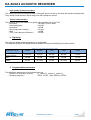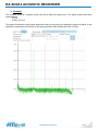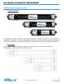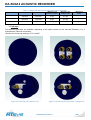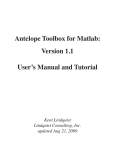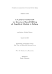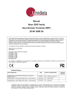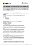
1
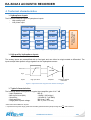
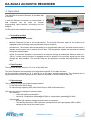
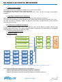
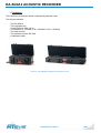
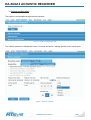
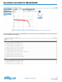
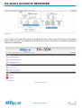
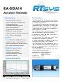
EA-SDA14 Acoustic Recorder Key features Description Autonomous and wired mode Until 4 hydrophones at the same time 24 bit data acquisition Selectable bandwidth acquisition Native 128 GB SD Card Programmable mission schedule Battery and attitude monitoring Calibration table for measurement accuracy The Acoustic Recorder accepts both passive and preamplified active hydrophones. Its wide band analog input allows until 1 MHz with a dynamic range greater than 100 dB which guarantees an efficient signal to noise ratio. The embedded digital signal processor allows high speed acquisition, filtering and storage. In autonomous mode, the data are stored on either a SD Card or a HDD. 300 or 700 m operating depth In wired mode, the data are stored then transferred with an Ethernet connection. Options 1 or 2 TB HDD or 600GB SSD memory Additional battery for larger autonomy Additional temperature / pressure sensors Low frequency acquisition module Fields of application Scientific instrumentation The EA-SDA14 can be programmed with a mission schedule that includes the start date and the active / standby periods of the record cycles to improve battery life. Short aluminum model characteristics: Dimensions: Length 320 mm Diameter 120 mm Weight (air): 5 kg Weight (water): 2 kg Autonomous passive recording Hydrophone network Typical application Max measured level Its power consumption is between 0.6 to 2.5 W operating and less than 1 mW in standby. The configuration and monitoring are done through a web browser interface. Offshore and environment Noise level The EA-SDA14 is a compact autonomous recorder that can simultaneously acquire the data of 4 wideband hydrophones. Sea-state 0 Input gain: 14.7 dB High quality hydrophone with SH = - 174 dB re V/µPA EA-SDA14 ACOUSTIC RECORDER Table of contents Technical characteristics Hydrophone inputs High quality hydrophone inputs Typical characteristics: Digitizing Programmable parameters Configuration examples Low power hydrophone inputs Embedded sensors Monitoring Power supply Data memory storage Operating limits Operation Recording modes Data Format Data storage Autonomy Battery life Storage capacity Available options Pressure (depth) and temperature sensors Hydrophone Adaptation Board GPS input HDD option Mounting brackets Communication cable Long range communication extension Low frequency acquisition module Mechanical characteristics Product overview Dimensions End caps Packaging Software User interface System configuration Contact RTSYS SAS Address Web site Phone Email Notes EA-SDA14 Data Sheet 3 3 3 3 4 4 4 4 5 5 5 5 5 6 6 6 6 7 7 7 8 8 8 8 8 8 9 9 9 12 12 12 13 14 15 15 16 19 19 19 19 19 19 20 2/20 EA-SDA14 ACOUSTIC RECORDER Technical characteristics Hydrophone inputs The EA-SDA14 has two types of hydrophone inputs: - High quality input - Low power input ADC Gain LP filter A ADC Gain LP filter C ADC Gain LP filter B ADC Gain LP filter D Active or Passive Hydrophones Low Power ADC Figure 1: Functional diagram of the hydrophone inputs High quality hydrophone inputs The analog inputs are preamplified with a fixed gain and can either be single ended or differential. The inputs accept wide dynamic range signals from the hydrophone sensor. Differential 14.7dB Single Inputs High pass filter Amplifier Analog-to-Digital Converter Figure 2: Input functional diagram with default 14.7dB gain Typical characteristics: The following values correspond to a typical input amplifier gain of 14.7 dB - Input impedance: 500 Ω * - Max Input Level (MIL) -10 dBV / 920 mVpp** - Sensitivity: -123 dBV (0.7 µV RMS) - High pass filter: 350 Hz at -3 dB* - Surge peak to peak voltage: 300 V (Time < 10 ms) * More values are available on request MIL ** A spurious free dynamic range greater than 80 dB is guaranteed with hydrophone signals of dBV maximum 2 EA-SDA14 Data Sheet 3/20 EA-SDA14 ACOUSTIC RECORDER Digitizing The analog to digital sampling frequency is configurable. The table below shows the ENOB (Effective Number Of Bits) and the SNR (Signal to Noise Ratio). Table 1 : Typical digitizing data Acquisition speed 39.0625 kS/s 78.125 kS/s 156.25 kS/s 312.5 kS/s 625 kS/s 1.25 MS/s 2.5 MS/s ENOB 20 bits 19.5 bits 19 bits 18.5 bits 18 bits 17.5 bits 17 bits SNR 108 dB 105 dB 102 dB 99 dB 96 dB 93 dB 90 dB Programmable parameters The digitization parameters of the hydrophones are: - Acquisition channel selection: A and/or B and/or C and/or D - Sampling frequency*: 2.5 MS/s, 1.25 MS/s, 625 kS/s, 312.5 kS/s, 156.25 kS/s, 78.125 kS/s, 39.0625 kS/s * All these frequencies include an anti-aliasing filter of 90 dB minimum Configuration examples Table 2 : Configuration examples Most common applications Mammal Studies Noise monitoring Piling Gain (dB) 14.7 0 14.7 0 0 -30 MIL (V) +/- 0.46 +/- 2.5 +/- 0.46 +/- 2.5 +/- 2.5 +/- 79 Sh (dB V/µPa) -170 -170 -155 -155 -200 -200 Max pressure level (dBµPa pp) 169.3 184 154.3 169 214 244 Low power hydrophone inputs The analog inputs A and C are connected to two low power acquisition channels to allow the lowest power consumption. The gain of these low power inputs is 0 dB. Typical characteristics: - Max Input Level (MIL) - Sensitivity : - High pass filter (set value): - Surge peak to peak voltage: 1.4 dB V / 1170 mVpp* -113 dB V (2 µV RMS) 100 Hz at - 3 dB 300 V (Time < 10 ms) * A spurious free dynamic range greater than 80dB is guaranteed with hydrophone signals of MIL 2 dB V maximum The analog to digital sampling frequency is configurable. The table below shows the ENOB (Effective Number Of Bits) and SNR (Signal to Noise Ratio). Table 3 : Low power digitizing data Acquisition speed Low Power(LP) ENOB SNR LP 48 kS/s LP 96 kS/s LP 192 kS/s 16.5 bits 16 bits 15.5 bits 99 dB 96 dB 93 dB EA-SDA14 Data Sheet 4/20 EA-SDA14 ACOUSTIC RECORDER Embedded sensors Table 4 : Available sensors accuracy and functions Sensor RTC (Real-Time Clock) with battery backup Accuracy Function +/-2 ppm 3 axis accelerometer 1 mG 3 axis gyroscope Optional Sensor Temperature (analog) Pressure (analog) GPS 8.75 mdps Accuracy +/-0.15 °C +/- 0.1% Full Scale +/- 1.5 m System clock Active and Standby 3 axis acceleration measurement (XYZ) Inclinometer with pitch and roll 3 axis gyration measurement Function Water temperature measurement Pressure measurement (Operating depth) System position Monitoring Table 5 : Monitoring functions Measure Power voltage (Vin) Power current (Iin) Board temperature Accuracy +/-10 mV +/-5 mA +/- 1 °C Function Power supply voltage monitoring Power supply current monitoring Board temperature monitoring Power supply Table 6 : Power supply capacity Power supply 6 x D Size Li-SOCl2 Battery Or 6 x D Size Alkaline Battery Ethernet Cable + Power supply Optional power supply 18 x D Size Li-SOCl2 Battery Extension 54x D Size Li-SOCl2 Battery Extension Li-Ion Battery Li-Ion Battery Extension Capacity* 216 Wh 91 Wh Capacity* 650 Wh 1950 Wh 156 Wh 468 Wh. Description Internal energy storage Internal energy storage Communication and power cable Description Extended room for 18 D Size Li-SOCl2 Batteries Extended room for 54 D Size Li-SOCl2 Batteries Rechargeable internal energy storage Rechargeable internal energy storage *These are indicative values that depend on the battery specifications Data memory storage Table 7: Data memory storage type and capacity Minimum storage SD Card (SD HC) SD Card (SD HC) Additional storage Mass storage (SSD) Hard drive 2.5’ Hard drive 2.5’ Capacity 128 GB 256 GB Capacity 600 GB 1 TB 2 TB Description WAV acoustic files recording WAV acoustic files recording Description WAV acoustic files recording WAV acoustic files recording WAV acoustic files recording Operating limits - Operation / Storage max temperature: - Hydrophone preamplifier max current: 0 to 70°C / -20 to 85°C 20 mA EA-SDA14 Data Sheet 5/20 EA-SDA14 ACOUSTIC RECORDER Operation The EA-SDA14 Acoustic Recorder is provided with a PoE box. It uses an Ethernet connection to communicate. A web interface can be used for mission programming, data collection, monitoring and live analysis. A LED push button indicates the recording status. Figure 3 : View of the EA-SDA14 recorder Recording modes Three recording modes are available: - Manual: Preferred for fast in situ measurement. The Acoustic Recorder waits for the button to be engaged to start recording a pre-programmed mission schedule. - Autonomous: The mission starts automatically at a programmed start time, and does several active / standby record cycles until it reaches its end date. The hydrophone signals are acquired and stored during the record phases. - Wired: The Acoustic Recorder is connected to a computer through its underwater Ethernet cable (10 100 m). It starts once the button is engaged and a live analysis of the acoustic signal can be done through the web interface. The acoustic data can be displayed, recorded and downloaded in realtime. Data Format The acquired data are stored in 16, 24 or 32 bit WAV files. The WAV filenames are composed of the acquisition channel ID, the date and time. All the acquisition channels (A, B, C and D) run at the same sampling frequency. The sampling rate is programmed with the user interface and the data are recorded on a multi-channel WAV file. Data storage The Acoustic Recorder has 2 data storage locations: A 128 GB or 256 GB SD Card An optional high capacity HDD (Hard Drive Disk) or SSD (solid-state drive) The user can select 2 strategies to store the data: SD Card only : o Limits the battery consumption. o Limited to 3 acquisition channels@625 kS/s or 4 acquisition channels@312 kS/s. - Hybrid mode o Allows high capacity storage and low power consumption. o The data are stored on a SD Card then, transferred onto the high capacity HDD or SSD storage at the end of the record cycles. EA-SDA14 Data Sheet 6/20 EA-SDA14 ACOUSTIC RECORDER Autonomy The autonomy of the Acoustic Recorder depends on: - The battery capacity - The storage capacity - The acquisition quality o High quality (Higher sampling rate and calibrated acquisition channels) o Low power o Low frequency - The recording strategy o SD Card only o Hybrid mode Battery life SD Card only continuous recording: Table 8 : Battery life with SD Card recording Configuration 6 Li-SOCl2 batteries 1 channel 140 h 2 channels 123 h 3 channels 109 h 4 channels 94 h Hybrid mode recording, 50% duty cycle: Table 9 : Battery life in hybrid mode Configuration 1 channel 2 channels 3 channels 4 channels 18 Li-SOCl2 batteries 781 h (32 Days) 688 h (28 Days) 611 h (25 Days) 530 h (22 Days) 54Li-SOCl2 batteries 96 Days 84 Days 75 Days 66 Days Storage capacity The indicative table below shows the necessary storage capacity* and the different sampling rates for 1 hydrophone channel acquisition. To respect the signal dynamics, the samples are saved as 16, 24 or 32 bit WAV files. In this example, the samples are saved as 24 bit files. Table 10 : Storage capacity and sampling rate for 1 hydrophone channel acquisition on a 24 bit file Acquisition speed 39.0625 kS/s 78.125 kS/s 156.25 kS/s 312.5 kS/s 625 kS/s 1.25 MS/s 2.5 MS/s Per hour 421 MB 844 MB 1.68 GB 3.4 GB 6.8 GB 13.5 GB 27 GB Per day 9.7 GB 19.3 GB 38.6 GB 77.3 GB 155 GB 324 GB 618 GB * The necessary memory size depends on the number of active channels. Data throughout (MB/s) = Nb of channels * Sampling freq S/s * Nb of Bytes / (1000 * 1000) Recommendations: - To maximize the battery life of the Acoustic Recorder, select the useful acquisition channels only. - The mission schedule has to be set: start / end time and active / standby period of the record cycles. EA-SDA14 Data Sheet 7/20 EA-SDA14 ACOUSTIC RECORDER Available options Pressure (depth) and temperature sensors There are 2 sensors rated to 200 or 700 meter depth. These high precision sensors are calibrated at 0.1% or 0.2% of the full-scale depending on the depth. Table 11 : Pressure and temperature sensor accuracy Depth 200 m 700 m Accuracy 0.1% / 0.2 m 0.2% / 0.7 m Hydrophone Adaptation Board This option allows the adjustment of the voltage and impedance and the attenuation of specific hydrophones. When ordering this option, please specify for each acquisition channel: - The necessary voltage, until 24 V - The necessary impedance, until 500 KΩ - The necessary attenuation factor (0 dB, -10 dB, -20 dB, -30 dB) Examples: - Passive hydrophones that require to be charged with very high impedances - High quality B&K or Reson hydrophones that require higher voltage power - Piling application that requires passive hydrophones and attenuated acquisition channels GPS input Once activated, this option acquires a GPS input from an external serial port and records NMEA data time logs in correlation with acoustic data. A separate timestamp data file is recorded to correlate the recorded sounds with the position of the Acoustic Recorder. When ordering this option, please specify if a dedicated 4 way SubConn input is necessary instead of a record acquisition channel. HDD option This option allows the Acoustic Recorder to acquire a larger quantity of data and to record at a higher frequency. The maximum recording speed ranges from 625 kS/s * 3 channels to 2.5 MS/s * 2 channels. 3 HDD options are available: - 1 TB HDD - 2 TB HDD - 600GB SSD Mounting brackets The mounting brackets are used to protect the Acoustic Recorder. They can be used to either mount the Acoustic Recorder onto a mooring line or to tow it from a boat. The mounting brackets are specifically made to operate with tensile stress. EA-SDA14 Data Sheet 8/20 EA-SDA14 ACOUSTIC RECORDER Communication cable The Acoustic Recorder is sold with a standard 10 m communication cable. This length can be customized to your needs until 100 m. For applications that require a long range deployment until 1.5 km, see § Long range communication extension. Long range communication extension Some applications require the long range remote monitoring of an acoustic environment. RTSYS provides an extension system that allows the remote control of the Acoustic Recorder until 1.5 km. The user can start the recording, monitor the behavior and acquire the data from the remote Acoustic Recorder while recording. Low frequency acquisition module To get a better acquisition below 2 kHz, a low frequency option can be added in parallel to the four high frequency acquisition system. This option is used for passive hydrophone only and consists of a dedicated front-end with four high quality low frequency ADC. Technical characteristics Low Frequency ADC Gain ALF Low Frequency ADC Gain CLF Low Frequency ADC Gain BLF Low Frequency ADC Gain DLF ADC Gain LP filter A ADC Gain LP filter C ADC Gain LP filter B ADC Gain LP filter D Passive Hydrophones Hydrophone inputs Figure 4 : Functional diagram of the hydrophone inputs with the low frequency option This new Acoustic Recorder configuration can either acquire: - 4 passive hydrophones with low frequency acquisition channels or - 4 passive hydrophones with high frequency acquisition channels or - 4 passive hydrophones with both low and high frequency acquisition channels EA-SDA14 Data Sheet 9/20 EA-SDA14 ACOUSTIC RECORDER High quality hydrophone inputs The analog inputs are preamplified with a fixed gain and are made to be used with passive hydrophones. They accept a wide dynamic signal range from the hydrophone sensor. Typical characteristics The following values are related to a typical input amplifier gain of 14.7 dB - Sensitivity: -130 dBV / 0.35 µV RMS - Pass band ripple: 0.03 dB - Stop band 135 dB - INL (Integral No Linearity) 0.5 ppm - SNR 130 dB - THD (Total Harmonic Distortion) -122 dB Digitizing The analog to digital sampling frequency is configurable. The table below shows the ENOB (Effective Number Of Bits) and SNR (Signal to Noise Ratio). Table 12 : Low frequency digitizing data Acquisition speed 250 S/s 500 S/s 1 kS/s 2 kS/s 4 kS/s Bandwidth -3 dB From 0.3 Hz to : 112.5 Hz* 225 Hz* 450 Hz* 900 Hz* 1.8 kHz* SNR 142 dB 136 dB 133 dB 130 dB 127 dB ENOB 22 bits 21.5 bits 21 bits 20.5 bits 20 bits * All these frequencies include an anti-aliasing filter of 135 dB minimum Programmable parameters The digitization parameters of the hydrophones are: - Selection of acquisition channel: ALF and/or BLF and/or CLF and/or DLF - Sampling frequency: 4 kS/s, 2 kS/s, 1 kS/s, 500 S/s, 250 S/s EA-SDA14 Data Sheet 10/20 EA-SDA14 ACOUSTIC RECORDER Example The example bellow is a dynamic range test with a high level signal input. The signal injected has these characteristics: - 125 Hz - -3 dBV (707 mV) This graph illustrates the high quality acquisition and the low noise floor despite the high level signal. It also shows the unexpected non-linearity of the signal generator HD2 (250Hz) and HD3 (375Hz). Figure 5: Measurement example – Spectral analysis on acquisition channel C at 1 kS/s EA-SDA14 Data Sheet 11/20 EA-SDA14 ACOUSTIC RECORDER Mechanical characteristics Product overview Figure 6: View of the model sizes of the EA-SDA14 Acoustic Recorder all operating until 700 m depth The waterproof housing is either a hard-anodized aluminum or POM-C central tube. The end caps are manufactured in POM-C. The surrounding protections are made of 316 L stainless-steel. They protect the connectors and allow for the setting of the shackles. They can be removed or used as mounting brackets. Dimensions The EA-SDA14 Acoustic Recorder is available in 3 model sizes: 1210mm, 550mm and 320mm. This allows an increased autonomy for longer mission Figure 7: Dimension drawing of the EA-SDA14 Acoustic Recorder models EA-SDA14 Data Sheet 12/20 EA-SDA14 ACOUSTIC RECORDER Table 13 : Weight and dimensions of the Acoustic Recorder models Length Diameter ≈ Weight in air Aluminum tube Weight in air POM-C tube ≈ Weight in water EA-SD14-320 320 mm 120 mm 5 kg 4.5 kg ½ weight in air EA-SD14-550 550 mm 120 mm 9 kg 8.5 kg ½ weight in air EA-SD14-1210 1210 mm 120 mm 20 kg 19 kg ½ weight in air Model End caps Four different end caps are available, depending of the option chosen on the Acoustic Recorder (1 to 4 hydrophones, Ethernet connection). Here are the 4 end cap settings: A, B, C and D. Figure 5.1: A End cap Figure 5.2: B End cap (here: 4 hydrophones) Figure 5.3: C End cap (here: Ethernet only Figure 5.4: D End cap (here: Ethernet & 1 hydrophone) EA-SDA14 Data Sheet 13/20 EA-SDA14 ACOUSTIC RECORDER Packaging The EA-SDA14 is delivered inside a waterproof protection case. The delivery includes: - The EA-SDA14 The hydrophone(s) A long Ethernet cable (10 m) The batteries (6 x LSH20 or 18 x LS33600 or 54 x LS33600) The User manual The software and the SD Card A calibration table Figure 8 : The EA-SDA14 waterproof protection cases EA-SDA14 Data Sheet 14/20 EA-SDA14 ACOUSTIC RECORDER Software The software is configurable with a web browser through an Ethernet cable. The web interface provides user-friendly access to the features of the Acoustic Recorder mother board. User interface - Scripts o Displays the live acquisition channels graph o Displays the live FFT of each acquisition channel o Activates a recording directly from the web interface for a quick analysis - System configuration Date and time configuration o System clock settings Mission schedule o Programming the active / standby periods of the record cycle(s) o Acquisition channels selection o Sampling frequency Network configuration o Fixed IP address or DHCP - Recorded files (access to the recorded WAV files) o Possibility to download the recorded data o Possibility to erase the stored data - Tools o o o o WAV file splitter, WAV header information Web browser and plugins Calibration table in pdf and excel format Datasheet in pdf format EA-SDA14 Data Sheet 15/20 EA-SDA14 ACOUSTIC RECORDER System configuration The system is configurable through the web interface: Figure 6: System configuration tab The mission schedule is defined with a start / end time and active / standby periods of the record cycle: Figure 7: Mission schedule EA-SDA14 Data Sheet 16/20 EA-SDA14 ACOUSTIC RECORDER Figure 8: Live measure example – Spectral analysis on acquisition channel A at 2.5 MS/s The Recorded files are listed on a dedicated tab. These files can be downloaded from the web interface or from a terminal (Command line). Figure 9: Recorded files tab EA-SDA14 Data Sheet 17/20 EA-SDA14 ACOUSTIC RECORDER Figure 9: Status tab There is also a Tools tab which allows the download of Firefox, Flash Player, RTWaveInfo, RTWaveSplit and EA-SDA14_Locator, the calibration table and the user manual. These pieces of software help the post analysis of recorded data. Figure 10: Tools tab EA-SDA14 Data Sheet 18/20 EA-SDA14 ACOUSTIC RECORDER Contact RTSYS SAS SIRET : RCS : Phone 52420113400029 Lorient B 524 201 134 Address +33 2 97 89 85 80 Email RTSYS 25 Rue Michel Marion 56850 CAUDAN – France [email protected] [email protected] ISO9001 :2008 Web site Certificate number : 2012042859 www.rtsys.eu The information furnished by RTSYS is believed to be accurate and reliable. However, RTSYS assumes no responsibility for the use of the information provided. EA-SDA14 Data Sheet 19/20 EA-SDA14 ACOUSTIC RECORDER Notes EASDA14-DS17_En EA-SDA14 Data Sheet 20/20