1
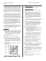
User's Manual: Series 270I
Model 270I Process Current Loop-Powered Isolator
INTRODUCTION:
Table of Contents
Page
Introduction..........................................................................
Description...........................................................................
Specifications .....................................................................
Installation ...........................................................................
Calibration ...........................................................................
General Maintenance ..........................................................
List of Drawings
These instructions cover the model types listed in Table 1
below. Supplementary sheets are attached for units with special
options or features.
1
1
2
3
4
4
Table 1:
A. Model Number Format:
1
270I-Input-Mounting-Certification
1
B. Typical Model Number: 270I-20MA-DIN-NCR
Page
Electrical Connections (4501-106).........................................
Calibration Connection & Simplified Schematic (4501-105)..
Dimensions: DIN Rail Mounting (4501-107)...........................
Dimensions: Surface & Snaptrack Mtg. (4501-108)..............
NEMA 4 & 12 Enclosures (4501-109)...................................
Explosion Proof Enclosure (4501-110)..................................
Series
270I
6
7
8
9
10
11
-Input
20MA
-Mounting
-DIN
-SM
-ST
-N4
-N12
-XP
-Certification
2
-NCR
Notes (Table 1):
1. All units are factory calibrated for 4 to 20mA (no "-C" needed).
2. Consult the factory for current information on agency (e.g.
Canadian Standards Association, etc.) approvals.
DESCRIPTION:
This two-wire, loop-powered isolator accepts a 4 to 20mA input
signal and provides an isolated 4 to 20mA output signal. It is
designed to break the galvanic path between a transmitted signal
source and the receiving device. The isolator is highly effective in
eliminating unreliable or inaccurate signal transfer by providing total
current-to-current signal isolation. The isolator is RFI-protected,
operates over a wide temperature range, and features excellent
temperature coefficients, which minimize the effects from harsh
plant environments. See Drawing 4501-105 for a simplified
schematic.
IMPORTANT SAFETY CONSIDERATIONS
It is very important for the user to consider the possible adverse
effects of power, wiring, component, sensor, or software failures in
designing any type of control or monitoring system. This is
especially important where economic property loss or human life is
involved. It is important that the user employ satisfactory overall
system design. It is agreed between the Buyer and Acromag, that
this is the Buyer's responsibility.
Key 270I Features:
√
√
√
√
Acromag, Inc.
30765 South Wixom Road
P.O. Box 437
Wixom, Michigan 48393-7037, USA
Transformer Isolation
Signal Loop
Powered
0-600Ω Load Range
High Accuracy
√
√
No Load Trimming Required
Wide Temperature Range
√
√
Input Current Sense Resistor
Versatile Mounting Configuration
Power to operate the unit is derived from the input signal
current--no external power supply is required. When a signal
isolation device is installed, it is important to consider the voltage
drop or additional line resistance that will be placed in the system.
Any additional load tends to reduce the line or drive potential and
may exceed the source rating. The effect of voltage drop within the
system must be calculated to ensure that drive capability is not
exceeded. Total maximum voltage drop in the input current loop is
the sum of the isolator's fixed voltage drop, plus the voltage required
to drive the output load. The output load resistance range is from 0
to 600 ohms.
Tel: (248) 624-1541
FAX: (248) 624-9234
Copyright 1991, 1994, Acromag, Inc. Printed in the USA.
Data and specifications are subject to change without notice.
8500-288-B94C002
-1-
Series 270I User's Manual
Isolator
Process Current Loop-Powered
____________________________________________________________________________________
Equation (Refer to Figure 1):
Input Voltage Drop = 5.4V DC + (0.0216A x R-load)
Placing a resistor across the output terminals will provide a
voltage output proportional to the loop current, such as; 1 to 5V DC
(4 to 20mA) for a 250 ohm load.. A unique feature of this isolator is
that once it is calibrated, it does not have to be recalibrated for
different loads (up to 600 ohms). That is, calibration is independant
of the load. The isolator is calibrated at the factory with a 250 ohm
load and the need for a load trim adjustment is not required for other
load values.
Example (R-load = 250 ohms):
Input Voltage Drop = 5.4V DC + (0.0216A x 250Ω) = 10.8V
DC.
Current Sense Resistor: A built-in 10 ohm (±0.1%) resistor is
available to monitor the input current to the isolator. The wiring
to the isolator's input terminals determines if this resistor is
included in the current loop or not. The use of this resistor
provides a test signal of 40mV to 200mV, representing 4 to
20mA. See Drawing 4501-106 for wiring details. Note that the
use of this resistor will increase the Input Voltage Drop by
200mV (10 ohms x 20mA).
To facilitate field indication of the current going into the isolator,
the user has the option to wire the input to include a built-in 10Ω
resistor (±0.1%, ±25ppm/oC) in the current loop. This provides a
test signal of 40 to 200mV that is directly proportional to the 4 to
20mA input signal. The only penalty is the increased fixed voltage
drop that results (200mV). Again, the use of this resistor is optional.
Input V-Drop = 5.4VDC +(0.0216A xR-load), no sense resistor.
Input V-Drop = 5.6VDC +(0.0216A xR-load), w/ sense resistor.
These field mounted loop-powered isolators are designed to
utilize one of a number of customer-specified mounting
configurations. The isolator is available for DIN-rail mounting,
surface mounting, 3-inch SNAPTRACKTM plastic rail mounting, or
in various housings. These housings include NEMA 4, 12, and
explosion-proof enclosures. The model number of the unit specifies
the mounting/enclosure type (refer to Table 1).
Isolation: The input and output circuits are isolated from each
other for common-mode voltages up to 250V AC, or 354V DC
off ground, on a continuous basis (will withstand 1500V AC
dielectric strength test for one minute without breakdown). This
complies with the test requirements outlined in ANSI/ISAS82.01-1988 for the voltage rating specified.
Input wiring is inserted in the top of the unit, while output wiring
is inserted in the bottom, or field side of the unit. Screws to secure
the wiring are located on the front panel. Connectors are screwclamp type and accept wire size up to #14 AWG.
Output: 4-20mA DC output into 0 to 600 ohms.
A. For R-load from 50 to 600 ohms: Connect R-load between
the Output(+) and Output(-) terminals.
B. For R-load from 0 to 50 ohms: Connect R-load between the
Output(S) and Output(-) terminals. For optimum
performance at low values of R-load, the isolator has a builtin pad resistor of 50 ohms.
SPECIFICATIONS:
Function: This loop powered isolator accepts a 4 to 20mA input
signal, provides input-to-output circuit isolation, and produces a
4 to 20mA output for loads from 0 to 600 ohms. Zero and span
trim adjustments utilize 22-turn potentiometers accessible from
the front of the unit. The isolator has various mounting and
enclosure options available.
1. Input Voltage Drop (with the input sense resistor not used):
Input Voltage Drop = 5.4VDC +[0.0216A x (R-load + 50Ω)]
2. Input Voltage Drop (with the input sense resistor used):
Input Voltage Drop = 5.6VDC +[0.0216A x (R-load + 50Ω)]
MODEL/SERIES: 270I- (Color coded with a Red label)
Reference Test Conditions: Input/Output current: 4 to 20mA;
output load 250 ohms; 77oF (25oC) ambient.
INPUT:- 20MA: 4 to 20mA input. Power to operate the loopisolator is derived from the input signal loop. Input current
should be limited to less than 50mA to prevent damage to the
isolator. In the event of an open output circuit, the input loop
voltage drop is limited to 20V, nominal. Isolator has reverse
polarity protection.
Accuracy: Better than ±0.1% of output span. This error includes
the combined effects of isolator repeatability, hysteresis,
terminal point linearity, and adjustment resolution.
Ambient Temperature Range: -13oF to 185oF (-25oC to 85oC).
Input Voltage Drop: The input voltage drop is a function of the
input current as follows:
Vinput
18.36V
Rinput
850Ω
16.20V
750Ω
14.04V
650Ω
11.88V
550Ω
9.72V
450Ω
7.56V
350Ω
5.40V
250Ω
0
Ambient Temperature Effect: Less than ±0.006% of output span
per oF (± 0.01% per oC) over the ambient temperature range
for reference test conditions (Specification includes the
combined effects of zero and span over temperature).
Load Resistance Effect: Less than ± 0.1% of output span as load
resistance is changed over entire range. Allows use of isolator,
within resistance load range, without the need to recalibrate the
isolator for a particular load.
Output Ripple: Less than ±0.1% of the maximum output span.
Bandwidth: -3 dB at 3 Hz, typical.
100 200 300 400 500 600
OUTPUT LOAD RESISTANCE (Ω)
Response Time: For a step input, the output reaches 98% of
output span within 80mS, typical.
)LJXUH ,QSXW %XUGHQ YV 2XWSXW /RDG P$ /RRS &XUUHQW
-2-
Series 270I User's Manual
Isolator
Process Current Loop-Powered
____________________________________________________________________________________
Explosion Proof, Water-Tight Enclosures: Option type
listed below. Refer to Drawing 4501-110 (no display window)
for outline and clearance dimensions. Enclosure Materials:
Body and cover - Copper-free aluminum (less than 0.4%),
Gasket - Neoprene. Finish: Corro-free epoxy powder coat,
color gray. Hub size: 0.75 inch (Quantity 2). Housing meets
Class I - Groups B, C, & D, Class II - Groups E, F, & G, Class III,
and NEMA 4 (water-tight) requirements. Isolator is mounted
within enclosure at the factory.
Noise Rejection:
Common Mode: Better than 110dB at 60 Hz, typical.
RFI Resistance: Less than ± 0.5% of output span with RFI field
strengths of up to 10V/meter at frequencies of 27MHz, 151MHz,
and 467MHz.
EMI Resistance: Less than ±0.25% of output span effect with
switching solenoids or commutator motors.
Surge Withstand Capability (SWC): Input/Output terminations
rated per ANSI/IEEE C37.90-1978. Unit is tested to a
standardized test waveform that is representative of surges
(high frequency transient electrical interference), observed in
actual installations.
-XP:
Explosion Proof, Water-Tight Enclosure (No Window).
Shipping weight: 5 pounds (2.3Kg) packed.
CERTIFICATION: Consult the factory for current information on the
availability of agency (e.g. Canadian Standards Association,
Factory Mutual, etc.) approvals.
Construction (Basic Isolator):
Circuit Board: Military grade FR-4 epoxy glass circuit board.
Circuit Board Coating: Fungus resistant acrylic conformal coat.
Terminals: Compression type, wire size 14 AWG maximum.
Mounting Position: Position insensitive.
Case: Self-extinguishing NYLON Type 6.6 polyamide black
thermo-plastic UL94- V-2, General Purpose, NEMA Type 1
enclosure
-NCR: No Certification Required.
INSTALLATION:
The isolator is packaged in a general purpose plastic housing
and optionally mounted within a variety of protective enclosures.
The isolator should be located in an area that is protected from dust,
moisture, and corrosive atmospheres. The enclosure type
determines the protection afforded in a particular environment and
location, make sure that this is not compromised. Maximum
operating ambient temperatures should be within -13 oF to 185oF
(-25 oC to 85oC) for satisfactory performance. If unit is factory
calibrated, it is ready for installation. Connect as shown in
Connection Drawing 4501-106. To verify calibration, refer to the
"CALIBRATION" section.
MOUNTING: A wide variety of mounting options and enclosures
are available to meet the needs of the installation. The
available models are listed below. The isolator is shipped as a
complete assembly.
-DIN: General Purpose Housing, DIN Rail-Mount - "G" & "T"
rails. "G" Rail (32mm), Type EN50035; "T" Rail (35mm),
Type EN50022. Refer to Drawing 4501-107 for outline
and clearance dimensions. Shipping Weight: 1 pound
(0.45 Kg) packed.
-SM: General Purpose Housing, Surface-Mount. Refer to
Drawing 4501-108 for outline and clearance dimensions.
Shipping Weight: 1 pound (0.45 Kg) packed.
-ST: General Purpose Housing, SNAPTRACK™. Refer to
Drawing 4501-108 for outline and clearance dimensions.
Shipping Weight: 1 pound (0.45 Kg) packed.
SNAPTRACK™ is a registered trademark of Reed
Devices, Inc.
Mounting: Mount isolator assembly - refer to appropriate outline
drawing for mounting and clearance dimensions. Determine
which configuration is utilized and consult the proper mounting
instructions listed below.
1. DIN Rail Mounting: Use suitable fastening hardware to
secure the DIN rail to the designated mounting surface. An
isolator ordered with the DIN Rail mounting option (-DIN)
can be mounted to either the "T" or "G" Rail. Installation of
the isolator to the rail depends on the type of DIN rail used
(see Drawing 4501-107). Units can be mounted side-byside on 1.0-inch centers, if required.
2. Surface Mounting: Secure the isolator to the designated
mounting surface using two 6-32 screws. Note that the
mounting bracket has screw slots to facilitate mounting.
Units can be mounted side-by-side on 1.0-inch centers, if
required.
NEMA 4 and 12 Enclosures: Option types listed below.
Refer to Drawing 4501-109 for outline and clearance
dimensions. Isolator is mounted within enclosure at the factory.
These enclosures may accommodate a second Series 270I
isolator with the Surface-Mount option (-SM option, ordered
separately). Conduit mounting holes and fittings are customer
supplied.
-N4: Water-Tight Enclosure, NEMA 4. Enclosure material
and finish: 0.075 and 0.060 inch thick steel with gray
hammertone enamel finish inside and out. Shipping
weight: 6 pounds (2.7 Kg) packed.
-N12: Oil-Tight Enclosure, NEMA 12. Enclosure material
and
finish: 0.075 and 0.060 inch thick steel with gray
hammertone enamel finish inside and out. Shipping
weight: 6 pounds (2.7 Kg) packed.
-3-
Series 270I User's Manual
Isolator
Process Current Loop-Powered
____________________________________________________________________________________
3. SNAPTRACK™ Mounting: Secure the SNAPTRACK™
mounting channel to the designated mounting surface using
suitable fastening hardware. To install the unit in the
mounting channel, place the bottom end of the mounting
bracket between the rails and press the top (notched end)
firmly until the bracket "snaps" into place. To remove the
isolator, insert a screwdriver into the upper arm of the
connector, twist to release the unit from the track and tip the
unit out. Units can be mounted side-by-side on 1.0-inch
centers, if required.
3. Grounding: The isolator in the General Purpose Housing
is plastic and does not require an earth ground connection.
If the isolator is mounted in a metal housing, a ground wire
connection is required. Connect the ground terminal
(Green Screw) to a suitable earth ground using suitable
wire per applicable codes.
CALIBRATION:
All units are calibrated and checked for proper performance at
the factory before they are shipped. The calibration example below
is provided for reference.
4. NEMA 4 & 12 Enclosure Mounting: Secure the enclosure
assembly to the designated mounting surface using
appropriate hardware. The isolator is secured within this
enclosure using two screws. Note: It is recommended that
the isolator be removed from the enclosure during the
process of drilling holes, installing fittings, and mounting the
enclosure.
Isolator - Adjustment Procedure:
Connect the isolator as shown in Connection Drawing
4501-106. The input current source must be adjustable over the
entire input range of the unit and settable to an accuracy of 0.05% or
better, for proper results.
Note: It is recommended that the isolator be removed from
the enclosure during the process of mounting the enclosure.
To remove the unit from the enclosure, remove two screws
securing it to the bottom of the enclosure. After the
enclosure is installed, install the isolator into the enclosure.
Position the unit at an angle that permits all wiring to be
routed unobstructed through both ports. If the isolator has
the display option, make sure the orientation of the display
allows for easy reading once installed. Secure the isolator
assembly to the enclosure using two screws.
The Zero and Span adjustments are accessible on the front
panel of the isolator (see Drawing 4501-106 for their location). The
screwdriver blade, used to adjust the potentiometers, should not be
more than 0.1 inch (2.54mm) wide.
Isolator - Calibration Example:
MODEL : 270I-20MA-DIN-NCR
Output : 4-20mA
Input : 4-20mA
Electrical Connections:
1. Set the input source to 4.000mA. Adjust the Zero (Z) pot until
the output reads 4.000mA DC.
2. Set the input source to 20.000mA. Adjust the Span (S) pot until
the output reads 20.000mA DC.
3. Repeat steps 1 and 2 until the readings converge. The
instrument is now calibrated. Several mid-point values should
also be checked to verify proper operation of the isolator.
The wire size used to connect the unit to the control system is
not critical. All terminal strips can accommodate wire from 14-26
AWG. Strip back wire insulation 1/4-inch on each lead before
installing into the terminal block. Input wiring may be shielded or
unshielded twisted pair. Output wires should be twisted pair. Since
common mode voltages can exist on signal wiring, adequate wire
insulation should be used and proper wiring practices followed. It is
recommended that input wiring be separated from output signal
wiring for safety, as well as for low noise pickup.
GENERAL MAINTENANCE:
1. Input: Connect input per connection diagram. Observe
proper polarity. Note: Input/Output circuits are isolated from
each other allowing the output circuit to operate with
common mode voltages up to 250V AC or 354V DC off
ground on a continuous basis. The power to operate this
loop-isolator is derived from the input signal. For a 250
ohm load, the input voltage drop with 20mA output is
10.8VDC (5.4VDC + (0.0216 x R-load)). Determine the
input voltage requirements for your load. Make sure your
input source is capable of handling the required voltage
drop.
The isolator contains solid-state components and requires no
maintenance, except for periodic cleaning and calibration
verification. When a failure is suspected, a convenient method for
identifying a faulty isolator is to exchange it with a known good unit.
It is highly recommended that a non-functioning isolator be returned
to Acromag for repair, since Acromag used tested and burned-in
parts, and in some cases, parts that have been selected for
characteristics beyond that specified by the manufacturer. Further,
Acromag has automated test equipment that thoroughly checks the
performance of each isolator.
2. Output: Make output circuit connections to the loopisolator as shown in the Connection Drawing 4501-106.
The
4-20mA DC output signal can be used with a resistor load
from 0 to 600 ohms. For resistance loads from 50 to 600
ohms, connect R-load between the Output(+) and Output(-)
terminals. For resistance loads from 0 to 50 ohms, connect
R-load between the Output(S) and Output(-) terminals. The
Output(S) terminal has a built-in padding resistor of 50
ohms.
-4-