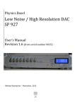
1
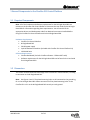
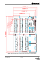
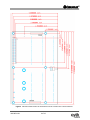
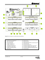
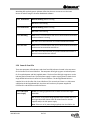
User Manual Circaflex 511 Control Platform NI Single-Board RIO Based OEM Devices Part Number: 920-00511-01 Note: If this is the first time you are using the NI Single-Board RIO 9606/9605, please refer to the User Guide for the NI Single-Board RIO before using this manual. This document instructs the user how to use the Circaflex 511 Control Platform to simplify and accelerate I/O control, prototyping and product development using the NI Single-Board RIO. This embedded control system has been developed to allow simple and rapid connectivity to the I/O available on the NI Single-Board RIO device without needing multiple cables and breakout boards. In addition to rapid connectivity there are other features like fuse protection, LED indication, signal conditioning and prebuilt LabVIEW code that have also been included with the system to further accelerate the control process. Once you finalize the design of your control system, Cyth Systems can create for you a connectivity board with customized layout and circuitry. Safety Information Caution: Do not use the board for any purposes other than what is specified in this documentation. This may compromise the safety of the product and other hazards may arise if the device is used improperly. If the product is damaged, please send it back to Cyth Systems for proper repair. Caution: Do not modify or install unspecified parts to the device because this may introduce dangerous hazards. Only use the product with the chassis, modules, accessories, and cables specified in the installation instructions. Caution: Keep the unit free from contaminants and completely dry before using. Caution: The 3.3V I/O terminals are not compatible for any voltage over 3.3V or under 0V. Violation of this can potentially damage the NI Single-Board RIO. 410-00511-01 1 of 12 1 General Components to the Circaflex 511 Control Platform 1.1 Required Components Note: All of the hardware and software requirements for the NI Single-Board RIO are relevant to the Circaflex 511 Control Platform. Please see the User Guide for the NI SingleBoard RIO for information regarding those requirements. You will need all of the appropriate drivers and development code from National Instruments installed before using the Circaflex 511 Control Platform with the NI Single-Board RIO. Hardware Requirements Circaflex 511 Control Platform NI Single-Board RIO 24V DC power supply Cyth M1 flathead screwdriver (included with Circaflex 511 Control Platform kit) 16-30 AWG wire Software Requirements Circaflex Dashboard (Pre-built Circaflex software – FPGA and RT code) Software requirements for the NI Single-Board RIO can be found in the User Guide for NI Single-Board RIO 1.2 Dimensions This section contains dimensional drawings of the Circaflex 511 Control Platform, including its connector to the NI Single-Board RIO. Note: See Figures 1 and 2. The plated mounting holes are all connected to the ground lug, P1 on the NI Single-Board RIO. Please connect one of the plated mounting holes on the Circaflex 511 or P1 on the NI Single-Board RIO securely to earth ground. 410-00511-01 2 of 12 Figure 1 Mechanical dimensions of the top view of the Circaflex 511 Control Platform. 410-00511-01 3 of 12 Figure 2 Mechanical dimensions of the bottom view of Circaflex 511 Control Platform. 410-00511-01 4 of 12 Figure 3 Item location on Circaflex 511 Control Platform. 1 2 3 4 5 6 7 8 9 10 Circaflex power in connector (24V) System status LED indicators Power LED indicators Fuse LED indicators Circaflex module slot 1 Circaflex module slot 2 3.3V digital I/O signal bank 5V digital input signal bank 5V digital output signal bank LED indicator 410-00511-01 11 12 13 14 15 16 17 18 19 20 5 of 12 Channel number Signal terminal Ground terminal Single-Board RIO power out connector (24V) 5V terminal bank Power distribution bank 24V industrial digital output signal bank 24V industrial digital input signal bank 24V industrial digital input PNP signal bank 24V terminal(s) 1.3 Hardware Setup The Circaflex 511 Control Platform is a plug-in adapter that provides access to the I/O available on the NI Single-Board RIO. Use 10mm standoffs between the NI Single-Board RIO and Circaflex 511 Control Platform at the mounting holes. When connecting the Circaflex 511 Control Platform to the NI Single-Board RIO, align the RMC connector on Circaflex 511 to the RMC connector on the NI Single-Board RIO. After correct alignment, press evenly on the Circaflex 511 until the I/O connector is all the way in and the Circaflex 511 Control Platform rests above the NI Single-Board RIO evenly. With the card plugged in, you can immediately use the screw terminals on the Circaflex 511 Control Platform to make connections to the I/O on the NI Single-Board RIO. It is recommended that you use the screwdriver included with the Circaflex 511 Control Platform kit on the screw terminals found on the Circaflex 511 to prevent damage to the screw terminals. Caution The maximum torque for tightening the screw terminals is 1.35 in-lb (0.15 Nm). Please use caution when tightening screw terminals. DO NOT OVERTIGHTEN. The silkscreen labels on the board represent the actual digital channels on the NI SingleBoard RIO. All grounds on the board are connected. 1.4 Powering the Circaflex 511 Control Platform The Circaflex 511 Control Platform requires a 24V DC power supply. In order to supply power to the Circaflex 511, connect the supplied 24V power supply to the Circaflex 511, where the power barrel connector reads “24Vdc In.” The power requirement for your application can be measured by finding the power consumption during execution and add 20% to your estimates for transient and startup conditions. 1.5 Connecting to the Circaflex 511 Control Platform The NI Single-Board RIO connected to the Circaflex 511 Control Platform includes an Ethernet port in which an Ethernet cable connects the NI Single-Board RIO to a computer. Connect a Gig-E or cross-over Ethernet cable from the NI Single-Board RIO to the computer. On the computer, enable the Ethernet connection to the NI Single-Board RIO on the computer. 410-00511-01 6 of 12 1.6 Pre-Built Circaflex 511 Software Cyth Systems has developed FPGA and RT code to get you started in your application. This gives you access to all of the I/O on Circaflex 511, to make an easily modifiable GUI, and to create logic. Setup A. Configure Computer Ethernet Settings This gives access to all the I/O on Circaflex 511. To set up your computer to communicate with Circaflex 511, perform the following steps: 1. 2. 3. 4. 5. 6. 7. 8. Open Control Panel. Select Network and Sharing Center. On the left, click Change Adapter Settings. Right-click on the port that will be used to connect to the Circaflex 511, then click Properties. Double-click on Internet Protocol Version 4. Enter the following IP address: 100.100.100.1 Enter the following Subnet mask: 255.255.255.0 Click OK, then click OK again. B. Install Software To install the Circaflex Dashboard onto your computer, perform the following steps: 1. Supply power to Circaflex 511 by plugging in the power cable to an outlet and connecting the other end to the power connector on Circaflex 511. 2. Connect Circaflex 511 to your computer by plugging the Ethernet cable from Circaflex to your computer. 3. Insert the Circaflex Dashboard CD into your computer and follow the directions to install the software. 4. Open the Circaflex Dashboard by double-clicking on the shortcut on your desktop or selecting it under your programs. 2 Integrated I/O in the Circaflex 511 Control Platform 2.1 Integrated 3.3V Digital I/O The Circaflex 511 Control Platform offers 12 screw terminals for 3.3V TTL digital I/O. Each of these terminals can each be configured to be an input or an output. Please refer to the 410-00511-01 7 of 12 Specifications 3.3V section for details on maximum and minimum current and voltage capacities. Note: These terminals are not compatible for any voltage over 3.3V control or power. This will potentially damage the NI Single-Board RIO. The 3.3V I/O terminal bank are programmable to be all inputs or all outputs. 2.2 Integrated 5V Digital I/O The Circaflex 511 Control Platform offers 12 screw terminals for 5V digital input, 12 screw terminals for 5V digital output, and eight screw terminals for 5V power distribution. Please refer to the Specifications 5V section for details on maximum and minimum current and voltage capacities. 2.3 Integrated 24V Digital I/O and PNP The Circaflex 511 Control Platform offers eight screw terminals for 24V industrial digital input, two screw terminals for 24V industrial digital sensor PNP, 11 screw terminals for 24V industrial digital output, and ten screw terminals for 24V power distribution. Please refer to the Specifications 24V I/O section for details on maximum and minimum current and voltage capacities. 2.4 Integrated Expansion Module Ports The Circaflex 511 Control Platform offers two ports for Circaflex expansion modules in which analog I/O modules, SSR, RTD, Reed Relay or other modules can be placed. Please contact Cyth Systems for the complete list of Circaflex expansion modules for additional I/O on the Circaflex 511 Control Platform. 2.5 LED Indications There is an LED indicator on every digital I/O. These I/O LED indicators will be green when the signal has gone high. 2.51 System Status LEDs There are four system status indication LEDs located at the top left corner of the Circaflex 511 Control Platform. RTOS status LED will blink when the real-time operating system is running. The FPGA status LED will blink when the FPGA is active. The User LED and the 410-00511-01 8 of 12 Watchdog LED are both generic indicator LEDs that the user can use to turn their own device on and off using the Circaflex Dashboard software. 2.52 RTOS Status White & Blinking: RTOS is running. Off: RTOS is not running. 2.53 FPGA Status White & Blinking: FPGA is running. Off: FPGA is not running. 2.54 Watchdog Blue: There is communication with the Circaflex Dashboard software and the software is running. Off: There is no communication to Circaflex Dashboard software. 2.55 User LED Blue: There is communication with the Circaflex Dashboard software and the user has turned the User LED on. Off: There is no communication to Circaflex Dashboard software or the user has turned the User LED off. 2.56 Power & Fuse LEDs There are two power LED indicators and three fuse LED indicators located in the top corner of the Circaflex 511 Control Platform. The two power LEDs light up green to indicate power for 5V supplied power and 24V supplied power. The three fuse LEDs light up green or red to indicate good or blown fuses. The 24V power supply is used to supply power to both the NI Single-Board RIO and the Circaflex 511 Control Platform. The NI Single-Board RIO then supplies 5V to the Circaflex 511 Control Platform. This means that if there is no 24V power supplied to the NI Single-Board RIO, then there will not be any 5V power supplied to Circaflex 511 and therefore no LEDs will be on. 2.57 5Vdc Input Power Supply Green: 5V is being supplied to the Circaflex 511 from the SingleBoard RIO. Off: There is no 5V power being supplied to the Circaflex 511 from the Single-Board RIO. Please check for blown fuses for the 24V supplies and/or the 24V power supply. Note: If there is no 5V power being supplied, then the LED for the 410-00511-01 9 of 12 5Vdc 1.5A Fused Supply will also be off. 2.58 5Vdc 1.5A Fused Supply Green: 5V is being supplied to the Circaflex 511 from Single-Board RIO and the 1.5A fuse is good. Red: 5V is being supplied to the Circaflex daughterboard from the Single-Board RIO and the 1.5A fuse is blown. Please replace this fuse. Off: There is no 5V power being supplied to the Circaflex 511from the Single-Board RIO. Note: If there is no 5V power being supplied, then the LED for the 5Vdc Input will also be off. Since 5V is supplied via the Single-Board RIO and the Single-Board RIO power is supplied via the 24V power supply connected to the Circaflex 511, check for blown fuses for the 24V supplies and/or the 24V power supply. 2.59 24Vdc Input Power Supply Green: 24V is being supplied to Circaflex 511 from the 24V power supply. Off: There is no 24V power being supplied to the Circaflex 511 from the power supply. Please connect the power supply to 3 and plug in the power supply to an outlet. on Figure Note: If there is no 24V power being supplied, then all of the power and fuse LEDs will be off. This includes LEDs for the 24Vdc Input, 24Vdc 1.5A Single-Board RIO Sup, and 5V LEDs will also be off. 2.60 24Vdc 4A Fused Supply Green: 24V is being supplied to the Circaflex 511 from the power supply and the 4A fuse is good. Red: 24V is being supplied to the Circaflex 511 from the power supply and the 4A fuse is blown. Please replace this fuse. Off: Refer to Section 2.58 for the “Off” indication. 2.61 24Vdc 1.5A Fused sbRIO Supply Green: 24V is being supplied to the Circaflex 511 from the power supply and the 1.5A fuse to protect the Single-Board RIO is good. Red: 24V is being supplied to the Circaflex 511 from the power supply and the 1.5A fuse to protect the Single-Board RIO is blown. Please replace this fuse. Off: Refer to Section 2.58 for the “Off” indication. 410-00511-01 10 of 12 3 Specifications to the Circaflex 511 Control System 3.1 GENERAL NI Single-Board RIO ................................................................................... 9606 Processesor Type ...................................................................................... Freescale Real-Time Processor Speed ........................................................................................ 400 MHz Nonvolatile Storage .................................................................................. 512 MB FPGA Type ................................................................................................. Xilinx Spartan-6 LX45 FPGA Size .................................................................................................. 2 M Gates 3.2 NETWORK Network Interface ..................................................................................... 10/100 Ethernet Communication Rates ............................................................................... 10 Mb/s, 100 Mb/s Autonegotiated Maximum Cabling Distance ...................................................................... 100 Meters (328 Feet) 3.3 POWER REQUIREMENTS Power Supply Voltage Range .................................................................... 24V Power Usage (Quiescent) ......................................................................... 8.00W 3.4 POWER SUPPLY TERMINALS 24V Current ............................................................................................... 3.75A Max, 4A Fused 5V Current ................................................................................................. 1.25A Max, 1.5A Fused 3.5 3.3V TTL DIGITAL INPUT/OUTPUT Not 5V Compatible Max Current Per Channel.......................................................................... 3mA Maximum Speed ....................................................................................... 10MHz Output High Voltage ................................................................................. 2.70V - 3.30V Output Low Voltage .................................................................................. 0.07V - 0.54V Input High Voltage .................................................................................... 2.00V - 3.465V Input Low Voltage ..................................................................................... 0.00V - 0.80V 3.6 5V DIGITAL INPUT Input Low Voltage ..................................................................................... 0.00V - 1.33V Input High Voltage .................................................................................... 3.33V - 5.50V 3.7 5V DIGITAL OUTPUT On-State Resistance .................................................................................. 350mΩ Nominal Load Current ............................................................................... 300mA Turn-On Time (Load Resistance 47Ω) ....................................................... 140μs Turn-Off Time (Load Resistance 47Ω) ....................................................... 170μs 3.8 24V INDUSTRIAL DIGITAL INPUT Input Type ................................................................................................. Sinking OFF State Input Voltage ............................................................................ ≤ 6.4V 410-00511-01 11 of 12 OFF State Input Current ............................................................................ ≤ 47μA ON State Input Voltage ............................................................................. ≥ 16V ON State Input Current ............................................................................. ≥ 118μA Maximum Speed ....................................................................................... 100kHz Maximum Voltage ..................................................................................... 27.7V 3.9 24V INDUSTRIAL DIGITAL OUTPUT Output Type .............................................................................................. Sourcing Output Current Per Channel ..................................................................... 250mA Max Maximum Speed ............................................................... ....................... 1.5kHz 3.10 ANALOG INPUT Available in Circaflex Expansion Modules* 3.11 ANALOG OUTPUT Available in Circaflex Expansion Modules* 3.12 PHYSICAL CHARACTERISTICS Weight....................................................................................................... 316.0 g (11.15 oz) Standoff Size ............................................................................................. 10mm Torque for Screw Terminals ...................................................................... 0.15 N•m (1.35 lb•in.) Tightening Torque Max for Screw Terminals ............................................ 1.35 in-lb Screw Threads ........................................................................................... M1, 6 Type of Wire to Connect to Circaflex 511 ................................................. Stranded Wire Wire Gage Range ...................................................................................... 16-30 AWG 3.13 Compliance Cyth Systems makes no safety, compatibility or CE marking claims for Circaflex 511. The end user is responsible for conformity to any and all compliance requirements. 3.14 Environmental Circaflex 511 is intended for indoor use only and is intended to be built into a suitable enclosure for electronics and computing devices. Please refer to the NI Single-Board RIO User Guide for its environmental specs. Operating Temperature Range ................................................................. -30°C to +85°C 4 Support Cyth Systems is located at 9939 Via Pasar, San Diego, California, 92126. For technical support in the United States, please call +1 888 508 7355 or email [email protected]. For telephone support outside of United States and Central America, please call +44 8455 197813. © 2012 Cyth Systems, Inc. All rights reserved. Product and company names are trademarks or trade names of their respective companies. 410-00511-01 12 of 12