1
Displacement sensor control unit UQ1 series
User’s manual
Introduction
Thank you for purchasing the displacement sensor I/F unit UQ1 series. Before using this product, please
confirm this product is what you need.
●
Please read this manual thoroughly and keep this manual at hand for proper use.
●
When you lost this manual or had any questions and what you don’t understand, please contact our distributor that you purchased this product from.
●
Copyright of any trade marks or registered marks shown on this manual are owned by each those companies.
●
Copyright of this manual is owned by Optex-FA Co., Ltd. and protected by copyright law. Copying of this
manual is prohibited.
● Warranty
When you found any malfunctions of this product, please contact our distributor that you purchased this
product from. Warranty terms to be contracted between the customer and the distributor.
ii
Safety precautions
Before using this product, please read this manual carefully so that you can use this product correctly without
any problems.
The important information described on this manual is to protect your health and property. Do not apply any
other installing or operating procedure other than that described in this manual.
In this manual, safety precautions are classified into two levels as follows.
Warning
Indicates that incorrect handling may cause hazardous conditions, resulting in death
Caution
Indicates that incorrect handling may cause hazardous conditions, resulting in minor
or severe injury.
or moderate injury or property damage.
Make sure to keep to following precautions
Warning
• This product can not be used as protective equipment for the purpose of protecting human body.
• Disassembling or modification of the product may cause injury, fire or electric shock.
• When you felt smoke or foreign odor, please power off the product immediately and inform the distributor that you purchased the product from.
• Please use the product under rated voltage.
• Touching the product and cable with wet hand may cause electric shock.
• Please make sure that this product is used with specified sensor head.
• Please do not wire, connect or disconnect while power supply is on.
iii
Installing precaution
Warning
• Installing in the following places may cause breakdown, fire or electric shock.
a. Humid place
b. High temperature place
c. Dusty place
d. Bad ventilation place
e. Very dry place with static electricity
f. A place with corrosive gas or flammable gas
g. A place with splash of water, oil or chemical
h. A place with vibration or shock
• Please wire while power supply is off.
Caution
• Please do not wire with high voltage cable or high power line. It cause noise and malfunction.
Please also shorten the wire as much as possible.
• Please prevent tension on the wire so that not to destroy the product.
iv
Contents
Introduction ....................................................................................................... ii
Safety precautions ............................................................................................ iii
Contents ........................................................................................................... v
1
General description ...................................................................................... 1-1
1.1
Feature ......................................................................................................................................1-2
1.2
Procedure summary ...................................................................................................................1-3
1.2.1
Procedure summary up to start up ..............................................................................1-3
1.2.2
UQ1 series data flow ...................................................................................................1-3
1.3
Usable sequencer ......................................................................................................................1-7
1.4
Specifications .............................................................................................................................1-8
2
System installation........................................................................................ 2-1
2.1
System installation .....................................................................................................................2-2
2.1.1
2.2
FIrST communication ...................................................................................................2-3
Display/Terminal/Wiring..............................................................................................................2-4
2.2.1
Display/Terminal ..........................................................................................................2-4
2.2.2
Wiring ...........................................................................................................................2-7
2.2.3
Input / Output schematic ............................................................................................ 2-11
3
Function ........................................................................................................ 3-1
3.1
3.2
Shared memory and X/Y device ................................................................................................3-2
3.1.1
X/Y device table ...........................................................................................................3-2
3.1.2
Shared memory table ..................................................................................................3-3
3.1.3
X / Y device in detail ..................................................................................................3-10
3.1.4
Parameters in shared memory ..................................................................................3-14
Parameters in detail .................................................................................................................3-16
3.2.1
Sensor head setup.....................................................................................................3-16
3.2.2
High speed mode.......................................................................................................3-21
3.2.3
Q1~Q5 / Calculation setup.........................................................................................3-22
3.2.4
Setup of other parameters .........................................................................................3-28
3.2.5
Input / Output setup ...................................................................................................3-30
3.2.6
Storage setup ............................................................................................................3-32
3.2.7
Initializing ...................................................................................................................3-36
3.2.8
Bank setup .................................................................................................................3-36
v
3.3
3.2.9
Q1 ~ Q5 result ...........................................................................................................3-37
3.2.10
Error status ................................................................................................................3-41
3.2.11
Unit status ..................................................................................................................3-42
3.2.12
Loaded data ...............................................................................................................3-43
3.2.13
Waveform data...........................................................................................................3-44
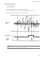
Hold mode and process ...........................................................................................................3-45
4
Setup software.............................................................................................. 4-1
4.1
4.2
4.3
4.4
4.5
4.6
5
vi
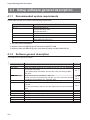
Setup software general description...................................................................................................... 4-2
4.1.1
Recommended system requirements .................................................................................. 4-2
4.1.2
Software general description ................................................................................................. 4-2
4.1.3
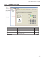
Software overview .................................................................................................................... 4-3
4.1.4
Menu............................................................................................................................................ 4-4
4.1.5
Tool bar ....................................................................................................................................... 4-4
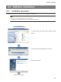
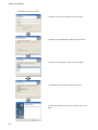
Software installation ................................................................................................................................ 4-5
4.2.1
Installation procedure ............................................................................................................. 4-5
4.2.2
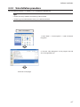
Uninstallation procedure ........................................................................................................ 4-7
4.2.3
Starting up setup software "UQ1 Navigator"...................................................................... 4-8
Storing / Loading setup parameters ..................................................................................................... 4-9
4.3.1
New project ................................................................................................................................ 4-9
4.3.2
Open project .............................................................................................................................. 4-9
4.3.3
Save project ............................................................................................................................... 4-9
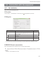
Connection with the sequencer........................................................................................................... 4-11
4.4.1
Set destination ........................................................................................................................ 4-11
4.4.2
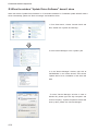
USB driver setting ................................................................................................................... 4-12
4.4.2
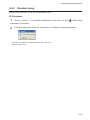
Readout setup ......................................................................................................................... 4-15
4.4.3
Write setup ............................................................................................................................... 4-16
Setup procedure ..................................................................................................................................... 4-17
4.5.1
Unit setup ................................................................................................................................. 4-17
4.5.2
Operation of setup screen .................................................................................................... 4-19
4.5.3
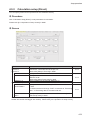
Calculation setup (Direct) ..................................................................................................... 4-21
4.5.4
Calculation setup (Application) ........................................................................................... 4-24
4.5.5
Sensor head setup .................................................................................................................. 4-28
4.5.6
Calibration setup .................................................................................................................... 4-30
4.5.7
I/O setup ................................................................................................................................... 4-32
4.5.8
Control output setup ............................................................................................................. 4-34
4.5.9
Storage setup .......................................................................................................................... 4-36
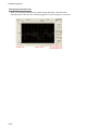
Confirming process ................................................................................................................................ 4-38
4.6.1
Measured result ...................................................................................................................... 4-38
4.6.2
Storage data ............................................................................................................................ 4-40
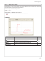
4.6.3
Waveform data ........................................................................................................................ 4-43
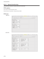
Trouble shooting ...................................................................................................... 5-1
5.1.1
Function ...................................................................................................................................... 5-2
5.1.2
Measurement ............................................................................................................................ 5-3
5.1.3
UQ1 shared memory , X/Y device .......................................................................................... 5-5
5.1.4
Setup software .......................................................................................................................... 5-7
5.1.5
Term ............................................................................................................................................. 5-8
6
Addendum .................................................................................................... 6-1
6.1.1
Cutoff frequency of the filter .........................................................................................6-2
vii
viii
1
General description
Feature
1.1 Feature
UQ1 series is interface unit that communicates with laser displacement sensor CD5/CD33 series and gets
the measurement result into “Shared Memory”.
Following are the features.
1) UQ1 communicates with CD5/CD33 series and gets measurement result automatically.
2) UQ1 series setups CD5/CD33 series, getting measurement result from CD5/CD33 series, calculation and
judges so rudder program is not needed for those process.
3) UQ1 series has control output terminal built-in so it works very fast, response time: 100us min., independently of PLC sequencer.
4) Setup software that programs UQ1 series at start up is available. Please contact the distributor.
5) You can connect up to two CD5/CD33 series sensor heads to a UQ1 series unit. It is cost effective and
also it’s easy to program calculation of thickness for example.
6) UQ1 series can communicate with other UQ1 series through “FIrST communication”, high speed infrared
communication, without using Q-bus.
1-2
Procedure summary
1.2 Procedure summary
1.2.1
Procedure summary up to start up
System configuration
→ Link: 1 General description
↓
Installing/Wiring of UQ1
→ Link: 2 System configuration
↓
Start up of UQ1
1.2.2
→ Link: 4 Setup software
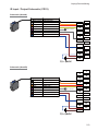
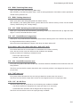
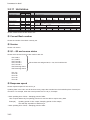
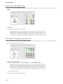
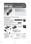
UQ1 series data flow
Data is processed in UQ1 series as following.
● In operation
CD5 series
Head A
CD5 series
Head B
Next UQ1
(slave side)
UQ1-01 1 2 3 4 5
IN 1 2
OUT 1 2
LNK
<<NEAR
FAR>>
JUDGE
ERR.
HEAD A
HAED B
CD5
HEAD
SDA
A
1
SDB
RDA
RDB
SDB
RDA
4
5
6
RDB
A
SYC OUT
B
7
1
9
SIG OUT
2
B
2
-
8
A
(SG)
1
TRG IN
UQ1-01
2
3
SDA
B
0
COM
C
D
+
E
12VDC
24VDC
80mA
F
UQ1-01 1 2 3 4 5
IN 1 2
OUT 1 2
LNK
<<NEAR
FAR>>
JUDGE
ERR.
HEAD A
HAED B
Input Data 1
Head A
Head B
Input Data 2
SDA
A
RDA
SDB
RDA
7
1
9
+ Offset
B
1
TRG IN
2
-
Judge source / Output Dat a
8
A
(SG)
Formula 1~3
5
A
SYC OUT
B
SIG OUT
2
Output Data 2
4
6
RDB
Output Data 1
2
3
SDA
UQ1
(master side )
0
1
SDB
RDB
B
Trigger input
: TRG IN1/2
: Y0A~Y0E
CD5
HEAD
COM
C
D
+
E
12VDC
24VDC
80mA
F
Output setup : Q1~5
Threshold
level
Control output
: SIG OUT1/2
: X01~X0F
* The data flow above shows about UQ1-01. CD33 series sensor heads will be used for UQ1-02.
1-3
Procedure summary
1
Input data
UQ1 series unit can get following data.
• Head A
: Measurement result of CD5/CD33 series sensor head A connected to UQ1-01/02
• Head B
: Measurement result of CD5/CD33 series sensor head B connected to UQ1-01/02
• Received data 1/2: Transmitted data specified at “Transmission Data setup” from the UQ1-01/02 connected to slave side.
Link: [2.1.1 FIrST communication]
2
Data calculation
Received data can be calculated according to the setup at “Formula 1~3 (shared memory
address 42~101)”.
Link: [3.2.3 Judge setup]
3
Control output
You can set threshold for the control output.
5 control outputs, Q1~Q5, are available.
You can specify which data to refer for the control output from Head A/B, Input Data 1/2 and
Formula 1~3.
You can add “offset” on specified measured result.
Tips
• When Sensor head or Input Data assigned in the calculation formula is not connected, "0" will be
applied.
• When you assign Sensor head that is not connected as the source of control output Q1~Q5, it will
cause the error X1B~X1F. Although, there won't be any error if you assign next UQ1 unit at slave
side as Input Data.
• When an error is occurred, you have to re-start up the power supply or set "Y16 error release" ON
to release the error.
• UQ1 series continues the procedure from getting measured result up to output every constant period.
This period is specified by "Process time, at shared memory address 327 (us)" rounding out every
100us. For example, when "Process time" is 140 (us), the constant period is 200 us.
• You can refer measured result of Sensor head A/B, Input Data 1/2, Calculation result 1~3 and control output Q1~Q5 through shared memory.
• FIrST communication will be done every updating period. When multiple UQ1 units are connected,
the data is transferred through the units every updating period so total delay will be updating period
* unit number connected to master unit.
1-4
Procedure summary
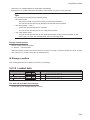
● Setup
Setup procedure is as follows.
1
Change setup parameters in shared memory
Setup parameters in shared memory are at following address.
Link: [3.1.4 Parameters in shared memory]
• Common setup parameters: address 0~126
• Parameters by Bank: address 128~159
Change these parameters accordingly.
Please refer “3 Process” for detailed of each parameter.
2
Activate Y (output device)
Activate Y (output device) accordingly.
Y10 Transfer setup parameters from shared memory to internal memory and CD5/CD33
Transfer setup parameters from shared memory address 0~127
to internal memory and CD5/CD33.
Switch the Bank according to the Bank number specified at shared memory address 102.
(Please refer “Y08 Switching Bank”)
X10 (input device: BUSY) will be ON while this process.
Y08 Switching Bank
Switching Bank
Readout setup data of the Bank number specified at shared memory address 102.
Transfer the parameter data corresponding from Bank memory into shared memory
address 128~159 and internal memory.
X12 (input device: BUSY) will be ON while this process.
Y11 Storing Bank setup
Store the setup data into specified Bank memory.
Transfer the setup data from shared memory address 128~159
into the Bank memory which number is specified at shared memory address 102.
X11 (input device: BUSY) will be ON while this process.
1-5
Procedure summary
Tips
• Data in the shared memory will be lost when the power is off. By activating Y10 and Y11, the ROM
in the unit will be updated with the data in the shared memory not only the internal memory in the
unit.
• When the unit is powered up without storing the data in the shared memory, it reboots with the data
in the ROM in the unit.
• While BUSY is activated, the unit stops getting data from CD5/CD33, calculating and output.
• Storage transfer start pointer (shared memory address 124, 125) is reflected without activating
any Y (output device). Bank number (shared memory address 102) is reflected by activating Y08
Switching Bank (output device). Please refer [3.2.6 Storage setup] about storage.
• While BUSY (X11~15) is activated, you won't be able to get correct data from the shared memory
corresponding to the BUSY.
1-6
Usable sequencer
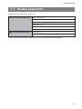
1.3 Usable sequencer
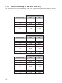
Usable sequencer (CPU unit) is as follows.
CPU unit can be used with UQ1
Basic model QCPU
High Performance model QCPU
Process CPU
Redundant CPU(*)
Universal model QCPU
Remote I/O station
CPU unit can not be used with
UQ1
C Controller unit
Safety CPU
* Can not install on main base unit and also can not proceed online module replacement.
1-7
Specifications
1.4 Specifications
Part number
Sampling period
UQ1-01
Min. 100μs
I/O points to occupy
32 points (I/O: Intelligent 32 points)
Communication method
Infrared
(between UQ1 units)
Terminal block
Usable wire
Usable Solderless
Core: 0.3 ~ 0.75mm2 (Outer diameter: Max. 2.8mm)
R1.25-3 without sleeve
terminal
Communication I/F Number of head
(between UQ1 and Protocol
CD5)
Baud rate
Cable
Cable extension
Control output
RS-422
921.6kbps
DOL-1212-G05M (5m sensor head cable)
Up to 50m using optional extension cable (unbundled)
Mode
NPN open collector
Output voltage
DC12-24V (±10%)
Output current
80mA (DC12-24V)
Residual voltage
Leak current
Trigger input
Max. 2 heads
Max. 1.0V
Max. 0.2mA
Protection
Over current protection circuitry
Logic
ON by connecting to GND (0V)
ON voltage
Max. 1.0V
OFF voltage
Min. 2.0V
Input impedance
Function
Approximately 10kΩ
Setup sensor head, Control output, Calculation, Hold function
Filter function, Bank setup, Storage function
EEPROM overwriting limit
Max. 1000,000 times for same memory area
DC5V current consumption
Max. 0.5A
Noise tolerance
500Vp-p (simulator), Noise width: 1μs
Fast transient noise 1kV (IEC 61000-4-4)
Insulation resistance
Min. 10MΩ (insulation resistance meter)
Protection category
IP2X
Operating Temp. / Humid.
-10 ~ +55℃ / 35 ~ 85%RH (non condensation)
Storage Temp. / Humid.
-20 ~ +70℃ / 35 ~ 85%RH (non condensation)
Vibration resistance
Dimensions
Weight
1-8
10 ~ 55Hz Double amplitude 1.5mm 2 hours per X, Y, Z axis
98(H) * 27.4(W) * 90(D) [mm]
Approximately 150g
Specifications
Part number
Sampling period
UQ1-02
Min. 100μs
I/O points to occupy
32 points (I/O: Intelligent 32 points)
Communication method
Infrared
(between UQ1 units)
Terminal block
Usable wire
Usable Solderless
Core: 0.3 ~ 0.75mm2 (Outer diameter: Max. 2.8mm)
R1.25-3 without sleeve
terminal
Communication I/F Number of head
(between UQ1 and Protocol
CD33)
Baud rate
Control output
RS-422
256kbps
Mode
NPN open collector
Output voltage
DC12-24V (±10%)
Output current
80mA (DC12-24V)
Residual voltage
Leak current
Trigger input
Max. 2 heads
Max. 1.0V
Max. 0.2mA
Protection
Over current protection circuitry
Logic
ON by connecting to GND (0V)
ON voltage
Max. 1.0V
OFF voltage
Min. 2.0V
Input impedance
Function
Approximately 10kΩ
Setup sensor head, Control output, Calculation, Hold function
Filter function, Bank setup, Storage function
EEPROM overwriting limit
Max. 1000,000 times for same memory area
DC5V current consumption
Max. 0.5A
Noise tolerance
500Vp-p (simulator), Noise width: 1μs
Fast transient noise 1kV (IEC 61000-4-4)
Insulation resistance
Min. 10MΩ (insulation resistance meter)
Protection category
IP2X
Operating Temp. / Humid.
-10 ~ +55℃ / 35 ~ 85%RH (non condensation)
Storage Temp. / Humid.
-20 ~ +70℃ / 35 ~ 85%RH (non condensation)
Vibration resistance
Dimensions
Weight
10 ~ 55Hz Double amplitude 1.5mm 2 hours per X, Y, Z axis
98(H) * 27.4(W) * 90(D) [mm]
Approximately 150g
* Cable for connector type CD33 are available; DOL-1208-G02M/5M (2m/5m)
1-9
Specifications
1-10
2
System installation
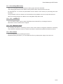
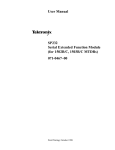
System installation
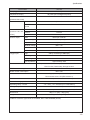
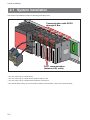
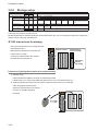
2.1 System installation
UQ1 series are installed on Q Bus as following example picture.
Communication with QCPU
through Q Bus
UQ
1
01
1 2
IN
3 4
1 2
5
OUT
1 2
LN
K
<<
JUDG
E
ERR
NE
AR
HEA
FAR
>>
DA
HE A
DB
UQ
1
01
1 2
IN
3 4
1 2
5
OU
T1
2
LN
K
<<
JUDG
E
ERR
NE
AR
HEAD
A
FA
R >>
HE AD
B
UQ
1
01
IN
1 2
3 4
1 2
5
OU
T1
2
LN
K
<<
NE
AR
FA
R >>
JUDG
E
UQ
1 0
1
ERR
IN
HEA
DA
OUT
HEA
DB
1 2
1 2
3 4
5
12
JUDG
E
LN
K
<<
ERR
NE
AR
HE AD
FAR
>>
A
HEAD
B
FIrST communication
(between UQ1 units)
- You can connect up to 4 UQ1 series.
- You can connect up to 2 CD5 sensor heads to UQ1-01 unit.
- You can connect up to 2 CD33 sensor heads to UQ1-02 unit.
- UQ1 series utilize 2 ways of communication “Q Bus communication” and “FIrST communication”.
2-2
System installation
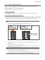
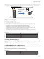
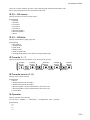
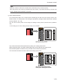
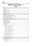
2.1.1
FIrST communication
UQ1 units can communicate through “FIrST communication” utilizing infrared without using Q Bus.
● Advantages of “FIrST communication”
Advantages of “FIrST communication” are as follow.
<1> Fast communication
It works independently of the Q Bus so it can let UQ1 units communicate in 100μs in the shortest.
<2> Calculation using data from other QU1 unit
You can use measurement result from other UQ1 units installed next to the UQ1 unit (master side) for
calculation. Up to 2 CD5/CD33 sensor heads can be connected to a unit and utilize more than 3 measurement result through “FIrST communication” for calculation for example getting average of them.
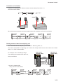
Tips
<1>
“FIrST communication” is available only between adjacent UQ1 units.
UQ1 units must be installed at adjacent Bus.
<Good>
<No Good>
Installed adjacently
"FIrST" is available
There is another unit
between UQ1 units
UQ1-01
UQ1-01
1 2 3 4 5
JUDG E
ERR.
HEAD A
HAED B
IN 1 2
O UT 1 2
LNK
<<NEAR
CD5
HEAD
<<NEAR
A
B
SYC O UT
SIG O UT
2
SIG O UT
12VDC
<2>
SIG O UT
B
SIG O UT
1
2
1
1
TRG IN
2
12VDC
A
SYC O UT
1
2
1
TRG IN
2
RDB
A
B
1
2
1
TRG IN
SDB
RDA
SYC O UT
B
1
SDA
RDB
A
A
B
No unit or another
unit is installed.
RDA
B
RDA
RDB
RDB
SDB
RDB
SDB
RDA
SYC O UT
SDA
A
SDA
B
FAR>>
CD5
HEAD
RDA
SDB
RDA
<<NEAR
RDB
SDA
SDB
JUDG E
ERR.
HEAD A
HAED B
LNK
FAR>>
SDB
RDA
1 2 3 4 5
IN 1 2
O UT 1 2
SDA
A
RDB
SDA
B
<<NEAR
CD5
HEAD
SDB
RDA
RDB
JUDG E
ERR.
HEAD A
HAED B
LNK
SDA
SDB
UQ1-01
1 2 3 4 5
IN 1 2
O UT 1 2
FAR>>
CD5
HEAD
SDA
A
JUDG E
ERR.
HEAD A
HAED B
LNK
FAR>>
UQ1-01
1 2 3 4 5
IN 1 2
O UT 1 2
TRG IN
2
12VDC
2
12VDC
Data is transferred only from slave side (far side from QCPU) to master side (near side
of QCPU).
<3>
Setup of data transmission is done at slave side.
Master side (near side of QCPU) unit treats the data as “Input data 1” and “Input data 2” because it doesn’t know transmission setup.
- “FIrST communication” is done every updating period.
- Up to 4 UQ1 units can be connected and data is transferred from the unit at far side to near
side of QCPU one by one. Then, it delays for total cycle of updating period.
2-3
Display/Terminal/Wiring
2.2 Display/Terminal/Wiring
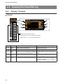
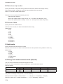
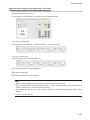
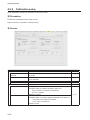
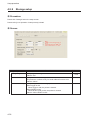
2.2.1
Display / Terminal
● Display
UQ1-01 1 2 3 4 5
IN 1 2
OUT 1 2
LNK
<<NEAR
FAR>>
CD5
HEAD
0
SDA
A
1
SDB
RDA
3
SDA
4
SDB
5
RDA
6
RDB
A
SYC OUT
B
7
1
9
SIG OUT
2
A
B
1
TRG IN
C
2
D
COM
E
+
2-4
②
IN 1 2
OUT1 2
③
LNK
<<N
EAR
FAR>>
JUDGE
ERR.
HEADA
HEADB
④
⑤
⑥
Hole for FIrST communication
Please don’t cover or contaminate this part.
Please refer [ 2.1.1 FIrST communication
F
12VDC
24VDC
80mA
No.
UQ1-01 1 2 3 4 5
8
(SG)
-
①
2
RDB
B
JUDGE
ERR.
HEAD A
HAED B
Item
Description
Note
1
IN1/2
Status of the terminal IN1/2
Orange when it's ON
2
OUT1/2
Status of the terminal OUT1/2
Orange when it's ON
3
LNK
Status of FIsT communication between Orange when the communication is
the unit and next unit at slave side.
made
4
JUDGE
Status of the control output Q1~Q5.
5
ERR
Error status of the control output Q1~Q5. Red when it's error. You can release the
error by re-booting the unit or setting Error release Y16 ON.
Orange when the control output is ON
(X0B ~ X0F = 0)
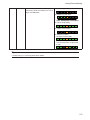
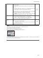
Display/Terminal/Wiring
6
HEAD A/B
Show distance that Head A and B are <1> Measuring center (±10%)
measuring. When the distance is out of
range, all LEDs blink.
<2> Measuring near side
LEDs ON depends on distance
<3> Out of range (blink)
<4> Laser is OFF (blink)
<5> Monitoring Wave
- No light received (ON)
- LED at the position of light peak
is OFF
Tips
• Please refer [5.1.1 Process] about other status.
2-5
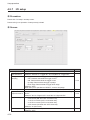
Display/Terminal/Wiring
● Terminal
UQ1-01 1 2 3 4 5
IN 1 2
OUT 1 2
LNK
<<NEAR
FAR>>
JUDGE
ERR.
HEAD A
HAED B
CD5
HEAD
1
SDA
A
SDB
RDA
RDB
SDA
B
SDB
RDA
RDB
A
SYC OUT
B
SIG OUT
2
1
2
3
4
5
6
7
8
9
10
11
12
13
(SG)
4
6
8
10
12
14
14
1
TRG IN
2
-
1
2
COM
+
15
16
16
17
18
3
5
7
9
11
13
15
17
18
12VDC
24VDC
80mA
UQ1 Terminal block
No.
Terminal
1 [Head A] SDA
2
4
[Head A] SDB
3 [Head A] RDA
[Head A] RDB
5 [Head B] SDA
6
7
8
9
10
11
12
13
14
15
16
17
18
2-6
Function
Head A send (+)
Note
RS422 signals for Head A
(GND to be connected to 13 SG.)
Head A send (-)
Head A receive (+)
Head A receive (-)
Head B send (+) RS422 signals for Head B
(GND to be connected to 13 SG.)
[Head B] SDB
Head B send (-)
[Head B] RDA Head B receive (+)
[Head B] RDB Head B receive (-)
Sync Out A
Head A Sync out For preventing cross talk
Sync Out B
Head B Sync out For preventing cross talk
Signal Out 1
Control out [1]
Signal Out 2
Control out [2]
SG
Signal Ground
GND of RS422 to be connected
Trigger In 1
Trigger in [1]
Trigger In 2
Trigger in [2]
COM(SG)
I/O common (-)
GND of [Sync Out], [Signal Out], [Trigger In]
to be connected
Plus line of DC12~24V power supply to be connected
12~24V
I/O power (+)
(No.17 and 18 is connected internally on PCB)
12~24V
I/O power (+)
Display/Terminal/Wiring
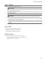
2.2.2
Wiring
Please read this chapter carefully before wiring.
Warning
Please confirm that the source of power supply is shut down before wiring to prevent electric
shock and damage of the product.
Please confirm that the cover is fixed over terminal block after wiring and before power on to
prevent electric shock.
Caution
To prevent malfunction and storing wrong data because of noise, please keep following.
1) Please confirm that communication lines are not banded with power line and high voltage
line to prevent noise and surge induction.
2) Please confirm that the grounding of the cable shield line is done at a ground point of sequencer side. Please don't connect the ground line of high power line at the same grounding point.
● Procedure
■
Shut down the power supply of sequencer.
■
Wire CD5 sensor to the unit (UQ1-01).
■
Wire CD33 sensor to the unit (UQ1-02).
● Terminal block
■
M3 screws are used for terminal block of UQ1 series.
Please use solder less terminal R1.25-3 (without sleeve).
Tightening torque : 0.5 ~ 0.8N・m
2-7
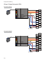
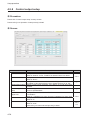
Display/Terminal/Wiring
● Input / Output Schematic (CD5)
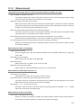
Schematic (Head A)
Cable color
Description
Black(narrow) RS422 input(+)
Orange
RS422 input(-)
Red
RS422 output(+)
Yellow
RS422 output(-)
White
Laser OFF input
Gray
Sync input
Brown
Power supply 12V~24V(±10%)
Blue
Power supply 0V
Black(thick)
Shield (0V)
1
2
4
N.C.
6
8
3
5
7
9
10
11
12
13
14
15
16
17
18
12~24VDC
Schematic (Head B)
1
2
Cable color
Description
4
Black(narrow) RS422 input(+)
Orange
RS422 input(-)
Red
RS422 output(+)
Yellow
RS422 output(-)
White
Laser OFF input
Gray
Sync input
Brown
Power supply 12V~24V(±10%)
Blue
Power supply 0V
Black(thick)
Shield (0V)
6
N.C.
8
3
5
7
9
10
11
12
13
14
15
16
17
18
12~24VDC
2-8
Display/Terminal/Wiring
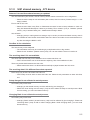
● Input / Output Schematic (CD33)
Schematic (Head A)
Color
Function
Black (narrow) RS422 Receive +
White
RS422 Receive -
Orange
RS422 Send +
Pink
RS422 Send -
Purple
Control output Q2
Gray
MF
Brown
Power 12 V~24 V(±10% )
Blue
Power 0 V
1
2
4
No contact
6
8
3
5
7
9
10
11
12
13
14
15
16
17
18
12~24 VDC
Schematic (Head B)
1
2
Color
4
Function
Black(narrow) RS422 Receive +
White
RS422 Receive -
Orange
RS422 Send +
Pink
RS422 Send -
Purple
Control output Q2
Gray
MF
Brown
Power 12 V~24 V(±10%)
Blue
Power 0 V
6
8
No contact
3
5
7
9
10
11
12
13
14
15
16
17
18
12~24 VDC
2-9
Display/Terminal/Wiring
● Grounding
- Please ground UQ1 series as following.
- Ground each equipment individually as much as available.
- Grounding impedance should be less than 100Ω.
- If you couldn’t ground equipment individually, please ground to common point.
UQ1
Other
equipment
Individual grounding
(the best)
UQ1
Other
equipment
One point grounding
(OK)
- Please use thicker than AWG14(2mm2) for grounding line.
- Please shorten the grounding line as much as possible.
2-10
UQ1
Other
equipment
Just connecting to ground
(No good)
Display/Terminal/Wiring
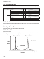
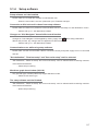
2.2.3
Input / Output schematic
● Input schematic
Level Shifter
Internal circuitry
Internal Power (+)
Trigger IN1
Trigger IN2
Tips
• Function of the input (Trigger IN1/2) is defined at shared memory address 116~118.
• Input level is fetched every updating period of UQ1 independent of sequencer scan timing.
Internal circuitry
● Output schematic
Signal OUT 1
Signal OUT 2
COM
Tips
• Function of the out (Signal OUT1/2) is defined at shared memory 113~115.
• Output is updated every updating period of UQ1-01 independent of sequencer scan timing.
2-11
Display/Terminal/Wiring
2-12
3
Function
Shared memory and X/Y device
3.1 Shared memory and X/Y device
UQ1 series X/Y device table and function are as follows. Please refer chapter 2 about outline.
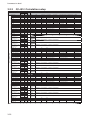
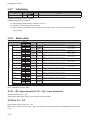
3.1.1
X/Y device table
Address of X/Y device is described in hexadecimal.
X (Input)
description
Y (Output)
decimal
hex.
X00
X00
Unit ready (reserved)
Y00
Y00
Yes Zero reset Q1
X01
X01
Q1 Upper (0= below "upper", 1= "upper" and over) Y01
Y01
Yes Zero reset Q2
X02
X02
Q1 Lower (0= over "lower", 1= "lower" and under)
Y02
Y02
Yes Zero reset Q3
X03
X03
Q2 Upper
Y03
Y03
Yes Zero reset Q4
X04
X04
Q2 Lower
Y04
Y04
Yes Zero reset Q5
X05
X05
Q3 Upper
Y05
Y05
Yes
X06
X06
Q3 Lower
Y06
Y06
Yes
X07
X07
Q4 Upper
Y07
Y07
Yes
X08
X08
Q4 Lower
Y08
Y08
Switching Bank
X09
X09
Q5 Upper
Y09
Y09
RESET
X10
X0A Q5 Lower
Y10
Y0A
Trigger IN A
X11
X0B Q1 judge (1=OK)
Y11
Y0B
X12
X0C Q2 judge (1=OK)
Y12 Y0C
Trigger IN Calculation 1
X13
X0D Q3 judge (1=OK)
Y13 Y0D
Trigger IN Calculation 2
X14
X0E Q4 judge (1=OK)
Y14
Y0E
Trigger IN Calculation 3
X15
X0F
Q5 judge (1=OK)
Y15
Y0F
Getting Data stored
X16
X10
BUSY: Over writing Common setup
Y16
Y10
Over writing common setup
X17
X11
BUSY: Over writing Bank setup
Y17
Y11
Over writing Bank setup
X18
X12
BUSY: Switching Bank setup
Y18
Y12
LASER OFF A (0=ON,1=OFF)
X19
X13
BUSY: Getting data stored
Y19
Y13
LASER OFF B (0=ON,1=OFF)
X20
X14
BUSY: Switching Head A monitoring mode Y20
Y14
Head A Waveform mode *2
X21
X15
BUSY: Switching Head B monitoring mode Y21
Y15
Head B Waveform mode *2
X22
X16
Head A out of range alarm
Y16
Error release
X23
X17
Head B out of range alarm
Y23
Y17
X24
X18
Head A connection error *1
Y24
Y18
X25
X19
Head B connection error *1
Y25
Y19
X26
X1A FIrST data error *1
Y26
Y1A
X27
X1B Q1 Error (no target sensor head) *1
Y27
Y1B
X28
X1C Q2 Error (no target sensor head) *1
Y28 Y1C
X29
X1D Q3 Error (no target sensor head) *1
Y29 Y1D
X30
X1E Q4 Error (no target sensor head) *1
Y30
Y1E
X31
X1F
Y31
Y1F
Q5 Error (no target sensor head) *1
decimal
Y22
hex.
Int.
description
Trigger IN B
*1 These errors can be released only by re-starting up the power supply or setting “Y16 error release” ON.
*2 Can be used only with specular type for UQ1-02.
3-2
Shared memory and X/Y device
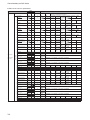
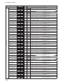
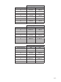
3.1.2
Shared memory table
Address of the shared memory is described in decimal.
Shared memory in the address 0~30 are different between UQ1-01 and UQ1-02.
■ UQ1-01
Address
Hex.
Decimal
Measurement target
0000h
0
Diffuse / Specular
0001h
1
Laser power
0002h
2
Sensitivity
0003h
3
Threshold for detecting peak 0004h
4
Shift
0005h
5
0006h
6
Span
0007h
7
0008h
8
Moving average number
0009h
9
Item
Sensor head A
setup
Over written by
Y10=1
Sensor head B
setup
Alarm processing
Sampling period
Reserved
Reserved
Measurement target
Diffuse / Specular
Laser power
Sensitivity
Threshold for detecting peak
Shift
Span
Over written by
Y10=1
Sensor head A/B
setup
Moving average number
000Ah
000Bh
000Ch
000Dh
000Eh
000Fh
0010h
0011h
0012h
0013h
0014h
0015h
0016h
0017h
Alarm processing
0018h
Sampling period
0019h
Reserved
001Ah
Reserved
001Bh
Cross talk prevention func- 001Ch
tion
filter choice
001Dh
Cutoff frequency
001Eh
10
11
12
13
14
15
16
17
18
19
20
21
22
23
Default
0
0
5
11
0
0
Parameters
0=Surface
0=Diffuse
0=OFF
0=Min.
0~14
LOW
HI
LOW
HI
0=1 time
1=2 times
2=4 times
8=256 times
9=512 times
A=1024 times B=2048 times
C=4096 times
0
0
0=Clamp
0=100us
1=Hold
1=200us
2=400us
4=1600us
0
0
5
11
0
0
0=Surface
0=Diffuse
0=OFF
0=Min.
0~14
LOW
HI
LOW
HI
0=1 time
1=Flip side 2= Glass thickness
1=2 times
2=4 times
8=256 times
9=512 times
A=1024 times B=2048 times
C=4096 times
2=400us
4=1600us
2710h
(10000)
8
2710h
(10000)
8
1=Flip side 2= Glass thickness
3= Glass gap
1=Specular
1~5 (5:MAX.)
1~10
11=AUTO
15=AUTO
-50000000 b~ +50000000
(Depends on the sensor head. Please refer [3.2.1 Sensor head setup])
0 ~ 9C3Fh (0 ~ 39999) Example: 10000 means Span=1.0000
3=8 times
3=800us
4=16 times
5=32 times 6=64 times 7=128 times
5=3200us
6=AUTO
3= Glass gap
1=Specular
1~5 (5:MAX.)
1~10
11=AUTO
15=AUTO
-50000000 b~ +50000000
(Depends on the sensor head. Please refer [3.2.1 Sensor head setup])
0 ~ 9C3Fh (0 ~ 39999) Example: 10000 means Span=1.0000
24
25
26
27
28
0
0
0=Clamp
0=100us
1=Hold
1=200us
0
0=OFF
1=ON
29
30
0
0
0=OFF
0=High
1=High pass filter
~ 7= Low
3=8 times
3=800us
4=16 times
5=32 times 6=64 times 7=128 times
5=3200us
6=AUTO
1=Low pass filter
■ UQ1-02
Item
Sensor head A
setup
Over written by
Y10=1
Sensor head B
setup
Over written by
Y10=1
Reserved
Reserved
Reserved
Measurement target
Reserved
Laser
Reserved
Reserved
Shift
Span
Moving average number
Alarm processing
Sampling period
Reserved
Reserved
Measurement target
Reserved
Laser
Reserved
Reserved
Shift
Span
Moving average number
Alarm processing
Sampling period
Reserved
Reserved
Address
Hex.
Decimal
0000h
0
0001h
1
0002h
2
0003h
3
0004h
4
0005h
5
0006h
6
0007h
7
0008h
8
0009h
9
000Ah
10
000Bh
11
000Ch
12
000Dh
13
000Eh
14
000Fh
15
0010h
16
0011h
17
0012h
18
0013h
19
0014h
20
0015h
21
0016h
22
0017h
23
0018h
24
0019h
25
001Ah
26
001Bh
27
001Ch
28
001Dh
29
001Eh
30
Default
Parameters
0
0= Peak
1= Surface 2=Flip side 3= Glass thickness
1
0=OFF
1=ON
0
1
0
0
LOW
-50000000 b~ +50000000
(Depends on the sensor head. Please refer [3.2.1 Sensor head setup])
HI
LOW
0 ~ 9C3Fh (0 ~ 39999) Example: 10000 means Span=1.0000
HI
0= 1 time 1=16 times 2=64 times
0=Clamp
1=Hold
0=500us (250mm type: 750us)
1=1000us 2=1500us 3=2000us
0
0= Peak
1= Surface 2=Flip side 3= Glass thickness
1
0=OFF
1=ON
0
LOW
-50000000 b~ +50000000
(Depends on the sensor head. Please refer [3.2.1 Sensor head setup])
HI
LOW
0 ~ 9C3Fh (0 ~ 39999) Example: 10000 means Span=1.0000
HI
0= 1 time 1=16 times 2=64 times
0=Clamp
1=Hold
0=500us (250mm type: 750us)
1=1000us 2=1500us 3=2000us
2710h
(10000)
2710h
(10000)
1
0
0
3-3
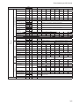
Shared memory and X/Y device
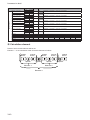
■ UQ1-01/02 common parameters
Item
UQ1 setup
Over written
by Y10=1
Q1~Q5 setup
High speed mode
Address
Hex.
Dec.
001Fh
31
Default
Parameters
0
0=OFF
1=ON
(It doesn’t do averaging when this parameter is 1=ON. “Auto average” and
“Average” in measured result will be “0”.)
2= Formula 3= Formula 4= Formula 5= Receiving 6= Receiving 7= None
data 1
data 2
1
2
3
2= Peak
3= Bottom 4= Peak to 5= Average
Peak
2= Formula 3= Formula 4= Formula 5= Receiving 6= Receiving 7= None
data 1
data 2
1
2
3
2= Peak
3= Bottom 4= Peak to 5= Average
Peak
2= Formula 3= Formula 4= Formula 5= Receiving 6= Receiving 7= None
data 1
data 2
1
2
3
2= Peak
3= Bottom 4= Peak to 5= Average
Peak
2= Formula 3= Formula 4= Formula 5= Receiving 6= Receiving 7= None
data 1
data 2
1
2
3
2= Peak
3= Bottom 4= Peak to 5= Average
Peak
2= Formula 3= Formula 4= Formula 5= Receiving 6= Receiving 7= None
data 1
data 2
1
2
3
2= Peak
3= Bottom 4= Peak to 5= Average
Peak
3= Receiving 4= Receiving 5= Fixed
2=B
data 1
data 2
value 1-1
3= Receiving 4= Receiving 5= Fixed
2=B
data 1
data 2
value 1-2
3= Receiving 4= Receiving 5= Fixed
2=B
data 1
data 2
value 1-3
3= Receiving 4= Receiving 5= Fixed
2=B
data 1
data 2
value 1-4
3= Receiving 4= Receiving 5= Fixed
2=B
data 1
data 2
value 1-5
Q1 Source
0020h
32
0
0=A
1=B
Q1 Hold
0021h
33
0
0= None
1= Sample
Q2 Source
0022h
34
1
0=A
1=B
Q2 Hold
0023h
35
0
0= None
1= Sample
Q3 Source
0024h
36
7
0=A
1=B
Q3 Hold
0025h
37
0
0= None
1= Sample
Q4 Source
0026h
38
7
0=A
1=B
Q4 Hold
0027h
39
0
0= None
1= Sample
Q5 Source
0028h
40
7
0=A
1=B
Q5 Hold
0029h
41
0
0= None
1= Sample
Formula source 1-1
002Ah
42
0
0= None
1=A
Formula source 1-2
002Bh
43
0
0= None
1=A
Formula source 1-3
002Ch
44
0
0= None
1=A
Formula source 1-4
002Dh
45
0
0= None
1=A
Formula source 1-5
002Eh
46
0
0= None
1=A
Reserved
002Fh
Fixed value for Formula 0030h
source 1-1
0031h
Fixed value for Formula 0032h
source 1-2
0033h
Fixed value for Formula 0034h
source 1-3
0035h
Fixed value for Formula 0036h
source 1-4
0037h
Fixed value for Formula 0038h
source 1-5
0039h
Operator 1-1
003Ah
Operator 1-2
003Bh
Operator 1-3
003Ch
Operator 1-4
003Dh
Formula source 2-1
003Eh
47
48
49
50
51
52
53
54
55
56
57
58
59
60
61
62
0
LOW
HI
LOW
HI
LOW
HI
LOW
HI
LOW
HI
0= +
0= +
0= +
0= +
0= None
080000000 h (-2147483648) ~ 7FFFFFFFh (2147483647)
0
0
0
0
0
0
0
0
0
080000000 h (-2147483648) ~ 7FFFFFFFh (2147483647)
080000000 h (-2147483648) ~ 7FFFFFFFh (2147483647)
080000000 h (-2147483648) ~ 7FFFFFFFh (2147483647)
080000000 h (-2147483648) ~ 7FFFFFFFh (2147483647)
1= 1= 1= 1= 1=A
2= *
2= *
2= *
2= *
2=B
3= ÷
3= ÷
3= ÷
3= ÷
3= Receiving 4= Receiving
data 1
Formula source 2-2
003Fh
63
0
0= None
1=A
2=B
Formula source 2-3
0040h
64
0
0= None
1=A
2=B
Formula source 2-4
0041h
65
0
0= None
1=A
2=B
Formula source 2-5
0042h
66
0
0= None
1=A
2=B
Reserved
0043h
Fixed value for Formula 0044h
source 2-1
0045h
Fixed value for Formula 0046h
source 2-2
0047h
Fixed value for Formula 0048h
source 2-3
0049h
Fixed value for Formula 004Ah
source 2-4
004Bh
Fixed value for Formula 004Ch
source 2-5
004Dh
Operator 2-1
004Eh
Operator 2-2
004Fh
Operator 2-3
0050h
Operator 2-4
0051h
67
68
69
70
71
72
73
74
75
76
77
78
79
80
81
3= Receiving 4= Receiving
data 1
3-4
0
0
0
0
0
0
0
data 2
3= Receiving 4= Receiving
data 1
0
data 2
3= Receiving 4= Receiving
data 1
LOW
HI
LOW
HI
LOW
HI
LOW
HI
LOW
HI
0= +
0= +
0= +
0= +
data 2
3= Receiving 4= Receiving
data 1
0
data 2
data 2
5= Fixed
value 2-1
5= Fixed
value 2-2
5= Fixed
value 2-3
5= Fixed
value 2-4
5= Fixed
value 2-5
080000000 h (-2147483648) ~ 7FFFFFFFh (2147483647)
080000000 h (-2147483648) ~ 7FFFFFFFh (2147483647)
080000000 h (-2147483648) ~ 7FFFFFFFh (2147483647)
080000000 h (-2147483648) ~ 7FFFFFFFh (2147483647)
080000000 h (-2147483648) ~ 7FFFFFFFh (2147483647)
1= 1= 1= 1= -
2= *
2= *
2= *
2= *
3= ÷
3= ÷
3= ÷
3= ÷
Shared memory and X/Y device
Item
Formula source 3-1
Address
Hex.
Dec.
0052h
82
Default
0
Parameters
0= None
1=A
2=B
3= Receiving 4= Receiving
data 1
Formula source 3-2
0053h
83
0
0= None
1=A
2=B
Formula source 3-3
0054h
84
0
0= None
1=A
2=B
Formula source 3-4
0055h
85
0
0= None
1=A
2=B
Formula source 3-5
0056h
86
0
0= None
1=A
2=B
Reserved
0057h
Fixed value for Formula 0058h
source 3-1
0059h
Fixed value for Formula 005Ah
source 3-2
005Bh
Fixed value for Formula 005Ch
source 3-3
005Dh
Fixed value for Formula 005Eh
source 3-4
005Fh
Fixed value for Formula 0060h
source 3-5
0061h
Operator 3-1
0062h
Operator 3-2
0063h
Operator 3-3
0064h
Operator 3-4
0065h
Bank number
0066h
Hold mode
0067h
Hysteresis
0068h
0069h
ON delay
006Ah
OFF delay
006Bh
One shot
006Ch
FIrST Transmit data 1 006Dh
setup
FIrST Transmit data 1 006Eh
Hold
FIrST Transmit data 2 006Fh
setup
FIrST Transmit data 2 0070h
Hold
Signal Out 1
0071h
Signal Out 2
0072h
Signal Out logic
0073h
87
88
89
90
91
92
93
94
95
96
97
98
99
100
101
102
103
104
105
106
107
108
109
Trigger timing of data 0074h
sampling
Trigger IN 1
0075h
Trigger IN 2
3= Receiving 4= Receiving
data 1
Q1 Q5 / Calculation setup
Etc.
Data storing
Input setup
Output setup
Over written
by Y10=1
Initialize
data 2
3= Receiving 4= Receiving
data 1
UQ1 Setup
data 2
3= Receiving 4= Receiving
data 1
data 2
3= Receiving 4= Receiving
data 1
0
data 2
data 2
5= Fixed
value 3-1
5= Fixed
value 3-2
5= Fixed
value 3-3
5= Fixed
value 3-4
5= Fixed
value 3-5
110
0
111
1
112
0
113
114
115
0
1
0
116
0
117
0
0076h
118
1
Data store skip number
Source of data
0077h
0078h
119
120
0
0
Hold mode
0079h
121
0
Pointer clear timing
007Ah
122
1
LOW
080000000 h (-2147483648) ~ 7FFFFFFFh (2147483647)
HI
LOW
080000000 h (-2147483648) ~ 7FFFFFFFh (2147483647)
HI
LOW
080000000 h (-2147483648) ~ 7FFFFFFFh (2147483647)
HI
LOW
080000000 h (-2147483648) ~ 7FFFFFFFh (2147483647)
HI
LOW
080000000 h (-2147483648) ~ 7FFFFFFFh (2147483647)
HI
0= +
1= 2= *
3= ÷
0= +
1= 2= *
3= ÷
0= +
1= 2= *
3= ÷
0= +
1= 2= *
3= ÷
0 ~ 59 = Bank 0 ~ 59
0 = Auto (data clear when RESET) 1 = Normal (data clear when sampling starts)
LOW
0 ~ 7FFFFFFFh (2147483647)
HI
0= None
1 ~ 0FFFFh (65535) ms
* Reflect to Signal Out 1, 2 , X device
0= None
1 ~ 0FFFFh (65535) ms
* Reflect to Signal Out 1, 2 , X device
0=OFF
1=ON
* Reflect to Signal Out 1, 2 , X device
0= Head A 1= Head B 2=Formula 3=Formula 4=Formula 5= None
1
2
3
0= None
1=Sample 2= Peak
3= Bottom 4= Peak to 5=Average
Peak
0= Head A 1= Head B 2=Formula 3=Formula 4=Formula 5= None
1
2
3
0= None
1=Sample 2= Peak
3= Bottom 4= Peak to 5=Average
Peak
0=Q1
1=Q2
2=Q3
3=Q4
4=Q5
* ON when out side of threshold
0=Q1
1=Q2
2=Q3
3=Q4
4=Q5
* ON when out side of threshold
0= All
1=1 is
2=2 is
3= All
normal
reverse
reverse
reverse
0= OFF
1= ON
2= Up edge
3= Down edge
* RESET effects at up
edge only
0= RESET 1= Head A 2= Head B 3=Formula 4=Formula 5=Formula
1
2
3
0= RESET 1= Head A 2= Head B 3=Formula 4=Formula 5=Formula
1
2
3
0=No skip 1 ~ 0FFFFh (65535)
0=Q1
1=Q2
2=Q3
3=Q4
4=Q5
5=Head A 6=Head B 7=Formula
1
8= Formula 2
9= Formula 3
* Q1~Q5 will be added its offset.
0= None
1= Sample 2= Peak
3=Bottom 4= Peak to 5=Average * Effective when the
Peak
source of data is Head
A ~ Formula 3 (5~9)
0=When Trigger is ON 1=When RESET is ON
Pointer end control
Storage transfer start
pointer
007Bh
007Ch
123
124
1
0
0=Stop
LOW
007Dh
125
Reserved
Initialize
007Eh
007Fh
126
127
0
0
0
0
0
0
0
0
0
0
0
0
0
0
0
HI
0
0101h
1=Continue from start
Start pointer number (0 ~ 245928) of the internal storage memory for transferring to
shared memory. 262144 (14Eh~7FFDh) totally (every 16216). This is effective immediately after updating.
* Initialize by rebooting after setting this parameter "0"and Y10 as "1".
3-5
Shared memory and X/Y device
■ Measurement result
Address
Hex.
Dec.
Q1 Upper threshold
0080h
128
0081h
129
Q1 Lower threshold
0082h
130
0083h
131
Q2 Upper threshold
0084h
132
0085h
133
Q2 Lower threshold
0086h
134
0087h
135
Q3 Upper threshold
0088h
136
0089h
137
Q3 Lower threshold
008Ah
138
008Bh
139
Q4 Upper threshold
008Ch
140
008Dh
141
Q4 Lower threshold
008Eh
142
008Fh
143
Q5 Upper threshold
0090h
144
0091h
145
Q5 Lower threshold
0092h
146
0093h
147
Q1 Offset
0094h
148
0095h
149
Q2 Offset
0096h
150
0097h
151
Q3 Offset
0098h
152
0099h
153
Q4 Offset
009Ah
154
009Bh
155
Q5 Offset
009Ch
156
009Dh
157
Reserved
009Eh
158
Reserved
009Fh
159
Q1
00A0h
160
00A1h
161
Q2
00A2h
162
00A3h
163
Q3
00A4h
164
00A5h
165
Q4
00A6h
166
00A7h
167
Q5
00A8h
168
00A9h
169
Head A Center stand off 00AAh
170
00ABh
171
Head B Center stand off 00ACh
172
00ADh
173
Reserved
00AEh
174
Reserved
00AFh
175
Head A
00B0h
176
00B1h
177
Head A Sample Hold
00B2h
178
00B3h
179
Head A Auto Peak Hold 00B4h
180
00B5h
181
Head A Peak Hold
00B6h
182
00B7h
183
Head A auto Bottom Hold 00B8h
184
00B9h
185
Head A Bottom Hold
00BAh
186
00BBh
187
Head A Auto Peak to
00BCh
188
Peak Hold
00BDh
189
Head A Peak to Peak
00BEh
190
Hold
00BFh
191
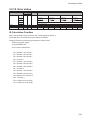
Bank setup
Center stand off
Q1~Q5 result
Over written
by Y11=1
Threshold / Offset
Item
Measurement result
Result
3-6
Default
Parameters
47868C0h LOW
(75000000) HI
0FB879740h LOW
(-75000000) HI
47868C0h LOW
(75000000) HI
0FB879740h LOW
(-75000000) HI
47868C0h LOW
(75000000) HI
0FB879740h LOW
(-75000000) HI
47868C0h LOW
(75000000) HI
0FB879740h LOW
(-75000000) HI
47868C0h LOW
(75000000) HI
0FB879740h LOW
(-75000000) HI
0
LOW
HI
0
LOW
HI
0
LOW
HI
0
LOW
HI
0
LOW
HI
080000000h (-2147483648) ~ 7FFFFFFFh (2147483647)
(Offset is reflected)
080000000h (-2147483648) ~ 7FFFFFFFh (2147483647)
(Offset is reflected)
080000000h (-2147483648) ~ 7FFFFFFFh (2147483647)
(Offset is reflected)
080000000h (-2147483648) ~ 7FFFFFFFh (2147483647)
(Offset is reflected)
080000000h (-2147483648) ~ 7FFFFFFFh (2147483647)
(Offset is reflected)
080000000h (-2147483648) ~ 7FFFFFFFh (2147483647)
(Offset is reflected)
080000000h (-2147483648) ~ 7FFFFFFFh (2147483647)
(Offset is reflected)
080000000h (-2147483648) ~ 7FFFFFFFh (2147483647)
(Offset is reflected)
080000000h (-2147483648) ~ 7FFFFFFFh (2147483647)
(Offset is reflected)
080000000h (-2147483648) ~ 7FFFFFFFh (2147483647)
(Offset is reflected)
080000000h (-2147483648) ~ 7FFFFFFFh (2147483647)
080000000h (-2147483648) ~ 7FFFFFFFh (2147483647)
080000000h (-2147483648) ~ 7FFFFFFFh (2147483647)
080000000h (-2147483648) ~ 7FFFFFFFh (2147483647)
080000000h (-2147483648) ~ 7FFFFFFFh (2147483647)
LOW
HI
LOW
HI
LOW
HI
LOW
HI
LOW
HI
Fixed value LOW
by type
HI
Fixed value LOW
by type
HI
080000000h (-2147483648) ~ 7FFFFFFFh (2147483647)
LOW
HI
LOW
HI
LOW
HI
LOW
HI
LOW
HI
LOW
HI
LOW
HI
LOW
HI
080000000h (-2147483648) ~ 7FFFFFFFh (2147483647)
(Offset is reflected)
080000000h (-2147483648) ~ 7FFFFFFFh (2147483647)
(Offset is reflected)
080000000h (-2147483648) ~ 7FFFFFFFh (2147483647)
(Offset is reflected)
080000000h (-2147483648) ~ 7FFFFFFFh (2147483647)
(Offset is reflected)
080000000h (-2147483648) ~ 7FFFFFFFh (2147483647)
(Offset is reflected)
2500000(25mm) ~ 200000000 (2000mm)
2500000(25mm) ~ 200000000 (2000mm)
080000000h (-2147483648) ~ 7FFFFFFFh (2147483647)
set by "Pointer clear timing"
080000000h (-2147483648) ~ 7FFFFFFFh (2147483647)
set by "Pointer clear timing"
080000000h (-2147483648) ~ 7FFFFFFFh (2147483647)
set by "Pointer clear timing"
080000000h (-2147483648) ~ 7FFFFFFFh (2147483647)
set by "Pointer clear timing"
080000000h (-2147483648) ~ 7FFFFFFFh (2147483647)
set by "Pointer clear timing"
0 ~ 7FFFFFFFh (2147483647)
set by "Pointer clear timing"
0 ~ 7FFFFFFFh (2147483647)
set by "Pointer clear timing"
Shared memory and X/Y device
Address
Hex.
Dec.
Head A Auto Average
00C0h
192
Hold
00C1h
193
Head A Average Hold
00C2h
194
00C3h
195
Head A Count
00C4h
196
00C5h
197
Head B
00C6h
198
00C7h
199
Head B Sample Hold
00C8h
200
00C9h
201
Head B Auto Peak Hold 00CAh
202
00CBh
203
Head B Peak Hold
00CCh
204
00CDh
205
Head B auto Bottom Hold 00CEh
206
00CFh
207
Head B Bottom Hold
00D0h
208
00D1h
209
Head B Auto Peak to
00D2h
210
Peak Hold
00D3h
211
Head B Peak to Peak
00D4h
212
Hold
00D5h
213
Head B Auto Average
00D6h
214
Hold
00D7h
215
Head B Average Hold
00D8h
216
00D9h
217
Head B Count
00DAh
218
00DBh
219
Formula 1
00DCh
220
00DDh
221
Formula 1 Sample Hold 00DEh
222
00DFh
223
Formula 1 Auto Peak
00E0h
224
Hold
00E1h
225
Formula 1 Peak Hold
00E2h
226
00E3h
227
Formula 1 Auto Bottom
00E4h
228
Hold
00E5h
229
Formula 1 Bottom Hold
00E6h
230
00E7h
231
Formula 1 Auto Peak to 00E8h
232
Peak Hold
00E9h
233
Formula 1 Peak to Peak 00EAh
234
Hold
00EBh
235
Formula 1 Auto Average 00ECh
236
Hold
00EDh
237
Formula 1 Average Hold 00EEh
238
00EFh
239
Formula 1 Count
00F0h
240
00F1h
241
Formula 2
00F2h
242
00F3h
243
Formula 2 Sample Hold 00F4h
244
00F5h
245
Formula 2 Auto Peak
00F6h
246
Hold
00F7h
247
Formula 2 Peak Hold
00F8h
248
00F9h
249
Formula 2 Auto Bottom
00FAh
250
Hold
00FBh
251
Formula 2 Bottom Hold
00FCh
252
00FDh
253
Formula 2 Auto Peak to 00FEh
254
Peak Hold
00FFh
255
Formula 2 Peak to Peak 0100h
256
Hold
0101h
257
Formula 2 Auto Average 0102h
258
Hold
0103h
259
Formula 2 Average Hold 0104h
260
0105h
261
Formula 2 Count
0106h
262
0107h
263
Formula 3
0108h
264
0109h
265
Formula 3 Sample Hold 010Ah
266
010Bh
267
Formula 3 Auto Peak
010Ch
268
Hold
010Dh
269
Formula 3 Peak Hold
010Eh
270
010Fh
271
Result
Measurement result
Item
Default
Parameters
LOW
HI
LOW
HI
LOW
HI
LOW
HI
LOW
HI
LOW
HI
LOW
HI
LOW
HI
LOW
HI
LOW
HI
LOW
HI
LOW
HI
LOW
HI
LOW
HI
LOW
HI
LOW
HI
LOW
HI
LOW
HI
LOW
HI
LOW
HI
LOW
HI
LOW
HI
LOW
HI
LOW
HI
LOW
HI
LOW
HI
LOW
HI
LOW
HI
LOW
HI
LOW
HI
LOW
HI
LOW
HI
LOW
HI
LOW
HI
LOW
HI
LOW
HI
LOW
HI
LOW
HI
LOW
HI
LOW
HI
080000000h (-2147483648) ~ 7FFFFFFFh (2147483647)
set by “Pointer clear timing”
080000000h (-2147483648) ~ 7FFFFFFFh (2147483647)
set by “Pointer clear timing”
080000000h (-2147483648) ~ 7FFFFFFFh (2147483647)
set by “Pointer clear timing”
080000000h (-2147483648) ~ 7FFFFFFFh (2147483647)
080000000h (-2147483648) ~ 7FFFFFFFh (2147483647)
set by “Pointer clear timing”
080000000h (-2147483648) ~ 7FFFFFFFh (2147483647)
set by “Pointer clear timing”
080000000h (-2147483648) ~ 7FFFFFFFh (2147483647)
set by “Pointer clear timing”
080000000h (-2147483648) ~ 7FFFFFFFh (2147483647)
set by “Pointer clear timing”
080000000h (-2147483648) ~ 7FFFFFFFh (2147483647)
set by “Pointer clear timing”
0 ~ 7FFFFFFFh (2147483647)
set by “Pointer clear timing”
0 ~ 7FFFFFFFh (2147483647)
set by “Pointer clear timing”
080000000h (-2147483648) ~ 7FFFFFFFh (2147483647)
set by “Pointer clear timing”
080000000h (-2147483648) ~ 7FFFFFFFh (2147483647)
set by “Pointer clear timing”
080000000h (-2147483648) ~ 7FFFFFFFh (2147483647)
set by “Pointer clear timing”
080000000h (-2147483648) ~ 7FFFFFFFh (2147483647)
080000000h (-2147483648) ~ 7FFFFFFFh (2147483647)
set by “Pointer clear timing”
080000000h (-2147483648) ~ 7FFFFFFFh (2147483647)
set by “Pointer clear timing”
080000000h (-2147483648) ~ 7FFFFFFFh (2147483647)
set by “Pointer clear timing”
080000000h (-2147483648) ~ 7FFFFFFFh (2147483647)
set by “Pointer clear timing”
080000000h (-2147483648) ~ 7FFFFFFFh (2147483647)
set by “Pointer clear timing”
0 ~ 7FFFFFFFh (2147483647)
set by “Pointer clear timing”
0 ~ 7FFFFFFFh (2147483647)
set by “Pointer clear timing”
080000000h (-2147483648) ~ 7FFFFFFFh (2147483647)
set by “Pointer clear timing”
080000000h (-2147483648) ~ 7FFFFFFFh (2147483647)
set by “Pointer clear timing”
080000000h (-2147483648) ~ 7FFFFFFFh (2147483647)
set by “Pointer clear timing”
080000000h (-2147483648) ~ 7FFFFFFFh (2147483647)
080000000h (-2147483648) ~ 7FFFFFFFh (2147483647)
set by “Pointer clear timing”
080000000h (-2147483648) ~ 7FFFFFFFh (2147483647)
set by “Pointer clear timing”
080000000h (-2147483648) ~ 7FFFFFFFh (2147483647)
set by “Pointer clear timing”
080000000h (-2147483648) ~ 7FFFFFFFh (2147483647)
set by “Pointer clear timing”
080000000h (-2147483648) ~ 7FFFFFFFh (2147483647)
set by “Pointer clear timing”
0 ~ 7FFFFFFFh (2147483647)
set by “Pointer clear timing”
0 ~ 7FFFFFFFh (2147483647)
set by “Pointer clear timing”
080000000h (-2147483648) ~ 7FFFFFFFh (2147483647)
set by “Pointer clear timing”
080000000h (-2147483648) ~ 7FFFFFFFh (2147483647)
set by “Pointer clear timing”
080000000h (-2147483648) ~ 7FFFFFFFh (2147483647)
set by “Pointer clear timing”
080000000h (-2147483648) ~ 7FFFFFFFh (2147483647)
080000000h (-2147483648) ~ 7FFFFFFFh (2147483647)
set by “Pointer clear timing”
080000000h (-2147483648) ~ 7FFFFFFFh (2147483647)
set by “Pointer clear timing”
080000000h (-2147483648) ~ 7FFFFFFFh (2147483647)
set by “Pointer clear timing”
3-7
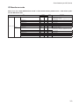
Shared memory and X/Y device
Item
Formula 3 Auto Bottom
Hold
Formula 3 Bottom Hold
Formula 3 Auto Peak to
Peak Hold
Measurement result
Formula 3 Peak to Peak
Hold
Formula 3 Auto Average
Hold
Formula 3 Average Hold
Formula 3 Count
Receiving data 1
Receiving data 2
Reserved
Reserved
Reserved
Reserved
Reserved
Reserved
Element 1 of Formula 1
Result
Element 2 of Formula 1
Element 3 of Formula 1
Element 1 of Formula 2
Element of Formula
Element 2 of Formula 2
Element 3 of Formula 2
Element 1 of Formula 3
Element 2 of Formula 3
Element 3 of Formula 3
Reserved
Reserved
Reserved
Reserved
Reserved
Reserved
Calculation Overflow
Error status
Formula 1
Formula 2
Formula 3
Head A
Head B
Address
Hex.
Dec.
0110h
272
0111h
273
0112h
274
0113h
275
0114h
276
0115h
277
0116h
278
0117h
279
0118h
280
0119h
281
011Ah
282
011Bh
283
011Ch
284
011Dh
285
011Eh
286
011Fh
287
0120h
288
0121h
289
0122h
290
0123h
291
0124h
292
0125h
293
0126h
294
0127h
295
0128h
296
0129h
297
012Ah
298
012Bh
299
012Ch
300
012Dh
301
012Eh
302
012Fh
303
0130h
304
0131h
305
0132h
306
0133h
307
0134h
308
0135h
309
0136h
310
0137h
311
0138h
312
0139h
313
013Ah
314
013Bh
315
013Ch
316
013Dh
317
013Eh
318
013Fh
319
0140h
320
Reserved
Reserved
Reserved
Current Bank number
Version
Q1~Q5 and source status
0141h
0142h
0143h
0144h
0145h
0146h
321
322
323
324
325
326
Response speed (μs)
Storage current pointer
0147h
0148h
0149h
014Ah
327
328
329
330
Reserved
014Bh
Reserved
014Ch
Reserved
014Dh
1st
Depends on "Source of 014Eh
data" address 120
014Fh
~
~
16216 Depends on "Source of 7FFCh
th
data" address 120
7FFDh
7FFEh
7FFFh
331
332
333
334
335
Default
LOW
HI
LOW
HI
LOW
HI
LOW
HI
LOW
HI
LOW
HI
LOW
HI
LOW
HI
LOW
HI
Unit status
Loaded data
Reserved
3-8
32764
32765
32766
32767
080000000h (-2147483648) ~ 7FFFFFFFh (2147483647)
set by “Pointer clear timing”
080000000h (-2147483648) ~ 7FFFFFFFh (2147483647)
set by “Pointer clear timing”
0 ~ 7FFFFFFFh (2147483647)
set by “Pointer clear timing”
0 ~ 7FFFFFFFh (2147483647)
set by “Pointer clear timing”
080000000h (-2147483648) ~ 7FFFFFFFh (2147483647)
set by “Pointer clear timing”
080000000h (-2147483648) ~ 7FFFFFFFh (2147483647)
set by “Pointer clear timing”
080000000h (-2147483648) ~ 7FFFFFFFh (2147483647)
set by “Pointer clear timing”
080000000h (-2147483648) ~ 7FFFFFFFh (2147483647)
080000000h (-2147483648) ~ 7FFFFFFFh (2147483647)
080000000h (-2147483648) ~ 7FFFFFFFh (2147483647)
080000000h (-2147483648) ~ 7FFFFFFFh (2147483647)
080000000h (-2147483648) ~ 7FFFFFFFh (2147483647)
080000000h (-2147483648) ~ 7FFFFFFFh (2147483647)
080000000h (-2147483648) ~ 7FFFFFFFh (2147483647)
080000000h (-2147483648) ~ 7FFFFFFFh (2147483647)
080000000h (-2147483648) ~ 7FFFFFFFh (2147483647)
080000000h (-2147483648) ~ 7FFFFFFFh (2147483647)
080000000h (-2147483648) ~ 7FFFFFFFh (2147483647)
0
B0= Element 1
B4= Element 1
B8= Element 1
B12= Out of range
B13= Out of range
0
0 ~ 59 = Bank 0 ~ 59
Version
B0=Head A B 1 = H e a d B2=
B
Formula 1
B3=
Formula 2
B4=
Formula 3
B11=Q1
B14=Q4
B15=Q5
0
Unit status
Storage overflow
Parameters
LOW
HI
LOW
HI
LOW
HI
LOW
HI
LOW
HI
LOW
HI
LOW
HI
LOW
HI
LOW
HI
0
B12=Q2
B1= Element 2
B5= Element 2
B9= Element 2
B13=Q3
B2= Element 3
B6= Element 3
B10= Element 3
B3= Formula 1
B7= Formula 2
B11= Formula 3
B6=
B5=
Receiving Receiving
data 2
data 1
LOW
0 ~ 262143 (When the pointer reaches end and “Pointer end control” is 0=Stop, it will
stop at 262143. When “Pointer end control” is 1= Continue from start, it restarts from 0.)
HI
0= Pointer is less than 1= Overflow
262143
LOW
HI
Depends on "Source of data" address 120
LOW
HI
Depends on "Source of data" address 120
Shared memory and X/Y device
● Waveform mode
When Y14, Y15 “Head A/B Waveform mode” is ON, shared memory address 334 ~ 1329 will be updated with Waveform data.
Item
Head A
Waveform data
Head B
Threshold level
Address
Hex.
Decimal
014Eh
334
Peak position 1
014Fh
335
0 ~ 255 (0FFh): UQ1-01
0 ~ 4095 (0FFFh): UQ1-02
65535 (0FFFFh): UQ1-02 (non applicable sensor head)
0 ~ 511 (01FFh)
Peak position 2
Waveform data 1
~
Waveform data 480 (UQ1-01 end of data)
Waveform data 508 (UQ1-02 end of data)
Threshold level
0150h
0151h
~
0331h
034Dh
034Eh
336
337
0 ~ 511 (01FFh)
0 ~ 255 (0FFh)
817
845
846
Peak position 1
Peak position 2
Waveform data 1
~
Waveform data 480 (UQ1-01 end of data)
Waveform data 508 (UQ1-02 end of data)
034Fh
0350h
0351h
~
0531h
054Dh
0 ~ 255 (0FFh)
0 ~ 4095 (0FFFh)
0 ~ 255 (0FFh): UQ1-01
0 ~ 4095 (0FFFh): UQ1-02
65535 (0FFFFh): UQ1-02 (non applicable sensor head)
0 ~ 511 (01FFh)
0 ~ 511 (01FFh)
0 ~ 255 (0FFh)
847
848
849
1329
1357
Default
Parameters
0 ~ 255 (0FFh)
0 ~ 4095 (0FFFh)
3-9
Shared memory and X/Y device
3.1.3
X / Y device in detail
X (input) device
X (input) device is input from UQ1 unit to PLC. It can’t be driven by PLC.
Y (output) device
Y (output) device is output from PLC to UQ1 unit. It can’t be driven by UQ1 unit.
● X (input) device in detail
X00
Reserved. Not to be used.
X01~X0A Upper/Lower status
When Q1~Q5 output is larger (smaller) than Upper/Lower threshold, it will be ON accordingly.
X0B~X0F Judge status
When Q1~Q5 output is in the Upper and Lower threshold level.
Tips
About X01~X0F;
When setup is done correctly, one out of these status will be ON.
For example, regarding Q1, one out of X01~X0A and X0B will be ON.
If the source of the control output (shared memory address 32 for Q1 for example) is "NONE", these
device won't be ON.
BUSY status (X10 / X11 / X12 / X13 / X14 / X15)
BUSY will be activated when UQ1 series can't get measurement result from CD5/CD33.
While the BUSY is ON, reading shared memory will be stopped.
Please don't write anything on shared memory while BUSY is active.
X10 BUSY: Over writing common setup
BUSY (X10) will be ON while over writing common setup.
After activating “Y10 Over writing common setup”, common setup parameters in shared memory will be
over written into the ROM of UQ1 unit.
X11 BUSY: Over writing Bank setup
BUSY (X11) will be ON while over writing Bank setup.
After activating “Y11 Over writing Bank setup”, Bank setup parameters in shared memory will be over written into the ROM of UQ1 unit.
3-10
Shared memory and X/Y device
X12 BUSY: Switching Bank setup
BUSY (X12) will be ON while switching Bank setup.
After activating “Y08 Switching Bank setup”, read out setup parameters of the Bank number specified at
shared memory address 102.
X13 BUSY: Getting data stored
BUSY (X13) will be ON while getting data into shared memory.
After activating “Y0F Getting data stored”, get the data from the internal memory of UQ1 unit into shared
memory. Please refer [3.2.6 Storage setup].
X14 ~ X15 BUSY: Switching Head A/B monitoring mode
BUSY (X14, X15) will be ON while switching monitoring mode of the Head A/B at the up edge and down
edge of “Y14/15 Head A/B Waveform mode”.
X16 ~ X17 Head A/B out of range alarm
Alarm (X16, X17) will be ON while CD5/CD33 sensor head is alarming that it can not detect any objects in
the range whatever the monitoring mode is.
When the sensor head detects the object in the range, the alarm will be OFF.
Error status (X18 / X19 / X1A / X1B / X1C / X1D / X1E / X1F)
Error will be ON when the communication or measurement is not done correctly.
Once, the error is ON, it won’t be OFF even the conditions are released.
Please proceed one of following to release this error.
- Power OFF and Power ON
- Activate “Y16 Error release”
X18 ~ X19 Head A/B connection error
Error (X18, X19) will be ON when the RS-422 connection between CD5/CD33 sensor head and UQ1 unit
has problems.
This Error won’t be ON if the sensor head which has connection problem is not assigned as source of output (Q1~Q5).
X1A FIrST data error
Error (X1A) will be ON when the UQ1 unit can’t get data from another UQ1 unit next to it.
This Error won’t be ON if the input data 1 and 2 are not assigned as source of output (Q1~Q5).
X1B ~ X1F Q1~Q5 Error
This Error (X1B~X1F) will be ON when one of following two conditions is fulfilled.
- The sensor head that is assigned to the output (Q1~Q5) is not connected.
- Overflowed while calculation that is assigned to the output (Q1~Q5).
This Error won’t be ON if the source of output (Q1~Q5) is “NONE”.
3-11
Shared memory and X/Y device
● Y (output) device in detail
Y00 ~ Y04 Zero reset
Zero reset input for the output Q1~Q5.
It resets measured result to “0” at the up edge of the zero reset input adjusting offset.
BUSY (X11) will be ON while Zero reset.
Y08 Switching Bank
By activating “Y08”, it switches Bank.
It reads out Bank setup parameters of the Bank number specified at shared memory address 102 and
over write shared memory address 128~157 at up edge of this device.
BUSY (X12: Switching Bank) will be ON while switching Bank.
Y09 RESET
By activating “Y09”, it resets the UQ1 unit.
It clears the value held in “Hold mode”.
While Data clear timing (shared memory address 122) is “1=only when RESET”, it clears the value held in
“Hold mode”.
Y0A ~ Y0E Trigger IN
Trigger input for sensor head A/B and calculation 1/2/3.
Trigger can be input to Y device and terminal block.
Tips
When the trigger is input from terminal block, It works regardless of scan timing of the sequencer.
Y0F Getting Data stored
Start transfer of data stored.
While measurement, the data is stored into internal memory of the unit.
By activating “Y0F”, the data is transferred from internal memory to shared memory.
Please refer [3.2.6 Storage setup].
While transferring the data, X13 BUSY: Getting Data stored will be ON.
Y10 Over writing common setup
Start over writing common setup parameters.
Just changing parameters in the shared memory doesn’t affect actual process of the unit.
By activating this “Y10” device, the parameters are over written on the memory for processing and come
into effect.
The parameters to be over written are in the shared memory address 0~127 except reserved area.
It reads out Bank setup parameters of the Bank number specified at shared memory address 102 and
over write shared memory address 128~157 at up edge of this device.
While over writing the data, X10 BUSY Over writing common setup will be ON.
3-12
Shared memory and X/Y device
Y11 Over writing Bank setup
Start over writing Bank setup parameters including upper and lower threshold.
Just changing parameters in the shared memory doesn’t affect actual process of the unit.
By activating this “Y11” device, the parameters are over written on the memory for processing and come
into effect.
The parameters to be over written are in the shared memory address 128~157 except reserved area.
While over writing the data, X11 BUSY Over writing Bank setup will be ON.
Y12 ~ Y13 LASER OFF
You can make the laser output of each CD5/CD33 sensor head OFF by activating this device.
While laser is OFF, measurement is stopped.
Y14 ~ Y15 Waveform mode
By activating this device, monitoring mode of each sensor head is changed to Waveform monitoring
mode. While it’s Waveform mode, the sensor head doesn’t measure but update the Waveform data on.
Y16 Error release
You can release Error by activating this device.
Besides activating this device, you can release the Error by restart power supply of the UQ1 unit.
3-13
Shared memory and X/Y device
3.1.4
Parameters in shared memory
Major parameters in the shared memory are as follows.
Common setup parameters
Address: 0~126
Parameters for CD5 sensor head and UQ1 unit.
Please change parameters hear firstly to change setup.
Common setup parameters consist of following.
- Setup of sensor head A/B
- High speed mode (ON/OFF)
- Output and Calculation
- Etc.
- Output setup / Trigger input
- Data storing
Initialize
Address: 127
Initialize setup of UQ1 unit.
Bank setup parameters
Address: 128~159
Threshold level and offset for every Bank.
When the Bank is switched, the parameters will be over written.
The parameters include:
- Q1~Q5 Upper/Lower threshold
- Q1~Q5 Offset
Measurement result
Address: 160~319
Result (value) will be shown.
The result include:
- Q1~Q5 result
- Center stand off
- Measurement result
- Calculation factor
Error status
Address: 320~323
Shows every error status.
3-14
Shared memory and X/Y device
Unit status
Address: 324~333
Shows every status of the unit.
Loaded data
Address: 334~32767
Will be updated when getting data from internal memory.
Please refer [3.2.6 Storage setup] about setup of getting data stored.
Waveform data
Address: 334~1329
Will be updated when Waveform monitoring mode.
Tips
Please don't access "Reserved" area of shared memory.
It may cause malfunction of UQ1 unit.
3-15
Parameters in detail
3.2 Parameters in detail
3.2.1
Sensor head setup
Following parameters (shared memory address 0~30) are for setup of CD5/CD33 sensor head.
■ UQ1-01
Address
Hex. Decimal
Measurement target 0000h
0
Diffuse / Specular
0001h
1
Laser power
0002h
2
Sensitivity
0003h
3
Threshold
0004h
4
Sensor
Shift
0005h
5
head A
0006h
6
setup
Span
0007h
7
Over
0008h
8
written by Moving average
0009h
9
Y10=1
number
Item
Sensor
head B
setup
Alarm processing
Sampling period
Reserved
Reserved
Measurement target
Diffuse / Specular
Laser power
Sensitivity
Threshold
Shift
Span
Over
written by Moving average
Y10=1
number
Alarm processing
Sampling period
Reserved
Reserved
Cross talk prevention
Sensor
function
head A/B
Filter choice
setup
Cutoff frequency
000Bh
000Ch
000Dh
000Eh
000Fh
0010h
0011h
0012h
0013h
0014h
0015h
0016h
0017h
10
11
12
13
14
15
16
17
18
19
20
21
22
23
0019h
001Ah
001Bh
001Ch
24
25
26
27
28
001Dh
001Eh
29
30
Default
0
0
5
11
0
0
2710H
(10000)
8
0
0
0
0
5
11
0
0
Parameters
0=Surface
0=Diffuse
0=OFF
0=Min.
0~14
LOW
HI
LOW
HI
0=1 time
8=256 times
0=Clamp
0=100us
1=Flip side 2= Glass thickness
3= Glass gap
1=Specular
1~5 (5: MAX.)
1 ~ 10
11=AUTO
15=AUTO
-50000000 ~ +50000000 (depends on the sensor head)
0 ~ 9C3Fh (0 ~ 39999) Example: 10000 means Span=1.0000
1=2 times
2=4 times
3=8 times
4=16 times
5=32 times
9=512 times A=1024 times B=2048 times C=4096 times
1=Hold
1=200us
2=400us
3=800us
4=1600us
5=3200us
0
0
0=Surface
0=Diffuse
0=OFF
0=Min.
0~14
LOW
HI
LOW
HI
0=1 time
8=256 times
0=Clamp
0=100us
1=2 times
2=4 times
3=8 times
4=16 times
5=32 times
9=512 times A=1024 times B=2048 times C=4096 times
1=Hold
1=200us
2=400us
3=800us
4=1600us
5=3200us
0
0=OFF
1=ON
0
0
0=OFF
0=High
1=High pass
~ 7= Low
2710H
(10000)
8
6=64 times
6=AUTO
1=Flip side 2= Glass thickness
3= Glass gap
1=Specular
1~5 (5: MAX.)
1 ~ 10
11=AUTO
15=AUTO
-50000000 ~ +50000000 (depends on the sensor head)
0 ~ 9C3Fh (0 ~ 39999) Example: 10000 means Span=1.0000
6=64 times
6=AUTO
2=Low pass
■UQ1-02
Item
Sensor
head A
setup
Measurement target
Reserved
Laser
Reserved
Reserved
Shift
Span
Over
written by
Moving average number
Y10=1
Alarm processing
Sampling period
Reserved
Reserved
Measurement target
Reserved
Laser
Reserved
Sensor
Reserved
head A
Shift
setup
Span
Over
written by
Moving average number
Y10=1
Alarm processing
Sampling period
Reserved
Reserved
3-16
Address
Hex.
Decimal
0000h
0
0001h
1
0002h
2
0003h
3
0004h
4
0005h
5
0006h
6
0007h
7
0008h
8
0009h
9
000Ah
10
000Bh
11
000Ch
12
000Dh
13
000Eh
14
000Fh
15
0010h
16
0011h
17
0012h
18
0013h
19
0014h
20
0015h
21
0016h
22
0017h
23
0018h
24
0019h
25
001Ah
26
001Bh
27
Default
Parameters
0
0= Peak
1= Surface
1
0=OFF
1=ON
0
1
0
0
LOW
-50000000 b~ +50000000
(Depends on the sensor head. Please refer [3.2.1 Sensor head setup])
HI
LOW
0 ~ 9C3Fh (0 ~ 39999) Example: 10000 means Span=1.0000
HI
0= 1 time
1=16 times 2=64 times
0=Clamp
1=Hold
0=500us (250mm type: 750us)
1=1000us
2=1500us
3=2000us
0
0= Peak
1= Surface
1
0=OFF
1=ON
0
LOW
-50000000 b~ +50000000
(Depends on the sensor head. Please refer [3.2.1 Sensor head setup])
HI
LOW
0 ~ 9C3Fh (0 ~ 39999) Example: 10000 means Span=1.0000
HI
0= 1 time
1=16 times 2=64 times
0=Clamp
1=Hold
0=500us (250mm type: 750us)
1=1000us
2=1500us
3=2000us
2710h
(10000)
2710h
(10000)
1
0
0
7=128 times
2=Flip side
2=Flip side
3= Glass thickness
3= Glass thickness
7=128 times
Parameters in detail
CD5/CD33 sensor head has setup parameters same as shared memory 0~25. These parameters will be over
written with the parameters in shared memory when UQ1 unit detects CD5/CD33 sensor head connected.
Process at detection of CD5
UQ1
UQ1-01 1 2 3 4 5
IN 1 2
LNK
<<NEAR
CD5
JUDGE
ERR.
HEAD A
HAED B
CD5
HEAD
SDA
A
SDB
Parameters will be
over written
CD33
- Address 0~30
- Baud rate
RDA
RDB
SDA
B
SDB
RDA
RDB
A
SYC OUT
B
SIG OUT
2
1
(SG)
1
TRG IN
2
-
COM
+
12VDC
24VDC
80mA
● Measurement target
Choose measurement target mode.
- Peak: Most reflective point (only UQ1-02)
- Surface: Measurement target is the surface of the object. Please use this mode normally.
- Flip side: 2nd surface of the object. Flip side of glass plate for example.
- Glass thickness: Measures distance between 1st surface and 2nd surface.
Transparent glass thickness for example. Available with only specular type sensor head.
- Glass gap: Measures distance between 2nd surface and 3rd surface.
Gap between layered glasses for example. Available with only specular type sensor head.
[Parameters]
UQ1-01
UQ1-02
0: Surface
1: Flip side
2: Glass thickness
3: Glass gap
0: Peak
1: Surface
2: Flip side
3: Glass thickness
● Diffuse / Specular (UQ1-01)
Specify reflection mode of the laser. Please use diffuse mode for the surface that is not reflective or glossy.
Please use specular mode for reflective surface like glass or clean metal surface.
● Laser power (UQ1-01) / Laser (UQ1-02)
Specify laswer power from 0 to 5 for CD5 connected to UQ1-01. It switches laswer power ON or OFF for
CD33 connected to UQ1-02. When it's 0, it stops measurement.
[Parameters]
UQ1-01
0
1~5
UQ1-02
: Laser OFF
: Laser power (1: low ~ 5: High)
0: Laser OFF
1: Laser ON
3-17
Parameters in detail
● Sensitivity (UQ1-01)
Specify sensitivity of laser sensor in the sensor head. It should be set 11 (Auto) normally. When it’s 11 (auto),
the sensor adjusts the sensitivity automatically depends on the strength of the reflection. It takes 2msec. (Max.)
to adjust so please fix the sensitivity when the reflection changes quickly and drastically.
Example: When the object is reflective metal surface and the object continues disappearing from its view and
appear in a view quickly, measurement could be stable by fixing sensitivity.
[Parameters]
0~10
: 0 (weak) ~ 10 (strong)
11
: AUTO
● Threshold (UQ1-01)
Specify threshold level of CD5 to detect peak point of Waveform.
It should be “0” normally.
Tips
Please adjust the threshold level checking Waveform adequately when the object is transparent.
Please refer "Setup software".
Setting "15: Auto" may make measurement stable but might cause less linearity.
[Parameters]
0~14
: Threshold 0 (low) ~ 14 (high)
15
: AUTO
● Shift / Span
Setup Shift and Span to cancel deviation of position and gradient of the sensor head. Please refer “Setup
software” when you calibrate the sensor. Setup range of Shift is as follows depending to sensor head.
Range of Shift
Sensor type
Minimum
Maximum
CD5-Lx25
-100000 (-1mm)
100000 (1mm)
CD5-x30
-500000 (-5mm)
500000 (5mm)
CD5-x85
-2000000 (-20mm)
2000000 (20mm)
CD5-W350
-10000000 (-100mm)
10000000 (100mm)
CD5-W500
-20000000 (-200mm)
20000000 (200mm)
CD5-W2000
-50000000 (-500mm)
50000000 (500mm)
Please calculate Shift and Span as following.
[Shift calculation]
Example (CD5-x85): When correct +85.400mm to +85.000mm
Stand off: 85mm
Measurement range: ±20mm
(85.000 - 85.400)/(20 * 2)= -0.0100
Please input -00100
3-18
Parameters in detail
[Span calculation]
Example (CD5-x85): When correct the distance 10.100mm to 10.000mm
10.100/10.000=1.0100
Please input 10100
● Moving average number
The bigger number, the more stable measurement is and counteract roughness of the surface.
The smaller number, the higher response speed is and detect quick change of the distance.
● Alarm processing
Specify the process when the sensor head A/B malfunction.
[Parameters]
0: Clamp (output “99999999” when malfunction)
1: Hold
(hold previous measurement value when malfunction. It doesn’t output “X16, X17 out of range
alarm”.)
● Sampling period
Specify sampling period of CD5 sensor head.
The shorter period, the faster response but sensitivity will be worse.
When the sampling period is set “6: AUTO”, sampling period will be adjusted and optimized automatically (only
with UQ1-01)
100μs
Response
[Parameters]
UQ1-01
0: 100us
1: 200us
2: 400us
3: 800us
4: 1600us
5: 3200us
6: AUTO
・・・・・
3200μs
Fast
Slow
Sensitivity Low
High
UQ1-02
0: 500us / 750us (250mm type)
1: 1000us
2: 1500us
3: 2000us
● Cross talk prevention function (UQ1-01)
When multiple CD5 sensor heads target same point, measurement may be unstable because of cross talk.
You can prevent cross talk by setting “Cross talk prevention function” ON. Please note that sampling period
will be 6 times in that case.
Please set this parameter OFF when there is no possibility of cross talk.
3-19
Parameters in detail
● Filter choice (UQ1-01)
You can choose frequency band “High pass filter” or “Low pass filter” for UQ1 series.
- High pass filter: You can get higher frequency band more than the cutoff frequency.
- Low pass filter : You can get low frequency band less than the cutoff frequency.
High pass filter
Low pass filter
[Parameters]
0: OFF
1: High pass filter
2: Low pass filter
Tips
• When set High pass filter or Low pass filter, please set Moving average number (shared memory
address 9, 23) as "0: 1 time".
● Cutoff frequency (UQ1-01)
Specify Cutoff frequency for High or Low pass filter.
Please choose the cutoff frequency from 8 level. Actual cutoff frequency depends on the sampling period
Please refer “6.1.1 Cutoff frequency of the filter” for actual cutoff frequency.
[Parameters]
0 ~ 7: Frequency level (0: High ~ 7: low)
3-20
Parameters in detail
3.2.2
High speed mode
Item
High speed mode
Address
Hex.
Decimal
001Fh
31
Default
0
Parameters
0=OFF
1=ON
(It doesn't do averaging when this parameter is 1=ON. "Auto average" and "Average" in measured result will be "0".)
It speeds up calculation by not doing averaging in High speed mode.
This mode to be used when process time of UQ1 series is longer than sampling period of CD5 sensor.
If you use averaging of measured data, this parameter must be “0=OFF”.
You can confirm current process time at “Process time (shared memory address 327)”.
[Parameters]
0: High speed mode=OFF (all of measured data at shared memory address 176~289 will be updated.)
1: High speed mode=ON (only “Auto average” and “Average” in measured data at shared memory address 176~289 will not be updated.)
3-21
Parameters in detail
3.2.3
Q1~Q5 / Calculation setup
Item
Q1 Source
Q1 Hold
Q2 Source
Q2 Hold
Q3 Source
Q3 Hold
Q4 Source
Q4 Hold
Q5 Source
Q5 Hold
Formula source 1-1
Formula source 1-2
Formula source 1-3
Formula source 1-4
Formula source 1-5
Reserved
Fixed value for Formula source 1-1
Fixed value for Formula source 1-2
Fixed value for Formula source 1-3
Fixed value for Formula source 1-4
Q1~Q5 / Calculation setup
Fixed value for Formula source 1-5
Operator 1-1
Operator 1-2
Operator 1-3
Operator 1-4
Formula source 2-1
Formula source 2-2
Formula source 2-3
Formula source 2-4
Formula source 2-5
Reserved
Fixed value for Formula source 2-1
Fixed value for Formula source 2-2
Fixed value for Formula source 2-3
Fixed value for Formula source 2-4
Fixed value for Formula source 2-5
Operator 2-1
Operator 2-2
Operator 2-3
Operator 2-4
Formula source 3-1
Formula source 3-2
Formula source 3-3
Formula source 3-4
Formula source 3-5
Reserved
Fixed value for Formula source 3-1
Fixed value for Formula source 3-2
Fixed value for Formula source 3-3
Fixed value for Formula source 3-4
Fixed value for Formula source 3-5
Operator 3-1
Operator 3-2
Operator 3-3
Operator 3-4
3-22
Address
Default
Hex. Decimal
0020h
32
0
0=A
0021h
33
0
0= None
0022h
34
1
0=A
0023h
35
0
0= None
0024h
36
7
0=A
0025h
37
0
0= None
0026h
38
7
0=A
0027h
0028h
0029h
002Ah
002Bh
002Ch
002Dh
002Eh
002Fh
0030h
0031h
0032h
0033h
0034h
0035h
0036h
0037h
0038h
0039h
003Ah
003Bh
003Ch
003Dh
003Eh
003Fh
0040h
0041h
0042h
0043h
0044h
0045h
0046h
0047h
0048h
0049h
004Ah
004Bh
004Ch
004Dh
004Eh
004Fh
0050h
0051h
0052h
0053h
0054h
0055h
0056h
0057h
0058h
0059h
005Ah
005Bh
005Ch
005Dh
005Eh
005Fh
0060h
0061h
0062h
0063h
0064h
0065h
39
40
41
42
43
44
45
46
47
48
49
50
51
52
53
54
55
56
57
58
59
60
61
62
63
64
65
66
67
68
69
70
71
72
73
74
75
76
77
78
79
80
81
82
83
84
85
86
87
88
89
90
91
92
93
94
95
96
97
98
99
100
101
Parameters
1=B
1= Sample
1=B
1= Sample
1=B
1= Sample
1=B
2= Formula 1
3= Formula 2
4= Formula 3
5= Receiving data1 6= Receiving data2
2= Peak
3= Bottom
4= Peak to Peak
5= Average
2= Formula 1
3= Formula 2
4= Formula 3
5= Receiving data1 6= Receiving data2
2= Peak
3= Bottom
4= Peak to Peak
5= Average
2= Formula 1
3= Formula 2
4= Formula 3
5= Receiving data1 6= Receiving data2
2= Peak
3= Bottom
4= Peak to Peak
5= Average
2= Formula 1
3= Formula 2
4= Formula 3
5= Receiving data1 6= Receiving data2
2= Peak
3= Bottom
4= Peak to Peak
5= Average
2= Formula 1
3= Formula 2
4= Formula 3
5= Receiving data1 6= Receiving data2
2= Peak
2=B
2=B
2=B
2=B
2=B
4= Peak to Peak
3= Bottom
3= Receiving data 1
3= Receiving data 1
3= Receiving data 1
3= Receiving data 1
3= Receiving data 1
0
7
0
0
0
0
0
0
0= None
0=A
0= None
0= None
0= None
0= None
0= None
0= None
1= Sample
1=B
1= Sample
1=A
1=A
1=A
1=A
1=A
0
LOW
HI
LOW
HI
LOW
HI
LOW
HI
LOW
HI
0= +
0= +
0= +
0= +
0= None
0= None
0= None
0= None
0= None
080000000 h (-2147483648) ~ 7FFFFFFFh (2147483647)
0
0
0
0
0
0
0
0
0
0
0
0
0
0
0
0
0
0
0
0
0
0
0
0
0
0
0
0
0
0
0
0
0
0
0
0
LOW
HI
LOW
HI
LOW
HI
LOW
HI
LOW
HI
0= +
0= +
0= +
0= +
0= None
0= None
0= None
0= None
0= None
LOW
HI
LOW
HI
LOW
HI
LOW
HI
LOW
HI
0= +
0= +
0= +
0= +
5= Average
4= Receiving data 2
4= Receiving data 2
4= Receiving data 2
4= Receiving data 2
4= Receiving data 2
7= None
7= None
7= None
7= None
7= None
5= Fixed value 1-1
5= Fixed value 1-2
5= Fixed value 1-3
5= Fixed value 1-4
5= Fixed value 1-5
080000000 h (-2147483648) ~ 7FFFFFFFh (2147483647)
080000000 h (-2147483648) ~ 7FFFFFFFh (2147483647)
080000000 h (-2147483648) ~ 7FFFFFFFh (2147483647)
080000000 h (-2147483648) ~ 7FFFFFFFh (2147483647)
1= 1= 1= 1= 1=A
1=A
1=A
1=A
1=A
2= *
2= *
2= *
2= *
2=B
2=B
2=B
2=B
2=B
3=÷
3=÷
3=÷
3=÷
3= Receiving data 1
3= Receiving data 1
3= Receiving data 1
3= Receiving data 1
3= Receiving data 1
4= Receiving data 2
4= Receiving data 2
4= Receiving data 2
4= Receiving data 2
4= Receiving data 2
5= Fixed value 2-1
4= Receiving data 2
4= Receiving data 2
4= Receiving data 2
4= Receiving data 2
4= Receiving data 2
5= Fixed value 3-1
5= Fixed value 2-2
5= Fixed value 2-3
5= Fixed value 2-4
5= Fixed value 2-5
080000000 h (-2147483648) ~ 7FFFFFFFh (2147483647)
080000000 h (-2147483648) ~ 7FFFFFFFh (2147483647)
080000000 h (-2147483648) ~ 7FFFFFFFh (2147483647)
080000000 h (-2147483648) ~ 7FFFFFFFh (2147483647)
080000000 h (-2147483648) ~ 7FFFFFFFh (2147483647)
1= 1= 1= 1= 1=A
1=A
1=A
1=A
1=A
2= *
2= *
2= *
2= *
2=B
2=B
2=B
2=B
2=B
3=÷
3=÷
3=÷
3=÷
3= Receiving data 1
3= Receiving data 1
3= Receiving data 1
3= Receiving data 1
3= Receiving data 1
080000000 h (-2147483648) ~ 7FFFFFFFh (2147483647)
080000000 h (-2147483648) ~ 7FFFFFFFh (2147483647)
080000000 h (-2147483648) ~ 7FFFFFFFh (2147483647)
080000000 h (-2147483648) ~ 7FFFFFFFh (2147483647)
080000000 h (-2147483648) ~ 7FFFFFFFh (2147483647)
1= 1= 1= 1= -
2= *
2= *
2= *
2= *
3=÷
3=÷
3=÷
3=÷
5= Fixed value 3-2
5= Fixed value 3-3
5= Fixed value 3-4
5= Fixed value 3-5
Parameters in detail
UQ1 has 5 control outputs, Q1~Q5, in the unit that judge measured result OK or NG.
Each control output has Source and Hold mode to set.
● Q1 ~ Q5 source
Specify the source of each control output.
[Parameters]
0: Head A
1: Head B
2: Formula 1
3: Formula 2
4: Formula 3
5: Receiving data 1
6: Receiving data 2
7: None
● Q1 ~ Q5 Hold
Specify Hold mode for judging Q1~Q5.
[Parameters]
0: Hond None
1: Sample Hold
2: Peak Hold
3: Bottom Hold
4: Peak to Peak Hold
5: Average Hold (doesn’t work when it’s High speed mode)
● Formula 1 ~ 3
Specify formula for the calculation. It can be source of Q1~Q5.
Formula
Source
1
Formula
Source
1
2
Operator
Formula
Source
2
Operator
3
Formula
Source
3
4
Operator
Formula
Source
4
5
Operator
● Formula source (1~5)
Specify source of the formula.
[Parameters]
0: None
1: Measurement result of Head A
2: Measurement result of Head B
3: Receiving data 1 (FIrST transmit data 1 from next unit)
4: Receiving data 2 (FIrST transmit data 2 from next unit)
5: Fixed value
● Operator
Specify operator of the formula.
You can use “+: addition”, “-: subtraction”, “*: multiplication” and “÷: division”.
[Parameters]
0: +
1: 2: *
3: ÷
3-23
Parameters in detail
● Example of Formula setup
Actual formula is as following.
Calculation of thickness
Because the distance between two sensor heads is fixed, the object thickness is calculated by t=(A+B)+L.
Please set "L" by calibration using a gauge.
Head A
Head A center
stand off
A
L
t
B
Head B
Head B center
stand off
For example, when the thickness of the object is 10mm and "A+B" is 9.2mm, set the formula as follows. Set the "Fixed value" as "0.800" (L=t-A-B then 10mm - 9.2mm = 0.8mm).
Formula
Source
Head A
Formula
Source
+
Formula
Source
+
Head B
Operator
0.800
Operator
Formula
Source
+
Formula
Source
-
+
Operator
-
Operator
Calculation of step height
Height of the step from the base is calculated by “H=A-B”.
Head A
Head B
B
A
H
Formula for calculation of step height is as follows.
Formula
Source
Head A
Formula
Source
-
Head B
Operator
3-24
Formula
Source
+
Operator
-
Formula
Source
+
Operator
-
Formula
Source
+
Operator
-
Parameters in detail
Calculation of inclination
Inclination is calculated with distance between sensor heads (Fixed value “L”).
The formula is as follows.
Approximation
A-B
L
-1
θ= tan
θ= (A - B) / L
Head A
Head B
B
A
H
When the distance between two sensor heads is 80mm for example, the formula is as follows.
Formula
Source
Head A
Formula
Source
-
Formula
Source
÷
Head B
Operator
80.00
Operator
Formula
Source
+
Formula
Source
-
+
Operator
-
Operator
Getting measured data from adjoining unit
The measured data from adjoining unit is treated as “Receiving data 1, 2”.
The data is transmitted from adjoining unit at slave side. Setup should be done at the slave unit. Please
refer “2.1.1 FIrST communication”.
UQ1 unit 1
(master side)
For example, when calculating average
of two Head A connected to each UQ1 unit,
UQ1-01 1 2 3 4 5
IN 1 2
OUT 1 2
LNK
setup is as follows.
<<NEAR
FAR>>
UQ1-01 1 2 3 4 5
JUDGE
ERR.
HEAD A
HAED B
IN 1 2
OUT 1 2
LNK
FIrST
CD5
HEAD
SDA
A
RDA
SDB
RDA
9
8
Transmit data
setup is done
at slave side.
B
1
TRG IN
2
COM
C
D
JUDGE
ERR.
HEAD A
HAED B
0
2
3
SDB
RDA
4
5
6
RDB
A
(SG)
-
B
5
1
RDA
SDA
4
7
FAR>>
1
SDB
RDB
6
RDB
SIG OUT
2
SDA
A
2
A
SYC OUT
B
<<NEAR
CD5
HEAD
3
SDA
- UQ1 unit 1 (master side)
0
1
SDB
RDB
B
UQ1 unit 2
(slave side)
A
SYC OUT
B
7
1
9
SIG OUT
2
B
1
TRG IN
2
-
8
A
(SG)
COM
C
D
+
E
+
E
12VDC
24VDC
80mA
F
12VDC
24VDC
80mA
F
Setup the formula as follows.
Formula
Source
Head A
Formula
Source
+
Operator
Receiving
data 1
Formula
Source
÷
Operator
2.000
Formula
Source
+
Operator
-
Formula
Source
+
-
Operator
3-25
Parameters in detail
- UQ1 unit 2 (slave side)
Setup as follows.
FIrST transmit data 1 setup (shared memory address 109): 0 (Head A)
Tips
• Process time will be longer when you use calculation.
You can shorten the process time by making calculation not needed inactive setting "Trigger IN
Calculation 1, 2, 3" (Y0C, Y0D, Y0E) as ON.
• When you use "*" or "÷" for the operator, process time will be longer.
• FIrST communication will be done every UQ1 updating timing.
When FIrST communication is done with multiple UQ1 units, the communication delays for total cycle of updating period.
3-26
Parameters in detail
Getting data from the unit not adjoining
For example, when you use 3 UQ1 units connected as following picture, the data from unit 3 can be transferred to unit 1 through unit 2. Unit 1 can’t get the data from unit 3 directly.
When you calculate step height using two
UQ1
Unit 2
UQ1
Unit 1
Head A connected to unit 1 and unit 3, setup
should be done as following.
UQ1
Unit 3
UQ1-01 1 2 3 4 5
IN 1 2
OUT 1 2
LNK
In this example case, Formula 3 of unit 2 is
<<NEAR
UQ1-01 1 2 3 4 5
UQ1-01 1 2 3 4 5
JUDGE IN 1 2
JUDGE
IN 1 2
JUDGE
ERR.
OUT 1 2
ERR.
OUT 1 2
ERR.
HEAD A
HEAD A
HEAD A
HAED B LNK
HAED B LNK
HAED B
FAR>>
<<NEAR FAR>>
<<NEAR FAR>>
CD5
HEAD
used to assign Receiving data 1 as FIrST
CD5
HEAD
SDA
A
Transmit data 1.
RDA
RDB
Although, you can use Formula 1 or 2 as well.
SDB
RDA
SIG OUT
2
1
B
5
2
COM
+
12VDC
24VDC
80mA
SDB
RDA
A
SYC OUT
B
8
9
SIG OUT
2
1
2
D
-
E
COM
+
F
12VDC
24VDC
80mA
RDA
2
3
SDA
4
B
5
4
SDB
5
RDA
6
RDB
7
8
9
A
SYC OUT
B
7
1
9
SIG OUT
2
8
A
(SG)
B
1
TRG IN
1
SDB
RDB
A
(SG)
C
2
6
RDB
7
0
SDA
A
3
SDA
B
1
TRG IN
RDA
RDB
4
0
1
SDB
2
A
(SG)
-
A
6
RDB
A
SYC OUT
B
CD5
HEAD
SDA
3
SDA
B
0
1
SDB
B
1
TRG IN
C
C
2
D
-
E
+
F
D
COM
E
F
12VDC
24VDC
80mA
Formula 1
Formula 2
Formula 3
- UQ1 unit 1 (master)
Set the Formula as follows.
Formula
Source
Head A
Formula
Source
Formula
Source
Receiving
data 1
-
Operator
+
Formula
Source
-
Operator
+
-
Operator
Formula
Source
+
-
Operator
- UQ1 unit 2 (center unit)
Set the Formula and FIrST Transmit data 1 as follows.
Formula
Source
Receiving
data 1
Formula
Source
+
Operator
-
Formula
Source
+
Operator
-
Formula
Source
+
-
Operator
Formula
Source
+
-
Operator
FIrST Transmit data 1 (shared memory address 109): 4 (Formula 3)
- UQ1 unit 3 (slave side)
Setup as follows.
FIrST Transmit data 1 (shared memory address 109): 0 (Head A)
3-27
Parameters in detail
3.2.4
Setup of other parameters (Etc.)
Etc.
Item
Bank number
Hold mode
Hysteresis
Address
Hex.
Decimal
0066h
102
0067h
103
0068h
104
0069h
105
Default
0
0
0
Parameters
0 ~ 59 = Bank 0 ~ 59
0 = Auto (data clear when RESET) 1 = Normal (data clear when sampling starts)
LOW
0 ~ 7FFFFFFFh (2147483647)
HI
● Bank number
Up to 60 threshold level of Q1~Q5 can be stored in the UQ1 unit.
Following threshold and offset are stored in the Bank.
- Q1~Q5 Upper/Lower threshold (shared memory address 128~147)
- Q1~Q5 Offset (shared memory address 148~157)
Over writing Bank setup
You can over write Bank setup parameters by following procedure.
<1> Set Bank number to over write into “Bank number” (shared memory address 102)
<2> Setup “Bank setup parameters” (shared memory address 128~159).
<3> Set Y11: “Over writing Bank setup” ON.
While over writing Bank setup, X11 BUSY will be ON and accessing to shared memory stops.
Switching Bank
You can switch the Bank loading setup parameters by following procedure.
<1> Set Bank number to switch to into “Bank number” (shared memory address 102)
<2> Set Y08: “Switching Bank” ON.
While switching the Bank, X12 BUSY will be ON and accessing to shared memory stops.
● Hold mode
Specify process of Hold mode.
Please refer [3.3 Hold mode and process] in detail.
0: Auto Hold mode
- Update data while measuring
- Update data when the trigger is ON
- Clear the data when RESET is ON
1: Normal Hold mode
- While sampling, trigger is OFF, it doesn’t reflect to the level.
- At the up edge of the trigger, it reflect to the level and fix.
- While sampling, trigger is OFF, it update the level internally.
3-28
Parameters in detail
● Hysteresis
Specify hysteresis as the distance between the level that Q1~Q5 turns ON and the level that Q1~Q5 goes
OFF after turning ON. The unit is 0.01μm
In the following example, Qx turns ON at A point there the level exceeds upper threshold. Then, Qx goes
OFF at B point there the level goes under “Upper threshold - Hysteresis”.
This feature helps stabilizing the output when the level fluctuates around the threshold level.
Qx doesn’t turn ON unless the level exceeds the threshold so Qx doesn’t turn ON at D point there the level
just exceeds “Upper threshold - Hysteresis”.
C
Qx Upper
threshold
D
Hysteresis
A
B
Qx
3-29
Parameters in detail
3.2.5
Input / Output setup
Address
Default
Hex.
Decimal
On delay
006Ah
106
0
0= None
Off delay
006Bh
107
0
0= None
One shot
006Ch
108
0
0=OFF
FIrST Transmit data 1 setup 006Dh
109
0
0= Head A
FIrST Transmit data 1 Hold 006Eh
110
0
0= None
1 ~ 0FFFFh (65535) ms
1 ~ 0FFFFh (65535) ms
1=ON
1= Head B 2= Formula 1 3= Formula 2
1= Sample 2= Peak
3= Bottom
FIrST Transmit data 2 setup 006Fh
FIrST Transmit data 2 Hold 0070h
111
112
1
0
0= Head A
0= None
1= Head B
1= Sample
Signal Out 1
Signal Out 2
Signal Out logic
0071h
0072h
0073h
113
114
115
0
1
0
Trigger timing of data sam- 0074h
pling
Trigger IN 1
0075h
Trigger IN 2
0076h
116
0
0=Q1
0=Q1
0= All normal
0= OFF
1=Q2
1=Q2
1=1 is
reverse
1= ON
117
118
0
1
0= RESET
0= RESET
1= Head A
1= Head A
Input setup
Output setup
Item
Parameters
* Reflect to Signal Out 1, 2 , X device
* Reflect to Signal Out 1, 2 , X device
* Reflect to Signal Out 1, 2 , X device
4=Formula 3 5= None
4= Peak to 5= Average
Peak
2= Formula 1 3= Formula 2 4=Formula 3 5= None
2= Peak
3= Bottom
4= Peak to 5= Average
Peak
2=Q3
3=Q4
4=Q5
* ON when out side of threshold
2=Q3
3=Q4
4=Q5
* ON when out side of threshold
2=2 is
3= All reverse
reverse
2= Up edge
3= Down edge
* RESET effects at up
edge only
2= Head B
3= Formula 1 4=Formula 2 5=Formula 3
2= Head B
3= Formula 1 4=Formula 2 5=Formula 3
Setup parameters regarding Input and Output.
● ON delay / OFF delay
Specify the delay time of output turning ON and OFF. The unit is msec.
When the width of ON or OFF time of measured result is shorter than ON delay or OFF delay like “A” and “B”
in the following chart. ON delay and OFF delay affect all output.
Measured
result
Qx
ON delay
OFF delay
A
B
● One shot
Specify if output as one shot or not.
When One shot is ON, the output will be ON for the period specified by OFF delay.
One shot affects all output.
Measured
result
Qx
OFF delay
3-30
Parameters in detail
● FIrST Transmit data 1/2 setup, FIrST Transmit data 1/2 hold
Specify the source to send through FIrST to another UQ1 unit at master side.
The data sent from slave side will be assigned as “Receiving data 1/2” in the unit.
Please refer [2.1.1 FIrST communication]
At “FIrST Transmit data 1/2 hold”, specify the hold mode of the data to transmit.
Please refer [3.3 Hold mode and process]
● Signal Out 1/2
Specify the source to output from “Signal Out 1/2” at terminal block.
The indicator LED “OUT 1/2” will be ON when the output is ON.
[Parameters]
0: Q1
1: Q2
2: Q3
3: Q4
4: Q5
● Signal out logic
Specify the logic of the “Signal Out 1/2”.
[Parameters]
0: Normal (ON when the measurement result is out of threshold)
1: The logic of Signal out 1 is reverse (ON when the measurement result is in the threshold)
2: The logic of Signal out 2 is reverse (ON when the measurement result is in the threshold)
3: The logic of Signal out 1 and 2 is reverse (ON when the measurement result is in the threshold)
● Trigger timing of data sampling
Specify the timing of “Trigger IN” to sample the data.
When “RESET” is assigned for Trigger IN 1 or 2, the timing is up edge.
[Parameters]
0: OFF (when Trigger IN is OFF, it samples the data)
1: ON (when Trigger IN is ON, it samples the data)
2: Up edge (at the up edge of Trigger IN, it samples the data)
3: Down edge (at the down edge of Trigger IN, it samples the data)
● Trigger IN 1/2
Specify the source of “Trigger IN 1/2”.
The indicator LED “IN 1/2” will be ON when the input is ON.
[Parameters]
0: RESET (Y09)
1: Head A (Y0A)
2: Head B (Y0B)
3: Formula 1 (Y0C)
4: Formula 2 (Y0D)
5: Formula 3 (Y0E)
3-31
Parameters in detail
3.2.6
Storage setup
Hold mode
Address
Default
Hex. Decimal
0077h
119
0=No skip
0078h
120
0
0=Q1
8= Formula 2
0079h
121
0
0= None
Pointer clear timing
Pointer end control
007Ah
007Bh
122
123
1
1
Storage transfer start
pointer
007Ch
007Dh
124
125
0
Item
Data store skip number
Source of data
Parameters
1 ~ 0FFFFh (65535)
1=Q2
2=Q3
3=Q4
4=Q5
9= Formula 3 * Q1~Q5 will be added its offset.
1= Sample
2= Peak
3=Bottom 4= Peak to
Peak
5= Head A
6= Head B
7= Formula 1
5=Average
* Effective when the source
of data is Head A ~ Formula 3
(5~9)
0=When trigger is ON
1=When RESET is ON
0=Stop
1=Continue
from start
LOW
Start pointer number (0 ~ 245928) of the internal storage memory for transferring to shared memory.
262144 (14Eh~7FFDh) totally (every 16216). This is effective immediately after updating.
HI
Following shows about storage function.
Measured data will be stored regarding to related parameters set. You can transfer the data from storage into
shared memory after the measurement.
● UQ1 data access for storage
UQ1 has internal memory for storage besides
the shared memory.
Measurement data will be stored into the
internal memory firstly.
UQ1-01 1 2 3 4 5
IN 1 2
OUT 1 2
LNK
FAR>>
JUDGE
ERR.
HEAD A
HAED B
Internal memory
Shared memory
(can be referred)
CD5
HEAD
SDA
A
To refer the measurement data, please
proceed following procedure.
<<NEAR
RDA
RDB
2
3
SDA
B
0
1
SDB
SDB
RDA
4
5
6
RDB
A
SYC OUT
B
7
1
9
SIG OUT
2
A
(SG)
B
1
TRG IN
2
-
Stored data
(address:
334~32765)
8
COM
C
D
+
E
12VDC
24VDC
80mA
F
Procedure of getting data transfered to shared memory
1) Storage setup
Setup parameters related to storage of measurement data.
Please refer [1.2.2 UQ1 series data flow] about how to over write shared memory.
2) Getting measurement data from CD5 sensor head into internal memory for storage
UQ1 unit gets the measurement
data from CD5 and store into internal
memory for storage regarding
the setup.
UQ1-01 1 2 3 4 5
IN 1 2
OUT 1 2
LNK
<<NEAR FAR>>
CD5
HEAD
SDA
A
RDA
RDB
SDB
RDA
4
5
6
RDB
A
SYC OUT
B
7
1
9
SIG OUT
2
B
1
TRG IN
2
-
8
A
(SG)
3-32
2
3
SDA
B
0
1
SDB
COM
C
D
+
E
12VDC
24VDC
80mA
F
JUDGE
ERR.
HEAD A
HAED B
Parameters in detail
Tips
Maximum number of data can be stored into the internal memory is 262144 (word).
When the pointer of the memory exceeds end of the memory, it proceeds according to "Pointer end
control" (shared memory address: 123) setup.
3) Get the data transferred
The measurement data can be referred after transferring the data from the storage memory into
shared memory. The start pointer of the storage is specified by “Storage transfer start pointer” (shared
memory address: 124~125).
You can check current pointer of the storage at “Storage current pointer” (shared memory address:
328).
* Over writing by Y10 “Over writing common setup” is not needed.
UQ1-01 1 2 3 4 5
Q00XXCPU
POWER
MODE
RUN
ERR.
USER
BAT.
IN 1 2
OUT 1 2
LNK
<<NEAR
FAR>>
JUDGE
ERR.
HEAD A
HAED B
CD5
HEAD
SDA
A
PULL
RDA
RDB
MITSUBISH I
2
3
SDA
B
0
1
SDB
PULL
SDB
RDA
4
5
6
RDB
A
SYC OUT
B
7
1
9
SIG OUT
2
B
1
TRG IN
2
-
8
A
(SG)
COM
C
D
+
E
12VDC
24VDC
80mA
F
Specify the start pointer
The measurement data will be transferred by setting Y0F “Getting data stored”.
While transferring data, X13 “BUSY Getting data sored” will be ON and stop measurement.
After transferring data to shared memory, the data can be referred by sequencer.
You can transfer the data more than 16216 word changing the pointer.
UQ1-01 1 2 3 4 5
Q00XXCPU
POWER
MODE
RUN
ERR.
USER
BAT.
IN 1 2
OUT 1 2
LNK
<<NEAR
FAR>>
JUDGE
ERR.
HEAD A
HAED B
CD5
HEAD
SDA
A
PULL
PULL
RDA
RDB
MITSUBISH I
2
3
SDA
B
0
1
SDB
SDB
RDA
4
5
6
RDB
A
SYC OUT
B
7
1
9
SIG OUT
2
A
(SG)
B
1
TRG IN
2
-
8
COM
C
D
+
E
12VDC
24VDC
80mA
F
The data will be transferred by
setting Y0F "Getting data stored"
3-33
Parameters in detail
● Data store skip number
Specify the number to skip when storing data from CD5 sensor head to the storage memory.
After storing one data, it skips the number of data specified before next storing.
When “0” is set, all the data will be stored.
Example: Store one data while sampling 10 times.
Data store skip number: 9
When UQ1 update period is 100μs: 0.1ms * 10 = 1ms (store one data every 1ms)
When UQ1 update period is 3200μs: 3.2ms * 10 = 32ms (store one data every 32ms)
● Source of data
Specify the source of data to store.
When Q1~Q5 is chosen, its offset will be added before storing.
[Parameters]
0: Q1
1: Q2
2: Q3
3: Q4
4: Q5
5: Head A
6: Head B
7: Formula 1
8: Formula 2
9: Formula 3
● Hold mode
Specify the hold mode of the source of data.
Effective when the source of data is Head A/B, Formula 1/2/3 (shared memory address 120 is 5~9).
[Parameters]
0: None
1: Sample
2: Peak
3: Bottom
4: Peak to Peak
5: Average
● Storage of 2 measurement result (UQ1-02)
You can store 2 measurement result with UQ1-02 at a time.
Maximum number of the data is 131071 (1FFFFh) for each measurement result.
Setup as follows.
Item
Address
Parameters
Hex. Decimal 1000h
100h
10h
Source of data
0078h 120
0
(2nd parameter)
Hold mode
0079h 121
0
(2nd parameter)
"Storage current pointer" (shared memory 328, 329) shows 1st pointer.
1h
1
0
2nd pointer is "Storage current pointer" + 131072 (20000h).
Example: "Source of data": 1st Q2, 2nd Q3 → 1 + 10h(16) +( 2 * 100h(256)) = 211h(529)
Example: "Hold mode": 1st Peak, 2nd Bottom → 2 +( 3 * 100h(256)) = 302h(770)
3-34
(1st parameter)
(1st parameter)
Parameters in detail
Tips
UQ1-01 later version than 2 support storing 2 measurement result.
You can confirm the version on the label.
There is version number above the "CE" mark.
With no version shown as following picture it's version 1.
If you proceed storing 2 measurement result with UQ1 of version 1, it will store only one measurement result of Q1 with Hold mode: "None".
● Pointer clear timing
Specify the timing to clear the pointer.
- When the Trigger is ON
When the trigger is ON, when storing starts, the pointer is cleared.
- When the RESET is ON
When Y09 “RESET” is ON, the pointer is cleared.
When the trigger is ON, it continues storing new data increasing the pointer.
[Parameters]
0: Trigger is ON
1: RESET is ON
● Pointer end control
Specify the process of the pointer when the pointer reaches end of the storage memory.
[Parameters]
0: Stop (stops storing measurement data)
1: Continue from start (clear the pointer and continue storing the data)
● Storage transfer start pointer
Specify start pointer of storage memory (0~245928) for transferring to shared memory.
It affects immediately right after setting this parameter (no need setting Y10 “Over writing common setup”).
Data is stored being numbered from 0.
When the pointer is specified, 16216 data will be transferred to “Loaded data” (shared memory address
14Eh~7FFDh) from the address pointed by the pointer.
0~245928: Storage transfer start pointer
Tips
When set start pointer as bigger than 245928, data over 262144 will be stored from 0.
3-35
Parameters in detail
3.2.7
Initializing
Address
Item
Hex.
Initialize
Default
Parameters
Decimal
007Fh
127
0101h
* Initialize by rebooting after setting this parameter “0”and Y10 as “1”.
Initialize all setup parameters to default.
Initializing procedure is as follows.
<1> Set Initialize (shared memory address 127) as “0”
<2> Activate Y10 Over writing common setup
<3> After confirming X10 BUSY: Over writing common setup is OFF, shut down the power supply
and re-power.
3.2.8
Bank setup
Address
Item
Default
Hex.
Q1 Upper threshold
Q1 Lower threshold
Q2 Upper threshold
Q2 Lower threshold
Q3 Upper threshold
Q3 Lower threshold
Threshold / Offset
Q4 Upper threshold
Q4 Lower threshold
Q5 Upper threshold
Q5 Lower threshold
Q1 Offset
Q2 Offset
Q3 Offset
Q4 Offset
Q5 Offset
Reserved
Reserved
0080h
0081h
0082h
0083h
0084h
0085h
0086h
0087h
0088h
0089h
008Ah
008Bh
008Ch
008Dh
008Eh
008Fh
0090h
0091h
0092h
0093h
0094h
0095h
0096h
0097h
0098h
0099h
009Ah
009Bh
009Ch
009Dh
009Eh
009Fh
Parameters
Decimal
128
129
130
131
132
133
134
135
136
137
138
139
140
141
142
143
144
145
146
147
148
149
150
151
152
153
154
155
156
157
158
159
47868C0h
(75000000)
0FB879740h
(-75000000)
47868C0h
(75000000)
0FB879740h
(-75000000)
47868C0h
(75000000)
0FB879740h
(-75000000)
47868C0h
(75000000)
0FB879740h
(-75000000)
47868C0h
(75000000)
0FB879740h
(-75000000)
0
0
0
0
0
LOW
HI
LOW
HI
LOW
HI
LOW
HI
LOW
HI
LOW
HI
LOW
HI
LOW
HI
LOW
HI
LOW
HI
LOW
HI
LOW
HI
LOW
HI
LOW
HI
LOW
HI
080000000h (-2147483648) ~ 7FFFFFFFh (2147483647)
(Offset is reflected)
080000000h (-2147483648) ~ 7FFFFFFFh (2147483647)
(Offset is reflected)
080000000h (-2147483648) ~ 7FFFFFFFh (2147483647)
(Offset is reflected)
080000000h (-2147483648) ~ 7FFFFFFFh (2147483647)
(Offset is reflected)
080000000h (-2147483648) ~ 7FFFFFFFh (2147483647)
(Offset is reflected)
080000000h (-2147483648) ~ 7FFFFFFFh (2147483647)
(Offset is reflected)
080000000h (-2147483648) ~ 7FFFFFFFh (2147483647)
(Offset is reflected)
080000000h (-2147483648) ~ 7FFFFFFFh (2147483647)
(Offset is reflected)
080000000h (-2147483648) ~ 7FFFFFFFh (2147483647)
(Offset is reflected)
080000000h (-2147483648) ~ 7FFFFFFFh (2147483647)
(Offset is reflected)
080000000h (-2147483648) ~ 7FFFFFFFh (2147483647)
080000000h (-2147483648) ~ 7FFFFFFFh (2147483647)
080000000h (-2147483648) ~ 7FFFFFFFh (2147483647)
080000000h (-2147483648) ~ 7FFFFFFFh (2147483647)
080000000h (-2147483648) ~ 7FFFFFFFh (2147483647)
Setup parameters for each Bank.
● Q1 ~ Q5 Upper threshold, Q1 ~ Q5 Lower threshold
Specify threshold of Q1 ~ Q5.
Judge (OK or NG) will be done for each value including its offset.
● Offset Q1 ~ Q5
Specify offset value for each Q1 ~ Q5.
When Y00 ~ Y04 Zero reset for Q1 ~ Q5 is ON, offset of corresponding Qx will be adjusted so that the Qx to
be “0”.
3-36
Parameters in detail
3.2.9
Q1 ~ Q5 result
Address
Item
Hex.
Q1 ~ Q5 result
Q1
00A0h
00A1h
00A2h
00A3h
00A4h
00A5h
00A6h
00A7h
00A8h
00A9h
Q2
Q3
Q4
Q5
Default
Parameters
Decimal
160
161
162
163
164
165
166
167
168
169
LOW
HI
LOW
HI
LOW
HI
LOW
HI
LOW
HI
080000000h (-2147483648) ~ 7FFFFFFFh (2147483647)
(Offset is reflected)
080000000h (-2147483648) ~ 7FFFFFFFh (2147483647)
(Offset is reflected)
080000000h (-2147483648) ~ 7FFFFFFFh (2147483647)
(Offset is reflected)
080000000h (-2147483648) ~ 7FFFFFFFh (2147483647)
(Offset is reflected)
080000000h (-2147483648) ~ 7FFFFFFFh (2147483647)
(Offset is reflected)
● Q1 ~ Q5 result
Q1 ~ Q5 will be used for Signal out 1/2.
Q1 ~ Q5 is its source (Head or Formula or Receiving data) + its offset.
Center stand off
Item
Address
Hex.
Decimal
Head A Center stand off
00AAh
00ABh
170
171
Head B Center stand off
00ACh
00ADh
172
173
Reserved
Reserved
00AEh
00AFh
174
175
Default
Fixed
value by
type
Fixed
value by
type
Parameters
LOW
HI
2500000(25mm) ~ 200000000 (2000mm)
LOW
HI
2500000(25mm) ~ 200000000 (2000mm)
● Head A/B Center stand off
Center stand off will be set automatically recognizing connected CD5 sensor type.
This value will be utilized for reference as absolute center stand off.
Example: 85.000mm for CD5-85
3-37
Parameters in detail
Item
Head A
Head A Sample Hold
Head A Auto Peak hold
Head A Peak Hold
Head A Auto Bottom Hold
Head A Bottom Hold
Head A Auto Peak to Peak
Hold
Head A Peak to Peak Hold
Head A Auto Average Hold
Head A Average Hold
Head A Count
Head B
Head B Sample Hold
Head B Auto Peak hold
Head B Peak Hold
Head B Auto Bottom Hold
Head B Bottom Hold
Head B Auto Peak to Peak
Hold
Measurement result
Head B Peak to Peak Hold
Head B Auto Average Hold
Head B Average Hold
Head B Count
Formula 1
Formula 1 Sample Hold
Formula 1 Auto Peak Hold
Formula 1 Peak Hold
Formula 1 Auto Bottom Hold
Formula 1 Bottom Hold
Formula 1 Auto Peak to Peak
Hold
Formula 1 Peak to Peak Hold
Formula 1 Auto Average Hold
Formula 1 Average Hold
Formula 1 Count
Formula 2
Formula 2 Sample Hold
Formula 2 Auto Peak Hold
Formula 2 Peak Hold
Formula 2 Auto Bottom Hold
Formula 2 Bottom Hold
Formula 2 Auto Peak to Peak
Hold
3-38
Address
Hex.
00B0h
00B1h
00B2h
00B3h
00B4h
00B5h
00B6h
00B7h
00B8h
00B9h
00BAh
00BBh
00BCh
00BDh
00BEh
00BFh
00C0h
00C1h
00C2h
00C3h
00C4h
00C5h
00C6h
00C7h
00C8h
00C9h
00CAh
00CBh
00CCh
00CDh
00CEh
00CFh
00D0h
00D1h
00D2h
00D3h
00D4h
00D5h
00D6h
00D7h
00D8h
00D9h
00DAh
00DBh
00DCh
00DDh
00DEh
00DFh
00E0h
00E1h
00E2h
00E3h
00E4h
00E5h
00E6h
00E7h
00E8h
00E9h
00EAh
00EBh
00ECh
00EDh
00EEh
00EFh
00F0h
00F1h
00F2h
00F3h
00F4h
00F5h
00F6h
00F7h
00F8h
00F9h
00FAh
00FBh
00FCh
00FDh
00FEh
00FFh
Decimal
176
177
178
179
180
181
182
183
184
185
186
187
188
189
190
191
192
193
194
195
196
197
198
199
200
201
202
203
204
205
206
207
208
209
210
211
212
213
214
215
216
217
218
219
220
221
222
223
224
225
226
227
228
229
230
231
232
233
234
235
236
237
238
239
240
241
242
243
244
245
246
247
248
249
250
251
252
253
254
255
Default
Parameters
LOW
HI
LOW
HI
LOW
HI
LOW
HI
LOW
HI
LOW
HI
LOW
HI
LOW
HI
LOW
HI
LOW
HI
LOW
HI
LOW
HI
LOW
HI
LOW
HI
LOW
HI
LOW
HI
LOW
HI
LOW
HI
LOW
HI
LOW
HI
LOW
HI
LOW
HI
LOW
HI
LOW
HI
LOW
HI
LOW
HI
LOW
HI
LOW
HI
LOW
HI
LOW
HI
LOW
HI
LOW
HI
LOW
HI
LOW
HI
LOW
HI
LOW
HI
LOW
HI
LOW
HI
LOW
HI
LOW
HI
080000000h (-2147483648) ~ 7FFFFFFFh (2147483647)
080000000h (-2147483648) ~ 7FFFFFFFh (2147483647)
set by “Pointer clear timing”
080000000h (-2147483648) ~ 7FFFFFFFh (2147483647)
set by “Pointer clear timing”
080000000h (-2147483648) ~ 7FFFFFFFh (2147483647)
set by “Pointer clear timing”
080000000h (-2147483648) ~ 7FFFFFFFh (2147483647)
set by “Pointer clear timing”
080000000h (-2147483648) ~ 7FFFFFFFh (2147483647)
set by “Pointer clear timing”
0 ~ 7FFFFFFFh (2147483647)
set by “Pointer clear timing”
0 ~ 7FFFFFFFh (2147483647)
set by “Pointer clear timing”
080000000h (-2147483648) ~ 7FFFFFFFh (2147483647)
set by “Pointer clear timing”
080000000h (-2147483648) ~ 7FFFFFFFh (2147483647)
set by “Pointer clear timing”
080000000h (-2147483648) ~ 7FFFFFFFh (2147483647)
set by “Pointer clear timing”
080000000h (-2147483648) ~ 7FFFFFFFh (2147483647)
080000000h (-2147483648) ~ 7FFFFFFFh (2147483647)
set by “Pointer clear timing”
080000000h (-2147483648) ~ 7FFFFFFFh (2147483647)
set by “Pointer clear timing”
080000000h (-2147483648) ~ 7FFFFFFFh (2147483647)
set by “Pointer clear timing”
080000000h (-2147483648) ~ 7FFFFFFFh (2147483647)
set by “Pointer clear timing”
080000000h (-2147483648) ~ 7FFFFFFFh (2147483647)
set by “Pointer clear timing”
0 ~ 7FFFFFFFh (2147483647)
set by “Pointer clear timing”
0 ~ 7FFFFFFFh (2147483647)
set by “Pointer clear timing”
080000000h (-2147483648) ~ 7FFFFFFFh (2147483647)
set by “Pointer clear timing”
080000000h (-2147483648) ~ 7FFFFFFFh (2147483647)
set by “Pointer clear timing”
080000000h (-2147483648) ~ 7FFFFFFFh (2147483647)
set by “Pointer clear timing”
080000000h (-2147483648) ~ 7FFFFFFFh (2147483647)
080000000h (-2147483648) ~ 7FFFFFFFh (2147483647)
set by “Pointer clear timing”
080000000h (-2147483648) ~ 7FFFFFFFh (2147483647)
set by “Pointer clear timing”
080000000h (-2147483648) ~ 7FFFFFFFh (2147483647)
set by “Pointer clear timing”
080000000h (-2147483648) ~ 7FFFFFFFh (2147483647)
set by “Pointer clear timing”
080000000h (-2147483648) ~ 7FFFFFFFh (2147483647)
set by “Pointer clear timing”
0 ~ 7FFFFFFFh (2147483647)
set by “Pointer clear timing”
0 ~ 7FFFFFFFh (2147483647)
set by “Pointer clear timing”
080000000h (-2147483648) ~ 7FFFFFFFh (2147483647)
set by “Pointer clear timing”
080000000h (-2147483648) ~ 7FFFFFFFh (2147483647)
set by “Pointer clear timing”
080000000h (-2147483648) ~ 7FFFFFFFh (2147483647)
set by “Pointer clear timing”
080000000h (-2147483648) ~ 7FFFFFFFh (2147483647)
080000000h (-2147483648) ~ 7FFFFFFFh (2147483647)
set by “Pointer clear timing”
080000000h (-2147483648) ~ 7FFFFFFFh (2147483647)
set by “Pointer clear timing”
080000000h (-2147483648) ~ 7FFFFFFFh (2147483647)
set by “Pointer clear timing”
080000000h (-2147483648) ~ 7FFFFFFFh (2147483647)
set by “Pointer clear timing”
080000000h (-2147483648) ~ 7FFFFFFFh (2147483647)
set by “Pointer clear timing”
0 ~ 7FFFFFFFh (2147483647)
set by “Pointer clear timing”
Parameters in detail
Item
Formula 2 Peak to Peak Hold
Formula 2 Auto Average Hold
Formula 2 Average Hold
Formula 2 Count
Formula 3
Formula 3 Sample Hold
Formula 3 Auto Peak Hold
Formula 3 Peak Hold
Measurement result
Formula 3 Auto Bottom Hold
Formula 3 Bottom Hold
Formula 3 Auto Peak to Peak
Hold
Formula 3 Peak to Peak Hold
Formula 3 Auto Average Hold
Formula 3 Average Hold
Formula 3 Count
Receiving data 1
Receiving data 2
Reserved
Reserved
Reserved
Reserved
Reserved
Reserved
Address
Hex.
Decimal
0100h
0101h
0102h
0103h
0104h
0105h
0106h
0107h
0108h
0109h
010Ah
010Bh
010Ch
010Dh
010Eh
010Fh
0110h
0111h
0112h
0113h
0114h
0115h
0116h
0117h
0118h
0119h
011Ah
011Bh
011Ch
011Dh
011Eh
011Fh
0120h
0121h
0122h
0123h
0124h
0125h
0126h
0127h
256
257
258
259
260
261
262
263
264
265
266
267
268
269
270
271
272
273
274
275
276
277
278
279
280
281
282
283
284
285
286
287
288
289
290
291
292
293
294
295
Default
Parameters
LOW
HI
LOW
HI
LOW
HI
LOW
HI
LOW
HI
LOW
HI
LOW
HI
LOW
HI
LOW
HI
LOW
HI
LOW
HI
LOW
HI
LOW
HI
LOW
HI
LOW
HI
LOW
HI
LOW
HI
0 ~ 7FFFFFFFh (2147483647)
set by “Pointer clear timing”
080000000h (-2147483648) ~ 7FFFFFFFh (2147483647)
set by “Pointer clear timing”
080000000h (-2147483648) ~ 7FFFFFFFh (2147483647)
set by “Pointer clear timing”
080000000h (-2147483648) ~ 7FFFFFFFh (2147483647)
set by “Pointer clear timing”
080000000h (-2147483648) ~ 7FFFFFFFh (2147483647)
080000000h (-2147483648) ~ 7FFFFFFFh (2147483647)
set by “Pointer clear timing”
080000000h (-2147483648) ~ 7FFFFFFFh (2147483647)
set by “Pointer clear timing”
080000000h (-2147483648) ~ 7FFFFFFFh (2147483647)
set by “Pointer clear timing”
080000000h (-2147483648) ~ 7FFFFFFFh (2147483647)
set by “Pointer clear timing”
080000000h (-2147483648) ~ 7FFFFFFFh (2147483647)
set by “Pointer clear timing”
0 ~ 7FFFFFFFh (2147483647)
set by “Pointer clear timing”
0 ~ 7FFFFFFFh (2147483647)
set by “Pointer clear timing”
080000000h (-2147483648) ~ 7FFFFFFFh (2147483647)
set by “Pointer clear timing”
080000000h (-2147483648) ~ 7FFFFFFFh (2147483647)
set by “Pointer clear timing”
080000000h (-2147483648) ~ 7FFFFFFFh (2147483647)
set by “Pointer clear timing”
080000000h (-2147483648) ~ 7FFFFFFFh (2147483647)
080000000h (-2147483648) ~ 7FFFFFFFh (2147483647)
● Measurement result
Measurement result will be set.
Measurement result is updated every updating period of UQ1 regardless of setup of Q1 ~ Q5.
Its process while the trigger is OFF depends on setup of “Hold mode” (shared memory address 103).
When Y09 RESET is ON, the value will be reset.
-0 (Auto mode): When the trigger is OFF, the value will be reset
-1 (Hold mode): The value won’t be reset when the trigger is OFF
Tips
Offset value won't be added on the measurement result.
The data from the slave UQ1 unit through FIrST will be set to “Receiving data”. Please refer [2.1.1 FIrST
communication].
Tips
• The receiving data to be set at slave side unit.
• When the communication data is not available or the data is broken, "0" will be set.
• When "High speed mode" (shared memory address 31) is ON, "Average" and "Average Hold" will
be set "0".
3-39
Parameters in detail
Address
Item
Hex.
Element 1 of Formula 1
Element 2 of Formula 1
Element 3 of Formula 1
Element 1 of Formula 2
Element of Formula
Element 2 of Formula 2
Element 3 of Formula 2
Element 1 of Formula 3
Element 2 of Formula 3
Element 3 of Formula 3
Reserved
Reserved
Reserved
Reserved
Reserved
Reserved
Decimal
0128h
0129h
012Ah
012Bh
012Ch
012Dh
012Eh
012Fh
0130h
0131h
0132h
0133h
0134h
0135h
0136h
0137h
0138h
0139h
013Ah
013Bh
013Ch
013Dh
013Eh
013Fh
Default
296
297
298
299
300
301
302
303
304
305
306
307
308
309
310
311
312
313
314
315
316
317
318
319
Parameters
LOW
HI
LOW
HI
LOW
HI
LOW
HI
LOW
HI
LOW
HI
LOW
HI
LOW
HI
LOW
HI
080000000h (-2147483648) ~ 7FFFFFFFh (2147483647)
080000000h (-2147483648) ~ 7FFFFFFFh (2147483647)
080000000h (-2147483648) ~ 7FFFFFFFh (2147483647)
080000000h (-2147483648) ~ 7FFFFFFFh (2147483647)
080000000h (-2147483648) ~ 7FFFFFFFh (2147483647)
080000000h (-2147483648) ~ 7FFFFFFFh (2147483647)
080000000h (-2147483648) ~ 7FFFFFFFh (2147483647)
080000000h (-2147483648) ~ 7FFFFFFFh (2147483647)
080000000h (-2147483648) ~ 7FFFFFFFh (2147483647)
● Calculation element
Result of each formula element will be set.
Element 1 ~ 3 are calculation result of formula element as follows.
Formula
Source
1
Formula
Source
Formula
Source
1
Operator
2
2
Operator
Element 1
3
Operator
Element 2
Element 3
3-40
3
Formula
Source
4
Formula
Source
4
Operator
5
Parameters in detail
3.2.10 Error status
Address
Item
Calculation Overflow Formula
1
Formula
2
Formula
3
Head A
Head B
Reserve
Reserve
Reserve
Hex.
0140h
Decimal
Default
320
0
Parameters
B0= Element 1
B1= Element 2
B2= Element 3
B3= Formula 1
B4= Element 1
B5= Element 2
B6= Element 3
B7= Formula 2
B8= Element 1
B9= Element 2
B10= Element 3
B11= Formula 3
B12= Out of range Alarm
B13= Out of range Alarm
0141h
0142h
0143h
321
322
323
● Calculation Overflow
When the calculation result overflows, the corresponding bit will be “1”.
These bits won’t be cleared even the overflow is released.
Please proceed one of following procedures to clear the bits.
- Reboot the power supply
- Set Y09 RESET ON
- Set Y16 Error release ON
B0: Element 1 of Formula 1
B1: Element 2 of Formula 1
B2: Element 3 of Formula 1
B3: Formula 1
B4: Element 1 of Formula 2
B5: Element 2 of Formula 2
B6: Element 3 of Formula 2
B7: Formula 2
B8: Element 1 of Formula 3
B9: Element 2 of Formula 3
B10: Element 3 of Formula 3
B11: Formula 3
B12: Head A is out of range
B13: Head B is out of range
3-41
Parameters in detail
3.2.11 Unit status
Address
Item
Hex.
Decimal
Current Bank number
Version
Q1~Q5 and source status
0144h
0145h
0146h
324
325
326
Response speed (μs)
Storage current pointer
Storage overflow
0147h
0148h
0149h
014Ah
327
328
329
330
Reserved
Reserved
Reserved
014Bh
014Ch
014Dh
331
332
333
Default
0
0
Parameters
0 ~ 59 = Bank 0 ~ 59
Version
B0= Head A B1= Head B
B11=Q1
0
0
B12=Q2
B2=Formula
1
B13=Q3
B3=Formula
2
B14=Q4
B4=Formula
3
B15=Q5
B5= Receiving data 1
B6= Receiving data 2
LOW
0 ~ 262143 (When the pointer reaches end and "Pointer end control" is 0=Stop, it will stop at
262143. When "Pointer end control" is 1= Continue from start, it restarts from 0.)
HI
0= Pointer is less than
1= Overflow
262143
Shows if these resources are used or not.
● Current Bank number
Shows the number of the Bank currently set.
● Version
Shows unit version.
● Q1 ~ Q5 and source status
Shows which Qx and its source are used on each bit.
B0: Head A
B1: Head B
B2: Formula 1
B3: Formula 2
B4: Formula 3
B5: Receiving data 1
B6: Receiving data 2
When these are assigned at Q1 ~ Q5, the bit will be ON.
B11: Q1
B12: Q2
B13: Q3
B14: Q4
B15: Q5
● Response speed
Shows response speed of UQ1 unit in μs.
Updating data in the UQ1 unit will be done every 100μs that rounded out the hundred’s place of actual process time. For example, when the actual process time is 140 μs, it’s 200μs.
- When updating time of UQ1 > Sampling period of CD5:
UQ1 acquires data every its updating period so it won’t be able to acquire every data.
Example)
Updating period of UQ1: 400μs, Sampling period of CD5: 200μs;
UQ1 will skip acquisition of data every 2.
- When updating time of UQ1 < Sampling period of CD5:
3-42
Parameters in detail
There will be no updated data from CD5/CD33 intermittently.
When there is no updated data from CD5/CD33, UQ1 unit will use previous data internally.
Tips
You can shorten process time by following setup.
• Not use Formula
The more Formula are used, the longer process time it will spend.
You can shorten process time by deleting Formula that are not needed.
• Not use operator "*" and "÷".
These operators will take time to calculate.
You can shorten process time by not using these operator.
• Use "High speed mode"
You can shorten process time by set "High speed mode" shared memory address 31 ON.
In this case, you can't use "Average Hold" and "Auto Average Hold".
Storage current pointer
Shows current pointer of storage
0 ~ 262143 : Current pointer
(When the pointer reaches end and “Pointer end control” is 0=Stop, it will stop at 262143. When “Pointer
end control” is 1= Continue from start, it restarts from 0.)
● Storage overflow
This is a flag that shows if overflow occured or not in storage.
3.2.12 Loaded data
Item
1st
16199
th
Address
Hex.
Depends on "Source of data" 014Eh
address 120
014Fh
~
~
Depends on "Source of data" 7FFCh
address 120
7FFDh
Decimal
Default
Parameters
334
335
LOW
HI
Depends on "Source of data" address 120
32766
32767
LOW
HI
Depends on "Source of data" address 120
The data will be loaded from storage.
Please refer [3.2.6 Storage setup] for in detail.
3-43
Parameters in detail
3.2.13 Waveform data
When Y14, Y15 Head A/B Waveform mode is ON, shared memory address 334 ~ 1357 will be updated with
Waveform data continuously.
Item
Head A
Waveform data
Head B
Threshold level
Address
Hex.
Decimal
014Eh
334
Peak position 1
014Fh
335
0 ~ 255 (0FFh): UQ1-01
0 ~ 4095 (0FFFh): UQ1-02
65535 (0FFFFh): UQ1-02 (non applicable sensor head)
0 ~ 511 (01FFh)
Peak position 2
Waveform data 1
~
Waveform data 480 (UQ1-01 end of data)
Waveform data 508 (UQ1-02 end of data)
Threshold level
0150h
0151h
~
0331h
034Dh
034Eh
336
337
0 ~ 511 (01FFh)
0 ~ 255 (0FFh)
817
845
846
Peak position 1
Peak position 2
Waveform data 1
~
Waveform data 480 (UQ1-01 end of data)
Waveform data 508 (UQ1-02 end of data)
034Fh
0350h
0351h
~
0531h
054Dh
0 ~ 255 (0FFh)
0 ~ 4095 (0FFFh)
0 ~ 255 (0FFh): UQ1-01
0 ~ 4095 (0FFFh): UQ1-02
65535 (0FFFFh): UQ1-02 (non applicable sensor head)
0 ~ 511 (01FFh)
0 ~ 511 (01FFh)
0 ~ 255 (0FFh)
847
848
849
1329
1357
Default
Parameters
0 ~ 255 (0FFh)
0 ~ 4095 (0FFFh)
● Threshold
Shows threshold level to detect peak from Waveform data. The level depends on “Threshold for detecting
peak” shared memory address 4, 18.
● Peak position 1 / 2
Shows peak position of the Waveform data in CD5 sensor head.
● Waveform data
Shows Waveform data.
Following graph shows Waveform data visually. The position “0” means it’s near side of the sensor head.
Maximum light level of UQ1-02 is 4095 though, it will be less than 2047 normally.
Peak position 1
Peak position 2
Threshold
Light
level
Distribution
0
Position
3-44
480:UQ1-01
480
512:UQ1-02
Parameters in detail
● Timing chart while Waveform mode
X/Y devices regarding "Head A/B monitoring mode" are as following timing chart while switching the mode.
Please don't change Y14/15 "Head A/B Waveform mode" while X14/15 "BUSY" is ON.
around 10ms 50ms or more
around 10ms
Y14/Y15
X14/X15
Mode
Measurement
Distribution
mode
Measurement
3-45
Hold mode and process
3.3 Hold mode and process
Sampling process of UQ1 will be determined by “Q1 ~ Q5 Hold” and “Hold mode”.
Following time charts show how each mode works.
Parameters not specified in each hold mode explanation are as follows.
- Trigger timing of data sampling: 0 (OFF)
- ON delay / OFF delay / One shot: None
- Signal Out logic: 0 (normal)
Tips
• Trigger for Head A/B and Calculation 1/2/3 is made by Trigger IN (terminal input) or Y0A ~ Y0E.
• Trigger input assignment is specified by "Trigger IN 1/2" (shared memory address 117/118).
● No Hold
- Qx Hold: 0 (No Hold)
- Hold mode: 0/1 (doesn’t affect)
It doesn’t do Hold process. While Trigger input is ON, it keeps the level at just before the Trigger input
is ON.
Dotted line means original measured value. Full line means output.
+2147483648
Measured
data
0
-2147483648
ON
Trigger input
OFF
RESET
(Y09)
3-46
ON
OFF
Hold mode and process
● Sample Hold
- Qx Hold: 1 (Sample Hold)
- Hold mode: 0/1 (doesn’t affect)
It samples and hold at up edge of Trigger input. Effective for sampling the level at a point.
Dotted line means original measured value. Full line means output.
+2147483648
Measured
data
0
-2147483648
ON
Trigger input
OFF
RESET
(Y09)
ON
OFF
3-47
Hold mode and process
● Peak Hold
- Qx Hold: 2 (Peak Hold)
- Qx Hold: 2 (Peak Hold)
It outputs maximum level sampled while the sampling period.
Dotted line means original measured value. Full line means output.
+2147483648
Measured
data
0
-2147483648
Sampling period
ON
Trigger input
OFF
RESET
(Y09)
3-48
ON
OFF
Hold mode and process
● Auto Peak Hold
- Qx Hold: 2 (Peak Hold)
- Hold mode: 0 (Auto)
While the Trigger input is OFF, it outputs and keeps maximum level.
While the Trigger input is ON, it keeps the level sampled at up edge of the trigger input.
Dotted line means original measured value. Full line means output.
+2147483648
Measured
data
0
-2147483648
ON
Trigger input
OFF
RESET
(Y09)
ON
OFF
3-49
Hold mode and process
● Bottom Hold
- Qx Hold: 3 (Bottom Hold)
- Hold mode: 1 (Normal)
It outputs minimum level sampled while the sampling period.
Dotted line means original measured value. Full line means output.
+2147483648
Measured
data
0
-2147483648
Sampling period
ON
Trigger input
OFF
RESET
(Y09)
3-50
ON
OFF
Hold mode and process
● Auto Bottom Hold
- Qx Hold: 3 (Bottom Hold)
- Hold mode: 0 (Auto)
While the Trigger input is OFF, it outputs and keeps minimum level.
While the Trigger input is ON, it keeps the level sampled at up edge of the trigger input.
Dotted line means original measured value. Full line means output.
+2147483648
Measured
data
0
-2147483648
ON
Trigger input
OFF
RESET
(Y09)
ON
OFF
3-51
Hold mode and process
● Peak to Peak Hold
- Qx Hold: 4 (Peak to Peak Hold)
- Hold mode: 1 (Normal)
It outputs peak to peak (maximum - minimum) level sampled while the sampling period.
Dotted line means original measured value. Full line means output.
+2147483648
Measured
data
0
-2147483648
Trigger input
ON
OFF
RESET
(Y09)
3-52
ON
OFF
Hold mode and process
● Auto Peak to Peak Hold
- Qx Hold: 4 (Peak to Peak Hold)
- Hold mode: 0 (Auto)
While the Trigger input is OFF, it outputs and keeps peak to peak (maximum - minimum) level.
While the Trigger input is ON, it keeps the level sampled at up edge of the trigger input.
Dotted line means original measured value. Full line means output.
3-53
Hold mode and process
● Average Hold
- Qx Hold: 5 (Average Hold)
- Hold mode: 1 (Normal)
It outputs average level sampled while the sampling period.
Dotted line means original measured value. Full line means output.
+2147483648
Measured
data
0
-2147483648
ON
Trigger input
OFF
RESET
(Y09)
ON
OFF
Tips
When "High speed mode" is ON, the data won't be updated.
3-54
Hold mode and process
● Auto Average Hold
- Qx Hold: 5 (Average Hold)
- Hold mode: 0 (Auto)
While the Trigger input is OFF, it outputs and keeps average level.
While the Trigger input is ON, it keeps the level sampled at up edge of the trigger input.
Dotted line means original measured value. Full line means output.
+2147483648
Measured
data
0
-2147483648
Trigger input
ON
OFF
RESET
(Y09)
ON
OFF
Tips
When "High speed mode" is ON, the data won't be updated.
3-55
3-56
4
Setup software
Setup software general description
4.1 Setup software general description
4.1.1
Recommended system requirements
Please make sure that your system meets following requirements.
Item
PC to run the software
OS *1
Main memory
HDD
I/O port
Number of available unit
Requirements
Windows based PC
Microsoft Windows XP
Microsoft Windows Vista
Microsoft Windows 7
512MB Minimum
100MB Minimum
USB / Ethernet *2 / RS-232C *3
QBUS (MELSEC QCPU I/F)
4 units
*1: You can't use 64 bit Windows.
*2: It doesn't work with MELSEC Q series Ethernet unit QJ71E71-100.
*3: It doesn't work with MELSEC Q series serial communication unit QJ71C24N/-R2/-R4.
4.1.2
Software general description
This software is configured as follows.
Item
Setup screen
Set destination
Unit setup
Reference
Description
----Choose I/F (USB / Ethernet / RS-232C) between MELSEC CPU.
4.4.1
Setup slot number and First I/O number of the unit. You can add/delete
the unit and copy setup.
4.5.1
It can readout setup information from all UQ1 units connecting to MELSEC CPU.
Calculation setup Setup formula for the calculation in UQ1 unit.
4.5.3
You can input the formula directly and also you can choose the formula
4.5.4
according to the application e.g. thickness, step.
Sensor head setup Setup parameters of the sensor e.g. measurement target, laser power.
4.5.5
Calibration setup Set "Shift" and "Span" that cancel the deviation of the sensor head
mounted.
4.5.6
You can input directly and you can also adjust with two point measured
value.
I/O setup
Setup parameters regarding to Input/Output.
4.5.7
Control output setup Setup Upper/Lower threshold to evaluate measured value in UQ1 unit.
4.5.8
Storage setup
Setup parameters regarding storage function of UQ1 unit.
4.5.9
Monitor screen
----Measured result
Shows measured result and evaluated result.
4.6.1
Storage data.
Shows stored data on the graph.
4.6.2
Waveform graph
Shows Waveform graph (only with the sensor head that support it).
4.6.3
4-2
Setup software general description
4.1.3
Software overview
Overview of this software is as follows.
Menu
Item
Description
Shows menu of function.
Tool bar
Tree to choose function
Shows tool buttons to choose function.
You can choose function clicking each function on
Main view
the tree.
This is the main view of this software including setup and monitor screen.
Reference
4.1.4
4.1.5
-----
4-3
Setup software general description
4.1.4
Menu
Item
Project (P)
New project (N)
Open project (O)
Save (S)
Save as (A)
Exit (X)
View (V)
Unit setup (U)
Measured result (M)
Storage data (S)
Waveform graph (R)
Online (O)
Set destination (T)
Readout setup (R)
Write setup (W)
Help (H)
Version (V)
4.1.5
Description
--Create new project.
Open a project.
Save the file overwriting.
Save the project as ---.
Exit the UQ1 Navigator.
--Shows the unit setup screen.
Shows the measured result on the screen.
Shows storage data.
Shows Waveform on the graph.
--Shows screen to set destination.
Readout UQ1 unit setup through MELSEC CPU.
Write setup to UQ1 unit through MELSEC CPU.
--Shows version of the software.
--4.3.1
4.3.2
4.3.3
----4.5.1
4.6.1
4.6.2
4.6.3
--4.4.1
4.4.3
4.4.4
-----
Tool bar
Item
4-4
Reference
Description
New project
Create new project.
Open
Open a project.
Save
Save the project.
Unit setup
Shows unit setup screen.
Measured result
Shows measured result.
Storage data
Shows stored data on the screen.
Waveform
Shows Waveform graph.
Set destination
Shows setup screen to set destination.
Readout setup
Readout UQ1 unit setup through MELSEC CPU.
Write setup
Write setup to UQ1 unit through MELSEC CPU.
Reference
4.3.1
4.3.2
4.3.3
4.5.1
4.6.1
4.6.2
4.6.3
4.4.1
4.4.3
4.4.4
Software installation
4.2 Software installation
4.2.1
Installation procedure
Installation procedure is as follows. This is example on Windows XP.
Tips
• Please close other application before installation.
• Please log on as Administrator when you install the software.
Start installation
1. Please double click "Setup.exe" to startup install
program.
2. Please choose the language and click “OK”.
3. Please click "Next".
Continue to next page
4-5
Software installation
Continue from previous page
4. Please input user information and click "Next".
5. Please choose destination folder and click "Next".
6. Please choose program folder and click "Next".
7. Installation is ready now. Please click "Next".
8. When left dialog box is shown, please click "Complete".
4-6
Software installation
4.2.2
Uninstallation procedure
Uninstallation procedure is as follows. This is example on Windows XP.
Tips
• Please exit setup software and referring UQ1 manuals.
• Please log on as Administrator when you install the software.
Start uninstallation
1. Click "Start" -> "Control panel" -> "Add or Remove
Programs”.
2. Choose "UQ1 Navigator" in the program list and
click "Change/Remove".
Continue to next page
4-7
Software installation
Continue from previous page
4. Choose "Remove all installed features." and click
"Next".
5. Click "Yes" then uninstallation will start.
6. Dialog box like left picture will show then click "Finish" to complete uninstallation.
4.2.3
Starting up setup software "UQ1 Navigator"
Following is procedure of starting up.
1. Click "Start" -> "OPTEX FA" -> "UQ1 Navigator" -> "UQ1 Navigator".
4-8
Storing / Loading setup parameters
4.3 Storing / Loading setup parameters
4.3.1
New project
New project will be created.
The project has been edited will be discarded.
● Procedure
1
Choose “Project" -> "Create new file" at the menu or click
(Create new file) at tool
bar.
4.3.2
Open project
Open project file stored.
● Procedure
1
Choose "Project" -> "Open" at the menu or click
2
The dialog box "Open file" will show then choose the project file (attribute: UQ1) and
(Open) at tool bar.
click "Open".
4.3.3
Save project
Save the current setup parameters into project file.
● Procedure
(a) Over writing
Choose "Project" -> "Save" at the menu or click
(Save) at tool bar.
4-9
Storing / Loading setup parameters
(b) Saving as
1
2
Choose "Project" -> "Save as" at menu.
The dialog box "Save as" as following shows then specify the project file name (attribute: UQ1) and click "Save".
4-10
Connection with the sequencer
4.4 Connection with the sequencer
4.4.1
Set destination
Setup communication with MELSEC CPU.
● Procedure
Choose "Online" -> "Set destination" or click at the menu
("Set destination") at tool bar.
● Dialog box
Item
USB connection
Ethernet connection *1
Discription
Connection to USB port on the MELSEC CPU.
Connection to Ethernet port on the MELSEC CPU.
Please refer following "MELSEC Ethernet communication" in detail.
Destination IP address Specify IP address of the Ethernet port on the MELSEC CPU.
Ethernet protocol
Fixed by "UPD/IP".
RS-232C connection *2
Connection to RS-232C port on the MELSEC CPU.
COM port
Specify the COM port of the PC that the software
runs on.
*1: You can't connect to the Ethernet unit (QJ71E71-100) of MELSEC Q series.
Reference
-------------
*2: You can't connect to the serial communication unit (QJ71C24N/-R2/-R4) of MELSEC Q series.
● MELSEC Ethernet communication
When using the Ethernet port on MELSEC CPU, you have to setup as follows.
1
Setup as follows at "Built-in Ethernet port setup" of "Q parameter setup" on "GX Developer".
IP address: Set IP address as you want.
4-11
Connection with the sequencer
* Set “Destination IP address” as the IP address set here.
2
Open “Open setup” and set the port more than one as follows.
Protocol:
UPD
Open method:
4.4.2
MELSOFT connection
USB Driver setting
USB Driver setting window will show up when you connect the PC to Melsec-Q series through USB for the
first time. Please install USB driver regarding following procedure.
When you fail installing the driver, please try installing through "Device Manager".
Please note that the setup window for installation varies according to the OS.
● Installing procedure
1. When the window "Update Driver Software"
shows, please click "Browse my computer for driver
software".
- Window XP will show "Hardware Update Wizard"
window. Please check "Install from a list or specific
location" and click "Next".
4-12
Connection with the sequencer
Continue from previous page
2. Please input at "Search for driver software in this location"
as "C:\MELSEC\EasySocket\USBDrivers" and click "Next".
You can set the folder referring by clicking "Browse" button.
- The location of the driver depends on your PC. It
might be at "C:\Program Files\MELSOFT\Easysocket\
USBDrivers".
- Window XP will show "Hardware Update Wizard"
window. Please choose "Search for the best driver in
these locations" and check "Include this location in the
search" then, set the location as above.
3. "Windows Security" window will be shown so please
click "Install".
- Window XP will show warning window as left picture.
Please click "Continue Anyway".
4. Installation of the driver software will be successfully finished. Please click "Close" and finish installation.
4-13
Connection with the sequencer
● When the window "Update Driver Software" doesn't show
When the window "Update Driver Software” or “Found New Hardware" or "Hardware Update Wizard" doesn't
show automatically, please run "Device manager" and install the driver.
1. From "Start menu", choose "Control Panel" and
then, double click "System and Security".
2. Click "Device Manager" in the "System" part.
3. In the "Device Manager" window, right click at
"MITSUBISHI" in the "Other devices" and choose
"Update device" then, installation of the driver will
start.
- To show "Device Manager" window in case of
Window XP, please right click "My Computer" and
choose "Property". "System Properties" window will
show up then, please click "Device Manager".
4-14
Connection with the sequencer
4.4.3
Readout setup
Readout setup parameters of UQ1 unit through MELSEC CPU.
● Procedure
1
Choose "Online" -> "Load setup parameters" at the menu or click
("Load setup
parameters") at tool bar.
2
Following dialog box shows for confirmation of reading out setup parameters.
Click "Yes" to readout all setup parameters of the UQ1 unit.
Click "No" just to exit.
4-15
Connection with the sequencer
4.4.4
Write setup
Over write setup parameters to UQ1 unit through MELSEC CPU.
● Procedure
1
Choose "Online" -> "Store setup parameters" at the menu or click
("Store setup
parameters") at tool bar.
2
Following dialog box shows for confirmation of writing setup parameters.
Click "Yes" to over write parameters to all UQ1 unit.
Click "No" just to exit.
3
When click "Yes" at 2, following dialog box shows for confirmation of writing setup
parameters of all Banks.
Click "Yes" to over write setup parameters of all 60 Banks to UQ1 unit.
Click "No" to over write only common setup parameters to UQ1 unit.
Tips
It will take certain time to over write setup parameters of all 60 Banks. Please click "No" at 3 if you
don't need over writing parameters.
4-16
Setup procedure
4.5 Setup procedure
4.5.1
Unit setup
Please setup as follows.
● Procedure
Choose "View" -> "Unit setup" at the menu or click
("Unit setup") at tool bar.
● Dialog box
Item
Unit setup
Add unit
Delete unit
Copy unit
Edit unit
Load unit information
Discription
Reference
Changing UQ1 unit configuration and showing the list.
--Adding UQ1 unit.
--Deleting UQ1 unit.
--Copying setup of UQ1 unit.
--Changing slot No. and first I/O No. of UQ1 unit.
--Load setup parameters of all UQ1 unit from MELSEC CPU.
4.4
Please refer [4.4 Connection with the sequencer] in detail.
● Unit configuration list
Discription in detail of UQ1 unit configuration list is as following.
No.
: Shows number of order of UQ1 units.
The number goes as "1", "2", "3", "4"--- from small slot number.
Slot No.
: Shows slot number in decimal the UQ1 unit is installed (0~63).
First I/O No. : Shows first I/O number of the UQ1 unit in 4 digit hexadecimal (0000~3FE0).
Unit information : Shows UQ1 unit information in detail.
By double clicking "Unit information", it goes to "Calculation setup (direct)" of the UQ1 unit.
* FIrST communication (infrared communication) can be done between two adjoining UQ1 units.
The data will be transferred from the unit at bigger slot number to smaller slot number.
● Add unit
4-17
Setup procedure
You can add unit by clicking "Add unit". It shows a dialog box to set slot number (decimal) and first I/O number (hexadecimal).
You can add UQ1 unit up to 4 units.
You can't assign same slot number or first I/O number that you have used for other units.
● Delete unit
You can delete unit by clicking "Delete unit". It shows a dialog box to confirmation of deleting unit. By clicking
"Yes", it deletes the unit.
● Copy unit
By clicking "Copy unit" after choosing unit to copy from, it shows a dialog box.
Please input unit number of copy source and destination then click "OK". It copies setup of source unit to
destination unit.
● Edit unit
By clicking "Edit unit" after choosing unit to edit, it shows a dialog box.
Please change the slot number and first I/O number then click "OK". It changes slot number and first I/O
number.
4-18
Setup procedure
4.5.2
Operation of setup screen
You can choose each setup screen by clicking the tab.
(a) From unit setup screen
You can change the screen by clicking unit information at unit setup screen to "Calculation setup (direct)".
(b) From screen selection tree
You can change the screen by clicking unit information under "Unit setup" to "Calculation setup (direct)"
for the selected unit.
On the setup parameter screen, you can change the screen by clicking each tab.
4-19
Setup procedure
Tips
• Before you change the screen, please click "Apply" button to confirm changing parameters.
• When you change the screen without clicking "Apply" button, following dialog box will show.
"Yes": Confirm changing parameters and go to another screen.
"No": Discard changing parameters and go to another screen.
"Cancel": Go back to previous screen.
• The parameters confirmed by clicking "Apply" won't be set actually in UQ1 unit until over writing
process is done. Please refer [4.4.3 Write setup].
4-20
Setup procedure
4.5.3
Calculation setup (Direct)
You can specify elements and operators for the calculation directly.
● Procedure
Click "Calculation setup (Direct)" to set parameters for calculation.
Please refer [4.5.2 Operation of setup screen] in detail.
● Screen
Item
Formula 1
Formula 2
Formula 3
Formula source 1~5
Fixed value 1~5
Operator 1~4
FIrST data setup
Transmit data 1
Transmit data 2
Discription
Reference
Specify the calculation formula. The result will be used as measured result. 3 Formulas can be set per unit.
3.2.3
Please refer [Setup of Formula] in detail.
Specify source of the formula. Default is "None".
Specify fixed value for the source of the formula.
Default is "0.00".
3.2.3
Please refer [Setup Fixed value] in detail.
Specify operator for the formula. Default is "+".
----Specify which data to transmit by FIrST from slave side to master side.
The data transferred through FIrST is referred as "Receiving
3.2.5
data 1" or "Receiving data 2" at master side unit.
Hold 1
Specify hold process of transferred data. Please refer [3.3 Hold
Hold 2
mode and process] in detail.
* FIrST communication can be done between adjoining two units (master side and slave side: units at
smaller slot number and bigger slot number). Please refer [4.5.2 Operation of setup screen].
4-21
Setup procedure
● Setup Fixed value
Following shows how the fixed value is set and its unit.
When proximate operator is "+" or "-"
The unit is μm.
Example: Subtracting 500μm from Head B measured value.
* Hundredfold of the fixed value will be stored into shared memory of UQ1 unit in this case.
When proximate operator is " * " or "÷"
The fixed value will be treated as integer without unit.
Example: Calculate average of measured value of Head A and B.
* The value will be stored as it is into shared memory of UQ1 unit in this case.
● Setup of Formula
Following shows how to setup formula that is explained at "Example of Formula setup" in [3.2.3 Q1~Q5 / Calculation setup].
Calculation of thickness
Example: When the thickness of the object is 10mm and "A+B" is 9.2mm.
* The "Fixed value" is "800" (L=t-A-B then 10mm - 9.2mm = 0.8mm = 800μm).
Calculation of step height
Height of the step from the base is calculated by “H=A-B”.
4-22
Setup procedure
Calculation of inclination
Example: Calculation of inclination θ (A-B)÷L (L is distance of two sensor heads). When L = 80mm.
* The fixed value is "80000" (μm).
Getting measured data from adjoining unit
Example: When calculating average of two Head A connected to each UQ1 unit.
- UQ1 unit 1 (master side)
- UQ1 unit 2 (slave side)
Set "FIrST transmit data 1 setup" (shared memory address 109): 0 (Head A)
Getting data from the unit not adjoining
For example, when you use 3 UQ1 units connected as following picture, the data from unit 3 can be transferred to
unit 1 through unit 2. Unit 1 can’t get the data from unit 3 directly. In this example case, Formula 3 of unit 2 is used
to assign Receiving data 1 as FIrST Transmit data 1.
- UQ1 unit 1 (master side)
- UQ1 unit 2 (center unit)
Set "FIrST Transmit data 1" (shared memory address 109): 4 (Formula 3)
- UQ1 unit 3 (slave side)
Set "FIrST Transmit data 1" (shared memory address 109): 0 (Head A)
4-23
Setup procedure
4.5.4
Calculation setup (Application)
Setup calculation formula by choosing application.
● Procedure
Click "Calculation setup (Application)" tab at setup screen.
Pleas refer [4.5.2 Operation of setup screen] in detail.
● Screen
Item
Application
Step
Thickness
Average
Choosing sensor head
Choosing formula
Description
Reference
Choose measurement application
Measure step difference using two measured result.
Measure thickness using two measured result.
Calculate average of two measured result.
--Choose sensor head to use for calculation.
--Choose formula for the unit in between two other UQ1 units to
get measured result from a UQ1 unit that is not adjoining to the
--unit.
Please refer [4.5.1 Unit setup].
● Setup of formula by choosing application
To setup formula directly, please refer [4.5.3 Calculation setup (direct)].
1
Choose application accordingly
The formula differes according to the application.
4-24
Setup procedure
When choose "Step"
Measure step height by using two sensor heads.
The formula will be ["Head 1" - "Head 2"].
When choose "Thickness"
Measure thickness by using two sensor heads.
the formula will be ["Head 1" + "Head 2" + "Fixed value"].
When choose "Average"
Calculate average of two measured result of two sensor heads.
The formula will be [("Head 1" + "Head 2" ÷ 2].
2
Click the button to choose sensor head and formula for center unit at "Choosing
sensor head" and "Choosing formula".
The color of the button changes from "1" (Blue) to "2" (Green) and to "not used" (Yellow) at "Choosing sensor
head". Please set "1" for "Head 1" and "2" for "Head 2".
The color of the button changes from "use" (Purple) to "not used" (Yellow) at "Choosing formula". Please set
the formula as "use" for center unit.
4-25
Setup procedure
When measure with single UQ1 unit
When measure step height using Head A and Head B connected to single UQ1 unit (unit 1), setup is as
follows.
- UQ1 unit 1
Formula is set as ["Head A" - "Head B"].
When measure using adjoining two UQ1 units.
When measure thickness by using adjoining two UQ1 units (Head A connected to Unit 1 and Head B connected to Unit 2), setup is as follows.
- UQ1 unit 1 (master side)
Formula is set as ["Head A" + "Receiving data 1" + "Fixed data"(500.00)].
- UQ1 unit 2 (slave side)
"Head A" is set for "FIrST Transmit data 1".
4-26
Setup procedure
When measure with more than adjoining 3 UQ1 units
When measure average of two sensor heads connected to unit 1 and unit 2, setup is as follows (unit 2
just transfer the data from unit 3).
* In this example case, formula 3 is used at unit 2 to transfer the data.
- UQ1 unit 1 (master side)
The formula is set as ["Head A" + "Receiving data 1" ÷ "Fixed value"(2)].
- UQ1 unit 2 (center unit)
The formula 3 is set as ["Receiving data 1"].
"FIrST Transmit data 1" is set as "Formula 3".
- UQ1 unit 3 (slave side)
"FIrST Transmit data 1" is set as "Head A".
Tips
• Please don't change the formula chosen at center unit by calculation setup.
• When measure using more than two UQ1 units, if "FIsST Transmit data" of UQ1 at slave side is
used for other formula, you can't make any formula.
• When add/delete unit at "Unit setup" screen, all setup of "Calculation setup (Application)" will be
deleted.
* Formula won't be deleted.
4-27
Setup procedure
4.5.5
Sensor head setup
Setup parameters relevant to measurement by sensor head itself.
● Procedure
Click "Sensor head" tab at setup screen.
Please refer [4.5.2 Operation of setup screen] in detail.
● Screen
UQ1-01
UQ1-02
4-28
Setup procedure
Item
Sensor Head A setup
Sensor Head B setup
Measurement target
Diffuse/Specular
(Only with UQ1-01)
Laser power
Description
Reference
--Specify measurement target
- Peak: Measure most reflective surface (UQ1-02).
- Surface: Measure first surface.
- Flip side: Measure 2nd surface.
- Glass thickness:
Measure the distance between first surface and
2nd surface.
- Glass gap:
Measure the distance between 2nd surface and
3rd surface (UQ1-01).
Use "Surface" or "Peak" normally.
Diffuse type of CD33 must be used as "Peak".
Specify its mode.
- UQ1-01: Set laser power from "1" (Minimum) to "5" (Maximum).
When "0" is set, it doesn't emit laser.
- UQ1-02: Specify ON/OFF of laser power.
Sensitivity setup
Setup sensitivity of photoelectric sensor. Set "AUTO" normally.
(only UQ1-01)
When set "AUTO", it adjust sensitivity depends on reflection from
work piece automatically.
Please set from "0" (Minimum) to "10" (Maximum) when you set
manually.
Waveform threshold
Setup threshold to detect peak in the Waveform data. It's used with
(only UQ1-01)
"0" normally.
Please set from "0" (low) to "14" (high) when you setup manually.
When it's set "AUTO", it will measure in anycase but resolution
might be worse.
Moving average num- Setup moving average number.
ber
The bigger number, the more stably it can measure and it can prevent too much effection from fine roughness of the surface.
The smaller number, the quicker it can response.
Default is "256"(UQ1-01) / "16"(UQ1-02).
Sampling period
Setup sampling period of measurement. The smaller period, the
faster response but sensitivity will be worse.
You can set "AUTO" with UQ1-01. CD5 series sensor head adjust
sampling period automatically to measure in optimum condition.
Default is "100us"(UQ1-01) / "500us"(UQ1-02).
Sensor head A/B common * only for UQ1-01.
setup
Prevent cross talk func- This function prevent cross talk between two sensor heads though,
tion
sampling period will be 6 times longer.
Default is "OFF".
Filter
You can use "High pass filter" or "Low pass filter".
Default is "OFF".
Cut off frequency
Specify cut off frequency when you use filter function. It's from
"0"(high) to "7"(low).
Default is "0".
3.2.1
3.2.1
6.1.1
4-29
Setup procedure
4.5.6
Calibration setup
Setup parameters relevant to calibration of the sensor head.
● Procedure
Please click "Calibration" tab at setup screen.
Please refer [4.5.2 Operation of setup screen].
● Screen
Item
Setup from measured result
1st point
2nd point
Getting measured value
Measured value
Display value
Span, Shift direct input
Span
Shift
4-30
Description
Reference
It calculates "Span" and "Shift" from two measured points given.
--Click the ckeck box accordingly when get the measured result
--from UQ1.
Get the measured value for 1st point or 2nd point which check
--box is checked.
Set measured value before calibration.
--Shows the value after calibration.
--Input "Span" and "Shift" directly.
--Set "Span" value.
Example: When you want to increase "10mm" for
every "9.5mm", the "Span" is as follows.
9.5 / 10 = 0.9500
Default is "1.0000".
3.2.1
Set "Shift" value.
Example: When you want to adjust measured value "0mm" to
"+0.15mm", the "Shift" is as follows.
0.15 * 1000 = 150.00 um
Default is "0.00".
Setup procedure
● Automatic calculation of "Span" and "Shift"
Following shows how to calculate "Span" and "Shift" automatically with two measured points given.
1
Select "Setup from measured value"
2
Set two measured points
Set actual measured value before calibration into "Measured value" and expected value into "Display value". When you want to get these value from UQ1, please check the check box of "First point" or "Second
point" and click "Getting measured value" button.
3
You can get calibrated "Span" and "Shift" automatically by clicking "Apply".
Before
Calibration
Display
value
After
Calibration
2nd Point
2nd Point
1st Point
1st Point
1st Point
2nd Point
Measured value
4-31
Setup procedure
4.5.7
I/O setup
● Procedure
Please click "I/O setup" at setup screen.
Please refer [4.5.2 Operation of setup screen] in detail.
● Screen
Item
Input setup
Input terminal 1
Input terminal 2
Timing of data
sampling
Output setup
Output terminal 1
Output terminal 2
Signal Out logic
One shot
4-32
Description
Reference
--Specify which target the "Trigger IN1" and "Trigger IN2" to use for.
Default is "Head A" for "Trigger IN1" and "Head B" for "Trigger IN2".
Specify process mode of "Trigger IN1" and "Trigger IN2".
- OFF: Retrieve data while the trigger is OFF.
- ON : Retrieve data while the trigger is ON.
- Up edge: Retrieve data at trigger up edge.
- Down edge: Retrieve data at trigger down edge.
Default is "OFF".
When the input is specified as "RESET", it works at upedge.
--Specify which evaluated result to output from "Signal OUT1" and "Signal
OUT2".
Default is "Q1" for "Signal OUT1" and "Q2" for "Signal OUT2".
Specify logic of "Signal OUT1" and "Signal OUT2".
- 0: All normal (ON when NG. OFF when OK).
- 1: OUT1 is reverse (OUT1 is ON when OK).
- 2: OUT2 is reverse (OUT2 is ON when OK).
- 3: All reverse (ON when OK. OFF when NG).
Default is "0" (All normal).
Specify if set one shot output or not.
Default is "OFF".
---
3.2.5
--3.2.5
Setup procedure
ON delay
OFF delay
Specify if use ON/OFF delay or not and delay time in "ms" from "0" to
"65535".
Default is "0".
4-33
Setup procedure
4.5.8
Control output setup
● Procedure
Please click "Control output setup" at setup screen.
Please refer [4.5.2 Operation of setup screen] in detail.
● Screen
Item
Control output setup
Q1~Q5 Source
Description
--Specify the source for Q1~Q5.
Default is "Head A" for Q1, "Head B" for Q2 and "None" for others.
Q1~Q5 Hold
Specify hold mode of Q1~Q5.
Default is "None".
Bank number
Specify Bank number to readout/overwrite "Upper/Lower threshold"
and "Offset" of Q1~Q5 from/to the PLC. Please set from "0" to "59".
Readout Bank setup Readout "Upper/Lower threshold" and "Offset" of Q1~Q5 from specified Bank.
Over writing Bank
Over write "Upper/Lower threshold" and "Offset" of Q1~Q5 set on the
setup
screen to specified Bank.
Lower limit
Specify threshold of Q1~Q5. Set from "-2147483648" to
Upper limit
"2147483647".
Default is "-75000000" for Lower limit and "75000000" for Upper limit.
Offset
Specify offset of Q1~Q5. Set from "-2147483648" to "2147483647".
Default is "0".
Hold mode
Specify Hold mode.
Default is "Auto".
Please refer [3.3 Hold mode and process] in detail.
4-34
Reference
--3.2.3
-------
3.2.8
3.2.4
3.3
Setup procedure
Hysteresis
High speed mode
Specify hysteresis of Q1~Q5 that means level difference from "ON" to
"OFF".
Set from "0.00" to "21474836.47".
Default is "0.00".
Specify if let it work in high speed mode or not. In high speed mode, it
doesn't average while processing. Default is "OFF".
3.2.4
3.2.2
Tips
• You can over write every Bank one by one and also over write all 60 Banks at a time on this setup
screen.
• Over writing one by one is recommended because over writing 60 Banks at a time.
• If you want to over write 60 Banks at a time, please refer [4.4.3 Write setup].
4-35
Setup procedure
4.5.9
Storage setup
● Procedure
Please click "Storage" tab on the setup screen.
Please refer [4.5.2 Operation of setup screen] in detail.
● Screen
Item
Storage setup
Storage target
Hold mode
Pointer clear timing
4-36
Description
--Specify target for storage.
Default is "Q1".
Specify hold mode for storage.
This parameter is effective only for Head A/B and Formula 1/2/3.
Default is "None".
Specify timing to clear the storage pointer.
- When trigger is ON:
When trigger is ON, the pointer is cleared.
- When RESET is ON:
When RESET (Y09) is ON, the pointer is cleared.
Default is "When RESET is ON".
Reference
--3.2.6
Setup procedure
Sampling period
Specify sampling period from "1" to "65536". Default is "1" and it
sores every data.
* The parameter "Data store skip number" of UQ1 will be [this number - 1].
Example: When this number is 10, it samples data every 10
sampling period. "Data sore skip number" will be "9".
Sampling period (us) will be bigger sampling period out of Head A
and Head B. Please refer [4.5.5 Sensor head setup].
Example: When Head A: 200us and Head B: 800us, then it will
be "800".
When one of the Heads is set as "AUTO", it will be "AUTO".
Time of storing data Shows total time to store all 262144 points of data.
Example: When Sampling period is "1" and "800"us,
0.8ms * 1 * 262144 = 209715.2ms (around 209.715sec)
When of of the Heads is set as "AUTO", it will show "----".
When pointer reach- Specify the process when the pointer reaches end of storage memes end
ory.
- Stop: Stop the storage rocess.
- Continue from start: Clear the pointer and start storing data
from start of the memory.
Default is "Continue from start"
3.2.6
4.5.5
---
3.2.6
Tips
UQ1-01 later version than 2 support storing 2 measurement result.
You can confirm the version on the label.
There is version number above the "CE" mark.
With no version shown as following picture it's version 1.
If you proceed storing 2 measurement result with UQ1 of version 1, it will store only one measurement result of Q1 with Hold mode: "None".
4-37
Confirming process
4.6 Confirming process
4.6.1
Measured result
It monitors UQ1 mesurement result and evaluation result.
● Procedure
Choose "Display" -> "Mesurement result" from the menu or
click the icon
"Measurement result" at choosing screen tree.
● Screen
Item
Unit
Bank number
Control output (Q)
Monitoring start
Monitoring stop
Measurement result
Zero reset
Out of range
Process time
Control output
Input terminal
4-38
Description
Choose the UQ1 unit (1~4) to monitor.
Choose the Bank number (0~59) to monitor.
Choose the control output (Q1~Q5) to monitor.
Switch start/stop of monitoring of UQ1 control output.
Shows measurement result in μm and measurement source.
It adjust offset value so that the measurement result shows "0".
Shows "Out of range" alarm of Head A/B.
Alarm ON: Red
Alarm OFF: Gray
Shows current process time in μs.
Shows if each control output is in the threshold or not.
In the threshold: Green
Out of the threshold: Red
Input trigger for Head A/B and Formula 1/2/3.
ON: Blue
OFF: Gray
Reference
--------3.2.3
3.2.9
--3.2.11
3.1.3
---
Confirming process
Reset
Error
Error release
Initialize
Reset UQ1.
Shows error status of sensor head connection, receiving data, each
control output and calculation.
Alarm ON: Red
Alarm OFF: Gray
Release the UQ1 error.
It shows a dialog box for confirmation by clicking the button. When you
click "Yes" at the dialog box, it will initialize setup parameters.
--3.1.3
3.2.10
-----
4-39
Confirming process
4.6.2
Storage data
It shows UQ1 storage data in a graph.
● Procedure
Choose "Display" -> "Storage data" from the menu or
click "Storage data" icon
from the tool bar or screen selection tree.
● Screen
Item
Vertical scale
Description
Choose the vertical scale.
Auto: Adjust the Min./Max. scale so that to display all data.
Fixed: The scale is fixed with the value at the Min./Max. boxes.
Display data
--All
Both data 1 and 2 will be displayed.
Data 1/2
Data 1 or 2 will be displayed.
Horizontal scale Min./Max. Shows horizontal scale Min./Max. (storage first No./last No.).
Please edit the scale and click "Refreshing the graph" button.
* UQ1 storage data will be over written by clicking "Loading data"
button.
Loading data stored
--Number of data stored Specify number of data sotred to load from UQ1.
Set from "1" to "262144".
Default is "100000".
Loading data
Load the data from UQ1 and show on the graph.
Save CSV data
Save the storage data loaded into CSV file.
Refreshing the graph
--Number of data loaded Shows number of data loaded.
Storage first No.
Shows first number of storage data loaded.
Storage last No.
Shows last number of storage data loaded.
Refreshing the graph
Refreshes and shows the graph.
This is used when you refresh the graph after editing vertical and
horizontal scale.
4-40
Reference
-----------------------------
Confirming process
● Changing scale
Standard setup
Set vertical scale as "Auto" and click "Loading data" or "Refreshing the graph".
Changing vertical scale
When you change vertical scale, please click "Fixed" at Vertical scale and change the vertical Min./Max.
scale value. Input the scale and click "Refreshing the graph" to show the graph in the new scale.
4-41
Confirming process
Changing horizontal scale
When you change horizontal scale, please change Min./Max. horizontal scale.
Input Min./Max. scale and click "Refreshing graph" to show the graph in new scale.
4-42
Confirming process
4.6.3
Waveform data
Shows Waveform. In case of CD33 series, it can show the Waveform only with specular type. Vertical axis
shows light strength and horizontal axis shows distance.
Please refer [3.2.13 Waveform data] in detail.
● Procedure
Choose "Display" -> "Waveform" from the menu or
click
"Waveform" button from the tool bar or screen selection tree.
● Screen
Item
Head selection
Detailed information
Threshold for peak
detection
Peak 1
Peak 2
Monitoring start
Monitoring stop
Description
Choose sensor head to monitor its Waveform.
--Shows threshold level of Waveform to detect the peak.
Blue broken line shows the threshold level.
Shows Peak 1/2 that CD5 recognizes as peak.
Left peak is first peak and another is second peak.
Switch start/stop of monitoring of Waveform through UQ1.
Reference
----3.2.13
---
4-43
4-44
5
Trouble shooting
5.1.1
Function
LED indicators on UQ1 don't light.
UQ1 unit may not installed on the Q bus correctly.
• Please make sure UQ1 unit is installed on the Q bus correctly.
LED indicators on CD5 don't light
Power supply may not be connected to CD5.
• Please make sure the power supply is connected correctly.
Cable may not be connected correctly.
• Please make sure the connectors of the cable are connected correctly.
The cable may be broken.
• Please try replacing the cable.
• Please make sure the cable is not used at moving part.
The laser isn't emitted
"Laser OFF" (Y12/Y13) may be 1=OFF.
• Please set "Laser OFF" as 0=ON.
"Laser power" of CD5 may be "0" (UQ1-01).
• Please set "Laser power" (shared memory 2/16) as 1~5 and set "Over writing common setup"
(Y10) to over write the setup.
LED indicators light by rotation.
It means UQ1 has system error.
• When it doesn't recover after re-booting, please contact distributor you bought the unit from.
One of following LEDs light in red.
It means communication between the UQ1 unit and other equipment (QCPU, CD5/CD33, adjoining UQ1
unit).
UQ1-01 1 2 3 4 5
IN 1 2
OUT1 2
LNK
<<N
EAR
FAR>>
JUDGE
ERR.
HEADA
HEADB
• When it doesn't recover after making sure that there is no big noise from other equipment and the
connection is made correctly, please contact our distributor you bought the unit from.
ERR LED of the UQ1 unit lights
Sensor head assigned for Q1~Q5 may be not connected.
• Please make sure the sensor head is connected correctly.
5-2
5.1.2
Measurement
"Head A/B out of range alarm" is ON and measurement isn't done correctly.
Stand off distance may be not correct.
• The distance between the sensor head and the object must be in the measurement range. Please
refer the manual and make sure the distance is in the range.
Angle of the sensor head may be not correct.
• Diffuse type sensor head must be mounted so the laser angle is vertical to the object. Specular
tyep sensor head must be mounted as specified on the manual. Otherwise the sensor head won't
be able to receive enough light reflected by the object.
There may be blockade between the sensor head and the object.
• The sensor head won't be able to receive light reflected by the object if there is blockade. Please
make sure there is no blockade. Please refer the manual.
The reflected light may be not enough (when the object is transparent or mirror surface).
• When measure transparent object or mirror surface, please use specular type sensor head.
The reflected light may be not enough (when the object is mat dark or angled).
• Please try increasing laser power or sampling period so that the sensor head is able to receive
enough light reflected.
Measurement data is not updated.
Trigger input may be ON.
When the trigger input is ON, the measurement data won't be updated. Please check "Trigger IN"
(Y0A~Y0E).
Hold mode may be activated.
• Please make sure "Qx Hold" is set adequately.
BUSY may be ON.
• Please make sure any "BUSY" (X10~X15) is not ON.
Waveform mode may be activated.
• Pleas make sure "Head A/B Waveform mode" (Y14, Y15) is not ON.
Measurement result keeps the level "0".
Connection may be broken.
• Please make sure cable and connection is made correctly.
The sensor head not connected may be assigned for the formula.
• The sensor head not connected or receiving data not availabe may be assigned for the formula.
Please make sure all sources of the formula are available.
The operator "*" or "÷" is used in the formula.
• Calculation result could be "0" because of the formula especially by the operator "*" or "÷". Please
make sure the formula is built adequately.
Measurement result is not stable.
The number of averaging may be small.
When the number of averaging is smaller, the response speed is faster but the measurement result could be not stable. Please try increasing the number of averaging.
5-3
The CD5/CD33 sensor head doesn't match for the application.
The smaller measurement range, the more stable the measurement result will be. Please try sensor head with smaller measurement range.
The measurement result is bigger than what expected.
The sensor head may be tilted from correct position.
• When the sensor head is tilted, the measurement result could be bigger than the measurement
result expected. Please check mounting angle of the sensor head.
• Please calibrate the sensor head with gauge or object that you know the exact dimensions. Calibration can be done by setup software.
The measurement result is far different from what expected.
Filtering may be activated.
• High pass or Low pass filter may be activated.
• Please set "Filter choice" (shared memory 29) as OFF and check how it works.
Hold mode may be activated.
• Hold mode may be set as "Peak to Peak hold mode".
• Please check setup of "Qx Hold" (shared memory 33/35/37/39/41).
5-4
5.1.3
UQ1 shared memory , X/Y device
Data can't be read from shared memory or updated.
The unit information (slot number, first I/O number) doesn't match to actual PLC unit configuration.
• Please check the setup of unit information (slot number, first I/O number). Please refer [4.5.1 Unit
setup] in detail.
Error is ON on UQ1 unit.
• Please check if there is any Error on "Measurement result" screen of setup software or check utilizing GX-Works/GX-Developer. Please try activating "Error release" (Y16) or "Initialize" (shared
memory 127) if needed. Refer [4.6.1 Measurement result] in detail.
UQ1 is BUSY.
• Changing setup or storing data into storage may be under process and shared memory data is
not available to read. Please check BUSY status at X device and make sure to read shared memory after checking the BUSY is OFF.
Overflow in the calculation.
The formula may not be adequate.
• The calculation result may be overflowing by multiplication with too big number.
• Please check "Overflow" (shared memory 320). You can see what the factor of overflow is.
The receiving data 1/2 is not available.
The slave side UQ1 unit may not be installed next to master side UQ1 unit.
• FIrST communication can be done between adjoining UQ1 units installed on Q bus.
There may be blockade between the UQ1 units.
• Please make sure there is no blockade like small slip of paper between the UQ1 units.
The receiving data 1/2 is different from what expected.
FIrST setup may be done at master side UQ1 unit.
• FIrST setup must be done at slave side UQ1 unit. Please check parameters at slave side UQ1
unit.
Setup changed is not reflected to actual process.
Over writing may not be done.
• Changing on the shared memory won't be reflected by just changing it.
• Please set "Over writing common setup" (Y10) as ON to reflect the setup to actual process. While
it's over writing, you can't read shared memory.
Changing Bank is not reflected to actual process.
Over writing may not be done.
• Changing "Bank number" (shared memory 102) won't be reflected by just changing it. Please set
"Switching Bank" (Y08) as ON to reflect changing Bank. While changing Bank, you can't read
shared memory.
5-5
BUSY (X device) status can't be recognized.
BUSY period may be very short.
• BUSY will be ON while UQ1 unit is over writing setup or changing Bank. UQ1 process timing is
independent to sequencer scan timing so the sequencer may not be able to recognize the BUSY
activated.
5-6
5.1.4
Setup software
Setup software can't be installed.
Please make sure to install the software as administrator user.
• When the user mode is not sure, please ask your IT/network manager.
Connection to UQ1 unit can't be done from setup software.
Please make sure there is no problem at communication with PLC and setup on "Set destination" screen.
• Pleaser refer [4.4.1 Set destination] in detail.
Changes on “UQ1-Navigator" doesn't affect actual function
Changes on "UQ1-Navigator" will be applied by clicking "Apply" and
Without this process, any changes won't be applied on actual function.
"Store setup parameters".
• Pleaser refer [4.4.1 Set destination] in detail.
Communication error while using setup software.
Please make sure the communication cable is connected correctly and power supply of PLC is connected
and ON.
"Set destination", "Read out setup" and "Over write setup" can't be selected.
"Set destination", "Read out setup" and "Over write setup" can't be selected while monitoring measurement result and Waveform.
• Please stop monitoring.
Waveform graph doesn't show (UQ1-02)
Only specular type of CD33 (CD33-Lxx) support Waveform mode.
• Please check sensor type.
The setup software can't be finished.
"Set destination", "Read out setup" and "Over write setup" can't be selected while monitoring measurement result and Waveform.
• please stop monitoring.
5-7
5.1.5
Term
Offset
• Offset value is added (subtracted) on (from) measurement result so that you can see the distance from
any base position.
• Offset value will be set automatically to show the measurement result as "0" by clicking "Zero reset" button on the setup software.
Update period
• Update period is the timing that UQ1 unit calculate, output and communicate.
• It's rounded out value of actual response speed (shared memory 327) by 100μs. For example, when the
response speed is 140μs, update period will be 200μs.
5-8
6
Addendum
6.1.1
Cutoff frequency of the filter (UQ1-01)
The cutoff frequency of the filter is defined by "Filter choice" (shared memory 29), "Cutoff frequency" (shared
memory 30) and "Sampling period" (shared memory 11, 25). Please refer the cutoff frequency in following
table.
Sampling period: 100us
Cutoff frequency
HPF
LPF
0
650 Hz
2000 Hz
1
350 Hz
800 Hz
2
200 Hz
400 Hz
3
100 Hz
200 Hz
4
50 Hz
100 Hz
5
25 Hz
50 Hz
6
15 Hz
20 Hz
7
10 Hz
10 Hz
Sampling period: 200us
Cutoff frequency
HPF
LPF
0
325 Hz
1000 Hz
1
175 Hz
400 Hz
2
100 Hz
200 Hz
3
50 Hz
100 Hz
4
25 Hz
50 Hz
5
12.5 Hz
25 Hz
6
7.5 Hz
10 Hz
7
5 Hz
5 Hz
Sampling period: 400us
6-2
Cutoff frequency
HPF
LPF
0
162.5 Hz
500 Hz
1
87.5 Hz
200 Hz
2
50 Hz
100 Hz
3
25 Hz
50 Hz
4
12.5 Hz
25 Hz
5
6.25 Hz
12.5 Hz
6
3.75 Hz
5 Hz
7
2.5 Hz
2.5 Hz
Sampling period: 800us
Cutoff frequency
HPF
LPF
0
81.25 Hz
250 Hz
1
43.75 Hz
100 Hz
2
25 Hz
50 Hz
3
12.5 Hz
25 Hz
4
6.25 Hz
12.5 Hz
5
3.125 Hz
6.25 Hz
6
1.875 Hz
2.5 Hz
7
1.25 Hz
1.25 Hz
Sampling period: 1600us
Cutoff frequency
HPF
LPF
0
40.625 Hz
125 Hz
1
21.875 Hz
50 Hz
2
12.5 Hz
25 Hz
3
6.25 Hz
12.5 Hz
4
3.125 Hz
6.25 Hz
5
1.5625 Hz
3.125 Hz
6
0.9375 Hz
1.25 Hz
7
0.625 Hz
0.625 Hz
Sampling period: 3200us
Cutoff frequency
HPF
LPF
0
20.3125 Hz
62.5 Hz
1
10.9375 Hz
25 Hz
2
6.25 Hz
12.5 Hz
3
3.125 Hz
6.25 Hz
4
1.5625 Hz
3.125 Hz
5
0.78125 Hz
1.5625 Hz
6
0.46875 Hz
0.625 Hz
7
0.3125 Hz
0.3125 Hz
6-3
6-4
UQ1-M02-001