1
MY Yasin, C Koch-Hofer, Pascal Vivet, DJ Greaves
.
TLM Power 3.0 (CBG) User Manual
Version: CBG 3.2 Alpha
DRAFT MANUAL - UPDATED 1Q2015 - Rev f
1
TLM Power 3.0 (CBG) User Manual
Version: CBG 3.2 Alpha
DRAFT MANUAL - UPDATED 1Q2015 - Rev f
MY Yasin, C Koch-Hofer, Pascal Vivet, DJ Greaves
March 17, 2015
Contents
1 Introduction
1.1 Accounts . . . . . . . . . . . . . . . . . . . . . . . . . . . . . . . . .
2 Power Modelling
4
4
7
2.1 Customer Accounts . . . . . . . . . . . . . . . . . . . . . . . . . . .
7
2.2 Physical Data Types . . . . . . . . . . . . . . . . . . . . . . . . . . .
8
2.3 Physical unit: Power in Watts . . . . . . . . . . . . . . . . . . . . . .
8
2.4 Physical unit: Energy in Joules . . . . . . . . . . . . . . . . . . . . .
9
2.5 Physical unit: Length in Metres . . . . . . . . . . . . . . . . . . . . .
9
2.6 Physical unit: Area in Metres2 . . . . . . . . . . . . . . . . . . . . . .
9
2.7 Physical unit: Voltage in Volts . . . . . . . . . . . . . . . . . . . . . .
9
2.8 Instrumenting a SystemC module . . . . . . . . . . . . . . . . . . . .
10
2.9 Technology/Instance configuration file. . . . . . . . . . . . . . . . . .
10
2.10 Chip/Region Name . . . . . . . . . . . . . . . . . . . . . . . . . . . .
11
2.11 Voltage Scaling . . . . . . . . . . . . . . . . . . . . . . . . . . . . . .
12
2.12 Logging Power Consumption: Mode/Phase Approach . . . . . . . .
13
2.13 Logging Power Consumption: Transaction Energy Approach . . . . .
14
2.14 Logging Length and Area . . . . . . . . . . . . . . . . . . . . . . . .
15
MY Yasin, C Koch-Hofer, Pascal Vivet, DJ Greaves
3 Layout, Distance and Bit Transition Modelling
16
3.1 Place and Route . . . . . . . . . . . . . . . . . . . . . . . . . . . . .
16
3.2 TLM Wiring Energy Modelling
. . . . . . . . . . . . . . . . . . . . .
17
3.3 TLM Wiring Energy Modelling Computation . . . . . . . . . . . . . .
19
3.4 TLM Wiring Energy Modelling Flags . . . . . . . . . . . . . . . . . .
19
3.5 Transition Density Estimations
. . . . . . . . . . . . . . . . . . . . .
20
3.6 TLM Wiring Energy Modelling Example (Blocking Style) . . . . . . .
20
3.7 TLM Wiring Energy Modelling Example (Non-Blocking Style) . . . .
21
3.8 Non-TLM Wiring Energy Modelling Example . . . . . . . . . . . . . .
21
4 Physical Reports
21
5 C++ API
21
6 Tracing Facilities
22
6.1 VCD Traces . . . . . . . . . . . . . . . . . . . . . . . . . . . . . . . .
22
6.2 VCD Trace Table Output . . . . . . . . . . . . . . . . . . . . . . . . .
23
6.3 VCD Plot Future Improvements? . . . . . . . . . . . . . . . . . . . .
24
6.4 Textual Statistics File . . . . . . . . . . . . . . . . . . . . . . . . . . .
24
6.5 SYLK Statistic File . . . . . . . . . . . . . . . . . . . . . . . . . . . .
24
7 Options
25
7.1 Net Transitions . . . . . . . . . . . . . . . . . . . . . . . . . . . . . .
25
7.2 DMI Callbacks . . . . . . . . . . . . . . . . . . . . . . . . . . . . . .
26
8 Modelling Example: TAC Simple Basic Platform
26
9 Modelling Example: Energy Logging
27
10 C++ Language API
27
11 Implementation Notes
28
11.1 Compilation Modes . . . . . . . . . . . . . . . . . . . . . . . . . . . .
TLM Power 3.0 (CBG) User Manual
Version: CBG 3.2 Alpha
DRAFT MANUAL - UPDATED 1Q2015 - Rev f
28
3
MY Yasin, C Koch-Hofer, Pascal Vivet, DJ Greaves
12 Messages
1
29
12.1 Warning Messages . . . . . . . . . . . . . . . . . . . . . . . . . . . .
29
12.2 Error Messages . . . . . . . . . . . . . . . . . . . . . . . . . . . . . .
31
Introduction
The TLM Power 3.1 library is a framework for logging power consumption for SystemC [3] models with emphasis on TLM (transaction level modelling). It can also
help with area and component utilisation modelling. This library defines a set of
classes and functions for evaluating the power consumption of the modules of a
timed or loosely-timed SystemC platform. A further set of functions can also be
used for generating various reports of the simulation of an instrumented platform.
The library works by asking users to re-code their monitored SystemC modules
such that they also inherit a base class from our library or else set a SystemC
attribute for a monitored module to point to an instance of that base class1 .
The Cambridge version (release 3 onwards) implements energy-based logging for
transactions and also adds physical dimensions and place-and-route operations
for wire length estimation.
Energy and power are accumulated in accounts. A single account can model both
energy and power consumption, with energy being the primary representation and
power being periodically converted to energy debits. Energy figures are converted
back to average power in some forms of report.
Version 3.1 of the library introduces the customer id concept for TLM modelling.
Energy quanta can now be recorded against a customer activity as well as the
olrder approach of recording against a hardware component or subsystem. A given
quanta can be recorded in both ways giving different views. The new approach
gives a CPU core or a even a thread/process on a CPU core an idea of how much
of the system’s energy it was responsbile for using. Clearly some crosstalk will
exist in lower parts of a typical system - such as who pays for a cache line eviction
which will normally be the evictor with our approach.
1.1
Accounts
The default use of accounts is to use account zero for static power/energy and
account one for dynamic power/energy and account two for wiring power, but other
accounts can be freely defined. For instance for leakage power and for short circuit
energy.
To control account creation, please call the start acct method. If no accounts
have been created before the first logging event, the library will create its own
default accounts using the following code:
1 This
latter approach not tested recently!
TLM Power 3.0 (CBG) User Manual
Version: CBG 3.2 Alpha
DRAFT MANUAL - UPDATED 1Q2015 - Rev f
4
MY Yasin, C Koch-Hofer, Pascal Vivet, DJ Greaves
void pw_accounting_base::start_default_accounts(int n)
{
if (global_n_accounts_in_use() > 0) return;
start_acct("STATIC0");
start_acct("DYNAMIC1");
if (n > 2) start_acct("WIRING2");
if (n > 3) start_acct("AUX3");
}
A set of accounts is stored in an observer. Multiple observers are instantiated for
two different reasons:
1. it is desired to accumulate data with various subtotal structures,
2. different reporting formats of data are wanted.
The system provides automatically a global observer that sums all energy and
power for a simple output - but even this is subdivided into the static, dynamic and
so on accounts.
An observer may be bf standalone or may include totals for the part of the design heirarchy it is the parent to. This is controlled by a parameter of trace type
sc pwr::trace t passed to the observer when it is attached in the pw trace call.
According to the value of this variable, children can be disregarded or else included
in the observer’s accounts.
typedef enum { no_children, sum_children, also_trace_children } trace_t;
The third setting of the trace parameter creates multiple observers, these being a
standalone (no children) observer for the named module and independent standalone observers for all the children.
Signatures:
void pw_trace(pw_trace_file* p_file_pt,
sc_core::sc_object& p_obj,
const std::string& p_str,
trace_t p_do_children=no_children);
void pw_trace(pw_trace_file* p_file_pt,
sc_core::sc_object& p_obj,
trace_t p_do_children=no_children);
Example uses:
g_txt_pt = pw_create_txt_trace_file(g_name); // Create an observer
pw_trace(g_txt_pt, the_top, also_trace_children); // Attach it to a modue.
pw_trace(g_txt_pt, the_top, "TOP_ALIASNAME", also_trace_children);
There is at most one observer of type summing and at most one observer of type
standalone for each power module for each trace type. The system itself also
creates a top-level, grand total observer that totals the whole design, whether or not
such an observer is manually created. The grand total obsever is a sum children
observer that includes all power modules found from the SystemC top level.
We use the terms power module and component interchangably to denote an
(SC MODULE) that inherits pw module.
Currently, the two following kinds of report can be generated:
TLM Power 3.0 (CBG) User Manual
Version: CBG 3.2 Alpha
DRAFT MANUAL - UPDATED 1Q2015 - Rev f
5
MY Yasin, C Koch-Hofer, Pascal Vivet, DJ Greaves
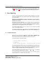
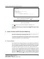
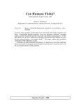
Figure 1: Example of an Instrumented Platform
1. a time domain plot of the power/energy, a
2. a table of statistics for power and energy which is written at the end of simulation but which can be dumped at intermediate points if desired.
There is also a C++ API so that user code can read accounting information for
generating custom reports (§5).
The POWER3 library supports two basic modelling modes:
1. In the mode/phase approach the average power consumption of an IP block
is set for a period of time (as per the POWER2 [1] library).
2. In the energy logging approach quanta of energy are logged into an account.
The two modes can be freely mixed, even within a component. For instance, typically we use the mode/phase approach for static power consumption and the energy logging approach for dynamic and wiring power.
In the mode/phase approach, power consumption is determined by the current
state of a component. A component is free to switch state at any time by invoking
library primitives (such as set static power). (There is no protection so a component can change the state of any other component for which it has the C++ object
pointer.) The state of the block is a pair that has phase and mode components.
There is no difference between phases and modes as far as the library is concerned. Phases are used to refer to short-term functional phases of a component
such as wait, read and compute. A mode is typically a particular DPM (Dynamic
Power Management) mode such as on, sleep or off). Both are characterized by
their standing power while in that mode/phase and the time duration before the
next mode/phase is adopted.
To support monitoring the power consumption of any SystemC module, the tracing
facilities take advantage of the hierarchy of a SystemC model. Indeed the energy
logged by a module with a summing observer is equal to its own plus that of its
sub-modules down to the leaves of the module tree. For example, in Figure 1 the
energy consumed by the module CLUSTER0 is equal to the total of expended by
its CPUs and its ROUTER.
The remainder of this document is organized as follows. Section 2 presents how to
model and instrument a TLM platform with power information. Section 6 presents
TLM Power 3.0 (CBG) User Manual
Version: CBG 3.2 Alpha
DRAFT MANUAL - UPDATED 1Q2015 - Rev f
6
MY Yasin, C Koch-Hofer, Pascal Vivet, DJ Greaves
how to monitor and generate traces from an instrumented TLM platform. Section 3 describes the options relating to physical layout modelling and bit transition
counting. Finally, §11 gives some implementation information about this library.
2
Power Modelling
Versions 1 and 2 of the library were based on power mode/phases for components (sleep, standby, active, etc.) whereas version 3 adds support for energy-pertransaction logging.
Mode/phase-based approach: The power consumption of a SystemC module is
defined for each operation mode and modules switch between modes and phases
throughout the simulation.
Energy-per-transaction approach: SystemC modules log an energy quanta for
each transaction they process, based on computations of how much energy is
used. For instance, for a bus the energy per transaction may include a component
proportional to the burst length field in the generic payload.
The examples folder contains power3demo which uses the TLM generic payload
and the energy logging approach.
The examples folder contains tlm tac which uses the mode/phase approach. This
may no longer compiles properly in the pre-beta release of the POWER3 library ?
2.1
Customer Accounts
New in release 3.1 is the customer id that is associated with a ‘no children’ style
observer. A customer identifier is created by a typical component such as a core,
but the observer will record energy credits from all over the system.
A customer identifier is declared as follows
sc_pwr::pw_customer_id customer_id;
// constructor:
customer::customer_id(sc_module *, const char *user_name, int idx=-1)
It is automatically initialised with a unique internal identifier by its constructor in the
library. A coupled observer is also created. It must be associated with a SystemC
module for callback reasons but it has no further association with that component.
It has a user name and optional index for presentation purposes.
The customer identifier can be passed in to the record energy use main logging
API for energy to be credited under the account.
The customer identifier can be carried arround easily in our version of the generic
payload provided this is enabled in the macro setting.
TLM Power 3.0 (CBG) User Manual
Version: CBG 3.2 Alpha
DRAFT MANUAL - UPDATED 1Q2015 - Rev f
7
MY Yasin, C Koch-Hofer, Pascal Vivet, DJ Greaves
// Put a customer number in a transaction
PW_TLM_PAYTYPE trans;
trans.set_customer_acct(customer_id);
// At various places, use the following to record energy, not only against
// the local structural observers, but also against the customer noted in
// the payload.
record_energy_use(op_energy, &trans);
When customer identifiers are in use and a call to record energy use is made
without a customer identifier being given, the energy is logged to the local structural accounts AND to a special customer account provided by the library called
‘anonymous’. (The grand total figure is unaffected - whatever is logged is recorded
in this exactly once always.)
2.2
Physical Data Types
As in the SystemC SC TIME class, the TLM Power library implements classes that
define units for manipulating power, energy voltage, length and area values (§2.2).
It also defines some base classes for defining the power consumption and the
running mode of a module during a simulation.
2.3
Physical unit: Power in Watts
Class PW POWER is used to represent electrical power value (internal representation is internally a double and a PW POWER UNIT). A pw power unit is an enumerate type representing power physical unit: pw fW for femto-watt, pw pW for pico-watt,
..., pw WATT for watt.
The default power resolution is 1 pico-watt. The power resolution can only be
changed by calling the function pw set power resolution(double). This function
can only be called during elaboration, cannot be called more than once and cannot
be called after constructing an object of type pw power with a non-zero power value.
The value of the double argument shall be positive and shall be a power of 10. A
report of severity SC ERROR is thrown if these rules are not respected. The value
of the power resolution is given by the pw get power resolution() function.
The constant pw ZERO POWER represents a power value of zero. The static method
max() returns the maximal power value according to the power resolution.
All the traditional arithmetic, relational, equality and assignment operators are supported. A report of severity SC WARNING or SC ERROR is thrown when the
result of an arithmetic is not coherent:
When an overflow is detected the resulting value is equal to the maximal power
value, when an underflow is detected the resulting value is equal to zero, when a
division by zero is detected the resulting value is equal to the maximal power value.
TLM Power 3.0 (CBG) User Manual
Version: CBG 3.2 Alpha
DRAFT MANUAL - UPDATED 1Q2015 - Rev f
8
MY Yasin, C Koch-Hofer, Pascal Vivet, DJ Greaves
2.4
Physical unit: Energy in Joules
Much like the pw power class, the class pw energy is used to represent electrical energy values and has the same functions. The default energy resolution
is 1 pico-joule and the physical unit is also represented by an enumerated type
pw energy unit (i.e. pw fJ for femto-joule, pw pJ for pico-joule, ..., pw JOULE for
Joule).
2.5
Physical unit: Length in Metres
Much like the pw energy class, the class pw length is used to represent physical
length and has the same functions. The default energy resolution is 1 pico-metre
(SHOULD BE micron by default) and the physical unit is also represented by an
enumerated type pw energy unit (i.e. pw fm for femto-metre, pw pm for pico-metre,
..., pw METRE for metre).
2.6
Physical unit: Area in Metres2
Much like the pw length class, the class pw area is used to represent layout area
and has the same functions. The default area resolution is the square micron and
the physical unit is also represented by an enumerated type pw area unit (i.e.
pw squm for square microns, pw sqcm for square centimeters, pw sqmm for square
millimetres and pw sqm for square metres.
2.7
Physical unit: Voltage in Volts
Much like the pw energy class, the class pw voltage is used to represent potential difference values and has the same functions. The default energy resolution
is 1 pico-volt (should be VOLTs) and the physical unit is also represented by an
enumerated type pw energy unit (i.e. pw fV for femto-volt, pw pV for pico-volt, ...,
pw VOLT for volt).
TODO: THESE UNITS SHOULD ALL BE FULLY DOCUMENTED IN TABLES.
Finally, some arithmetic operators using these various classes plus the SC TIME
class are provided for performing multiplication and division with different physical
quantity parameters.
TLM Power 3.0 (CBG) User Manual
Version: CBG 3.2 Alpha
DRAFT MANUAL - UPDATED 1Q2015 - Rev f
9
MY Yasin, C Koch-Hofer, Pascal Vivet, DJ Greaves
2.8
Instrumenting a SystemC module
// Approach 1: inheriting the pw_module
class FOO:
public sc_module,
public pw_module
{
public:
SC_HAS_PROCESS(FOO);
FOO(const sc_module_name& p_name, int width):
sc_module(p_name),
pw_module("config.txt")
{
}
// Approach 2 : having a reference to a power base
... details missing
Class pw module base should be listed as a base class of a SystemC module that
is instrumented for power monitoring. The SystemC module should also inherit
sc module as usual.
The constructor for a module, such as a RAM or CPU, is typically provided with
physical size parameters (bit width, number of words, and so on) and it should
can use these in setting its placement and power profile. These instantantiations
parameters can be combined with values read from a technology/instance file and
supply voltage settings to determine standing powers and transaction energies.
2.9
Technology/Instance configuration file.
Components that inherit pw module may import a technology/instance configuration file to assist with setting their physical size, allocating power consumption to
transactions and naming different power modes and phases.
Normally a defaulting value for the name of the file to be read is given by the SystemC ‘kind’ of the component. The default name is power config-modulekind.txt
where ’modulekind’ is the kind identifier.. This approach is suitable where all of the
per-instance variations are controlled by the constructor of the SC MODULE and
nothing needs reading from the configuration file on a per-instance basis. Values
read from the file can be modified by the constructor using, for instance, other
parameters read from user globals or module parameters, such as the size of a
RAM.
When the pw module constructor is called with no arguments, the module should
implement the ‘kind’ method (i.e. module type name) that returns a constant string
whose name is used as the basis for the file to be consulted.
The name of the file to read can alternatively be specified as an argument to the
constructor and this again may be based on the SystemC kind() or on the SystemC instance name name(). Generally the latter is not needed since each instance should be identically parameterised in terms of technology constants, even
if different in per-instance parameters, such as size.
TLM Power 3.0 (CBG) User Manual
Version: CBG 3.2 Alpha
DRAFT MANUAL - UPDATED 1Q2015 - Rev f
10
MY Yasin, C Koch-Hofer, Pascal Vivet, DJ Greaves
An XML version of the file may be supported in the future.
The entries in the file have the following purposes:
• Mode Line: Defines a dynamic power mode and phase.
• Voltage Line: Gives the supply voltage for which the powers in the mode line
are correct. Variation w.r.t. supply squared is assumed. If this line is omitted
a one volt supply is assumed.
• Size Line: Gives the physical dimensions of a module: a width and length
pair. Generally there is no difference between width and length and they are
mostly just multiplied to give the module area.
• Location Line: Gives the X/Y coordinates of a module if detailed placement is
being used (currently unimplemented; the lowest-common parent approach
is used instead).
The syntax of a configuration file respects the following pseudo-EBNF grammar.
::=
MODELINE | VOLTAGELINE | SIZELINE # comment
VOLTAGELINE
::=
v voltage
SIZELINE
::=
s length length
MODELINE
::=
m MODE [ PHASE ] DYNAMIC STATIC
MODE
::=
string
PHASE
::=
string
DYNAMIC
::=
power
STATIC
::=
power
string
::=
[ a-zA-Z . ]+
voltage
::=
floating-literal VOLTAGEUNIT
length
::=
floating-literal LENGTHUNIT
power
::=
floating-literal POWERUNIT
VOLTAGEUNIT
::=
fV | pV | nV | uV | mV | V
LENGTHUNIT
::= | nm | um | mm | cm | m
POWERUNIT
::=
fW | pW | nW | uW | mW | W
line
A limitation of the parser, currently used, is to not support spaces between the
floating-literal and the unit token of the power rule.
2.10
Chip/Region Name
Every component is nominally on a given chip which has a textual name. It is
sometimes convenient to use this mechanism on a finer grain and hence the name
is sometimes a region name rather than a chip name.
A component is sometimes conveniently allocated a chip/region name as an optional parameter to the area setting calls. Otherwise the specific set chip region(std::string
&) method should be called in the current region. Either approach will recursively
set the chip/region for the child objects that are unset.
All regions or chips that are supposed to be different must be given different names
by the user.
TLM Power 3.0 (CBG) User Manual
Version: CBG 3.2 Alpha
DRAFT MANUAL - UPDATED 1Q2015 - Rev f
11
MY Yasin, C Koch-Hofer, Pascal Vivet, DJ Greaves
These calls also enable the chip/region of the current component to be given. If no
name is given then the name of the instantiating parent is used. At the top level, if
no name is give, then the SystemC name() is used.
Chip names and other layout details are reported in the file physical.txt. The
user can change the name of this file by assigning his own string to this global:
const char *sc_pwr::phy_report_name = "physical.txt";
2.11
Voltage Scaling
Each component has an associated supply voltage. A component can adjust its
local supply voltage using either of the following two calls:
void set_vcc(const pw_voltage&,
bool update_children=true);
void set_vcc(double, pw_voltage_unit, bool update_children=true);
By default these will update the supply voltage to all child components on the same
chip or region. Note that this will not be the complete chip/region if this call is not
made at the top-level component of that chip or region.
Energy consumption is typically proportional to supply voltage squared. Performing a floating-point multiplication for every energy logging operation is expensive
and so the energy quanta are typically held pre-scaled in the users component
model and recomputed only when the supply voltage (or other PVT component)
changes.
To facilitate this, in the user’s constructor, the device should first set its supply voltage if it wishes, or else use the voltage inherited from its parent. Then it should call
a locally-defined function called recompte pvt parameters() which is a locallysupplied override to a virtual function (defined in sc pwr::pw module base). The
POWER3 library will call this function whenever there is a supply voltage or other
PVT change. The user’s implementation of this function should recompute the energy quanta associated with transactions to be logged in subsequent transactions
with that supply voltage. For example.
void myram::recompute_sram_pvt_parameters() // Call when Vcc is changed etc..
{
sc_time l_latency = sc_time(0.21 + 3.8e-4 *sqrt(float(m_bits)), SC_NS);
pw_power l_leakage = pw_power(82.0 * m_bits, PW_nW);
m_read_energy_op = pw_energy(5.0 + 1.2e-4 / 8.0 *m_bits, pw_energy_unit::PW_pJ);
std::cout << name() << " " << m_bits/8 <<
" byte SRAM: leakage_power=" << l_leakage.round3sf() << "\n";
set_static_power(l_leakage);
m_write_energy_op = 2.0 * m_read_energy_op; // rule of thumb!
m_llsc_excess_energy_op = m_write_energy_op;
When using mode/phase modelling, the values in the underlying table are multiplied by the ratio of the current voltage to their nominal voltage squared before
being returned to the user or installed in accounts.
TLM Power 3.0 (CBG) User Manual
Version: CBG 3.2 Alpha
DRAFT MANUAL - UPDATED 1Q2015 - Rev f
12
MY Yasin, C Koch-Hofer, Pascal Vivet, DJ Greaves
2.12
Logging Power Consumption: Mode/Phase Approach
The mode/phase-based power consumption approach deals separately with static
and dynamic power.
The mode/phase-based power consumption is typically used for static power dissipation. It can also be used for dynamic power when per-transaction energy is
not being used. But when dynamic power is being modelled on a per-transaction
basis, it is appropriate to set the dynamic power of the mode/phase to zero. This
can be achieved by simply not calling set dynamic power in that component.
The mode/phase-based power consumption of a component is normally announced
by that component by calling one of the following convenience functions which determine the current standing powers (static and dynamic):
1. the dynamic power consumption is set using SET DYNAMIC POWER ( PW POWER &),
2. the static power consumption is set using SET STATIC POWER ( PW POWER &),
3. the mode of power consumption is set using SET POWER MODE ( STRING &),
4. the phase of the power mode consumption is set using SET POWER PHASE ( STRING
&),
5. the phase and power mode can both be set at once using UPDATE POWER ( STRING
& MODE , STRING & PHASE ).
Note that the full signature to SET STATIC POWER is
void set_static_power(const pw_power&, int l_acct = PW_ACCT_STATIC_DEFAULT);
and the body of SET DYNAMIC POWER does the same thing as SET STATIC POWER
but with the account number being PW ACCT DYNAMIC DEFAULT. Other account numbers may be freely used for other purposes.
The power mode and phase are strings used for associating a power consumption
to any computation mode and phase of a module. Some frequently used power
modes and phases are pre-defined: PW MODE ON, PW MODE OFF, PW PHASE WAIT,
....
The example in Figure ?? presents how to associate different power information to
the different computation modes and phases of the FOO module.
When the power behavior of a model just needs to know the current mode and
phase, it is possible to use the class PW MODULE. This class is an extension of the
class PW MODULE BASE.
As a running example, these different facilities were used for modelling the power
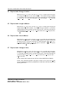
consumption of a simple platform based on the TLM TAC router (§8).
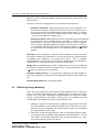
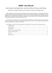
As illustrated by the example of Figure 2 the same behavior as the one of Figure reffig:three can be written more shortly using the class pw module. Indeed,
the associations defined in the configuration file can be used with the method UP DATE POWER for setting the power information.
TLM Power 3.0 (CBG) User Manual
Version: CBG 3.2 Alpha
DRAFT MANUAL - UPDATED 1Q2015 - Rev f
13
MY Yasin, C Koch-Hofer, Pascal Vivet, DJ Greaves
Figure 2: Simple TAC Platform.
tac_response tac_multiport_router::b_transport(tlm_generic_payload &trans, sc_time &delay)
{
unsigned int len = trans.get_data_length();
... // Main body of the behavioural model
sc_time activity_time = ...;
delay += lt_activity_time; // Or use qk_inc to perform this addition
#ifdef TLM_POWER3
// bit_width has been set in the constructor... etc
sc_energy energy_cost = pw_energy((double) (5 * len), pw_energy_unit::PW_pJ);
pw_module_base::update_energy(energy_cost, lt_activity_time);
#endif
}
Figure 3: Energy-based instrumentation of TLM call (intra-module component).
The power values associated to a power mode can also be accessed through the
GET DYNAMIC POWER and the GET STATIC POWER methods. For example, these
methods can be used with the basic methods of the class pw module for describing
the complex part of a power behavior and still using the method UPDATE POWER
for the simple part.
2.13
Logging Power Consumption: Transaction Energy Approach
Power consumption associated with a transaction consists of two components:
1. Inter-module power (proportional to wiring length and number of bits in transistion)
2. Intra-module power (associated with internal operation inside the component.
Figure 3 is a simple illustration of the the approach where transactional energy
consumption internal to a module is logged for each transaction. For each transaction, the transport method logs both the intra-module energy consumed and the
activity time for which is has been busy.
The cost-per-bit is multiplied by the transaction length to model its dynamic energy
use. This energy is is passed to update energy as the first argument where it is
TLM Power 3.0 (CBG) User Manual
Version: CBG 3.2 Alpha
DRAFT MANUAL - UPDATED 1Q2015 - Rev f
14
MY Yasin, C Koch-Hofer, Pascal Vivet, DJ Greaves
trans.pw_set_origin(this, PW_TGP_ADDRESS | PW_TGP_ACCT_SRC, &frontside_bus);
initiator_socket->b_transport(trans, delay);
trans.pw_terminus(this);
}
Figure 4: Energy-based instrumentation of TLM call (inter-module component).
logged.
The second argument is either SC TIME ZERO if utilisation logging is not required
or appropriate or else the time for which the component has been active since
the last call to update energy. Using loosely-timed models the activity time is
either the time accumulated in the current component or the time accumulated
between call and return from the transport method according to whatever definition
of utilisation is required.
The observers, currently, add the energy part to the dynamic energy aggregate
and time part to utilization aggregate. Thus, at any instant, (utilization/simulated
time) gives the percentage of time that a module has been busy. In the future one
could record utilization per quantum to observe busy periods for a module so as to
spread its work load over time or over number of modules if needed.
In the TLM POWER3 library, the energy is scaled by the standing supply voltage
squared unless the optional noscale=true parameter is passed to update energy.
Figure 4 illustrates a basic form of the companion approach where transactional
energy consumption consumed in wiring is logged. This is the inter-module energy.
See § refsec:tlmwiringenergy for full details.
2.14
Logging Length and Area
A component can describe its physical size in its constructor using one of the
following TLM POWER3 calls:
//Set actual dimensions of current component
void set_fixed_dimensions(pw_length x, pw_length y, const char *chipname=0);
// Set additional area of current component
void set_excess_area(pw_length x, pw_length y,
float max_aspect_ratio=2.5, const char *chipname=0);
void set_excess_area(pw_area a, float max_aspect_ratio=2.5, const char *chipname=0);
The former sets the actual dimensions of the current component, leading to a
TARDIS warning if this is smaller than the sum of its components.
The excess area calls describe the additional area of the current component beyond that of the sum of its child components. The component is assumed to be
flexible in shape from square up to an oblong of maximum aspect ratio specified.
These calls also enable the chip/region of the current component to be given. If no
name is given then the name of the instantiating parent is used. At the top level, if
no name is give, then the SystemC name() is used.
TLM Power 3.0 (CBG) User Manual
Version: CBG 3.2 Alpha
DRAFT MANUAL - UPDATED 1Q2015 - Rev f
15
MY Yasin, C Koch-Hofer, Pascal Vivet, DJ Greaves
class FOO:
public sc_module,
public pw_module
{
public:
SC_HAS_PROCESS(FOO);
FOO(const sc_module_name& p_name, int width):
sc_module(p_name),
pw_module("config.txt")
{
set_excess_area(pw_length(50.0 * width, PW_um),
pw_length(5.0 * width, PW_um)); // or from tech file
}
};
Figure 5: Length and area annotations pw module.
pw_excess_area(PR_MICRON(40),PR_MICRON(40), 0.25);
Figure 6: Size Annotation.
Figure 5 illustrates the basic approach to logging a component’s area.
Although X/Y dimensions are used to log area, TLM POWER3 assumes that a
component can freely change its aspect ratio from 1:1 to 2:1 to obtain a good
layout unless ...
3
Layout, Distance and Bit Transition Modelling
Both net-level interconnects and TLM transactions model data moving some distance with associated charge and discharge of the nets.
It is important not to model both the charge and discharge of a given net, otherwise
energy costs will be double counted. We adopt the approach of only counting the
zero to one transition of a net as energy consuming.
3.1
Place and Route
Every component may compute and register its excess physical size in two dimensions. The excess size is how much more area the component has that the sum
of its sub components. A component may also register its absolute size, in which
case the sum of its components is ignored, but a warning is issued if it behaves
like a TARDIS, having more internal size (on the same chip) than outside size.
Commonly, some models will include components that do not physically exist inside
them. For instance, a DRAM controller might instantiate the DRAM chips inside the
controller rather than bothering to route the connections up through the top level
of the SoC. TLM POWER3 supports this style of modelling using the concept of
chip names. Any component (sc module) can be specified as having a separate
chip name. Its area and power are not included in that of its parent component.
TLM Power 3.0 (CBG) User Manual
Version: CBG 3.2 Alpha
DRAFT MANUAL - UPDATED 1Q2015 - Rev f
16
MY Yasin, C Koch-Hofer, Pascal Vivet, DJ Greaves
Moreover, the inter-chip wiring model is applied to transactions and nets that cross
between chips.
Placement (and hence wiring distance) can be determined in two ways:
• Geometric Placement. With geometric placement, every component is allocated 2-D co-ordinates inside the perimeter of its parent. Geometric placement is based on heuristic algorithms based on random numbers. It can give
unpredictable results and users should interpret results only after making
several runs with different random seeds.
• Rentian Placement. With Rentian placement, no actual placement co-ordinates
are determined and no random number generation is required. Instead,
wiring distances are given according to Rent’s Rule based on component
area. The lowest-common module that contains the two-ends of an interconnect is found by walking up the module hierarchy until a common SC MODULE
is encountered. The wiring distance is then predicted from the area of that
module.
Placement. Every component is allocated 2-D co-ordinates inside the perimeter
of its parent. Rather than performing an accurate placement based on geometric
tessellations each component is assumed to be a square. This is a simplistic
approach which is correct in terms of area but not suitable for physical manufacture.
A png plot file is created for the placement to help visualisation.
Wiring area. An additional wiring swell is added to the area of each component
based on the number of internal connections it has. Internal connections may be
sc signals or TLM sockets or user-defined.
Geometric Wiring distance. Using geometric modelling, the wiring length between two components is computed as the Manhattan distance between their centres.
Rentian Wiring Distance. Using rentian wiring, ...
3.2
TLM Wiring Energy Modelling
Given that a transaction takes place between two components that are part of a
layout, the distance information can be combined with the number of transitioning bits in an envisaged, underlying bus implementation, to compute the wiring
energy associated with the transaction. However, there are a number of general
considerations to including in a wiring energy model for TLM:
1. Although a single transaction (generic) payload may typically be transferred
on a round trip basis from originator, through the bus, NoC and server components back to the originator, not all fields will be active in the underlying
bus implementation at each hop.
2. Some hops may be off-chip PCB traces with associated pads that have different energy cost per unit length compared with on-chip interconnects. On-chip
connections are typically unidirectional but off-chip connections are sometimes bi-directional using tri-state drivers.
TLM Power 3.0 (CBG) User Manual
Version: CBG 3.2 Alpha
DRAFT MANUAL - UPDATED 1Q2015 - Rev f
17
MY Yasin, C Koch-Hofer, Pascal Vivet, DJ Greaves
3. The wiring energy can be charged to the source or destination component or
be separately accounted.
4. The cost of bit-transition counting is high on most host workstations, so detailed bit toggle counting should be replaced with estimated average values
as an user option.
In a simple example, the originator will complete the address field of the payload
and, for writes, also the data and byte-enabled fields. The intermediate components will forward these fields, perhaps with minor changes (e.g. adddress space
manipulations at bus bridges or VM units) to the destination. The destination will
reply with a low-cost acknowledgment for a write and with the data for a read.
The PW TLM PAYLOAD sub-library is provided with the TLM POWER3 library
as an extra component for estimating wiring energy when using the OSCI TLM2.0
TLM library. It has several modes of operation that are controlled by the preprocessor variable PW TLM PAYLOAD.
To use the PW TLM PAYLOAD LIBRARY, the sockets provided by TLM2.0 must
be defined with an additional type parameter that extends the generic payload and
the socket use sites must be augmented with additional library calls, as described
below. However, the user might typically define their own CPP macros that integrate the TLM 2.0 socket operations with the PW TLM PAYLOAD library calls.
The third generic argument to socket definitions must be provided and defined
as PW TLM TYPES. The signatures to the transaction methods also need to be
defined to use PW TLM PAYTYPE instead of the standard generic payload.
These two changes have no effect when PW TLM PAYLOAD is set to zero since
the macros are then defined as their defaults, but for other values the extended
generic payload is used.
//Providing the third template argument to a socket:
tlm_utils::simple_initiator_socket<tracedriven_core_btlm, 64, PW_TLM_TYPES> initiator_socket;
//Using the extended generic payload in the transaction methods:
void b_access(PW_TLM_PAYTYPE &trans, sc_time &delay)
The three primitives used for bus energy modelling are pw set origin, pw terminus
and pw log hop calls. These mark the beginning, intermediate steps and end of a
TLM payload trajectory.
void pw_set_origin(sc_module *where, uint flags=0, bit_transition_tracker *transition_reference=0);
pw_handle *pw_log_hop(sc_module *where, uint flags=0, bit_transition_tracker *transition_reference=0);
void pw_terminus(sc_module *where);
The first argument where is the this pointer for the current component. This is
used to track the path through the system.
The second argument is the flags. Most flags are sticky and apply to subsequent
hops that do not change that flag. In particular, if the flags argument is zero for the
next hop then nothing has changed and the next hop has the same properties as
the previous hop.
TLM Power 3.0 (CBG) User Manual
Version: CBG 3.2 Alpha
DRAFT MANUAL - UPDATED 1Q2015 - Rev f
18
MY Yasin, C Koch-Hofer, Pascal Vivet, DJ Greaves
Name
PW TGP ADDRESS
Description
The address field contains
live data.
The data field contains
live data.
The
byte lanes contain live data.
The address and data fields contain
live data which are sent over a common bus.
No fields contain live data
(apart from command + response)
PW TGP DATA
PW TGP LANES
PW TGP MUXD AD
PW TGP NOFIELDS
Notes
Sticky. &
Sticky. &
Sticky. &
Sticky. &
Sticky. &
Table 1: Active payload field PW TGP XXX
Name
PW TGP ONCHIP
PW TGP OFFCHIP
Description
The next hop uses the on-chip
wiring costs.
The next hop uses the off-chip
wiring costs.
Notes
Sticky. &
Sticky. &
Table 2: Bus energy model PW TGP XXX
The third argument is a bus reference. Every transaction is considered to take
place over a bus and a bus is a generic set of wires modelled with a bit transition tracker.
Wires present that are not used consume no energy, so it is not important to customise the instance of a bus to its use (e.g. the bus from CPU to memory has
address and write data whereas the return bus has just read data). The bus reference is needed so as to check which physical nets are transitioning with respect to
their previous value.
3.3
TLM Wiring Energy Modelling Computation
The formula used for energy consumption is a straightforward product of three
numbers:
1. the length of the current hop (in millimetres) (from Rentian or other wiring
estimator: §3.1)
2. the number of bits that have transitioned (measured or estimated: §3.5)
3. the energy per millimetre per transition for the wiring style being used (taken
from technology file)
3.4
TLM Wiring Energy Modelling Flags
The flags field is a bitwise OR of one or more of the PW TGP XXX flags. Certain flags are mutually exclusive, with only one from each group being allowed.
TLM Power 3.0 (CBG) User Manual
Version: CBG 3.2 Alpha
DRAFT MANUAL - UPDATED 1Q2015 - Rev f
19
MY Yasin, C Koch-Hofer, Pascal Vivet, DJ Greaves
Name
PW TGP SRC ACCT
PW TGP DEST ACCT
PW TGP CKP ACCT
Description
The energy for the next hop(s)
should be debited to the current
component.
The unaccounted wiring energy
so far should be passed on to a
subsequent component.
The unaccounted wiring energy
so far should consolidated to the current
or originating component depending on
the pertaining sticky in methods.
Notes
Sticky.
Sticky.
Non-sticky.
Table 3: Bus energy accounting methods PW TGP XXX
3.5
Transition Density Estimations
Rather than measuring the bit hamming distances on every operation, which is expensive,
the library uses a so-called ¡b¿confidence switcher¡/b¿. This is a template that fully executes
a function some first number of times, N , (1000 or so), but after that the average of these
first calls is returned instead. This greatly saves execution time for the function.
Two refinements are applied to this basic approach. 1. To avoid warm-up effects, the
average of first N calls is disregarded and the second N worth of calls is used for calls 2N
onwards. 2. To check for non-stationary behaviour, after 2N calls, the underlying function is
called once in every N applications and the result compared with the average. If it is out of
kilter a warning is printed ... (Ed: please be more precise here!).
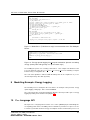
3.6
TLM Wiring Energy Modelling Example (Blocking Style)
We will first explain its use with the blocking TLM coding style assuming that the TLM is
forwarded through one or more passthough sockets in the NoC or bus model to an endpoint
(e.g. a RAM) and returned the same route.
Here is the basic code for an annotated initiator. Note that different fields in the bus are
active depending on whether it is a read or a write transaction.
// Example code for a blocking TLM initiator:
if (R) trans.set_read(); else trans.set_write();
trans.pw_set_origin(this, PW_TGP_ADDRESS |
PW_TGP_ACCT_SRC |
((R)?0:PW_TGP_DATA|PW_TGP_LANES),
&forward_bus);
initiator_socket->b_transport(trans, delay);
trans.pw_terminus(this);
The forward bus should be defined in the initiator class using
sc_pwr::tlm_bit_transition_tracker forward_bus;
and initialised in the constructor by passing it the this pointer of the initiating component.
Two calls to pw log hop are required in a passthrough component to register the forward and
backward operations, but flags and bus arguments are not normally needed (see below):
TLM Power 3.0 (CBG) User Manual
Version: CBG 3.2 Alpha
DRAFT MANUAL - UPDATED 1Q2015 - Rev f
20
MY Yasin, C Koch-Hofer, Pascal Vivet, DJ Greaves
// Example code for a passthough TLM bus or NoC component:
void :b_transport(int id, PW_TLM_PAYTYPE &trans, sc_time &delay)
{
pw_handle *h = trans.pw_log_hop(this); // First call - on entry to the component
h->record_energy_use(...)
... other code
// No special decorations are neede around the passthough operation
passthrough_init_socket->b_transport(trans, delay);
... other code
//Second call, at return operation (the same handle will be returned and can be ignored).
trans.pw_log_hop(this);
h->record_energy_use(...)
}
The endpoint is much like a hop, but this hop will generally change the active fields. Also,
unless using tri-states on a PCB, a different bus should be provided to model separate read
and write data busses in a SoC.
// Example code for a blocking TLM end point that is to return a payload
// with different fields active and on a separate read bus.
tlm::tlm_command cmd = trans.get_command();
trans.pw_log_hop(this,
(cmd==tlm::TLM_READ_COMMAND ? PW_TGP_DATA: PW_TGP_NOFIELDS) | PW_TGP_ACCT_CKP,
&read_return_bus);
3.7
TLM Wiring Energy Modelling Example (Non-Blocking Style)
This text is missing. TODO.
3.8
Non-TLM Wiring Energy Modelling Example
Energy use in individual net transitions that are not part of a TLM payload or which use
non-standard TLM interfaces can be logged as follows.
This text is missing. TODO.
4
Physical Reports
Physical report files may be written by the library, including area and layout.
A generated file, default name physical.txt, describes the module hierarchy by voltage
scaling domain and gives area at each level.
5
C++ API
Each annotated component (type sc module) has a power module of type pw module base
as a base. The basic form of C++ API is provided through the methods of this base class.
This contains static information about component size and varying information such as the
current mode/phase power for each account.
At any point we can read off the total energy used so far:
TLM Power 3.0 (CBG) User Manual
Version: CBG 3.2 Alpha
DRAFT MANUAL - UPDATED 1Q2015 - Rev f
21
MY Yasin, C Koch-Hofer, Pascal Vivet, DJ Greaves
const sc_pwr::pw_energy l_global_energy = pw_stat_observer_base::get_global_energy();
However, each component has a summing or standalone (or both) observers, which provide
cummulative data for that component (and also its children for the summing variant). The
observer API should be used for reading energy use.
// How to get a handle on an observer for the current SC_MODULE:
sc_pwr::pw_stat_observer_base *it = pw_get_observer(this, sc_pwr::no_children);
// How to get a handle on an observer for the current SC_MODULE and its children:
sc_pwr::pw_stat_observer_base *it = pw_get_observer(this, sc_pwr::sum_children);
// How to get a handle on a global summing observer for the complete system:
sc_pwr::pw_stat_observer_base *it = pw_get_observer(0, sc_pwr::sum_children);
sc_start();
...
// At any point then we can print as follows:"
std::cout << "Energy in account " << it->get_global_name(0)
<< " is " << it->get_energy(0) << "\n";
std::cout << "Energy in all accounts " << it->get_energy() << "\n";
6
Tracing Facilities
Three different forms of trace report can be generated with the TLM POWER3 library. These
include SyLK, VCD, and TEXT. All three include power and energy consumption, utilisation.
Transaction tracing is now being added ...
The library will automatically add up the power and energy used globally but the top module
must be traced using one of the trace methods to see this global total in the associated trace
file.
Individual sub-systems may also be traced by selecting other points in the hierarchy to trace
and passing the associated component as an argument to the power trace function. Each
item traced generates a fresh set of totals that include that item and, in common use, all of
its children. So the consumption of a component can be included in more than one trace
total of a similar form by tracing it and one or more of its parents or by tracing two or more
of its parents.
There are two main forms out output trace file. Firstly, a VCD 6.1 trace file recording the
power variations along a simulation. Secondly, a textual file or a SYLK (SYmbolic Link) file
gathering different statistics about the power and energy consumptions.
6.1
VCD Traces
A VCD trace file records a time-ordered sequence of instantanious power values during simulation. Energy plots would be monotonic and not that pretty so are not currently supported.
The VCD trace file can be created and opened by calling function pw create vcd trace file.
A trace file may be opened during elaboration or at any time during simulation. Energy observers can be traced by calling function pw trace. A trace file shall be opened before
values can be traced to that file and values shall not be traced to a given trace file if one or
TLM Power 3.0 (CBG) User Manual
Version: CBG 3.2 Alpha
DRAFT MANUAL - UPDATED 1Q2015 - Rev f
22
MY Yasin, C Koch-Hofer, Pascal Vivet, DJ Greaves
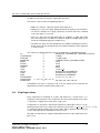
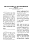
Figure 7: TAC Power Consumption Waveform.
more delta cycles have elapsed since opening the file. A VCD trace file shall be closed by
calling the close() method of the trace object at the end of the simulation.
There are two styles of VCD plotting for energy events: averaging and decaying. For the
decaying form of tracing, new energy log events are upwards impulses that then decay. The
VCD tracer accumulates new energy while geometrically writing off the old energy. For the
averaging form of tracing, we render energy events as rectangles with area proportional to
energy use. Their height is the average value in that interval. The rectangle for an energy
quanta could possibly best be centred around its log event, but we draw the rectangle ending
at the log event. In both styles, phase/mode changes are rendered as rectangles whose
duration corresponds to the interval in that phase/mode.
The decaying plot again represents energy as area. This is computed by scaling the initial
height of the energy impulse inversely with the decay rate. The time constant for the decay
is set as ... XXX.
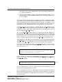
Figure 7 shows the waveform diagram of the VCD trace file generating by the simulation of
a modified simple TAC platform. This uses phase/mode annotations only. As illustrated by
the code of Figure 10, the main() method was modified to create the trace file and indicate
the modules to monitor. TODO: Can’t we capture them all by default?
The first call to the function pw trace generates the first waveform of the Figure 7. This
waveform shows that the power of the module TOP is equal to the sum of the power consumed by all its sub-components (router, timer, ...). Finally, the second call to the function
pw trace generates the second waveform of the Figure 7 which is equal to the power consumed by a TAC multiport router.
Note, you should put your viewer into analog rendering mode in your waveform viewer for
the VCD data generated by this tracer.
6.2
VCD Trace Table Output
The VCD generator accepts an optional second argument - a filename to use for a textual
plot file. This can be used for gnuplot rendering of the VCD waveforms or for other purposes.
It has columns of numeric data separated by tab characters with the timestamp as the first
field. This table can include exactly the same data as in the VCD file but is not in VCD
format.
To plot the global total you need to apply trace to the top of each tree of modules with
TLM Power 3.0 (CBG) User Manual
Version: CBG 3.2 Alpha
DRAFT MANUAL - UPDATED 1Q2015 - Rev f
23
MY Yasin, C Koch-Hofer, Pascal Vivet, DJ Greaves
sum children mode (most designs only have one tree (i.e. they are not forests of SystemC
modules)).
A plot col argument to the trace method allows alters the layout of the plot file entries for
that trace as folows:
// Gnuplot expects whitespace-separated columns of data and specific
// columms can be extracted using commands such as
// gnuplot> plot "plot.dat" using 1:2 title ’DRAM’, "plot.dat" using 1:3 title ’CPU’
typedef enum { DoNotPlot, PlotEachAccount, PlotCombinedAccounts } plot_control_t;
6.3
VCD Plot Future Improvements?
The VCD plot legends contain the word energy but the plot is power.
Perhaps the same plot control t should be supported for the VCD output itself... Then all
accounts within an observer can be summed and shown as one line on the VCD graph.
6.4
Textual Statistics File
A text file gathering different statistics about power consumption can be created and opened
by calling function pw create txt trace file. It may be opened during elaboration or at
any time during simulation. The modules to monitor are defined by calling function pw trace.
A textual file shall be opened before the power changes of the monitored modules and shall
be closed by calling the close() method of the trace object at the end of the simulation.
As for the VCD trace file, the code of the main() method was modified for generating a
textual file and indicating the modules to monitor. The first part of this file (Figure ??)
contains the elapsed simulation time used for computing the different power statistics and
the three following arrays:
• The first array contains the dynamic and static energy (in Joules) consumed by the
monitored modules. The percentage values indicate the dynamic or static energy
consumed of a module compared to its global consumption.
• The second array contains the same information as the one before but for power
consumption (in Watts).
• The third array gives the power contribution (in percentage) of the monitored modules.
The second part of the generated textual file details the power consumption of each module.
For example, Figure ?? illustrates the power information given of the first memory bank. As
before, this section is composed of three arrays where the column module is replaced by
the power modes (e.g. ...‘ON’) and phases (e.g. ‘IDLE’, ‘READ’ ...) used by this memory
during the simulation.
6.5
SYLK Statistic File
As for the textual trace file, the SYLK (Symbolic LinK) trace file gathers different statistics
about power consumption. The functions for managing this format of trace file is the same
as the ones for the textual trace file, except their suffix names TXT TRACE FILE is replaced
by SLK TRACE FILE. The main advantage of this trace file format is to be supported by most
of the spreadsheets.
TLM Power 3.0 (CBG) User Manual
Version: CBG 3.2 Alpha
DRAFT MANUAL - UPDATED 1Q2015 - Rev f
24
MY Yasin, C Koch-Hofer, Pascal Vivet, DJ Greaves
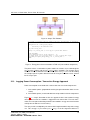
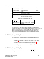
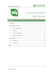
Figure 8: SYLK Statistics.
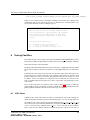
As presented in Figure 8, the statistics generated are the same as the one gathered in a
textual trace file. The first array gives the power consumption, the energy consumption and
the power contribution of each monitored modules. The second array gives details about
the power consumption of each module.
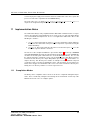
7
7.1
Options
Net Transitions
The net-transition monitor may be enabled to compute the number of wires that change
value in a transaction. This behaviour typically follows well-known patterns, and so energy
useage based on net-transitions is not often required to be modelled. However, this facility
helps calibrate and confirm such models.
TLM Power 3.0 (CBG) User Manual
Version: CBG 3.2 Alpha
DRAFT MANUAL - UPDATED 1Q2015 - Rev f
25
MY Yasin, C Koch-Hofer, Pascal Vivet, DJ Greaves
Figure 9: File Tree for a previous release (lib and sh now do not exist).
class FOO:
public sc_module,
public pw_module
{
public:
SC_HAS_PROCESS(FOO);
FOO(const sc_module_name& p_name):
sc_module(p_name),
pw_module("config.txt")
{
SC_THREAD(process);
}
void process(void)
{
update_power (PW_MODE_ON, PW_PHASE_IDLE);
wait(10, SC_NS);
// Perform some computation
update_power(PW_MODE_ON, PW_PHASE_COMPUTE);
wait(20, SC_NS);
update_power(PW_MODE_OFF);
// Turn off module
}
};
Figure 10: mode/phase style annotation example based on pw module.
7.2
DMI Callbacks
Power consumption is not accurately modelled when DMI is in use. The library has an
invalidate hook that can be used to si
8
Modelling Example: TAC Simple Basic Platform
The presented modelling facilities were used to model the power behavior of a simple TAC
platform (Figure 2). This platform is composed of a first traffic generator MASTER1 which
perform memory accesses to the RAM1. The second traffic generator MASTER2 periodically initializes a TIMER and waits for its interrupt. All these components (except the
interrupt signal) communicate via a TAC MULTIPORT ROUTER.
All the components of this platform were instrumented with timing and power annotations.
For instance, the transport method of the TAC MULTIPORT ROUTER was instrumented
TLM Power 3.0 (CBG) User Manual
Version: CBG 3.2 Alpha
DRAFT MANUAL - UPDATED 1Q2015 - Rev f
26
MY Yasin, C Koch-Hofer, Pascal Vivet, DJ Greaves
tac_response tac_multiport_router::transport(...)
{
#ifdef TLM_POWER3
static unsigned l_nb_transaction = 0;
++l_nb_transaction;
pw_power l_dynamic_pwr = request.get_number() * get_dynamic_power(ON, ROUTE);
pw_power l_static_pwr = get_static_power(ON, ROUTE);
set_power_mode(PW_MODE_ON);
set_power_phase(PW_PHASE_ROUTE);
set_dynamic_power(get_dynamic_power() + l_dynamic_pwr);
set_static_power(l_static_pwr);
#endif
... existing TAC code ...
#ifdef TLM_POWER
if(l_nb_transaction == 1) this->update_power(ON, IDLE);
else set_dynamic_power(get_dynamic_power() - l_dynamic_pwr);
--l_nb_transaction;
#endif
... // Remainder of behavioural model
output_port.do_transport(router_request, response); // TLM CALL
...
}
Figure 11: Mode/Phase (TLM Power 2 Style) instrumentation of the TAC Multiport
Router.
#if PW_TLM_PAYLOAD > 0
POWER3(l_agent.record_energy_use(std_energy_op));
POWER3(trans.pw_log_hop(this)); //Second call, after return.
#else
POWER3(record_energy_use(std_energy_op));
#endif
Figure 12: Energy quanta logging in b transport method for dynamic and wiring
energy. (Static power still typically uses phase/mode style.)
for modelling the power cost of routing a transaction . This example also illustrates how
to use the methods of the classes pw module base and pw module for modelling a complex
behavior using a configuration file.
The code of this platform is delivered with the library and can be compiled as is (i.e. no
external dependency other than SystemC).
9
Modelling Example: Energy Logging
The nominal processor example in the tests folder is an example of the preferred, energy
quanta logging coding style. This is new in POWER3.
The code from the bus model (busmux64.cpp) illustrates the two possible styles of energy
logging depending on the detail needed (Figure 12).
10
C++ Language API
We export a C++ Language API for various uses. In the spEEDO project in Cambridge we
are exploring power-aware schedulling. One mechanism we provide is for a processor core
to read off system-wide and local energy consumption. On the real board, the processesor
TLM Power 3.0 (CBG) User Manual
Version: CBG 3.2 Alpha
DRAFT MANUAL - UPDATED 1Q2015 - Rev f
27
MY Yasin, C Koch-Hofer, Pascal Vivet, DJ Greaves
reads from physical supply measurements and in the TLM model of the same system the
processor reads values captured from the POWER3 library.
The main call to use is to apply pw stat observer base*pw get observer(sc object *)
on part of the design heirarchy. This returns a handle on that part ...
11
Implementation Notes
The TLM Power library is fully compliant with the IEEE 1666 standard and has no dependencies other than the SystemC library itself. It can be used as a static standalone library
or as an ST INFRA development kit. To use it, an application shall include either of the
following C++ headers:
1. tlm power: this header adds the names sc pwr to the declarative region in which it is
declared. It also adds in this namespace all the components requested for using the
TLM Power library.
2. tlm power.h: this header adds all of the names from the namespace sc pwr to the
declarative region in which it is declared.
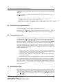
The file tree of the complete distribution is presented in Figure 9. At the top a README
and a RELEASENOTE file briefly describe this library and how to use it. The LICENSE file
describes the licensing and contractual issues of the TLM POWER library. The ‘src’ and
the ‘include’ directories contain the source code of the library. The static library version is
located in the ‘lib’ directory. The simple TAC platform presented at §8 is located in the ‘examples’ directory. This directory also contains an example of a simple platform composed
of a producer and a consumer exchanging messages. This document, an overview presentation, and a ‘doxygen’ documentation of the source code can be found in the directory ‘doc’
Finally, the ‘test’ directory contains a set of non-regression tests.
11.1
Compilation Modes
The library can be compiled in verbose mode. It can also be compiled in debug/developer’s
mode. This is conrolled by setting the relevant flags in the environment or at the top of the
Makefile.def if used or else as configure options.
TLM Power 3.0 (CBG) User Manual
Version: CBG 3.2 Alpha
DRAFT MANUAL - UPDATED 1Q2015 - Rev f
28
MY Yasin, C Koch-Hofer, Pascal Vivet, DJ Greaves
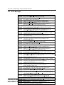
12
12.1
Messages
Warning Messages
Message:
Meaning:
Message:
Meaning:
Message:
Meaning:
Message:
Meaning:
Message:
Meaning:
Message:
Meaning:
Message:
Meaning:
Message:
Meaning:
Message:
Meaning:
Overflow with pw power data.
Arithmetic operation with power value has generated an overflow.
Underflow with pw power data.
Arithmetic operation with power value has generated an underflow.
Overflow with pw power unit data.
Try to use or to perform some operation with invalid unit of power.
Overflow with pw energy data.
Arithmetic operation with energy value has generated an overflow.
Underflow with pw energy date
Arithmetic operation with energy value has generated an underflow.
Overflow with pw energy unit data.
Try to use or to perform some operation with invalid unit of energy.
Redefinition of the power couple (XXX, XXX).
The same couple of power mode and power phase was defined more
than one time in the same configuration file.
Reach end of infinite simulation without calling SC STOP.
For properly generating the textual trace file, the SystemC
function SC STOP shall be called at the end of the simulation.
Reach end of infinite simulation with non null power value (XXX).
At the end of infinite simulation the module XXX has non-null power
value. For preserving coherency, the power consumption of this module
will be calculated until the last power modification of the System.
TLM Power 3.0 (CBG) User Manual
Version: CBG 3.2 Alpha
DRAFT MANUAL - UPDATED 1Q2015 - Rev f
29
MY Yasin, C Koch-Hofer, Pascal Vivet, DJ Greaves
TLM Power 3.0 (CBG) User Manual
Version: CBG 3.2 Alpha
DRAFT MANUAL - UPDATED 1Q2015 - Rev f
30
MY Yasin, C Koch-Hofer, Pascal Vivet, DJ Greaves
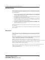
12.2
Error Messages
Message:
Meaning:
Message:
Meaning:
Message:
Meaning:
Message:
Meaning:
Message:
Meaning:
Message:
Meaning:
Message:
Meaning:
Message:
Meaning:
Message:
Meaning:
Message:
Meaning:
Message:
Meaning:
Message:
Meaning:
Message:
Meaning:
Message:
Meaning:
Message:
Meaning:
Message:
Meaning:
Message:
Meaning:
Overflow with pw power unit data.
Try to create a power value with an incorrect unit.
Division by zero not allowed with pw power.
Try to divide a power value with zero.
Power resolution can only be set during elaboration phase.
Call the SET POWER resolution during the simulation phase.
Power resolution already fixed.
Call the SET POWER resolution function more than one time or
after constructing a power object different from zero.
Power value must be positive.
Try to construct a power object with a negative double parameter.
Overflow with power resolution value.
The SET POWER resolution function was called with an incorrect
double parameter (greater than 264 -1 or fewer than 1.0).
Failed to initialize input stream.
The initialization of an input stream (POWER UNIT, power, ...) failed.
Failed to extract power value from input stream.
The token of an input stream was not representing a power
value (syntax error).
Failed to extract power value from input stream
The token of an input stream was not representing a power
unit value (syntax error).
Overflow with pw energy unit data.
Try to create an energy value with an incorrect unit.
Division by zero not allowed with pw energy.
Try to divide an energy value with zero.
Energy resolution can only be set during elaboration phase.
Call the SET ENERGY resolution during the simulation phase.
Energy resolution already fixed.
Call the SET ENERGY resolution function more than one time or
after constructing a energy object different from zero.
Energy value must be positive.
Try to construct a energy object with a negative double parameter.
Overflow with energy resolution value.
The SET ENERGY resolution function was called with an incorrect double
parameter (greater than 264 -1 or fewer than 1.0).
Failed to initialize input stream.
The initialization of an input stream (ENERGY UNIT, energy, ...) failed.
Failed to extract energy value from input stream.
The token of an input stream was not representing an
energy value (syntax error).
Message: Failed to extract energy value from input stream
Meaning: The token of an input stream was not representing an
energy unit value (syntax error).
Message: Division by zero not allowed.
Meaning: Try to divide an energy value with a zero power or time value.
Message: Overflow with pw module base::ATTRIBUTE ID data.
Meaning: Internal error code which should not happen.
Message: Power module must be an SC OBJECT.
Meaning: Try to use the pw module or the pw module base class with an object
not inheriting of the class SC OBJECT.
Message: Unknown power mode: failed to switch from (XXX, XXX) to (XXX, XXX).
Meaning: Call the UPDATE POWER method of the class pw module with
power and/or phase parameter not defined in the configuration file.
Message: Failed to initialize output stream.
Meaning: The initialization of an output stream (ENERGY UNIT, energy, ...) failed.
TLM Power 3.0 (CBG)Message:
User Manual
31
Failed to open configuration file XXX (YYY).
Meaning: Unable to open the configuration file XXX for the reason YYY.
Version: CBG 3.2 Alpha
Message: 1Q2015
No power
value
DRAFT MANUAL - UPDATED
- Rev
f associated to the couple (XXX, XXX).
Meaning: Internal error code which should not happen.
MY Yasin, C Koch-Hofer, Pascal Vivet, DJ Greaves
Revision History
Version 1 this library was developed, by Hugo Lebreton, for evaluating the power management mechanisms designed for the Magali Platform [2]. This first version was suffering from
the following limitations:
1. The power and energy value are defined by raw value which can lead to un-debuggable
errors: for example mixing raw values using different implicit units (e.g. milli-watt and
pico-watt) or types (e.g. power and energy).
2. The designer has to define intermediary classes and enumerated types for accessing
and setting the power values of a SystemC module.
3. The statistic module does not take into account the mode and phase. For example, it
was the responsibility of the user intermediary classes to compute the global energy
consumed by a module for different mode and phase.
4. The power consumption of a module does not care about the consumption of its
sub-module. It was not possible to automatically generate power information on the
module CLUSTER0 from its sub-module.
Version 2.0 of this library was developed by C Koch-Hofer, Pascal Vivet at CEA to overcome
these problems.
Version 3.0 (CBG) shifted the focus to energy-based modelling of transactions and added
physical distances.
References
[1]H. Lebreton and P. Vivet: Power Modeling in SystemC at Transaction Level, Application
to a DVFS Architecture. IVLSI’08: International Symposium on VLSI, Montpellier, FR, 2008,
pp. 463-466.
[2]H. Lebreton: ModC)lisation de la consommation C)lectrique en SystemC/TLM et rC)duction
de la consummation par le contrC4le de mC)canisme DVFS. DiplC4me de recherche technologique, Institut National Polytechnique de Grenoble (INPG), 2009.
[3]IEEE Std. 1666-2005: IEEE: Standard SystemC Language Reference Manual. NY, USA,
2006, ISBN 0-7381-4871-7. http://standards.ieee.org/getieee/1666/index.htmlhttp://standards.ieee.org/getieee
[4]IEC Std 61691-4:2004, IEEE Std 1364-2001: Behavioural languages — Part 4: VerilogB.
hardware description language. 2004, pp. 349-374.
[5]File Formats that are supported in Excel. http://office.microsoft.com/en-us/excel/HP100141031033.aspx
TODO: mention PlotCombinedAccounts for VCD tracing. mention title mention CSV output
? mention .plt variation on vcd
TLM Power 3.0 (CBG) User Manual
Version: CBG 3.2 Alpha
DRAFT MANUAL - UPDATED 1Q2015 - Rev f
32