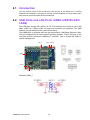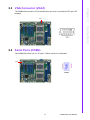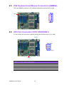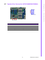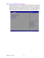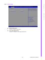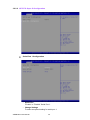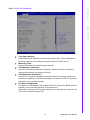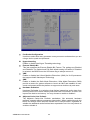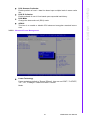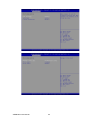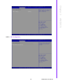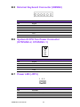
1
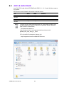
User Manual ASMB-823I Dual LGA 2011-R3 Intel Xeon® E5-2600v3 ATX Server Board Copyright The documentation and the software included with this product are copyrighted 2014 by Advantech Co., Ltd. All rights are reserved. Advantech Co., Ltd. reserves the right to make improvements in the products described in this manual at any time without notice. No part of this manual may be reproduced, copied, translated or transmitted in any form or by any means without the prior written permission of Advantech Co., Ltd. Information provided in this manual is intended to be accurate and reliable. However, Advantech Co., Ltd. assumes no responsibility for its use, nor for any infringements of the rights of third parties, which may result from its use. Acknowledgements Intel and Pentium are trademarks of Intel® Corporation. Microsoft Windows and MS-DOS are registered trademarks of Microsoft® Corp. All other product names or trademarks are properties of their respective owners. Product Warranty (2 years) Advantech warrants to you, the original purchaser, that each of its products will be free from defects in materials and workmanship for two years from the date of purchase. This warranty does not apply to any products which have been repaired or altered by persons other than repair personnel authorized by Advantech, or which have been subject to misuse, abuse, accident or improper installation. Advantech assumes no liability under the terms of this warranty as a consequence of such events. Because of Advantech’s high quality-control standards and rigorous testing, most of our customers never need to use our repair service. If an Advantech product is defective, it will be repaired or replaced at no charge during the warranty period. For outof-warranty repairs, you will be billed according to the cost of replacement materials, service time and freight. Please consult your dealer for more details. If you think you have a defective product, follow these steps: 1. Collect all the information about the problem encountered. (For example, CPU speed, Advantech products used, other hardware and software used, etc.) Note anything abnormal and list any onscreen messages you get when the problem occurs. 2. Call your dealer and describe the problem. Please have your manual, product, and any helpful information readily available. 3. If your product is diagnosed as defective, obtain an RMA (return merchandise authorization) number from your dealer. This allows us to process your return more quickly. 4. Carefully pack the defective product, a fully-completed Repair and Replacement Order Card and a photocopy proof of purchase date (such as your sales receipt) in a shippable container. A product returned without proof of the purchase date is not eligible for warranty service. 5. Write the RMA number visibly on the outside of the package and ship it prepaid to your dealer. ASMB-823I User Manual Part No. 2006823I10 Edition 1 Printed in Taiwan November 2014 ii A Message to the Customer Advantech Customer Services Each and every Advantech product is built to the most exacting specifications to ensure reliable performance in the harsh and demanding conditions typical of industrial environments. Whether your new Advantech equipment is destined for the laboratory or the factory floor, you can be assured that your product will provide the reliability and ease of operation for which the name Advantech has come to be known. Your satisfaction is our primary concern. Here is a guide to Advantech’s customer services. To ensure you get the full benefit of our services, please follow the instructions below carefully. Technical Support We want you to get the maximum performance from your products. So if you run into technical difficulties, we are here to help. For the most frequently asked questions, you can easily find answers in your product documentation. These answers are normally a lot more detailed than the ones we can give over the phone. So please consult this manual first. If you still cannot find the answer, gather all the information or questions that apply to your problem, and with the product close at hand, call your dealer. Our dealers are well trained and ready to give you the support you need to get the most from your Advantech products. In fact, most problems reported are minor and are easily solved over the phone. In addition, free technical support is available from Advantech engineers every business day. We are always ready to give advice on application requirements or specific information on the installation and operation of any of our products. iii ASMB-823I User Manual Declaration of Conformity FCC Class B Note: This equipment has been tested and found to comply with the limits for a Class B digital device, pursuant to part 15 of the FCC Rules. These limits are designed to provide reasonable protection against harmful interference in a residential installation. This equipment generates, uses and can radiate radio frequency energy and, if not installed and used in accordance with the instructions, may cause harmful interference to radio communications. However, there is no guarantee that interference will not occur in a particular installation. If this equipment does cause harmful interference to radio or television reception, which can be determined by turning the equipment off and on, the user is encouraged to try to correct the interference by one or more of the following measures: Reorient or relocate the receiving antenna. Increase the separation between the equipment and receiver. Connect the equipment into an outlet on a circuit different from that to which the receiver is connected. Consult the dealer or an experienced radio/TV technician for help. Caution! There is a danger of a new battery exploding if it is incorrectly installed. Do not attempt to recharge, force open, or heat the battery. Replace the battery only with the same or equivalent type recommended by the manufacturer. Discard used batteries according to the manufacturer's instructions. ASMB-823I User Manual iv Peripheral Compatibility Category Advantech PN MB Vendor Part Description ASMB-823I-00A1E Advantech Support BMC module ASMB-823-00A1E Advantech Basic sku Intel E5-2600 v3 product family (DQA QVL CPUs) CPU SATA HDD 2.5" & 3.5" SATA2 & SATA3 HDD device (DQA QVL HDDs) Memory DDR4 ECC-REG 2133/1866/1600 MHz DIMM (DQA QVL DIMM modules) Cooler/ Heatsink Option Card Riser Card Remarks 1960055362N001 AVC LGA-2011 square CPU cooler for 2U/ 4U chassis (145 W) 1960065684N001 Coolermaster LGA-2011 square CPU cooler for 4U chassis (160 W) PCA-AUDIOHDA1E Advantech Audio card ASMB-RF34821A1E Advantech ASMB-RF348 (2U riser card) 2*PCI-E x4 + 1*PCI-E x8 ASMB-RF3X821A1E Advantech ASMB-RF3X8 (2U riser card) 1*PCI-Ex4 + 2*PCI-X v ASMB-823I User Manual Initial Inspection Before installing motherboard, please make sure that the following materials have been shipped: 1 x ASMB-823I ATX motherboard 1 x ASMB-823I Startup Manual 1 x Driver CD (user manual is included) 2 x Serial ATA HDD data cables 1 x I/O port bracket 2 x CPU power cable (8P) 2 x SATA power cable 1 x Warranty card If any of these items are missing or damaged, contact distributor or sales representative immediately. We have carefully inspected the ASMB-823I mechanically and electrically before shipment. It should be free of marks and scratches and in perfect working order upon receipt. When unpacking the ASMB-823I, check it for signs of shipping damage. (For example, damaged box, scratches, dents, etc.) If it is damaged or it fails to meet the specifications, notify our service department or local sales representative immediately. Also notify the carrier. Retain the shipping carton and packing material for inspection by the carrier. After inspection, we will make arrangements to repair or replace the unit. Order Information Part Number HDD Expansion Slot IPMI ASMB-823I-00A1E 9*SATA3 4 PCIe x16 + 2 PCIe x8 (Gen 3.0) + PCIe x4 (Gen 2.0) Yes ASMB-823-00A1E 9*SATA3 4 PCIe x16 + 2 PCIe x8 (Gen 3.0) + PCIe x4 (Gen 2.0) - ASMB-823I User Manual vi Contents Chapter 1 Overview...............................................1 1.1 1.2 1.3 1.6 1.7 1.8 Introduction ............................................................................................... 2 Features .................................................................................................... 2 Specifications ............................................................................................ 3 Table 1.1: Specifications ............................................................. 3 Board Layout, Jumpers and Connectors................................................... 5 Figure 1.1 Board Layout .............................................................. 5 Figure 1.2 Rear I/O ...................................................................... 5 Table 1.2: Onboard LAN LED Color Definition ............................ 6 Table 1.3: Jumpers...................................................................... 6 Table 1.4: Connectors ................................................................. 6 Table 1.5: Onboard LED.............................................................. 7 Block Diagram........................................................................................... 8 Figure 1.3 Block Diagram ............................................................ 8 System Memory ........................................................................................ 8 Memory Installation Procedures................................................................ 8 Processor Installation.............................................................................. 11 2 Connections ......................................15 2.1 2.2 2.3 2.4 2.5 2.6 2.9 2.10 2.11 2.12 2.13 2.14 2.15 2.16 2.17 2.18 2.19 2.20 2.21 Introduction ............................................................................................. 16 USB Ports and LAN Ports (USB0~USB10/LAN1/LAN2)......................... 16 VGA Connector (VGA1) .......................................................................... 17 Serial Ports (COM2)................................................................................ 17 PS2 Keyboard and Mouse Connectors (KBMS2) ................................... 18 CPU Fan Connector (CPU FAN0/FAN1) ................................................ 18 Table 2.1: CPU FAN Pin Definition............................................ 18 System Fan Connector (SYS FAN0/FAN1/FAN2) .................................. 19 Table 2.2: SYS FAN Pin Definition ............................................ 19 Front Panel Connector (JFP1) ................................................................ 20 2.8.1 Power LED (JFP3) ...................................................................... 20 Table 2.3: ATX Power Supply LED Status ................................ 20 2.8.2 External Speaker (JFP2 pins 1, 4, 7, 10) .................................... 20 2.8.3 HDD LED Connector (JFP1 Pins 2 & 5) ..................................... 21 2.8.4 Reset Connector (JFP1 Pins 9 & 12).......................................... 21 2.8.5 SNMP Connector (JFP1 Pins 8 & 11)......................................... 21 2.8.6 Case Open (JCASE1)................................................................. 21 SATA SGPIO (SGPIO1 & 2) ................................................................... 22 Front Panel LAN Indicator Connector (LANLED1).................................. 23 Serial ATA Interface (SATA0-SATA4, sSATA0-sSATA3) ....................... 24 PCIe & PCI Expansion Slots ................................................................... 25 Auxiliary Power Connector (ATXPWR1/ATX12V1/ATX12V2) ................ 26 HD Audio Interface Connector (HDAUD1) .............................................. 27 LPC Connector (LPC1) for Optional TPM Module .................................. 28 Clear CMOS Connector (JCMOS1, JME1) ............................................. 29 PMBUS Connector (PMBUS1)................................................................ 30 Front Panel SMBUS Connector (SMBUS1) ............................................ 31 IPMI Module Connector (BMC1) ............................................................. 31 VOLT1 Connector (VOLT1) .................................................................... 32 GPIO Connector (GPIO1) ....................................................................... 33 3 AMI BIOS ............................................35 1.4 1.5 Chapter 2.7 2.8 Chapter vii ASMB-823I User Manual 3.1 3.2 Introduction ............................................................................................. 36 BIOS Setup ............................................................................................. 37 3.2.1 Main Menu .................................................................................. 37 3.2.2 Advanced BIOS Features Setup................................................. 38 3.2.3 IntelRCSetup .............................................................................. 49 3.2.4 Server Management ................................................................... 66 3.2.5 Security....................................................................................... 67 3.2.6 Boot ............................................................................................ 68 3.2.7 Save & Exit ................................................................................. 69 4 Chipset Software Installation Utility 71 4.1 4.2 4.3 Before Beginning .................................................................................... 72 Introduction ............................................................................................. 72 4.2.1 Main Menu .................................................................................. 72 Windows 7 & 8/ Windows server 2008 & 2012 ....................................... 73 5 VGA Setup ......................................... 75 5.1 5.2 Introduction ............................................................................................. 76 Windows Series Driver Setup ................................................................. 76 6 LAN Configuration & USB 3.0.......... 79 6.1 6.3 LAN Configuration................................................................................... 80 6.1.1 Introduction ................................................................................. 80 6.1.2 Features...................................................................................... 80 6.1.3 Installation................................................................................... 80 6.1.4 Windows Series Driver Setup (LAN)........................................... 80 USB 3.0................................................................................................... 81 6.2.1 Introduction ................................................................................. 81 6.2.2 Windows Series Driver Setup ..................................................... 81 AHCI & SATA RAID ................................................................................ 82 Appendix A Programming the Watchdog Timer . 83 A.1 A.2 Watchdog Timer Overview...................................................................... 84 Programming the Watchdog Timer ......................................................... 84 Table A.1: Watchdog Timer Registers....................................... 86 A.2.1 Example Programs ..................................................................... 86 Appendix B I/O Pin Assignments ......................... 91 B.1 USB2.0 Header (USB67/89) ................................................................... 92 Table B.1: USB Header (USB67) .............................................. 92 USB3.0 Header(USB2_3) ....................................................................... 92 Table B.2: USB Header (USB23,USB45,USB67,USB89) ......... 92 VGA Connector (VGA1).......................................................................... 93 Table B.3: VGA Connector (VGA1) ........................................... 93 RS-232 Interface (COM2) ....................................................................... 93 Table B.4: RS-232 Interface (COM2) ........................................ 93 External Keyboard Connector (KBMS2) ................................................. 94 Table B.5: External Keyboard Connector (KBMS2)................... 94 System & CPU Fan Power Connector (SYSFAN0~2, CPUFAN0~1) ..... 94 Table B.6: Fan Power Connector (SYSFAN0~2, CPUFAN0~1) 94 Power LED (JFP3) .................................................................................. 94 Chapter Chapter Chapter 6.2 B.2 B.3 B.4 B.5 B.6 B.7 ASMB-823I User Manual viii B.8 B.9 B.10 B.11 B.12 B.13 B.14 B.15 B.16 B.17 Table B.7: Power LED (JFP1).................................................... 94 External Speaker Connector (JFP2) ....................................................... 95 Table B.8: External Speaker Connector (JFP2)......................... 95 Reset Connector (JFP1) ......................................................................... 95 Table B.9: Reset Connector (JFP1)........................................... 95 HDD LED Connector (JFP1) ................................................................... 95 Table B.10:HDD LED Connector (JFP1) .................................... 95 ATX Soft Power Switch (JFP1) ............................................................... 96 Table B.11:ATX Soft Power Switch (JFP1)................................. 96 Front panel SMBus Connector (SMBUS1).............................................. 96 USB/LAN Ports (USB0_1, USB4_5 and LAN1_2) .................................. 97 Table B.12:USB Port................................................................... 97 Table B.13:Giga LAN 10/100/1000 Base-T RJ-45 Port .............. 97 Audio Connector (HDAUD1) ................................................................... 97 Table B.14:Front Panel Audio Connector (HDAUD1) ................. 97 8-pin Alarm Board Connector (VOLT1)................................................... 98 Table B.15:8-pin Alarm Board Connector (VOLT1) .................... 98 Case Open Connector (JCASE1) ........................................................... 98 Table B.16:Case Open Connector (JFP1) .................................. 98 Front Panel LAN LED Connector (LANLED1)......................................... 98 Table B.17:LAN LED Connector (LANLED1).............................. 98 ix ASMB-823I User Manual ASMB-823I User Manual x Chapter 1 Overview 1 1.1 Introduction The ASMB-823I serverboard is the most advanced Intel Xeon E5-2600 (V3) series board for server-grade IPC applications that require high-performance computing power & multi-expansion slots. This serverboard supports Intel Xeon E5-2600 (V3) series processor and DDR4 2133/1866/1600 MHz memory up to 192 GB. ASMB-823I provides four PCIe x16 slots (Gen3) + two PCIe x8 slots (Gen3.0) and one PCie x4 (Gen2.0). In addition, the ASMB-823I has dual Gigabit Ethernet LAN ports via a dedicated PCIe x1 bus, which offer bandwidth up to 500 MB/s, eliminating network bottlenecks. One RJ-45 LAN jack is shared with IPMI function that allows remote control management. High reliability and outstanding performance makes ASMB-823I the ideal platform for industrial server/networking applications. By using the Intel C612 chipset, the ASMB-823I offers a variety of features such as 9 onboard SATA III interfaces; it supports IRST (Intel Rapid Storage Technology) and provides RAID 0, 1, 10 and 5 (Windows only*); and it has 6 USB 3.0 and 3 USB 2.0 connectors. These powerful I/O capabilities ensure even more reliable data storage capabilities and high-speed I/O peripheral connectivity. Note! 1. 2. 3. IPMI module will be included in ASMB-823I sku. Three USB 2.0 ports (1*Type- A) and six USB 3.0 ports (2 ports from on-board 20-pin header) Please refer to the release note of each Linux OS for Intel's C612 chipset SATA RAID function support. 1.2 Features General Intel E5-2600 (v3) processor support: ASMB-823I supports two Intel E5-2600 (v3) series six/eight/ten/twelve/fourteen/sixteen/eighteen core processors. High performance I/O capability: Dual Gigabit LAN, 4 x PCIe x16 slot (x16 link) + 2 x PCIe x16 slot (x8 link) + 1x PCIe x8 slot (x4 link), 9 x SATA connectors and 6 x USB 3.0, 3 x USB 2.0. Standard EATX form factor with industrial features: ASMB-823I provides industrial features like long product lifecycle, reliable operation under wide temperature range, watchdog timer, etc. IPMI 2.0 support: ASMB-823I equipped with ASPEED 2400 BMC chip supports IPMI 2.0 (Intelligent Platform Management Interface 2.0) via sharing LAN port. KVM over IP: ASMB-823I KVM over IP function allows remote control of system through your own computer. ASMB-823I User Manual 2 Table 1.1: Specifications Processor Memory Capacity Xeon processor supports DDR4 memory bus Total 6 memory slots provided Supports up to 192 GB memory Quad channels per processor, 2 memory slot per channel Memory Type Supports DDR4 2133/1866/1600/1333 MHz ECC-REG Modules DIMM Sizes Each memory slot supports 1GB, 2GB, 4GB, 8GB, 16GB and 32GB memory modules Memory Voltage 1.2 V Error Detection CPU System Memory Corrects single-bit errors Detects double-bit errors (using ECC memory) On-Board Devices Chipsets Intel C612 PCH provide 8xPCIe Gen2 lanes Network Controllers 2 x Intel I210 Gigabit Ethernet Controller connected to C612 through PCIe x1 Gen2 Lane Above network supports 10BASE-T, 100BASE-TX, and 1000BASE-T, with RJ-45 output VGA ASPEED AST2400/1400 controller with 64 MB VGA memory provides basic 2D VGA function. Super I/O Nuvoton NCT6776D chip provide motherboard keyboard mouse, RS-232, parallel port and hardware monitor functions BMC (823I SKU Only) One of Intel I210 Gigabit Ethernet connected to AST2400 for sharing IPMI / IKVM Input / Output Serial ATA Total 9 x SATA ports and provide 6 Gb/s bandwidth RAID 0, 1, 5, 10 support (Windows only. For Linux support please refer to the note item 3 of chapter 1.1) LAN 2 x RJ-45 LAN ports (10/100/1000 Base-T LAN) USB 4 x USB 3.0 ports at rear window 1 x USB 2.0 internal headers (2 ports) 1 x USB 3.0 internal header (2 ports) 1 x internal Type-A USB port. VGA 1 x VGA port. Keyboard / Mouse PS/2 keyboard and mouse connector (onboard). Serial Port / Header 1 x internal header (2 x 5P pitch: 2.50 mm) for UART port. Power Connector System Power 1 x 24-pin SSI EPS 12 V power connector (Input 12 V, 5 V, 3.3 V, 5 V standby) CPU Power 2 x 8 pin SSI EPS 12 V power connector for CPU & Memory power (12V) PCIe slot power 1 x 4pin 12 V power connector for PCIe slot 12 V input 3 ASMB-823I User Manual Overview Dual Intel LGA2011 Xeon processor sockets Supports Intel Xeon E5-2600 (v3) series processor with six/ eight/ten/twelve/fourteen/sixteen/eighteen cores Supports the TDP of processor up to 160 W Chapter 1 1.3 Specifications Table 1.1: Specifications Expansion Slots PCI-express 4 x PCIe x16 slot (Gen3 x16 link) – PCIEX16_SLOT2 (from CPU 1) – PCIEX16_SLOT4 (from CPU 0) – PCIEX16_SLOT5 (from CPU 1) – PCIEX16_SLOT6 (from CPU 0) 2 x PCIe x8 slot (Gen3 x8 link) – PCIEX16_SLOT3 (from CPU 1) – PCIEX16_SLOT7 (from CPU 0) 1 x PCIe x8 slot (Gen2 x4 link) – PCIEX8_SLOT1 (from PCH) System BIOS BIOS Type 128 Mb SPI Flash EEPROM with AMI BIOS PC Health Monitoring Voltage Monitors for CPU Cores, +3.3 V, +5 V, +12 V, +5 V Standby, VBAT Two 4-pin heads for CPU cooler and three 4-pin headers for system fan All fans with tachometer status monitoring Thermal control for all fan connectors Temperature Monitoring for CPU (PECI) Monitoring for System (SIO) Other Features (Case Open) Chassis intrusion detection Chassis intrusion header FAN Operating Environment / Compliance RoHS Environmental Spec. ASMB-823I User Manual RoHS Compliant 6/6 Pb Free Operating Temperature: 0 to 40° C Non-operating Temperature: -40 to 85° C Operating Relative Humidity: 10% to 90% (non-condensing) Non-operating Relative Humidity: 10% to 95% (non-condensing) 4 Connectors on the ASMB-823I are linked to external devices such as hard disk drives. In addition, ASMB-823I has a number of jumpers that are used to configure the system for specific applications. The tables below list the functions of each jumper and connector. Later sections in this chapter give instructions for setting jumpers. Chapter 2 gives instructions for connecting external devices to ASMB-823I. BMC1 LAN1_2 BMC2 USB0_1 USB4_5 CPU FAN1 KBMS2 COM2 ATX12V2 DIMM H1 HDAUD 1 PCIEx8_SLOT1 PCIEx16_SLOT2 DIMM G2 USB10 DIMM G1 PCIEx8_SLOT3 PCIEx16_SLOT4 PCIEx16_SLOT5 PCIEx16_SLOT6 PCIEx8_SLOT7 sSATA0, 2, 3 CPU1 PMBUS1 SATA0-4 SYS_LED1 PCH CPU0 LPC1 USB6_7 JFP1 JFP2 JPF3 JCASE1 ATXPWR1 DIMMA1 DIMMA2 DIMMB1 JTHR_SEL1 & JME1 LANLED1 JCMOS1 SMBUS1 VOLT1 SGPIO1 & 2 SYS FAN2 SYS FAN0 GPIO1 SYS FAN1 CPU SLOT12V1 FAN0 ATX12V1 sSATA1 BIOS1 SP1_CN1 USB2_3 EX_THR1 Figure 1.1 Board Layout LAN1 ASMB-823I-00A1E ASMB-823-00A1E USB4_5 USB0_1 VGA1 LAN2 (sharing LAN for BMC) Figure 1.2 Rear I/O 5 ASMB-823I User Manual Overview VGA1 Chapter 1 1.4 Board Layout, Jumpers and Connectors Table 1.2: Onboard LAN LED Color Definition 10/100/1000 Mbps LAN Link/Activity LED Scheme LAN1 & LAN2 Left LED Right LED 10 Mbps Link Active Off Off Green Blinking green 100 Mbps Link Active Amber Amber Green Blinking green 1000 Mbps Link Active Green Green Green Blinking green Off Off No Link Table 1.3: Jumpers Label Function Default JCMOS1 CMOS Clear 1-2 JME1 ME update 1-2 1 2 1 3 Keep CMOS data/ Disable ME update/ 2 3 Clear CMOS data/ Enable ME update/ Table 1.4: Connectors Label Function ATX12V1 SSI EPS 12V auxiliary power connector (for CPU0) and memory ATX12V2 SSI EPS 12V auxiliary power connector (for CPU1) and memory ATXPWR1 SSI EPS 24-pin main power connector (for system) AUDIO1 HD audio Interface connector BIOS1 BIOS SPI ROM BMC1, BMC2 IPMI connector COM2 Serial port: RS-232 CPU0 Intel LGA2011 CPU0 socket CPU1 Intel LGA2011 CPU1 socket CPUFAN0 CPU0 fan connector (4-pin) CPUFAN1 CPU1 fan connector (4-pin) DIMMA1 Channel A DIMM1 of CPU0 DIMMA2 Channel A DIMM2 of CPU0 DIMMB1 Channel B DIMM1 of CPU0 DIMMG1 Channel G DIMM1 of CPU1 ASMB-823I User Manual 6 Chapter 1 Table 1.4: Connectors Channel G DIMM2 of CPU1 DIMMH1 Channel H DIMM1 of CPU1 EX_THR1 Connector for external thermistor GPIO1 GPIO function for customize usage HDAUD1 Audio header JCASE1 Chassis case open alarm header JFP1/JFP2/JFP3 Front panel pin header connector KBMS2 For additional keyboard/mouse LAN1, LAN2 RJ-45 LAN connector LANLED1 LAN1 & LAN2 LED extension connector LPC1 LPC port for debug & TPM module PMBUS1 Power supply SMBbus I2C Header SATA0~SATA4, sSATA0~sSATA3 Serial ATA0~4, Slave serial ATA0~3 SGPIO1, SGPIO2 Supports Serial_Link interface for onboard SATA connections SLOT1 PCIE x8 slot (x4 link) of PCH SLOT2 PCIE x16 slot of CPU1 SLOT3 PCIE x8 slot of CPU1 SLOT4 PCIE x16 slot of CPU0 SLOT5 PCIE x16 slot of CPU1 SLOT6 PCIE x16 slot of CPU0 Overview DIMMG2 SLOT7 PCIE x8 slot of CPU0 SLOT12V1 For PCIe slot 12V input only SMBUS1 SMBus header (For Advantech chassis usage) SPI_CN1 Connector for BIOS update tool SYS FAN0 System fan connector (4-pin) SYS FAN1 System fan connector (4-pin) SYS FAN2 System fan connector (4-pin) SYS_LED1 System LED connector USB0_1, USB2_3, USB4_5 USB 3.0 port 0, 1, 4, 5; USB 3.0 port 2, 3 (20pin header) USB67 USB 2.0 port 6, 7 USB10 USB 2.0 port 10 (Type-A) VGA1 VGA connector VOLT1 For Advantech alarm board usage Table 1.5: Onboard LED LED Description LED Definition 5V_LED1 Power on LED Off: Power off On (Green): System is On Off: No input AC Power On (Green): System is ON, in sleep mode, or in soft-off mode 5VSB_LED1 Standby LED LED3 BMC heartbeat LED Blinking (Green): (ASMB-823I SKU Only) Controller is working normally 7 ASMB-823I User Manual 1.5 Block Diagram DDR4 1333/1600/1866/2133 DDR4 1333/1600/1866/2133 Channel A Channel G DDR4 1333/1600/1866/2133 DDR4 1333/1600/1866/2133 QPI Port0: 9.6GT/s DDR4 1333/1600/1866/2133 Channel H Slot 2 PCIe x8 Slot Slot 3 PCIe x16 Slot Slot 5 Intel LGA2011-R3 Xeon E5-2600 V3 Series Processor (CPU0) DDR4 1333/1600/1866/2133 Channel B PCIe Gen3 x16 PCIe x16 Slot Slot 4 PCIe Gen3 x8 PCIe Gen3 x16 PCIe x16 Slot Slot 6 PCIe Gen3 x16 PCIe Gen3 x8 PCIe x8 Slot Slot 7 PCIe Gen3 x16 QPI Port1: 9.6GT/s DMI Gen2 x4 PCIe x16 Slot Intel LGA2011-R3 Xeon E5-2600 V3 Series Processor (CPU1) Slot 1 5 x SATA3 (RAID 0,1,510) 4 x SATA3 3 x USB 2.0 (1 type A) (2 on board from header) PCIe Gen2 x4 SATA3 6 Gb/s sSATA 6 Gb/s PCIe Gen2 x1 I210AT MDI PCIe Gen2 x1 I210AT MDI Intel C612 PCH USB 2.0 USB 2.0 PCIe Gen2 x1 AST2400 DRAM SPI SPI Flash 32MB RGB VGA Conn. USB 3.0 SPI BIOS 128Mbit RJ45 10/100/1G DDR3 HD Audio SPI BUS HD Conn. LPC BUS 6 x USB 3.0 (2 on board / 4 Rear) RJ45 10/100/1G NC-SI PCIe x8 Slot LPC Conn. LPC BUS 5 x FAN Conn. Super I/O Nuvoton NCT6776D 1 * RS-232 Header 8 bit GPIO Pin Header PS/2 KB, MS Header Figure 1.3 Block Diagram 1.6 System Memory ASMB-823I has six 288-pin memory slots for DDR4 1600/1866/2133 MHz memory modules with maximum capacity of 192 GB (Maximum 32 GB for each DIMM). ASMB-823I supports registered DIMMs memory module. 1.7 Memory Installation Procedures Single CPU Installed (CPU0) DIMM A1 1 2 3 2 3 4 5 6 V V V V V V V V V V V V V V V V V V AIMM A2 DIMM B1 Dual CPU Installed (CPU0 & CPU1) V V V DIMM G1 V DIMM G2 V DIMM H1 ASMB-823I User Manual V 8 V V Quantity of memory installed Chapter 1 Step 1 To install DIMMs, first make sure the two handles of the DIMM socket are in the “open” position. i.e. The handles lean outward. Overview Step 2 Slowly slide the DIMM module along the plastic guides on both ends of the socket, 9 ASMB-823I User Manual Step 3 Press the DIMM module right down into the socket, until you hear a click. This is when the two handles have automatically locked the memory module into the correct position of the DIMM socket. Step 4 Finished. ASMB-823I User Manual 10 The ASMB-823I is designed for Intel E5-2600 v3 series Xeon processor. Step 1 Press the first lever and move it sideways slightly until it is released from the retention tab. Chapter 1 1.8 Processor Installation Overview Step 2 Press the other lever and move it sideways slightly until it is also released from the retention tab. 11 ASMB-823I User Manual Step 3 Lift the load plate. Step 4 Position the CPU over the socket ensuring that the triangle mark on the CPU lines up with the triangle mark on the motherboard. CPU Triangle mark Step 5 Remove protective plastic cover. ASMB-823I User Manual 12 Chapter 1 Step 6 Close the load plate over the CPU. Step 8 Finished. 13 ASMB-823I User Manual Overview Step 7 Push down both levers and insert them under the retention tabs ensuring the edge of the load plate is fixed securely by both levers. ASMB-823I User Manual 14 Chapter 2 Connections 2 2.1 Introduction You can access most of the connectors from the top of the board as it is being installed in the chassis. If you have a number of cards installed, you may need to partially remove a card to make all the connections. 2.2 USB Ports and LAN Ports (USB0~USB10/LAN1/ LAN2) The USB ports comply with USB 2.0 & 3.0. Transmission rates could be up to 480 Mbps (USB 2.0) / 5Gbps (USB 3.0) and fuse protection are supported. The USB interface can be disabled in the system BIOS setup. The ASMB-823I is equipped with two high-performance 1000 Mbps Ethernet LANs. They are supported by all major network operating systems. The RJ-45 jacks on the rear plate provide convenient 1000Base-T operation. One is shared with IPMI for system management. LAN1_2 USB0_1 USB4_5 USB10 USB6_7 USB2_3 Example: USB6_7 6_7 ASMB-823I User Manual 16 The ASMB-823I includes a VGA interface that can drive conventional CRT and LCD displays. VGA1 Chapter 2 2.3 VGA Connector (VGA1) Connections 2.4 Serial Ports (COM2) The ASMB-823I offers one 2 x 5P pitch: 2.50mm serial port. (Onboard) COM2 COM2 17 ASMB-823I User Manual 2.5 PS2 Keyboard and Mouse Connectors (KBMS2) The 6-pin KBMS2 connector is for additional keyboard & mouse device usage. KBMS2 KBMS2 2.6 CPU Fan Connector (CPU FAN0/FAN1) If a fan is used, this connector supports cooling fans that draw up to 1.5A (18W). CPUFAN1 CPUFAN0 Table 2.1: CPU FAN Pin Definition CPU FAN0 CPU FAN1 1 GND GND 2 +12V +12V 3 CPU0_TACH CPU1_TACH 4 CPU0_PWM CPU1_PWM ASMB-823I User Manual 18 Chapter 2 2.7 System Fan Connector (SYS FAN0/FAN1/FAN2) Connections SYS SYS SYS FAN2 FAN FAN0 Table 2.2: SYS FAN Pin Definition SYS FAN0 SYS FAN1 SYS FAN2 1 GND GND GND 2 +12V +12V +12V 3 FAN0_TACH FAN1_TACH FAN2_TACH 4 FAN0_PWM FAN1_PWM FAN2_PWM 19 ASMB-823I User Manual 2.8 Front Panel Connector (JFP1) There are several external switches and LEDs to monitor and control the ASMB-823I. JFP1 JFP2 JFP3 2.8.1 Power LED (JFP3) JFP3 pin 1 and pin 3 are for the power LED. Refer to Appendix B for detailed information on the pin assignments. If an ATX power supply is used, the system’s power LED status will be as indicated as follows. Table 2.3: ATX Power Supply LED Status ACPI Power Mode LED (ATX power) System On (S0) On System Standby (S1) Fast flashes System Hibernation(S4) Slow flashes System Off (S5) Off 1 2 3 - + 2.8.2 External Speaker (JFP2 pins 1, 4, 7, 10) JFP2 pins 1, 4, 7, 10 connect to an external speaker. The ASMB-823I provides an onboard buzzer as an alternative. To enable the buzzer, set pins 7-10 closed. 1 4 7 + ASMB-823I User Manual 20 10 - You can connect an LED to connector JFP1 to indicate when the HDD is active. + 2 5 Chapter 2 2.8.3 HDD LED Connector (JFP1 Pins 2 & 5) 2.8.4 Reset Connector (JFP1 Pins 9 & 12) 9 12 2.8.5 SNMP Connector (JFP1 Pins 8 & 11) SNMP connector could connect with “SAB-2000” remote control board to monitor ASMB-823I through the super IO chip. 8 11 (Data) (CLK) 2.8.6 Case Open (JCASE1) A Chassis Intrusion header is located at JCASE1 on the motherboard. Attach the appropriate cable from the chassis to be informed of a chassis intrusion when the chassis is opened. The default function is disabled and Pin 1-2 is bridged by a jumper cap. 1 2 JCASE1 21 ASMB-823I User Manual Connections Many computer cases offer the convenience of a reset button. 2.9 SATA SGPIO (SGPIO1 & 2) SGPIO1 & 2 1 SCLOCK_PCH 2 NC 3 SLOAD_PCH 4 SDATAOUT0_PCH 5 SDATAOUT1_PCH ASMB-823I User Manual 22 Chapter 2 2.10 Front Panel LAN Indicator Connector (LANLED1) Connections LANLED1 1 LAN1_LED0_ACT 2 LAN2_LED1_ACT 3 VCC3_LAN1LED 4 VCC3_LAN2LED 5 LAN1_LED1_1000M 6 LAN2_LED2_1000 7 LAN1_LED2_100M 8 LAN2_LED0_100 9 VCC3 10 NC 23 ASMB-823I User Manual 2.11 Serial ATA Interface (SATA0-SATA4, sSATA0sSATA3) ASMB-823I features nine serial ATA III interfaces (up to 600 MB/s) which eases cabling to hard drives with thin and long cables. The sSATA1 located next to CPU0 allows SATA DOM (Serial ATA Disk on Module) installation for special application usage. sSATA0,2,3 SATA0-3 sSATA1 ASMB-823I User Manual 24 Chapter 2 2.12 PCIe & PCI Expansion Slots The ASMB-823I provides several expansion slots. PCIEx8_SLOT7 PCIEx8_SLOT1 Connections PCIEx8_SLOT2 PCIEx8_SLOT3 PCIEx8_SLOT4 PCIEx8_SLOT5 PCIEx8_SLOT6 Slot Length Link PCI-E Generation PCIe link provide from SLOT1 PCI-E x8 PCI-E x4 2 PCH SLOT2 PCI-E x16 PCI-E x16 3 CPU1 SLOT3 PCI-E x8 PCI-E x8 3 CPU1 SLOT4 PCI-E x16 PCI-E x16 3 CPU0 SLOT5 PCI-E x16 PCI-E x16 3 CPU1 SLOT6 PCI-E x16 PCI-E x16 3 CPU0 SLOT7 PCI-E x8 PCI-E x8 3 CPU0 25 ASMB-823I User Manual 2.13 Auxiliary Power Connector (ATXPWR1/ ATX12V1/ATX12V2) ATX12V2 ATXPWR1 ATX12V1 Note! 1. 2. ASMB-823I User Manual Please use a power supply which is of SSI type; minimum output should be at least 700 W. ATXPWR1 & ATX12V1 & ATX12V2 sockets should be all connected with power supply, otherwise ASMB-823I will not boot up normally. 26 HDAUD1 HDAUD1 Connections 2 1 +5 V_AUD 3 ACZ_SYNC 4 ACZ_BITCLK 5 ACZ_SDOUT 6 ACZ_SDIN0 7 ACZ_SDIN1 8 ACZ_RST# 9 +AC_12V 10 GND 11 GND 12 NC 27 Chapter 2 2.14 HD Audio Interface Connector (HDAUD1) GND ASMB-823I User Manual 2.15 LPC Connector (LPC1) for Optional TPM Module LPC1 1 CLK_33M_TPM 2 LPC_AD1 3 PLTRST_LPC 4 LPC_AD0 5 LPC_FRAME 6 +3.3V 7 LPC_AD3 8 GND 9 LPC_AD2 10 SMB_SCL_LPC 11 SERIRQ_PCH 12 SMB_SDA_LPC 13 +5V_AUX 14 +5V ASMB-823I User Manual 28 Setting jumper from pin 1-2 to pin 2-3, then back to pin 1-2 to reset CMOS data. Chapter 2 2.16 Clear CMOS Connector (JCMOS1, JME1) Connections JCMOS1 JTHR_SEL1 & JME1 JCMOS1 JME1 1 SRTC_RST_PCH NC 2 RTC_RST_PCH HDA_SDOUT_PCH 3 GND 3.3V 29 ASMB-823I User Manual 2.17 PMBUS Connector (PMBUS1) PMBUS1 1 SMB_SCL_PM 2 SMB_SDA_PM 3 SMB_ALT_PM 4 GND 5 +3.3V ASMB-823I User Manual 30 Chapter 2 2.18 Front Panel SMBUS Connector (SMBUS1) Connections SMBUS1 1 +3.3V_AUX 2 SMB_SCL_FRU 3 SMB_SDA_FRU 4 GND 2.19 IPMI Module Connector (BMC1) BMC1 IPMI1 This connector will only fit to ASMB-BMC-00A1E and only exist in ASMB-823I sku. 31 ASMB-823I User Manual 2.20 VOLT1 Connector (VOLT1) VOLT1 VOLT1 connects to the alarm board on the Advantech chassis. These alarm boards give warnings if a power supply or fan fails, if the chassis overheats, or if the backplane malfunctions. 1 5VSB 5 +5V 2 GND 6 +3.3V 3 GND 7 -12V 4 -5V 8 +12V ASMB-823I User Manual 32 Chapter 2 2.21 GPIO Connector (GPIO1) Connections GPIO1 1 SIO_GPIO0 2 SIO_GPIO4 3 SIO_GPIO1 4 SIO_GPIO5 5 SIO_GPIO2 6 SIO_GPIO6 7 SIO_GPIO3 8 SIO_GPIO7 9 VCC_GPIO0 10 GND 33 ASMB-823I User Manual ASMB-823I User Manual 34 Chapter 3 AMI BIOS 3 3.1 Introduction With the AMI BIOS Setup program, you can modify BIOS settings and control the special features of your computer. The Setup program uses a number of menus for making changes and turning the special features on or off. This chapter describes the basic navigation of the ASMB-823I setup screens. AMI's BIOS ROM has a built-in Setup program that allows users to modify the basic system configuration. This type of information is stored in battery-backed up CMOS so it retains the Setup information when the power is turned off. Note! The BIOS setup screens shown in this chapter are for reference only, they may not exactly match what you see on your display devices. ASMB-823I User Manual 36 3.2.1 Main Menu Press <Del> during bootup to enter AMI BIOS CMOS Setup Utility; the Main Menu will appear on the screen. Use arrow keys to select among the items and press <Enter> to accept or enter the sub-menu. Chapter 3 3.2 BIOS Setup AMI BIOS The Main BIOS setup screen has two main frames. The left frame displays all the options that can be configured. Grayed-out options cannot be configured; options in blue can be. The right frame displays the key legend. Above the key legend is an area reserved for a text message. When an option is selected in the left frame, it is highlighted in white. Often a text message will accompany it. System Time / System Date Use this option to change the system time and date. Highlight System Time or System Date using the <Arrow> keys. Enter new values through the keyboard. Press the <Tab> key or the <Arrow> keys to move between fields. The date must be entered in MM/DD/YY format. The time must be entered in HH:MM:SS format. 37 ASMB-823I User Manual 3.2.2 Advanced BIOS Features Setup Select the Advanced tab from the ASMB-823I setup screen to enter the Advanced BIOS setup screen. You can select any of the items in the left frame of the screen, such as CPU configuration, to go to the sub menu for that item. You can display an Advanced BIOS Setup option by highlighting it using the <Arrow> keys. All Advanced BIOS Setup options are described in this section. The Advanced BIOS Setup screens are shown below. The sub menus are described on the following pages. ASMB-823I User Manual 38 Chapter 3 3.2.2.1 ACPI Settings AMI BIOS Enable Hibernation "Enable or disable" Hibernation. Lock Legacy Resources "Enable" or "Disable" Lock Legacy Resources. 39 ASMB-823I User Manual 3.2.2.2 NCT6776 Super IO Configuration Serial Port 1 Configuration – Serial Port "Enable" or "Disable" Serial Port 1. – Change Settings To select an optimal setting for serial port 1. ASMB-823I User Manual 40 Chapter 3 3.2.2.3 NCT6776 HW Monitor AMI BIOS Case Open Warning Enable/Disable the Chassis Intrusion monitoring function. When enabled and the case is opened, the warning message will show in POST screen. Watchdog Timer Enable and Disable the watchdog timer function. CPU Warning Temperature Set the CPU warning temperature threshold. When the system reaches the warning temperature, the speaker will beep. ACPI Shutdown Temperature Set the ACPI shutdown temperature threshold. When the system reaches the shutdown temperature, it will be automatically shut down by ACPI OS to protect the system from overheat damage. Fan Mode Configuration The default of CPU/System FAN is Smart FAN IV mode and the BIOS will automatically control the FAN speed by CPU temperature. When set to manual mode, fan duty setting can be changed; the range is from 30%~100%, default setting is 50%. 41 ASMB-823I User Manual 3.2.2.4 Serial Port Console Redirection Console Redirection To "Enable or disable" console redirection feature. ASMB-823I User Manual 42 Console Redirection Settings Chapter 3 AMI BIOS – Terminal Type Select a terminal type to be used for console redirection. Options available: VT100/VT100+/ANSI /VT-UTF8. – Bits Per Second Select the baud rate for console redirection. Options available: 9600/19200/57600/115200. – Parity A parity bit can be sent with the data bits to detect some transmission errors. Even: parity bit is 0 if the number of 1's in the data bits is even. Odd: parity bit is 0 if number of 1's the data bits is odd. Mark: parity bit is always 1. Space: Parity bit is always 0. Mark and Space Parity do not allow for error detection. Options available: None/Even/Odd/Mark/Space. – Stop Bits Stop bits indicate the end of a serial data packet. (A start bit indicates the beginning). The standard setting is 1 stop bit. Communication with slow devices may require more than 1 stop bit. Options available: 1/2. – Flow Control Flow control can prevent data loss from buffer overflow. When sending data, if the receiving buffers are full, a 'stop' signal can be sent to stop the data flow. Once the buffers are empty, a 'start' signal can be sent to re-start the flow. Hardware flow control uses two wires to send start/stop signals. Options available: None/Hardware RTS/CTS. – Recorder Mode 43 ASMB-823I User Manual When this mode enabled, only text will be send. This is to capture Terminal data. Options available: Enabled/Disabled. – Legacy OS Redirection Resolution On Legacy OS, the number of Rows and Columns supported redirection. Options available: 80x24/80X25. – Putty Keypad Select function key and keypad on putty. Console Redirection Setting – Out-of-Band Mgmt Port To select the com port user would like to set for having console redirection feature. – Terminal Type Set as "VT100", "VT100+", "VT-UTF8", or "ANSI". "VT-UTF8" is the default setting. – Bits Per Second To select serial port transmission. Speed must be matched on the other side. It can be set as "9600", "19200", "57600", or "115200". "115200" is the default setting. – Flow Control Flow control can prevent data loss from buffer overflow. It can be set as "None", "Hardware RTS/CTS", or "Software Xon/Xoff". "None" is the default setting. ASMB-823I User Manual 44 Chapter 3 3.2.2.5 PCI Subsystem Settings AMI BIOS PCI / PCI-X Latency Timer Value in units of PCI clocks for PCI device latency timer register. Above 4G Decoding Enables or disables 64-bit capability. Devices to be decoded in above 4G address space (Only if system supports 64-bit PCI decoding). Note! Some graphic or GPU cards need to enable 4G Decoding. 45 ASMB-823I User Manual 3.2.2.6 CSM Configuration CSM Support Enables or disables UEFI CSM (Compatibility Support Module) to support a legacy PC boot process. GateA20 Active This items is useful When RT code is executed above 1MB. When this it's set as "UPON RQUEST", GA20 can be disabled using BIOS services. When it's set as "Always", it does not allow disabling GA20. Option ROM Messages "Force BIOS or Keep Current" to set the display mode for Option ROM ASMB-823I User Manual 46 Chapter 3 3.2.2.7 Trusted Computing AMI BIOS Security Device Support Enables or disables BIOS support for security device. Purchase Advantech LPC TPM module to enable TPM function. P/N: PCATPM00A1E. 47 ASMB-823I User Manual 3.2.2.8 USB Configuration Legacy USB Support This is for supporting USB device under a legacy OS such as DOS. When choosing "AUTO", the system will automatically detect if any USB device is plugged into the computer and enable USB legacy mode when a USB device is plugged and disable USB legacy mode when no USB device is attached. XHCI Hand-off This is a workaround for OS without XHCI hand-off support. The XHCI ownership change should be claimed by XHCI driver. EHCI Hand-off This is a workaround for OS without EHCI hand-off support. The EHCI ownership change should be claimed by EHCI driver. USB Mass Storage Driver Support Enable/Disable USB mass storage driver support. USB Transfer Time-out Selects the USB transfer time-out value. [1,5,10,20sec] Device Reset Time-out Selects the USB device reset time-out value. [10,20,30,40 sec] Device Power-up Delay This item appears only when Device power-up delay item is set to [manual]. ASMB-823I User Manual 48 Chapter 3 3.2.3 IntelRCSetup AMI BIOS 3.2.3.1 Processor Configuration 49 ASMB-823I User Manual Per-Socket Configuration Use this to select how many processor cores you want to activate when you are using a dual or quad core processor. Hyper-threading Enable or disable Intel Hyper Threading technology. Execute Disable Bit This item specifies the Execute Disable Bit Feature. The settings are Enabled and Disabled. The Optimal and Fail-Safe default setting is Enabled. If Disabled is selected, the BIOS forces the XD feature flag to always return to 0. VMX Enable or disable Intel Virtual Machine Extensions (VMX) for IA-32 processors that support Intel® Vanderpool Technology SMX Enable or disable the Safer Mode Extensions. Safer Mode Extensions (SMX) provide a means for system software to launch an MLE and establish a measured environment within the platform to support trust decisions by end users. Hardware Prefetcher Hardware Prefetcher is a technique that fetches instructions and/or data from memory into the CPU cache memory well before the CPU needs it, so that it can improve the load-to-use latency. You may choose to enable or disable it. Adjacent Cache Line Prefetch The Adjacent Cache-Line Prefetch mechanism, like automatic hardware prefetch, operates without programmer intervention. When enabled through the BIOS, two 64-byte cache lines are fetched into a 128-byte sector, regardless of whether the additional cache line has been requested or not. You may choose to enable or disable it. ASMB-823I User Manual 50 3.2.3.2 Advanced Power Management Power Technology Power technology default is "Energy Efficient". User can set "EIST", "P-STATE", "C3", "C6", "Package C State limit" under "Custom" Mode. 51 ASMB-823I User Manual AMI BIOS DCU Streamer Prefetcher Enable prefetch of next L1 data line based upon multiple loads in same cache line. DCU IP Prefetcher Enable prefetch of next L1 line based upon sequential load history. DCU Mode Change the data cache unit (DCU) mode. AES-NI This item is to enable or disable CPU advanced encryption standard instructions. Chapter 3 ASMB-823I User Manual 52 Chapter 3 AMI BIOS 3.2.3.3 QPI Configuration 53 ASMB-823I User Manual QPI Speed Mode Select the QPI link speed as either the Fast mode or Slow Mode. QPI Frequency Select Allows for selecting the QPI Link frequency. QPI Link0p Enable/Disable QPI Link0p. QPI Link1 Enable/Disable QPI Link1. COD enable Enable/Disable Cluster on Die. Early Snoop Enable/Disable Early Snoop. ASMB-823I User Manual 54 1. Snoop Mode Configuration Cluster on Die Enable Early Snoop (ES) Home Snoop (HS) Cluster on Die (COD) Not Supported - Invalid Settings 55 Early Snoop Mode Disable Enable Auto Auto Auto Enable Disable Auto Disable Disable Auto Disable Enable Disable Enable Auto Enable Enable ASMB-823I User Manual AMI BIOS 2. Intel® recommends exposing all 3 snoop modes as BIOS options to the user due to the varying memory latency & bandwidth trade offs across SKUs for each snoop mode. a). Intel® Xeon® Processor E5-2600 v3 Product Family supports up to 3 different snoop modes (Early Snoop, Home Snoop, Cluster on Die) to maintain memory coherency across the 2 sockets. b). Choosing the optimal snoop mode setting is dependent on the workload characteristics and the SKU that is used. It is expected behavior for LCC SKUs (4-8 cores) in NUMA & Early Snoop mode to have low remote bandwidth. a). For workloads on LCC SKUs that need high local & remote memory bandwidth, use NUMA & Home Snoop mode at the expense of higher memory latency (up to 1.07x). b). For workloads on LCC SKUs that have mostly remote memory accesses, use UMA & either Early Snoop or Home Snoop mode. Chapter 3 Note! 3.2.3.4 Memory Configuration Data Scrabbling Enable/Disable Data Scrambling. NUMA Enable/Disable non uniform memory access (NUMA). Memory Technology Display memory topology with DIMM population information. ASMB-823I User Manual 56 Chapter 3 3.2.3.5 IIO Configuration AMI BIOS CPU0/CPU1 PCIe Configuration PCIe port bifurcation control and select target link speed as Gen1, Gen2, Gen3. 57 ASMB-823I User Manual ASMB-823I User Manual 58 Chapter 3 AMI BIOS 59 ASMB-823I User Manual ASMB-823I User Manual 60 Chapter 3 AMI BIOS PCI-E ASPM Support This item is to set the ASPM level. [Auto]: BIOS auto configure; [Force L0s]: Force all links to L0s state; [Disable]: To disable ASPM. Extended Synch If this item is set to [Enable], allows generation of extended synchronization patterns. VGA Priority Determines priority between onboard and 1st off-board video device found. 61 ASMB-823I User Manual 3.2.3.6 PCH Configuration SMBus Controller Enable/Disable SMBus controller. Restore AC Power Loss Specify what state to go to when power is re-applied after a power failure (G3 state). PCH Compatibility RID Enable/Disable PCH Compatibility Revision ID (CRID) Functionality. PCI-E ASPM Support To set ASPM level for PCI Express. XHCI Mode Mode of operation of XHCI controller. Azalia HD Audio Enable/Disable Azalia HD audio function. PCIe Slot 4 Configuration To enable or disable PCI Express Slot 4 and select target link speed as Gen1, Gen2. ASMB-823I User Manual 62 PCH SATA and sSATA Configuration Chapter 3 AMI BIOS – SATA Controller(s) This item is to enable or disable SATA devices. – Configure SATA Mode Set as IDE, AHCI, or RAID when SATA Controllers are enabled. 63 ASMB-823I User Manual – Support Aggressive Link Power Management Enable or disable Aggressive Link Power Management (ALPM) protocol for Advanced Host Controller Interface-compliant (AHCI) Serial ATA (SATA) devices. – SATA Port 0~5 and sSATA Port 0~3 To enable or disable SATA port 0~5. – SATA Port 0~5 and sSATA Port 0~3 Spin Up Device On an edge detect from 0 to 1, the PCH starts a COMRESET initialization sequence to the device. – SATA Port 0~5 and sSATA Port 0~3 Device Type To identify the SATA is connected to Solid State Drive or Hard Disk Drive. Networking – LAN1 Controller Enable/Disable Intel I210 Controller support. – LAN1 PXE OpROM Enable/Disable Boot option for Intel I210 controller. – LAN2 Controller Enable/Disable Intel I210 Controller support. – LAN2 PXE OpROM Enable/Disable Boot option for Intel I210 controller. ASMB-823I User Manual 64 Chapter 3 3.2.3.7 Server ME Configuration AMI BIOS This page shows the Server ME configuration 65 ASMB-823I User Manual 3.2.4 Server Management BMC Support Enable/Disable interfaces to communicate with BMC Wait for BMC If enabled, motherboard will wait 30 ~ 60 seconds until BMC module boots up completely. After that, the normal BIOS post screen will be displayed. If disabled, motherboard will not wait for BMC module's response. Wait for BMC counter Wait for BMC counter for initialize host to BMC interfaces. The MB beep per 5 seconds to check it. 3.2.4.1 System Event Log SEL Components Enable/Disable all features of system event logging during boot. Erase SEL Choose options for erasing SEL. When SEL is Full Choose options for reactions to a full SEL. Log EFI Status Codes Disable the logging of EFI status codes or log only error code or only progress code or both. 3.2.4.2 BMC Self Test Log Erase Log Erase log options. When Log is Full Select the action to be taken when log is full. ASMB-823I User Manual 66 3.2.5 Security Chapter 3 3.2.4.3 BMC Network Configuration Configuration Address Source Select to configure LAN channel parameters statically or dynamically (by BMC). Unspecified option will not modify any BMC network parameters during BIOS phase. AMI BIOS Note! With AC power & Battery. Short CMOS1 Jumper: Date/Time & Password: Keep Setting: reset to default AC power and CMOS battery are removed. Short CMOS1 Jumper: Date/Time: reset to default Password: Keep Setting: reset to default 67 ASMB-823I User Manual 3.2.6 Boot Setup Prompt Timeout Number of seconds to wait for setup activation key. 16 (0x10) means indefinite waiting. Bootup NumLock State Select the keyboard NumLock state. Quiet Boot Enable/Disable quiet boot option. Boot Option Priorities Sets the system boot priorities. ASMB-823I User Manual 68 Chapter 3 3.2.7 Save & Exit AMI BIOS Save Changes and Exit Exit system setup after saving the changes. Discard Changes and Exit Exit system setup without saving any changes. Save Changes and Reset Reset the system after saving changes. Discard Changes and Reset Reset system setup without saving any changes. Save Changes Save changes done so far to any of the setup options. Discard Changes Discard changes done so far to any of the setup options. Restore Defaults Restore/Load default values for all the setup options. Save as User Defaults Save the changes done so far as user defaults. Restore User Defaults Restore the user defaults to all the setup options. 69 ASMB-823I User Manual ASMB-823I User Manual 70 Chapter 4 Chipset Software Installation Utility 4 4.1 Before Beginning To facilitate the installation of the enhanced display drivers and utility software, read the instructions in this chapter carefully. The drivers for the ASMB-823I are located on the software installation CD. Before beginning, it is important to note that most display drivers need to have the relevant software application already installed on the system prior to installing the enhanced display drivers. In addition, many of the installation procedures assume that you are familiar with both the relevant software applications and operating system commands. Review the relevant operating system commands and the pertinent sections of your application software’s user manual before performing the installation. 4.2 Introduction 4.2.1 Main Menu The Intel Chipset Software Installation (CSI) utility installs the Windows INF files that outline to the operating system how the chipset components will be configured. This is needed for the proper functioning of the following features: Core PCI PnP services Serial ATA interface support USB 1.1/2.0 support (USB 2.0 driver needs to be installed separately for Windows 98) Identification of Intel chipset components in the Device Manager Note! The files on the software installation CD are compressed. Do not attempt to install the drivers by copying the files manually. You must use the supplied SETUP program to install the drivers. Note! The chipset driver is used for the following versions of Windows, and it has to be installed before installing all the other drivers: Windows Server 2012 R2 Standard Windows Server 2008 Enterprise Edition R2(SP1) Windows 7(Ultimate SP1) Windows 8.1 Ultimate Note! x64 x64 x86 & x64 x86 & x64 It is necessary to update all the latest Microsoft hot fix files when using this OS. ASMB-823I User Manual 72 1. Insert the driver CD into your system's CD-ROM drive. When the folder is displayed, move the mouse cursor over the folder "01_Intel INF". Find the executable in this folder, click to install the driver. Chapter 4 4.3 Windows 7 & 8/ Windows server 2008 & 2012 Chipset Software Installation Utility 73 ASMB-823I User Manual 2. Click setup to execute the program. ASMB-823I User Manual 74 Chapter 5 VGA Setup 5 5.1 Introduction Install the ASPEED VGA driver to enable this function, which includes the following features: 32-bit 2D graphics engine on board for normal use. 64 MB RAM for this chip, the highest resolution is 1920x1200. 5.2 Windows Series Driver Setup Insert the driver CD into your system's CD-ROM drive. When the folder is displayed, navigate to the "02_Graphic chip" folder and click the executable file to complete the installation of the drivers for OS that you need. ASMB-823I User Manual 76 1. 2. 3. 5. 77 ASMB-823I User Manual VGA Setup 4. If ASMB-823I carries an additional graphics card for VGA output, please set this additional graphic card as "major output" under the "Display properties" of OS. Please use the driver file from "Windows WDDM" folder as first choice. XDDM and WDDM Driver Selection for Win7/Vista/2008/2008R2 OS. – In general, we strongly recommend our customers to use XDDM driver, not WDDM driver. ASPEED’s WDDM driver is only for the motherboard which supports multi-adapters function. Multiadapter function means the mother board has 2 different VGA chips (or add-on cards) on-board, one is the 3rd party VGA chip, another is ASPEED VGA chip, and the 3rd party VGA chip only provides WDDM driver. ASPEED Graphics WDDM Driver Limitation on Vista/Windows7/ Server2008/Server2008R2 – It is a non-WHQL certified driver because ASPEED VGA is a 2D VGA, it cannot meet the WHQL requirement of WDDM drivers which require 3D VGA functions. – Because it is a non-WHQL certified driver, it may have some compatibility issues with some specific applications ASPEED Graphics WDDM Driver Limitation on Windows 8/2012: – Does not support modes with different display frequencies Chapter 5 Note! ASMB-823I User Manual 78 Chapter 6 6 LAN Configuration & USB 3.0 6.1 LAN Configuration 6.1.1 Introduction The ASMB-823I has two Gigabit Ethernet LAN connections via dedicated PCI Express x1 lanes: GbE LAN1 - Intel I210; GbE LAN2 - I210. They offer bandwidth of up to 500 MB/sec, eliminating the bottleneck of network data flow and incorporating Gigabit Ethernet at 1000 Mbps. 6.1.2 Features 10/100/1000Base-T Ethernet controller 10/100/1000Base-T triple-speed MAC Full duplex at 10, 100, or 1000 Mbps and half duplex at 10 or 100 Mbps Wake-on-LAN (WOL) support PCIe x1 host interface 6.1.3 Installation The integrated Intel gigabit Ethernet controller supports all major network operating systems. However, the installation procedure varies with different operating systems. In the following sections, refer to the one that provides the driver setup procedure for the operating system you are using. 6.1.4 Windows Series Driver Setup (LAN) 1. Insert the driver CD into your system's CD-ROM drive. Select folder "03_Lan chip" then click the proper Lan driver for the OS. ASMB-823I User Manual 80 6.2.1 Introduction ASMB-823I offers six USB 3.0 ports, four in rear side and two via onboard header. The USB 3.0 could provide the bandwidth up to 500MB/s to shorter the time for data transmission. Chapter 6 6.2 USB 3.0 6.2.2 Windows Series Driver Setup 81 ASMB-823I User Manual LAN Configuration & USB 3.0 Insert the driver CD into your system's CD-ROM drive. Select folder "04_USB3.0 chip" then click the Setup.exe file for the installation. 6.3 AHCI & SATA RAID Intel C612 PCH chip offers SATA RAID with RAID 0, 1, 10, 5 under Windows operating system. But there are some limitation & remarks as shown below: OS AHCI RAID Remark Windows 7 32/64 bit Supported Supported - Windows server 2008 32/64bit Supported Supported - Windows 8 32/64 bit Supported Supported - Windows server 2012 32/64bit Supported Supported - Note! 1.Please visit the Intel download center for "Intel Rapid Storage Technology enterprise for Microsoft Windows Operating System Software User's Guide" file download, The download address is: http://download.intel.com/support/motherboards/server/sb/ g40440_005_rste_swug_r1_5.pdf 2.For the hotfix file download, please visit: http://support.microsoft.com/kb/932755/en-us ASMB-823I User Manual 82 Appendix A A Programming the Watchdog Timer The ASMB-823I’s watchdog timer can be used to monitor system software operation and take corrective action if the software fails to function within the programmed period. This section describes the operation of the watchdog timer and how to program it. A.1 Watchdog Timer Overview The watchdog timer is built in to the super I/O controller NCT6776D. It provides the following functions for user programming: Can be enabled and disabled by user’s program Timer can be set from 1 to 255 seconds or 1 to 255 minutes Generates an interrupt or reset signal if the software fails to reset the timer before time-out A.2 Programming the Watchdog Timer The I/O port address of the watchdog timer is 2E (hex) and 2F (hex). 2E (hex) is the address port. 2F (hex) is the data port. You must first write an address value into address port 2E (hex), and then write/read data to/from the assigned register through data port 2F (hex). ASMB-823I User Manual 84 Appendix A Programming the Watchdog Timer Unlock NCT6776D Select watchdog timer register Enable the watchdog timer function Use the watchdog timer function Lock NCT6776D 85 ASMB-823I User Manual Table A.1: Watchdog Timer Registers Address of Read/ register (2E) Write Value (2F) & description 87 (hex) - Write this address to I/O address port 2E (hex) twice to unlock the NCT6776D 07 (hex) write Write 08 (hex) to select register of watchdog timer. 30 (hex) write Write 01 (hex) to enable the function of the watchdog timer. Disabled is set as default. write Set seconds or minutes as units for the timer. Write 0 to bit 3: set seconds as counting unit. [default]. Write 1 to bit 3: set minutes as counting unit. Write 1 to bit 4: Watchdog timer count mode is 1000 times faster. If bit 3 is 0, the count mode is 1/1000 seconds mode. If bit 3 is 1, the count mode is 1/1000 minutes mode. write 0: stop timer [default] 01 ~ FF (hex): The amount of the count, in seconds or minutes, depends on the value set in register F5 (hex). This number decides how long the watchdog timer waits for strobe before generating an interrupt or reset signal. Writing a new value to this register can reset the timer to count with the new value. F7 (hex) read/ write Bit 6: Write 1 to enable keyboard to reset the timer, 0 to disable.[default] Bit 5: Write 1 to generate a timeout signal immediately and automatically return to 0. [default=0] Bit 4: Read status of watchdog timer, 1 means timer is “timeout”. AA (hex) - Write this address to I/O port 2E (hex) to lock NCT6776F. F5 (hex) F6 (hex) A.2.1 Example Programs Enable watchdog timer and set 10 seconds as the timeout interval ;----------------------------------------------------------Mov dx,2eh ; Unlock NCT6776D Mov al,87h Out dx,al Out dx,al ;----------------------------------------------------------Mov al,07h ; Select registers of watchdog timer Out dx,al Inc dx in al,dx Or al,08h Out dx,al ;----------------------------------------------------------Dec dx; Enable the function of watchdog timer Mov al,30h Out dx,al Inc dx Mov al,01h Out dx,al ;----------------------------------------------------------ASMB-823I User Manual 86 87 ASMB-823I User Manual Appendix A Programming the Watchdog Timer Dec dx ; Set second as counting unit Mov al,0f5h Out dx,al Inc dx In al,dx And al,not 08h Out dx,al ;----------------------------------------------------------Dec dx ; Set timeout interval as 10 seconds and start counting Mov al,0f6h Out dx,al Inc dx Mov al,10; 10 minutes Out dx,al ;----------------------------------------------------------Dec dx ; lock NCT6776D Mov al,0aah Out dx,al Enable watchdog timer and set 5 minutes as the timeout interval ;----------------------------------------------------------Mov dx,2eh ; unlock NCT6776D Mov al,87h Out dx,al Out dx,al ;----------------------------------------------------------Mov al,07h ; Select registers of watchdog timer Out dx,al Inc dx In al,dx Or al,08h Out dx,al ;----------------------------------------------------------Dec dx ; Enable the function of watchdog timer Mov al,30h Out dx,al Inc dx Mov al,01h Out dx,al ;----------------------------------------------------------Dec dx ; Set minute as counting unit Mov al,0f5h Out dx, al Inc dx In al,dx Or al, 08h Out dx,al ;----------------------------------------------------------Dec dx ; Set timeout interval as 5 minutes and start counting Mov al,0f6h Out dx,al Inc dx Mov al,5; 5 minutes Out dx,al ;----------------------------------------------------------Dec dx ; lock NCT6776D Mov al,0aah Out dx,al Enable watchdog timer to be reset by mouse ;----------------------------------------------------------Mov dx,2eh ; unlock NCT6776D Mov al,87h Out dx,al Out dx,al ;----------------------------------------------------------Mov al,07h ; Select registers of watchdog timer Out dx,al Inc dx Mov al,08h Out dx,al ;----------------------------------------------------------Dec dx ; Enable the function of watchdog timer Mov al,30h Out dx,al Inc dx In al,dx Or al,01h Out dx,al ;----------------------------------------------------------Dec dx ; Enable watchdog timer to be reset by mouse Mov al,0f7h Out dx,al Inc dx In al,dx Or al,80h Out dx,al ;----------------------------------------------------------Dec dx ; lock NCT6776D Mov al,0aah Out dx,al Enable watchdog timer to be reset by keyboard ASMB-823I User Manual 88 89 ASMB-823I User Manual Appendix A Programming the Watchdog Timer ;----------------------------------------------------------Mov dx,2eh ; unlock NCT6776D Mov al,87h Out dx,al Out dx,al ;----------------------------------------------------------Mov al,07h ; Select registers of watchdog timer Out dx,al Inc dx Mov al,08h Out dx,al ;----------------------------------------------------------Dec dx ; Enable the function of watchdog timer Mov al,30h Out dx,al Inc dx Mov al,01h Out dx,al ;----------------------------------------------------------Dec dx ; Enable watchdog timer to be strobed reset by keyboard Mov al,0f7h Out dx,al Inc dx In al,dx Or al,40h Out dx,al ;----------------------------------------------------------Dec dx ; lock NCT6776D Mov al,0aah Out dx,al Generate a time-out signal without timer counting ;----------------------------------------------------------Mov dx,2eh ; unlock NCT6776D Mov al,87h Out dx,al Out dx,al ;----------------------------------------------------------Mov al,07h ; Select registers of watchdog timer Out dx,al Inc dx Mov al,08h Out dx,al ;----------------------------------------------------------Dec dx ; Enable the function of watchdog timer Mov al,30h Out dx,al Inc dx In al,dx Or al,01h Out dx,al ;----------------------------------------------------------Dec dx ; Generate a time-out signal Mov al,0f7h Out dx,al ;Write 1 to bit 5 of F7 register Inc dx In al,dx Or al,20h Out dx,al ;----------------------------------------------------------Dec dx ; lock NCT6776D Mov al,0aah Out dx,al ASMB-823I User Manual 90 Appendix B B I/O Pin Assignments B.1 USB2.0 Header (USB67/89) USB67 Table B.1: USB Header (USB67) Pin Signal Pin Signal 1 USB_VCC5 2 USB_VCC5 3 USB_D- 4 USB_D- 5 USB_D+ 6 USB_D+ 7 GND 8 GND 9 Key 10 N/C B.2 USB3.0 Header(USB2_3) 11 19 10 21 Table B.2: USB Header (USB23,USB45,USB67,USB89) Pin Signal Pin Signal 1 +5 V 2 STDA_SSRX- 3 STDA_SSRX+ 4 GND 5 STDA_SSRX- 6 STDA_SSRX+ 7 GND 8 D- 9 D+ 10 OC# 11 D+ 12 D- 13 GND 14 STDA_SSRX+ 15 STDA_SSRX- 16 GND 17 STDA_SSRX+ 18 STDA_SSRX- 19 +5 V 20 ASMB-823I User Manual 92 5 1 10 6 15 11 Table B.3: VGA Connector (VGA1) Pin Signal Pin Signal 1 RED 9 VCC 2 GREEN 10 GND 3 BLUE 11 N/C 4 N/C 12 SDT 5 GND 13 H-SYNC 6 GND 14 V-SYNC 7 GND 15 SCK 8 GND B.4 RS-232 Interface (COM2) 6 9 12 Table B.4: RS-232 Interface (COM2) Pin Signal 1 DCD 2 RXD 3 TXD 4 DTR 5 GND 6 DSR 7 RTS 8 CTS 9 RI 93 ASMB-823I User Manual Appendix B I/O Pin Assignments B.3 VGA Connector (VGA1) B.5 External Keyboard Connector (KBMS2) Table B.5: External Keyboard Connector (KBMS2) Pin Signal 1 KB CLK 2 KB DATA 3 MS DATA 4 GND 5 VCC 6 MS CLK B.6 System & CPU Fan Power Connector (SYSFAN0~2, CPUFAN0~1) Table B.6: Fan Power Connector (SYSFAN0~2, CPUFAN0~1) Pin Signal 1 GND 2 +12 V 3 FAN TACH 4 PWM B.7 Power LED (JFP3) 1 2 3 Table B.7: Power LED (JFP1) Pin Function 1 LED power (3.3 V) 2 NC 3 Ground ASMB-823I User Manual 94 1 4 7 10 Table B.8: External Speaker Connector (JFP2) Pin Function 1 SPK+ 4 NC 7 BZ- 10 SPK- B.9 Reset Connector (JFP1) 9 12 Table B.9: Reset Connector (JFP1) Pin Signal 9 RESET 12 GND B.10 HDD LED Connector (JFP1) 2 5 Table B.10: HDD LED Connector (JFP1) Pin Signal 2 HDD_LED+ 5 HDD_LED- 95 ASMB-823I User Manual Appendix B I/O Pin Assignments B.8 External Speaker Connector (JFP2) B.11 ATX Soft Power Switch (JFP1) 3 6 Table B.11: ATX Soft Power Switch (JFP1) Pin Signal 3 PWR-BTN 6 GND B.12 Front panel SMBus Connector (SMBUS1) 1 +3.3V_AUX 2 SMB_SCL_FRU 3 SMB_SDA_FRU 4 GND ASMB-823I User Manual 96 Table B.12: USB Port 1 VCC_DUAL_1 2 USB2_Data1- 3 USB2_Data1+ 4 GND 5 USB3_RX_1- 6 USB3_RX_1+ 7 GND 8 USB3_TX_1- 9 USB3_TX_1+ 10 VCC_DUAL_2 11 USB2_Data2- 12 USB2_Data2+ 13 GND 14 USB3_RX_2- 15 USB3_RX_2+ 16 GND 17 USB3_TX_2- 18 USB3_TX_2+ Table B.13: Giga LAN 10/100/1000 Base-T RJ-45 Port Pin Signal Pin Signal 1 MID0+ 5 MID2+ 2 MID0- 6 MID2+ 3 MID1+ 7 MID3+ 4 MID1- 8 MID3+ B.14 Audio Connector (HDAUD1) Table B.14: Front Panel Audio Connector (HDAUD1) Pin Signal Pin Signal 1 ACZ_VCC 2 GND 3 ACZ_SYNC 4 ACZ_BITCLK 5 ACZ_SDOUT 6 ACZ_SDIN0 7 ACZ_SDIN1 8 ACZ_RST 9 ACZ_12V 10 GND 11 GND 12 N/C 97 ASMB-823I User Manual Appendix B I/O Pin Assignments B.13 USB/LAN Ports (USB0_1, USB4_5 and LAN1_2) B.15 8-pin Alarm Board Connector (VOLT1) 1 8 Table B.15: 8-pin Alarm Board Connector (VOLT1) Pin Signal Pin Signal 1 5VSB 5 +5V 2 GND 6 +3.3V 3 GND 7 -12V 4 -5V 8 +12V B.16 Case Open Connector (JCASE1) 1 2 Table B.16: Case Open Connector (JFP1) Pin Signal 1 CASEOP 2 GND B.17 Front Panel LAN LED Connector (LANLED1) Table B.17: LAN LED Connector (LANLED1) Pin Signal Pin Signal 1 LAN1/3_LED0_ACT 2 LAN2/4_LED1_ACT 3 VCC3_LAN1LED 4 VCC3_LAN2LED 5 LAN1/3_LED1_1000M 6 LAN2/4_LED2_1000 7 LAN1/3_LED2_100M 8 LAN2/4_LED0_100 9 VCC3 10 N/C ASMB-823I User Manual 98 Appendix B I/O Pin Assignments ASMB-823I User Manual 99 www.advantech.com Please verify specifications before quoting. This guide is intended for reference purposes only. All product specifications are subject to change without notice. No part of this publication may be reproduced in any form or by any means, electronic, photocopying, recording or otherwise, without prior written permission of the publisher. All brand and product names are trademarks or registered trademarks of their respective companies. © Advantech Co., Ltd. 2014