1
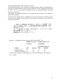
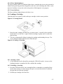
TM
TKZ60 Installation/User’s Manual
Order Number: EK-A0662-IN.001
Digital Equipment Corporation
The information in this document is subject to change without notice and should not be
construed as a commitment by Digital Equipment Corporation.
Digital Equipment Corporation assumes no responsibility for any errors that may appear in
this document. No responsibility is assumed for the use or reliability of software on
equipment that is not supplied by Digital Equipment Corporation or its affiliated companies.
Restricted rights: Use, duplication, or disclosure by the U.S. Government is subject to
restrictions as set forth in subparagraph (c) (1) (ii) of the Rights of Technical Data and
Computer Software clause at DFARS 252.227-7013.
The Digital logo, OpenVMS, VAX, AXP, ULTRIX and DECwrite are all trademarks of the
Digital Equipment Corporation
All third-party trademarks are acknowledged as the proprietary property of their respective
owners.
Copyright © 1993 Digital Equipment Corporation. All rights reserved
This document was prepared, printed and published by The Digital Equipment Corporation,
using DECwrite V2.0
ii
Federal Communications Commission (FCC) Notice
This equipment generates, uses, and may emit radio frequency energy. The equipment has
been type tested and found to comply with the limits for a Class A digital device pursuant
to Part 15 of FCC rules, which are designed to provide protection against such radio
frequency interference.
Any changes or modifications made to this equipment may void the user’s authority to
operate this equipment.
Operation of this equipment in a residential area may cause interference in which case the
user at his own expense will be required to take whatever measures may be required to
correct the interference.
Acoustics - Preliminary declared values per ISO 9296 and ISO 7779:
Sound Power Level Sound Pressure Level
LWAd, B
LpAm, dBA
(bystander positions)
Product
Idle
Operate
Idle
Operate
TKZ60 (tabletop)
5.8
5.8
46
46
TKZ60 (rack-mount) 5.8
5.8
39
40
[Current values for specific configurations are available from Digital representatives.
1 B = 10 dBA.]
iii
..
Fur Bundesrepublik Deutschland
For Federal Republic of Germany
Pour la Republique federale d’Allemagne
VDE Statement
BESCHEINIGUNG DES HERSTELLERS/IMPORTEURS
..
..
Dieses gerat ist in Ubereinstimmung mit den Bestimmungen der BMPT Vfg.243/1991 und
Vfg.46/1992 in Verbindung mit EN55022:1987 (DIN VDE 0878-3:11.89), oder
..
..
Vfg.1046/1984 mit Vfg.483/1986, funkenstort. es tragt als Nachweis der
..
..
EMV-Konformitat entweder eine Konformitatskennzeichnung oder das freiwillige
VDE-Funkschutzzeichen.
..
..
Der vorschriftsmaβige betreib mancher Gerate (z.B Meβsender) kann
..
allerdingsgewissen Einschrankungen untrliegen. Beachten Sie deshalb die
..
unten aufgefuhrten Hinweise.
..
..
Fur Gerate die nicht mit dem VDE-Funkschutzzeichen versehen sind
..
wurde dem Bundesamt fur Zulassungen in der Telekommunikation (BZT)
das Inverkehrbringen diesses Gerates angezeigt und die Berechtigung zur
..
..
..
Uberprufung der Serie auf Einhaltung der Bestimmungen eingeraumt.
Betreiberhinweis
Wir sind verpflichet, Sie auf folgende Fakten hinzuweisen (BMPT..
Amtsblattverfugung
243/91 bzw. 1046/84 δ2, Abschnitt 5):
..
..
..
..
Dieses Gerat wurde funktechnisch sorgfaltig entstort und gepruft. Wird dieses
..
..
Gerat innerhalb einer Anlage zusammen mit anderen Geraten betrieben, muβ bei
Inannspruchnahme der "Allgemeinen Betriebsgenehmigung" nach
BMPT-AmtsblVfg 243/91 bzw. 1046/84 die gesamte Anlage den unter δ2,
Abschnitt 1, genannten Voraussetzungen entsprechen.
Externe Datenkabel
..
Solite ein Austausch der von Digital spezifizierten Datenkabel notig werden,
..
..
muβ der Betreiber fur eine einwandfreie Funkentstorung sicherstellen, daβ
..
Austauschkabel im Aufbau und Abschirmqualitat dem Digital Originalkabel
entsprechen.
Schallemissionswerte - Vorläufige Werteangaben nach ISO 9296 und
ISO 7779/DIN EN27779:
Schalleistungspegel Schalldruckpegel
LWAd, B
LpAm, dBA
(Zuschauerpositionen)
Gerät
Leerlauf Betrieb
Leerlauf Betrieb
TKZ60 (tabletop)
5,8
5,8
46
46
TKZ60 (rack-mount) 5,8
5,8
39
40
[Aktuelle Werte für spezielle Ausrüstungsstufen sind über die Digital Equipment
Vertretungen erhältlich. 1 B = 10 dBA.]
iv
Contents
Preface .................................................................................................................................ix
Introduction.....................................................................................................................xi
Manual Structure ............................................................................................................xi
Intended Audience ..........................................................................................................xi
Related Documents .........................................................................................................xi
1 - Introduction to this Document ........................................................................ 1.1
1.1 Document Overview............................................................................................. 1.3
2 - Installation ............................................................................................................. 2.1
2.1 Introduction .......................................................................................................... 2.3
2.1.1 Prerequisites .......................................................................................... 2.3
2.2 Unpacking ............................................................................................................ 2.3
2.3 Tabletop Installation ............................................................................................. 2.4
2.4 Rack Mounting ..................................................................................................... 2.4
2.4.1
2.4.2
2.4.3
2.4.4
2.4.5
Introduction ........................................................................................... 2.4
Installation ............................................................................................. 2.5
Cooling .................................................................................................. 2.8
Dimensions ........................................................................................... 2.8
Weight ................................................................................................... 2.8
2.5 Table-Top Enclosure Mounting........................................................................... 2.9
2.5.1 Installation ............................................................................................. 2.9
2.6 Cabling ............................................................................................................... 2.10
2.6.1
2.6.2
2.6.3
2.6.4
Introduction ......................................................................................... 2.10
Interface Cable .................................................................................... 2.10
Bus Termination .................................................................................. 2.11
Power Cord. ......................................................................................... 2.11
3 - Configuration ........................................................................................................ 3.1
3.1 Introduction .......................................................................................................... 3.3
3.1.1 Factory Configuration ........................................................................... 3.3
3.1.2 Reconfiguration Procedure .................................................................... 3.3
3.2
Configuration Steps ............................................................................................. 3.5
v
3.3 Initial Power-Up - All Versions........................................................................... 3.6
3.4 Programming the SCSI Address - All Versions................................................... 3.7
3.5 Programming the Vendor ID - All Versions........................................................ 3.8
3.6 Programming the Product ID - OpenVMS Versions 5.4-1 to 5.5-1
..................... 3.9
3.7 Programming the Product ID - OpenVMS Versions 5.5-2 and Higher &
OpenVMS AXP ......................................................................................................... 3.10
3.8 Programming the Product ID - OSF/1 V1.3 (or Higher).................................... 3.11
3.9 Programming The Density - All Versions ......................................................... 3.12
3.10 Verifying The Configuration Table - All Versions.......................................... 3.13
3.11 Verifying The SCSI Address- All Versions..................................................... 3.16
4 - Using the Unit ....................................................................................................... 4.1
4.1 Introduction .......................................................................................................... 4.3
4.2 Switches and Indicators ........................................................................................ 4.3
4.3 Switches................................................................................................................ 4.3
4.4 Switch Functions .................................................................................................. 4.4
4.4.1 UNLOAD Switch .................................................................................. 4.4
4.4.2 FORMAT Switch .................................................................................. 4.4
4.4.3 Power Switch ......................................................................................... 4.4
4.5 Indicator Functions ............................................................................................... 4.4
4.5.1
4.5.2
4.5.3
4.5.4
4.5.5
Hexadecimal Display ............................................................................ 4.4
Fault Indicator ....................................................................................... 4.4
Active Indicator ..................................................................................... 4.4
Write-Enable Indicator.......................................................................... 4.5
Power Indicator ..................................................................................... 4.5
4.6 Loading a Cartridge .............................................................................................. 4.5
4.6.1 Aborting a Load..................................................................................... 4.5
4.6.2 Unloading a Cartridge ........................................................................... 4.5
4.7 Operation With Automatic Cartridge Loader (ACL) Installed ............................ 4.6
4.7.1
4.7.2
4.7.3
4.7.4
4.7.5
4.7.6
vi
Inserting Cartridges into a Magazine .................................................... 4.6
Loading a Magazine .............................................................................. 4.6
Unloading a Magazine........................................................................... 4.6
Aborting ACL Operation....................................................................... 4.7
Manual Operation .................................................................................. 4.7
Removing a Trapped Cartridge ............................................................. 4.7
4.8 OpenVMS - Systems Operation & Test............................................................... 4.8
4.8.1 System Diagnostics ............................................................................... 4.8
4.8.2 System Operation .................................................................................. 4.8
4.9 ULTRIX & OSF/1 - Systems Operation & Test.................................................. 4.8
4.9.1 System Diagnistics ................................................................................ 4.8
4.9.2 System Operation .................................................................................. 4.8
5 - Troubleshooting ................................................................................................... 5.1
5.1 Introduction .......................................................................................................... 5.3
5.2 Routine Maintenance ............................................................................................ 5.4
5.2.1 Tape Path ............................................................................................... 5.4
5.2.2 Tape Accessories .................................................................................. 5.4
List of Figures
Figure 2.1 Shelf Slide (Right Side) ............................................................................ 2.5
Figure 2.2 Shelf Tray.................................................................................................. 2.6
Figure 2.3 Front Panel ................................................................................................ 2.7
Figure 2.4 Tape Drive Dimensions ............................................................................ 2.8
Figure 2.5 Table-Top Enclosure................................................................................. 2.9
Figure 2.6 Shielded SCSI Connector ....................................................................... 2.10
Figure 2.7 Rear Panel Interface Connections ........................................................... 2.11
Figure 3.1 Unit Power Connection and Switch .......................................................... 3.6
Figure 3.2 Front of the Unit........................................................................................ 3.6
Figure 4.1 Front Panel ................................................................................................ 4.3
Figure 4.2 Rear Panel ................................................................................................. 4.3
Figure 4.3 On/Off Switch Detail ................................................................................ 4.4
Figure 4.4 Indicators .................................................................................................. 4.4
Figure 4.5 Cartridge Detail ......................................................................................... 4.5
Figure 4.6 Loading A Cartridge ................................................................................. 4.5
Figure 4.7 Unit with Automatic Cartridge Loader ..................................................... 4.6
List of Tables
Table 2.1 Container Contents .................................................................................... 2.3
Table 3.1 Configuration Parameters ........................................................................... 3.4
Table 3.2 Data Content ............................................................................................. 3.14
Table 3.3 Device Configuration Parameters ............................................................ 3.15
Table 5.1 Error Code Translation Table - Tape Drive............................................... 5.3
Table 5.2 Error Code Translation Table - ACL......................................................... 5.4
Table 5.3 Recommended Tape Accessories ............................................................... 5.4
vii
viii
Preface
ix
x
Introduction
This manual describes how to install and use the TKZ60 family of Tape Drives and
Automatic Loaders. The available configurations are detailed below:
• TKZ60-AA, Rack-mount, Without Loader
• TKZ60-AC, Rack-mount, With Loader - 5 or 10 slot magazine
• TKZ60-BA, Table-top, Without Loader
• TKZ60-BC, Table-top, With Loader - 5 or 10 slot magazine
This manual can also be used for the following custom-quoted variants:
• 2E/2R-TKZ60-CA TKZ60-AA but with Differential SCSI
• 2E/2R-TKZ60-CC TKZ60-AC but with Differential SCSI
• 2E/2R-TKZ60-DA TKZ60-BA but with Differential SCSI
• 2E/2R-TKZ60-DC TKZ60-BC but with Differential SCSI
Manual Structure
This manual is divided into two main areas which cover the installation and use.
The manual is organised as follows:
• Chapter One - Overview and Introduction to this document
• Chapter Two - Installation Procedures
• Chapter Three - Configuration for Host Operating System
• Chapter Four - Using the Unit
• Chapter Five - User Troubleshooting and Maintenance
Intended Audience
This manual is for the use of personnel installing and using the TKZ60-xx family
Related Documents
•
•
•
•
TKZ60 Service Manual (EK-A0662-SM.001)
TKZ60 Pocket Service Card (EK-A0662-PG.001)
KZQSA Module Installation Guide (EK-KZQSA-IG)
MicroVAX Diagnostic Monitor User’s Guide (AA-FM7AE-DN)
xi
xii
1 - Introduction to this Document
1.1
1.2
1.1 Document Overview
This manual is a combined Installation and User document.
The Installation procedure describes both rack mounting and custom installation, with the
addition of installing into the optional table-top enclosure.
The cabling and configuration covers the interfacing and drive configuration.
The User information covers both routine use of the unit and simple User-level
troubleshooting and maintenance.
1.3
1.4
2 - Installation
2.1
2.2
2.1 Introduction
This chapter describes how to unpack and install the Table-top and Rack-mount versions of
the TKZ60 and how to fit the unit into Rack-Mount enclosure (TK60R-AA) and optional
Table-Top enclosure (TK60E-AA).
2.1.1 Prerequisites
For rack mount installation, the Rack-Mount enclosure TK60R-AA is required.
For units fitted with the Automatic Cartridge Loader (ACL), one or more 5 or 10 cartridge
magazines (TK60K-AB/BB) will be required.
For ALL installations outside of the North America, a country specific power cord is
required.
For ALL installations, an appropriate SCSI cable of the required length and connector type
for the installation will be required.
2.2 Unpacking
The unit and accessories are delivered in a single container. .
Table 2.1 Container Contents
Part Number
TKZ60-xx
Description
TKZ60 Tape drive
EK-A0662-UG.001 Installation/User’s Manual (this document)
30-29907-01
Cartridge, Magnetic tape half inch
30-30326-01
3480 Cleaning cartridge
12-30552-01
SCSI Terminator (single ended)
FW-USIK0-HP1.0
TKZ60 ULTRIX Software Kit (Shipped with ACL variants only)
17-00083-26
North American power cord
The following optional items will each be supplied in their own separatate packaging
containers.
TK60K-AB
5 Cartridge magazine
TK60K-BB
10 Cartridge magazine
TK60R-AA
Rack Mount Kit (mounts up to two drives)
TK60U-AB
Data Compression upgrade (future)
An upgrade kit for non-ACL to ACL (2E/2R-TK60L-AA) and a Table-top enclosure
upgrade kit for rack-mount to table-top conversion (2E/2R-TK60E-AA) are also available
on special quotation only.
2.3
2.3 Tabletop Installation
For table-top installation without loader, the unit will require a space of 625mm (25") deep
by 225mm (9") wide, to allow sufficient space at the rear of the unit for cabling and
ventilation.
For table-top installation with loader, a further 200mm (8") of depth is required.
If the table-top unit is required to be used with the 10 cartridge magazine (TK60K-BB), then
the loader mechanism must overhang the front of table. This should be done by placing the
table in a position such that the protruding loader does not cause an hazard.
For cabling information see Section 2.5 and for configuration see Section 3
2.4 Rack Mounting
Caution: Before commencing rack installation, ensure that the 19" rack stabilizer foot
(feet) is extended and secured to prevent rack toppling and damaging the TKZ60.
2.4.1 Introduction
The tape drive is designed to be rack mounted in a standard 19 inch EIA/RETMA rack or
cabinet with a depth of 24 to 30 inches.
All of the necessary mounting hardware is provided with the optional rack mounting kit,
Part Number TK60R-AA for installing 1 or 2 drives.
2.4
2.4.2 Installation
NOTE: When the rails have threaded holes, use the nut plate with the smaller holes and the
corresponding screws and washers.
When the holes in the rails are not threaded, use the nut plate with the larger holes and the
corresponding screws and washers.
Please follow the installation procedure in the order listed below.
Installation Procedure
1. Locate the front and rear rail holes of the cabinet or equipment rack where the drive
is to be installed.
2. Loosely assemble each shelf slide and angle bracket for the approximate depth of
the rack using four screws with washers and nuts, as shown below
Figure 2.1 Shelf Slide (Right Side)
3. Loosely assemble each shelf slide to the front rail of the rack using two screws with
washers and a nut plate as shown in Figure 2-1 above.
4. Loosely assemble each shelf slide with angle bracket to the rear rail of the rack
using two screws and a nut plate as shown in Figure 2-1 above.
5. Slide the shelf tray onto the shelf slides.
6. Tighten the four screws securing the front rails to the shelf slide.
7. Tighten the four screws securing the rear rails to the angle bracket.
2.5
8. Slide the shelf tray in and out several times, ensuring that the rack latch engages and
that the shelf does not bind against the slides.
Figure 2-2 (below) shows the location of the rack latch.
Figure 2.2 Shelf Tray
9. Tighten the eight screws securing the shelf slides to the angle brackets.
10. Remove the shelf tray from the rack, then remove the four screws (two on each
side) attaching the front support bar to the shelf tray. Refer to Figure 2-2 (above)for
location of the support bar.
2.6
11. Set the tape drive in the left compartment. If two drives are being installed, set the
second one in the right side.
12. Reinstall the front support bar.
13. Attach the support bracket to the rear of the drive(s) using one screw, with the flat
end of the bracket against the drive(s) as shown in Figure 2-2.
14. Attach the rear support bar to the support bracket using one screw as shown in
Figure 2-2.
15. While supporting the tape drive and the shelf tray, turn both upside down. Using
four screws, attach the shelf tray to the tape drive as shown in Figure 2-2.
16. If required, install the two standoffs to the front rails to allow for correct spacing
between the front rails and the shelf tray.
The standoffs are shown in Figure 2-1.
17. Set the shelf tray on the shelf slides and slide it into the rack.
18. Attach the ballstuds as shown in Figure 2-3 (below).
Figure 2.3 Front Panel
19. The blank plate is used when a second drive has not been installed.
To replace the plate, remove the two nuts on the rear of the front panel.
20. Attach the front panel to the ballstuds. If the front panel does not fit flush against
the drive, adjust the drive’s position within the shelf tray as necessary.
21. Connect the interface and power cables.
Be sure to provide a service loop that allows the shelf tray to be extended fully.
2.7
2.4.3 Cooling
A minimum clearance of 2 inches is required between the rear panel and any surface or
object. The front panel must not be covered in such a way that airflow would be restricted.
2.4.4 Dimensions
The following figure shows the dimensions of the drive:
Figure 2.4 Tape Drive Dimensions
2.4.5 Weight
The unit weighs 11.3 kg ( 25 pounds) without loader or 13.6Kg (30 pounds) with loader.
2.8
2.5 Table-Top Enclosure Mounting
The following paragraphs describe how to install the tape drive into an optional table-top
enclosure (TK60E-AA).
2.5.1 Installation
Please refer to the following figure while installing the tape drive in the enclosure.
Figure 2.5 Table-Top Enclosure
1. Slide the top cover of the enclosure rearward to clear the locking tabs,
then lift it off.
2. Set the tape drive into the enclosure.
3. Attach the tape drive within the enclosure with the two smaller screws.
4. Slide the top cover of the enclosure onto the botton so the tabs lock.
5. Attach the top cover to the drive in the rear with the single larger screw.
2.9
2.6 Cabling
2.6.1 Introduction
This chapter explains how to connect the interface and power cables, and how to terminate
the interface bus properly.
2.6.2 Interface Cable
For single-ended applications a 25 signal twisted-pair cable is required. The maximum cable
length is six metres.
NOTE: The recommended cable for connection to other SCSI devices and to some, but not
all processors connectors, is the BC06P-06 which is 1.8 metres (6 feet) long with 50-way
CHAMP connectors at each end. Other processor interfaces have different connector types
(50 or 68 way miniature) and for connection to these or systems needing different cable
lengths, the appropriate cable type should be used.
For differential applications a 25 signal twisted-pair cable is required. The recommended
cable is BC13N-25, which is 25 feet long (7.8m), the maximum cable length allowed is 25
metres.
Figure 2.6 Shielded SCSI Connector
The interface connectors are located on the rear panel as shown in the following figure:
2.10
Figure 2.7 Rear Panel Interface Connections
2.6.3 Bus Termination
A bus terminator must be at each end of the SCSI bus. If the tape drive is at either end of the
bus, a terminator plug must be installed in the unused SCSI cable connector at the rear of the
drive.
NOTE: A different SCSI terminator is required for single ended or differential SCSI.
Ensure that the appropriate terminator is used.
2.6.4 Power Cord.
The autoranging power supply selects the appropriate voltage and frequency range
automatically. The power cord connects to the rear panel, as shown in Figure 2-7.
2.11
2.12
3 - Configuration
3.1
3.2
3.1 Introduction
The configuration sequences described in this Chapter are for the following Operating
Systems:
• OpenVMS Systems Version 5.4-1 to 5.5-1
• OpenVMS VAX Systems Version 5.5-2 and higher , & OpenVMS AXP V1.0
and higher versions
• ULTRIX Systems Version 4.2a and higher versions
• OSF/1 V1.3 and higher versions
3.1.1 Factory Configuration
The drive is shipped from the factory configured as listed in Table 3-1. This is the setting
required for ULTRIX 4.2a, OpenVMS 5.5-2 and higher and OpenVMS AXP systems
without Automatic Cartridge Loader (ACL) support. If those default configuration
parameters are acceptable, the drive can be operated once it has been installed. If, however,
the default configuration parameters are not optimised for the system, the following
configuration procedure can be used to change them.
3.1.2 Reconfiguration Procedure
This procedure changes the configuration parameters.
1. If a cartridge is loaded in the drive, unload it.
2. While pressing the UNLOAD switch, press and release the FORMAT switch.
3. Release the UNLOAD switch; the hexadecimal display shows code 00.
4. Press the FORMAT switch to increment the hexadecimal display to code 09.
5. While pressing the UNLOAD switch, press and release the FORMAT switch.
6. Release the UNLOAD switch. The hexadecimal display shows code 10.
7. Press the FORMAT switch to increment the hexadecimal display to the desire
configuration parameter code; refer to Table 3-1.
Press the FORMAT switch while pressing the UNLOAD switch to decrement to the
desired configuration parameter code; refer to Table 3-1.
8. Press the UNLOAD switch to enter the edit mode for the selected configuration
parameter. The numeric code for current configuration setting appears at the
hexadecimal display.
9. Press the FORMAT switch to increment to the next available setting for the
parameter.
10. Once the desired setting is reached, press the UNLOAD switch to save it. The new
setting flashes twice on the hexadecimal display, then the code for this
configuration parameter appears.
11. Repeat steps 7 and 10 for each configuration parameter to be changed.
12. Press the UNLOAD switch for at least two seconds to exit the configuration
procedure.
A detailed step-by -step procedure for set-up with the different Digital operating systems is
included in the following paragraphs.
3.3
Table 3.1 Configuration Parameters
Code Configuration Parameter
Parameter Settings
Default
42
Power-up restart
1 = unload cartridge, 2 = load cartridge
1
43
Format display
1 = enable, 2 = disable
1
44
Write synchronisation
0 = synchronisation
1 = synchronise on 1 filemark
2 = synchronise on 2 consecutive filemarks
3 = synchronise on every write
2
45
Write syncronisation before reverse
1 = enable, 2 = disable
2
46
Number of read error retries
3 = 4 Retries, 4 = 8R, 5 = 16R, 6 = 32 R
4
47
Number of write error retries
1 = 1 Retry, 2 = 2R, 3 = 4R, 4 = 8R, 5 = 16R
5
49
Block size
0 = variable block mode, 1 = 4 Bytes,
2 = 8B, 3 = 16B, 4 = 32B, 5 = 64B,
6 = 128B, 7 = 256B, 8 = 512B, 9 = 1kB,
10 = 2kB, 11 = 4kB, 12 = 8kB, 13 = 16kB,
14 = 32kB, 15 = 64kB
0
50
Address
0 to 7
4
51
Interface parity
1 = enable, 2 = disable
1
53
Rewind ready
1 = enable, 2 = disable
1
60
Vendor ID
5 = DEC
5
61 1
Product ID
11 = TSZ07, 16 = TKZ60, 17 = TKZ60L,
18 = TKZ60C, 19 = TKZ60CL
16
62
Density
0 = 1600 bpi, 1 = 6250 bpi, 2 = 3480
2
63
Interface Options
00 = Default SCSI, 1 -1 15 = Special SCSI
0
64
EOD Detect length
1 = short, 2 = long
1
66 2
Linked load/unload
0 = normal, 1 = enable
0
Allow MTEC
1 = enable, 2 = disable
2
67
69 3
Default compression/uncompression 1 = uncompress 2 = compress
1
Code 61 parameter settings 18 and 19 are for future products with data compression
2
Code 66 is only applicable set to a ’1’ if ACL installed. Should be set to ’0’ (as indicated
above) if no ACL is installed
3
Code 69 is for future product with data compression
3.4
3.2 Configuration Steps
There are a series of steps in the configuration procedure for each type of Operating System
that are common. These will only be reproduced here once for clarity. The following chart
shows the procedure for each Operating System type.
.
Turning
Power On
ALL
Program
SCSI
Address
ALL
Program
Vendor ID
ALL
Program
Product ID
OSF/1
Program
Product ID
OpenVMS
5.4-1 to 5.5-1
Program Product ID
OpenVMS VAX 5.5-2 Up
OpenVMS AXP 1.0 Up
ULTRIX 4.2 a Up
Program the
Density
ALL
Verify
Config Table
ALL
Verify SCSI
Address
ALL
3.5
3.3 Initial Power-Up
- All Versions
Please use the following sequence for powering-up your unit:
1. Check that the unit is connected to the correct power source, and that the power
supply is on
2. Check that there is not a tape loaded in the unit
3. Switch ON the unit with the rear mounted On/Off rocker switch (press the top of the
switch which is marked with a | in for the ON position)
NOTE: The display will show random data and then go blank after approximately 20
seconds.
Figure 3.1 Unit Power Connection and Switch
NOTE: If a tape had been left in the unit, it would be ejected on power-up, and should be
carefully removed.
The next illustration shows the front of the unit and location of the UNLOAD and
FORMAT control buttons, as well as the Tape Cartridge slot.
Figure 3.2 Front of the Unit
3.6
3.4 Programming the SCSI Address
- All Versions
NOTE: It is essential that the next steps are followed in the sequence defined.
1. Press and hold the UNLOAD button, and then
the FORMAT button. The display will stay
blank
2. Release first the FORMAT and then the
UNLOAD button The display will then read
00.
3. Press the FORMAT button nine (9) times (until
09 is displayed)
4. Press and hold the UNLOAD button, and then
the FORMAT button. The display will still
show 09
5. Release first the FORMAT and then the
UNLOAD button The display will then read
10
6. Press the FORMAT button fourty (40) times
(until 50 is displayed)
NOTE: The display number will increment if the
FORMAT button is kept pressed (in a similar
manner to a digital watch). You can keep it
pressed until 40 or 41 is displayed, and then step
to 50 with single depressions of the FORMAT
button.
7. Press and hold the UNLOAD button for just
one (1) second, the display will read from 00 to
07
NOTE: Pressing and holding the UNLOAD
button for more than 2 seconds will take you out
of the CONFIGURATION mode, which will
require repeating of the process from Step One
8. Press the FORMAT button until the display
reads 04. This is the normal SCSI address for
Digital OpenVMS and ULTRIX systems. If a
different address is needed, just continue
pressing the FORMAT button until the
required address is displayed
9. Press and hold the UNLOAD button for just
one (1) second, the display will flash to
indicate that a save is being made (the number
flashing will be the selected SCSI number)
10. Zeros (00) in the display show that you are
ready for the next sequence.
PRESS & HOLD
1st
1
UNLOAD
2nd
FORMAT
RELEASE
2nd
2
UNLOAD
1st
FORMAT
PRESS
9 TIMES
UNLOAD
3
FORMAT
PRESS & HOLD
1st
4
2nd
UNLOAD
FORMAT
RELEASE
2nd
5
FORMAT
PRESS
40 TIMES
UNLOAD
6
7
FORMAT
PRESS &
HOLD
ONE
SECOND
ONLY
PRESS
X TIMES
8
9
UNLOAD
1st
UNLOAD
FORMAT
UNLOAD
FORMAT
PRESS &
HOLD
ONE
SECOND
UNLOAD
FORMAT
ONLY
UNLOAD
10
FORMAT
3.7
3.5 Programming the Vendor ID
- All Versions
1. Press the FORMAT button fifty one (51)
times (until 60 is displayed)
NOTE: The display number will increment if
the FORMAT button is kept pressed (in a
similar manner to a digital watch). You can
keep it pressed until 50 or 51 is displayed, and
then step to 60 with single depressions of the
FORMAT button.
2. Press and hold the UNLOAD button for just
one (1) second, the display will read from
00 to 10
NOTE: Pressing and holding the UNLOAD
button for more than 2 seconds will take you
out of the CONFIGURATION mode, which
will require repeating the process from Step
One
3. Press the FORMAT button until the display
reads 05. The display will sequence from 01
to 10 and back to 01, depending how many
time the FORMAT button is pressed.
4. Press and hold the UNLOAD button for just
one (1) second, the display will flash to
indicate that a save is being made (the
number flashing will be the selected ID
number)
5. Zeros (00) in the display show that you are
ready for the next sequence
3.8
PRESS
51 TIMES
1
2
FORMAT
PRESS &
HOLD
ONE
SECOND
ONLY
PRESS
X TIMES
3
4
UNLOAD
UNLOAD
FORMAT
UNLOAD
FORMAT
PRESS &
HOLD
ONE
SECOND
ONLY
UNLOAD
FORMAT
UNLOAD
5
FORMAT
3.6 Programming the Product ID
- OpenVMS Versions 5.4-1 to 5.5-1
1. Press the FORMAT button fifty two (52)
times (until 61 is displayed)
NOTE: The display number will increment if
the FORMAT button is kept pressed (in a
similar manner to a digital watch). You can
keep it pressed until 50 or 51 is displayed, and
then step to 61 with single depressions of the
FORMAT button.
2. Press and hold the UNLOAD button for just
one (1) second, the display will read from
00 to 15
NOTE: Pressing and holding the UNLOAD
button for more than 2 seconds will take you
out of the CONFIGURATION mode, which
will need you to repeat the process from Step
One
3. Press the FORMAT button until the display
reads 11. The display will sequence from 01
to 15 and back to 01, depending how many
time the FORMAT button is pressed.
4. Press and hold the UNLOAD button for just
one (1) second, the display will flash to
indicate that a save is being made (the
number flashing will be the selected ID
number)
5. Zeros (00) in the display show that you are
ready for the next sequence
PRESS
52 TIMES
1
UNLOAD
FORMAT
PRESS &
HOLD
2
ONE
SECOND
ONLY
UNLOAD
FORMAT
PRESS
X TIMES
3
4
5
UNLOAD
FORMAT
PRESS &
HOLD
ONE
SECOND
ONLY
UNLOAD
FORMAT
UNLOAD
FORMAT
3.9
3.7 Programming the Product ID
- OpenVMS Versions 5.5-2 and Higher & OpenVMS AXP
1. Press the FORMAT button fifty two (52)
times (until 61 is displayed)
NOTE: The display number will increment if the
FORMAT button is kept pressed (in a similar
manner to a digital watch). You can keep it
pressed until 50 or 51 is displayed, and then step
to 61 with single depressions of the FORMAT
button.
2. Press and hold the UNLOAD button for just
one (1) second, the display will read from 00
to 15
PRESS
UNLOAD
1
2
3
NOTE: Pressing and holding the UNLOAD
button for more than 2 seconds will take you out
of the CONFIGURATION mode, which will
require repeating the process from Step One
3. Press the FORMAT button until the display
reads 16 or 17. The display will sequence
from 01 to 17 and back to 01 (or on a drive
that supports compression, from 01 to 20),
depending how many time the FORMAT
button is pressed.
Selecting 16 sets the product to TKZ60.
If the tape drive has a loader attached, and the
system is using OpenVMS Version 6.0 or
higher or OpenVMS AXP V1.0 or higher,
press the FORMAT button until 17 is
displayed (this sets the product ID to
TKZ60L)
4. Press and hold the UNLOAD button for just
one (1) second, the display will flash to
indicate that a save is being made (the number
flashing will be the selected ID number, 16
for TKZ60 or 17 for TKZ60L)
5. Zeros (00) in the display show that you are
ready for the next sequence
3.10
OR
52 TIMES
FORMAT
PRESS &
HOLD
ONE
SECOND
ONLY
PRESS
X TIMES
OR
FORMAT
UNLOAD
FORMAT
PRESS
X TIMES
UNLOAD
FORMAT
PRESS &
HOLD
ONE
4
UNLOAD
SECOND
ONLY
PRESS &
HOLD
ONE
SECOND
ONLY
UNLOAD
FORMAT
UNLOAD
FORMAT
UNLOAD
5
FORMAT
3.8 Programming the Product ID
- OSF/1 V1.3 (or Higher)
1. Press the FORMAT button fifty two (52)
times (until 61 is displayed)
NOTE: The display number will increment if
the FORMAT button is kept pressed (in a
similar manner to a digital watch). You can
keep it pressed until 50 or 51 is displayed, and
then step to 61 with single depressions of the
FORMAT button.
2. Press and hold the UNLOAD button for just
one (1) second, the display will read from
00 to 16
NOTE: Pressing and holding the UNLOAD
button for more than 2 seconds will take you
out of the CONFIGURATION mode, which
will require repeating the process from Step
One
3. Press the FORMAT button until the display
reads 16, 17, 18 or 19. The display will
sequence from 01 to 17 and back to 01 (or
on drives that support compression from 01
to 20) depending on how many times the
FORMAT button is pressed.
Select 16 for products without loader.
Select 17 for products with loader.
Select 18 for products that support
compression.
Select 19 for products with loader and
compression
4. Press and hold the UNLOAD button for just
one (1) second, the display will flash to
indicate that a save is being made (the
number flashing will be the selected ID
number)
5. Zeros (00) in the display show that you are
ready for the next sequence
PRESS
52 TIMES
1
UNLOAD
FORMAT
PRESS &
HOLD FOR
UNLOAD
2
ONE SECOND
PRESS X
3
TIMES
PRESS X
OR
TIMES
PRESS X
OR
OR
FORMAT
ONLY
TIMES
UNLOAD
FORMAT
UNLOAD
FORMAT
UNLOAD
FORMAT
PRESS X
UNLOAD
TIMES
FORMAT
PRESS &
HOLD FOR
UNLOAD
4
ONE SECOND
FORMAT
ONLY
XX
UNLOAD
5
FORMAT
XX = Number Entered
3.11
3.9 Programming The Density
- All Versions
1. Press the FORMAT button fifty three (53)
times (until 62 is displayed)
NOTE: The display number will increment if
the FORMAT button is kept pressed (in a
similar manner to a digital watch). You can
keep it pressed until 50 or 51 is displayed, and
then step up to 62 with single depressions of
the FORMAT button.
2. Press and hold the UNLOAD button for just
one (1) second, the display will read from
00 to 02
NOTE: Pressing and holding the UNLOAD
button for more than 2 seconds will take you
out of the CONFIGURATION mode, which
will require repeating the process from Step
One
3. Press the FORMAT button until the display
reads 02. This sets the tape drive density to
3480 mode (38,000 bpi).
4. Press and hold the UNLOAD button for just
one (1) second, the display will flash to
indicate that a save is being made
5. Zeros (00) in the display show that you are
ready for the next sequence
3.12
PRESS
UNLOAD
53 TIMES
1
2
FORMAT
PRESS &
HOLD
ONE
SECOND
ONLY
PRESS
X TIMES
3
4
UNLOAD
FORMAT
UNLOAD
FORMAT
PRESS &
HOLD
ONE
SECOND
ONLY
UNLOAD
FORMAT
UNLOAD
5
FORMAT
3.10 Verifying The Configuration Table - All Versions
NOTE: The contents of the configuration table will vary depending on the settings that you
have entered in the previous sequences (see Table 3.3).
1. Press and hold the UNLOAD button, then the
FORMAT button. The display will stay blank
2. Release first the FORMAT and then the
UNLOAD button The display will read 00.
3. Press the FORMAT button five (5) times
(until 05 is displayed)
4. Press and hold the UNLOAD button for
ONLY 1 second, the display will show the
data content of table entry number 1, this
should be 1
NOTE: Pressing and holding the UNLOAD
button for more than 2 seconds will take you out
of the CONFIGURATION mode, which will
require repeating the process from Step One
PRESS & HOLD
1st
1
UNLOAD
2nd
FORMAT
RELEASE
2nd
2
3
1st
PRESS
5 TIMES
PRESS &
HOLD
UNLOAD
FORMAT
UNLOAD
FORMAT
UNLOAD
FORMAT
4
5. Press and hold the FORMAT button. While
the FORMAT button is depressed, the display
shows verification of table entry number 2.
PRESS &
You are now checking the drive settings.
HOLD
5
6. Release the FORMAT button and the display
shows that the data content is 01. The drive is
set to unload when power is turned on.
RELEASE
7. Press and hold the FORMAT button. While
6
the format button is depressed, the display
shows verification of table entry number 3.
8. Release the FORMAT button and the display
PRESS &
shows that the data content is 02. The drive is
7-ON then
set to write synchronize on 2 filemarks.
RELEASE
9. Press and hold the FORMAT button. While
the format button is depressed, the display
XX = Number Entered
shows verification of table entry number 4.
10. Release the FORMAT button and the display shows that the data content is 02.
The drive is set to disable “write synchronization before reverse" or 01, "enable write
synchronisation before reverse"
11. Press and hold the FORMAT button. While the format button is depressed, the
display shows verification of table entry number 5
12. Release the FORMAT button and the display shows that the data content is 04.
The drive read error retry is set to 8
13. Press and hold the FORMAT button. While the format button is depressed, the
display shows verification of table entry number 6.
14. Release the FORMAT button and the display shows that the data content is 05.
The drive write error retry is set to 16.
15. Press and hold the FORMAT button. While the format button is depressed, the
display shows verification of table entry number 7.
UNLOAD
FORMAT
UNLOAD
FORMAT
UNLOAD
FORMAT
XX
3.13
16. Release the FORMAT button and the display shows that the data content is 00.
The drive is set to variable block sizes.
17. Press and hold the FORMAT button. While the FORMAT button is depressed, the
display shows verification of table entry number 8.
18. Release the FORMAT button and the display shows that the the vendor ID data is 05.
If the display is not 05, repeat the programming sequence. The drive’s ID is set to DEC.
19. Press and hold the FORMAT button. While the FORMAT button is depressed, the display
shows verification of table entry number 9.
20. Release the FORMAT button and the display shows that the data content as follows:.
Table 3.2 Data Content
Code
Product ID
Operating System(s)
11
TSZ07
OpenVMS VAX Versions 5.4-1 to 5.5-1
16
TKZ60
OpenVMS VAXVersions 5.5.2 upwards, OpenVMS AXP, OSF/1
17
TKZ60L
OpenVMS VAX Version 6.0, OpenVMS AXP, OSF/1
16
TKZ60
Version 4.2a onwards of ULTRIX
17
TKZ60L
Version 4.2a onwards of ULTRIX
18
TKZ60C
OSF/1 (with compression) 1
19
TKZ60CL
OSF/1 (with Loader and compression) 1
1 Future Product
21. Press and hold the FORMAT button. While the FORMAT button is depressed,
display shows verification of table entry number 10.
22. Release the FORMAT button and the display shows that the data content is 02.
The drive density is now set to 3480 mode (38,000bpi).
23. Press and hold the FORMAT button. While the FORMAT button is depressed,
display shows verification of table entry number 11.
24. Release the FORMAT button and the display shows that the data content is 01.
Short erase gap detect.
25. Press and hold the FORMAT button. While the FORMAT button is depressed,
display shows verification of table entry number 12.
26. Release the FORMAT button and the display shows that the data content is 00.
Link Load/Unload is disabled
27. Press and hold the UNLOAD button for 5 seconds. The display goes blank when
UNLOAD button is released. Note that the “active" display may appear momentarily.
3.14
the
the
the
the
Table 3.3 Device Configuration Parameters
Code
1
Configuration Parameter
Parameter Settings
01
Format display
01=enable, 02=disable
02
Power-up restart
01=unload cartridge, 02=load cartridge
03
Write synchronization
00=nosynchronisation, 01=synchronise on 1 filemark
02=synchronise on 2 consecutive filemarks
03=synchronise on every write
04
Write synchronization before reverse
01=enable, 02=disable
05
Number of read error retries
03=4 Retries, 4=8 R, 5=16 R, 6=32 R
06
Number of write error retries
01=1 Retry, 02=2 R, 03=4 R, 04=8R, 05=16 R
07
Block size
00=variable block mode, 01=4Bytes, 02=8B,
03=16B, 04=32B, 05=64B, 06=128B, 07=256B,
08=512B, 09=1kB, 10=2kB, 11=4kB, 12=8kB,
13=16kB, 14=32kB, 15=64kB
08
Vendor ID
01 = Cipher, 02 = NCR, 03 = HP, 04 = Fujitsu,
05 = DEC, 06 = STK, 07 = HPCipher, 08 = LMS,
09 = Exabyte, 10 = Kennedy
09
Product ID
01 = T480, 02 = M995, 03 = F880ES,
04 = 0-STD1-0, 05 = 88780, 06 = M1016A M2481A
07 = M1016B, 08 = M1016AD, 09 = M1016BD,
10 = TSZ05, 11 = TSZ07, 12 = 4280, 13 = 92160,
14 = EXB-8200, 15 = 96X2 Tape Unit,
16 = TKZ60, 17 = TKZ60L
1 18 = TKZ60C, 1 19 = TKZ60CL
10
Density
00 = 1600 Bpi, 01 = 6250 Bpi, 02 = 3480
11
EOD Detect length
01 = Short (3mm) special erase gap detect
02 = Long (134mm) special erase gap detect
12
Link Load/Unload
00 = Disable, 01 = Enable
Parameter settings 18 and 19 are for future products with compression
3.15
3.11 Verifying The SCSI Address
- All Versions
1. Press and hold the UNLOAD button and then the format button. The
display shows blank before the key sequence.
2. Release the FORMAT button and then the unload button. The display
reads 00.
3. Press the FORMAT button 06 times until the display reads 06.
4. Press and hold the UNLOAD button for only 1 second. The display
shows the present SCSI address. If the display is not showing the required
SCSI address (between 01 and 07), repeat the programming sequence
NOTE: Pressing and holding the unload button for more than 2
seconds will take you out of the configuration mode, and the entire
process will need to be repeated.
5. Press and hold the UNLOAD button for five (5) seconds.
PRESS &
The display will blank when the button is released.
HOLD
Please note that the "active" display may
FIVE
5
SECONDS
appear temporarily
UNLOAD
FORMAT
The task is now complete and the unit is in an initialized condition.
Continue with the general installation procedure for the tape drive or turn the
power off.
3.16
4 - Using the Unit
4.1
4.2
4.1 Introduction
This chapter contains all of the information that you require to use your unit. There is a
description of the controls and indicators that you will be using, and the procedures needed
to operate the drive and Automatic Cartridge Loader. Additional information is included to
help you with minor operational problems and limited routine maintenance.
4.2 Switches and Indicators
There are three switches used to control the tape drive and five indicators that allow it to
communicate information to the user.
Figure 4.1 Front Panel
4.3 Switches
Two switches, UNLOAD and FORMAT, are located on the front panel (shown above) and
a main AC Power On/Off switch located at the rear of the unit (see below).
Figure 4.2 Rear Panel
4.3
4.4 Switch Functions
4.4.1 UNLOAD Switch
The UNLOAD switch causes tape to be rewound into a cartridge and the cartridge to to be
ejected from the drive. The UNLOAD switch also resets the drive to clear a fault if it is
pressed without a cartridge loaded.
NOTE: The UNLOAD switch does not function when a cleaning cartridge is in the drive.
4.4.2 FORMAT Switch
Currently Field Service personnel use the FORMAT switch to execute diagnostics. Users
should not need to operate this switch. Later versions will use this switch for
compression/decompression enable.
4.4.3 Power Switch
The AC power switch (the on-off switch) is located on the rear panel, as shown below:
Figure 4.3 On/Off Switch Detail
ON
OFF
4.5 Indicator Functions
All of the indicators are located on the front panel (see Figure 4.1 on the previous page, and
the following detail)
Figure 4.4 Indicators
Hexadecimal
Display
Fault, Active &
Write Enable
Indicators
FAULT
ACTIVE
WRT EN
4.5.1 Hexadecimal Display
The two-digit hexadecimal LEDs indicate either a fault symptom code (Table 4.1 or 4.2) or
FO when a tape is loaded and configuration parameter Code 43 is set to enable.
4.5.2 Fault Indicator
The Fault indicator lights when a fault is detected (usually along with a fault symptom code
on the hexadecimal display).
4.5.3 Active Indicator
The Active Indicator lights after the following events:
• A tape motion command is being executed.
• A cleaning cartridge is inserted.
• A cartridge is being loaded or unloaded (the light flashes).
• During power on self testing until the drive is ready to accept a cartridge.
4.4
4.5.4 Write-Enable Indicator
The Write-Enable (WRT EN) indicator lights when a cartridge that is not write protected is
loaded. During the long and short diagnostics read/write tests, indicating that either a write
protected cartridge was ejected, or the write portion of the diagnostic is in progress.
4.5.5 Power Indicator
The Power indicator lights whenever the drive is on.
4.6 Loading a Cartridge
Check that the write-protect switch on the tape cartridge is in the correct position.
Figure 4.5 Cartridge Detail
1. Insert the tape cartridge into the drive as shown below, the hub is down and the
leader block is on the drive’s right. Slide the cartridge in gently until it reaches the
physical stop.
2. The drive automatically finishes loading the cartridge and threading the tape. The
Active indicator flashes while the drive loads the tape.
Figure 4.6 Loading A Cartridge
4.6.1 Aborting a Load
1. A load operation can be aborted by pressing the UNLOAD switch. As soon as the
loading operation is completed, the drive unloads the cartridge.
4.6.2 Unloading a Cartridge
1. Press the UNLOAD switch. Any uncompleted drive commands are completed, data
in the cache memory is written to tape, the tape is rewound, then the drive unthreads
the tape and ejects the tape cartridge.
2. Pull the tape cartridge out of the drive.
4.5
4.7 Operation With Automatic Cartridge Loader (ACL) Installed
This section explains how to operate the tape drive when an Automatic Cartridge Loader
(ACL) is installed.
Figure 4.7 Unit with Automatic Cartridge Loader
4.7.1 Inserting Cartridges into a Magazine
A magazine does not need to be fully loaded with cartridges to be used. When loading the
magazine, always begin loading with the top slot without skipping any slots until the desired
number of cartridges is loaded.
Insert cartridges into the magazine so that the front (end with the tape leader block and the
write-protect switch) is at the open end of the magazine.
Cleaning cartridges may be inserted into a magazine with data cartridges.
4.7.2 Loading a Magazine
1. Check that a cartridge is not in the drive; if one is, remove it. Align the rails on the
side of the magazine with the mating rails in the ACL.
2. Place the magazine into the ACL from the top, with the open end facing the front of
the tape drive.
3. Press the UNLOAD switch. The ACL lowers the magazine, then loads the cartridge
that is in the top slot of the magazine into the tape drive.
NOTE: Do not hold the UNLOAD switch pressed. If it is held for longer than 5 seconds,
the unit will enter into it’s diagnostic mode.
4.7.3 Unloading a Magazine
1. Check that the ACL is not loading or unloading a cartridge.
2. Remove the magazine from the ACL by lifting it up by the handle.
4.6
4.7.4 Aborting ACL Operation
ACL operation can be aborted at any time with this procedure:
1. Check that the ACL is not loading or unloading a cartridge.
2. Remove the magazine by lifting it up by the handle.
3. Press the UNLOAD switch to unload a cartridge in the drive.
Any uncompleted drive commands are completed, data in the cache memory is
written to tape, the tape is rewound, then the drive unthreads the tape and ejects the
tape cartridge.
4.7.5 Manual Operation
Individual cartridges may be manually loaded and unloaded into the tape drive if a magazine
is not loaded into the ACL. Operation is the same as if the ACL were not installed.
4.7.6 Removing a Trapped Cartridge
A cartridge trapped between the tape drive and the ACL magazine can be removed as
follows.
1. Insert a pencil or similar instrument into the access hole in the back of the magazine
and push the cartridge into the tape drive.
2. Remove the magazine from the ACL.
3. Press the UNLOAD switch to eject the cartridge.
NOTE: After All of the cartridges have been used in the magazine, you must remove it
completely and either reinsert it, or replace it with a fresh magazine, before further access to
the tapes can be made.
4.7
4.8 OpenVMS - Systems Operation & Test
4.8.1 System Diagnostics
For MicroVAX systems where the TKZ60 is connected via a KZQSA, the drive can be
tested using the MicroVAX Diagnostic Monitor (MDM). Consult the "MicroVAX
Diagnostic Monitor User’s Guide" for proper MDM operation. Make sure that the magnetic
tape that you use is blank or a scratch tape. Failure to do so may result in a loss of data.
MDM release 137 is the first version that recognises the TKZ60. If the unit is being used
with OpenVMS 5.4-1 to 5.5-1 and its device ID is set to TSZ07, then MDM release 135
onwards can be used.
For OpenVMS System, UETP should be run before using the tape drive. Log into the
SYSTEST account. Make sure the UETINIT.DAT file is set for the device number the tape
drive is set for. (The default for TKZ60 is "4"). If it is not, edit the file and change the
number. Initialise the tape drive UETP. "RUN UETTAPE00". The tape drive should run
through one pass without errors.
4.8.2 System Operation
OpenVMS VAX from V5.5-2 onwards and all versions of OpenVMS AXP, support the use
of the Automatic Cartridge Loader (ACL).
Please refer to the appropriate System Manuals for details of use.
4.9 ULTRIX & OSF/1 - Systems Operation & Test
4.9.1 System Diagnistics
To verify the operation of the tape drive on ULTRIX and OSF/1 systems, use either the
"tapex" or "mtx" diagnostics. For detailed descriptions of how to run these diagnostics, refer
to your ULTRIX or OSF/1 manuals.
4.9.2 System Operation
With OSF/1 systems, operating system support for the loader is not provided, although the
operating system accepts the device IDs of TKZ60L and TKZ60CL. These are needed for
other application software that can utilise the loader features.
The DUMP utility within ULTRIX V4.2a will operate with the loader provided the layered
CAM driver is loaded.
The DUMP utility within ULTRIX V4.3 will only work with the loader when the patch
FW-USIK0-HP1.0 has been installed
4.8
5 - Troubleshooting
5.1
5.2
5.1 Introduction
The drive will detect tape processing errors and hardware faults, and will identify them with
a series of codes displayed on the hexadecimal display.
The following tables shows what these codes mean and suggest a course of action to rectify
the problem. If a code is displayed on the unit that is not shown in the table, please make a
note of it and inform your service representative.
Table 5.1 Error Code Translation Table - Tape Drive
CODE
POSSIBLE CAUSE - SUGGESTED RECOVERY ACTION (TAPE DRIVE)
4C
Cartridge Write Protect set for read only - set to Write Enable
99
Data blocks larger than 64k cannot be read - check your data block sizes
8D
Tape cannot be written Clean tape path then retry. If this fails, try a new cartridge as the original
may be damaged. If still unable to write to tape, please contact your service representative.
8E
Multi-track error corrected - Clean tape path and retry. If this fails, try a new cartridge as the
original may be damaged. If still unable to write to tape, please contact your service representative.
C6
Block sequence error - this will usually indicate that a tape recorded in compressed format is
loaded into a drive that does not support compression
C8
Tape cannot be read - Clean tape path and retry. If this fails, try a new cartridge as the original
may be damaged. If still unable to read the tape, please contact your service representative.
C9
Tape format is incompatible - Check that your tape is of the correct format.
CC
I/O bus parity error - Check cable/connections and termination
5.3
Table 5.2 Error Code Translation Table - ACL
CODE
POSSIBLE CAUSE - SUGGESTED RECOVERY ACTION (ACL)
1
Magazine top slot is empty - Insert a cartridge
2
A magazine load has been attempted with a cartridge in the drive - remove the magazine and press
UNLOAD to eject the cartridge
4
The magazine was moved manually, aborting operation - remove the magazine and press
UNLOAD to eject the cartridge
6
ACL operation cannot be started. If a magazine from a previous operation is still loaded - remove
it and if operation still cannot be started, please call your service representative.
7
The drive did not accept the cartridge, the cartridge is in the drive and operation aborted, - remove
the magazine and press the UNLOAD switch
8
The drive did not accept the cartridge which ejected into the magazine and the operation aborted remove the magazine and reload it
9
The cartridge could not be unloaded into the magazine and was reloaded into the drive, operation
aborted - remove the magazine and press UNLOAD to eject the cartridge
A or B
The cartridge is trapped between the drive and magazine and operation aborted - use the
"Removing a trapped cartridge" procedure (4.7.6).
C
The magazine did not lower at the start of operation, which aborted - remove the magazine and
check that it is correctly loaded, and that there are no obstructions, then retry.
D
The magazine did not rise to the fully raised position and operation aborted - Carefully remove the
magazine
E or F
The ACL failed to initialise - remove the magazine and cycle OFF and ON the power to the drive.
If the problem still persists, please inform your service representative
5.2 Routine Maintenance
The following explains how to perform preventive maintenance to the tape drive, which is
limited to cleaning the tape path.
5.2.1 Tape Path
The tape path should be cleaned after approximately eight hours of tape motion across the
heads, using a high-quality cleaning cartridge. Please follow this procedure:
1. Load a cleaning cartridge into the tape drive (or into a slot in an Automatic
Cartridge Loader magazine) as you would a data cartridge.
2. On units without and Automatic Cartridge Loader, remove the cleaning tape after
the drive automatically ejects it.
5.2.2 Tape Accessories
Digital recommends the use of the following products to extend the life of your tape
transport:
Table 5.3 Recommended Tape Accessories
Digital Part Number
5.4
Description
TA90K-30
3480 Compatible Half-Inch Tape Cartridge (pack of 30)
TA90K-HC
Cleaning Cartridge (Pack of 5)