1
VAX 4000 Model 300
Technical Information
Order Number EK–337AB–TI–002
Digital Equipment Corporation
Maynard, Massachusetts
First Printing, March 1990
Revised, June 1991
The information in this document is subject to change without notice and should not be
construed as a commitment by Digital Equipment Corporation.
Digital Equipment Corporation assumes no responsibility for any errors that may appear in
this document.
The software, if any, described in this document is furnished under a license and may be used
or copied only in accordance with the terms of such license. No responsibility is assumed
for the use or reliability of software or equipment that is not supplied by Digital Equipment
Corporation or its affiliated companies.
Restricted Rights: Use, duplication or disclosure by the U.S. Government is subject to
restrictions as set forth in subparagraph (c)(1)(ii) of the Rights in Technical Data and Computer
Software clause at DFARS 252.227–7013.
©Digital Equipment Corporation, 1990, 1991. All rights reserved.
Printed in U.S.A.
The Reader’s Comments form at the end of this document requests your critical evaluation to
assist in preparing future documentation.
The following are trademarks of Digital Equipment Corporation: CompacTape, CX, DDCMP,
DEC, DECconnect, DECdirect, DECnet, DECscan, DECserver, DECUS, DECwindows,
DELNI, DEMPR, DESQA, DESTA, DSRVB, DSSI, IVAX, KDA, KLESI, MicroVAX, MSCP,
Q-bus, Q22-bus, RA, RQDX, RV20, SA, SDI, ThinWire, TK, TMSCP, TQK, TS05, TU, VAX,
VAX 4000, VAXcluster, VAX DOCUMENT, VAXELN, VAXlab, VAXserver, VMS, VT, and the
DIGITAL logo.
Amphenol is a trademark of Amphenol Corporation. Bell is a trademark of Bell telephone
companies. CHAMP is a registered trademark of AMP Inc. IBM is a trademark of
International Business Machines Corporation.
FCC NOTICE: The equipment described in this manual generates, uses, and may emit radio
frequency energy. The equipment has been type tested and found to comply with the limits for
a Class A computing device pursuant to Subpart J of Part 15 of FCC Rules, which are designed
to provide reasonable protection against such radio frequency interference when operated in
a commercial environment. Operation of this equipment in a residential area may cause
interference, in which case the user at his own expense may be required to take measures to
correct the interference.
S1687
This document was prepared using VAX DOCUMENT, Version 1.2.
Contents
Preface
vii
Chapter 1 Base System Description
1.1
1.2
1.3
1.4
1.4.1
1.4.2
1.5
1.6
1.7
System Overview . . . . . . . . . . . . . . . . . . . . . .
Firmware Overview . . . . . . . . . . . . . . . . . . . .
Power-Up . . . . . . . . . . . . . . . . . . . . . . . . . . . .
Console I/O Mode Overview . . . . . . . . . . . . . .
Control Characters in Console I/O Mode . .
Console I/O Mode Commands . . . . . . . . . . .
Digital Storage Systems Interconnect (DSSI) .
KA670–AA/BA CPU Specifications . . . . . . . . .
MS670–BA and –CA Memory Specifications .
.
.
.
.
.
.
.
.
.
.
.
.
.
.
.
.
.
.
.
.
.
.
.
.
.
.
.
.
.
.
.
.
.
.
.
.
.
.
.
.
.
.
.
.
.
.
.
.
.
.
.
.
.
.
.
.
.
.
.
.
.
.
.
.
.
.
.
.
.
.
.
.
.
.
.
.
.
.
.
.
.
.
.
.
.
.
.
.
.
.
.
.
.
.
.
.
.
.
.
. 1–1
. 1–3
. 1–4
. 1–4
. 1–4
. 1–6
. 1–13
. 1–14
. 1–17
.
.
.
.
.
.
.
.
.
.
.
.
.
.
.
.
.
.
.
.
.
.
.
.
.
.
.
.
.
.
.
.
.
.
.
.
.
.
.
.
.
.
.
.
.
.
.
.
.
.
.
.
.
.
.
.
.
.
.
.
.
.
.
.
.
.
.
.
.
.
.
.
.
.
.
.
.
.
.
.
.
.
.
.
.
.
.
.
.
.
.
.
.
.
.
.
.
.
.
.
.
.
.
.
.
.
.
.
.
.
.
.
.
.
.
.
.
.
.
.
.
.
.
.
.
.
.
.
.
.
.
.
.
.
.
.
.
.
.
.
.
.
.
.
.
.
.
.
.
.
.
.
.
.
.
.
.
.
.
.
.
.
.
.
.
.
.
.
Chapter 2 Option Specifications
2.1
Options Overview . . . . . . . . . . . . . . . . . . . .
2.1.1
Configuration . . . . . . . . . . . . . . . . . . . . .
2.2
Mass Storage Options . . . . . . . . . . . . . . . .
2.2.1
KDA50 Controller . . . . . . . . . . . . . . . . .
2.2.2
KFQSA Storage Adapter . . . . . . . . . . . .
2.2.3
KLESI Controller . . . . . . . . . . . . . . . . . .
2.2.4
KZQSA Storage Adapter . . . . . . . . . . . .
2.2.5
RA60 Disk Drive . . . . . . . . . . . . . . . . . .
2.2.6
RA70E Disk Drive . . . . . . . . . . . . . . . . .
2.2.7
RA81 Disk Drive . . . . . . . . . . . . . . . . . .
2.2.8
RA82 Disk Drive . . . . . . . . . . . . . . . . . .
2.2.9
RA90 Disk Drive . . . . . . . . . . . . . . . . . .
2.2.10 RA92 Disk Drive . . . . . . . . . . . . . . . . . .
2.2.11 RF31 Integrated Storage Element (ISE)
.
.
.
.
.
.
.
.
.
.
.
.
.
.
.
.
.
.
.
.
.
.
.
.
.
.
.
.
2–2
2–2
2–3
2–4
2–5
2–6
2–7
2–8
2–9
2–10
2–11
2–12
2–13
2–14
iii
2.2.12 RF31F Integrated Storage Element . . . . . . . . . . . . . . .
2.2.13 RF71 Integrated Storage Element (ISE) . . . . . . . . . . .
2.2.14 RF72 Integrated Storage Element (ISE) . . . . . . . . . . .
2.2.15 RRD40 Compact-Disc Subsystem . . . . . . . . . . . . . . . . .
2.2.16 RRD42 Optical Compact-Disc Subsystem . . . . . . . . . . .
2.2.17 TF85 Tape Drive . . . . . . . . . . . . . . . . . . . . . . . . . . . . .
2.2.18 TK50 Tape Drive . . . . . . . . . . . . . . . . . . . . . . . . . . . . .
2.2.19 TK70 Tape Drive . . . . . . . . . . . . . . . . . . . . . . . . . . . . .
2.2.20 TLZ04 Tape Drive . . . . . . . . . . . . . . . . . . . . . . . . . . . .
2.2.21 TQK70 Controller . . . . . . . . . . . . . . . . . . . . . . . . . . . .
2.2.22 TSZ07 Tape Drive . . . . . . . . . . . . . . . . . . . . . . . . . . . .
2.2.23 TSV05 Tape Drive . . . . . . . . . . . . . . . . . . . . . . . . . . . .
2.2.24 TSV05 Controller . . . . . . . . . . . . . . . . . . . . . . . . . . . . .
2.2.25 TU81–Plus Tape Drive . . . . . . . . . . . . . . . . . . . . . . . . .
2.3
Communications Options . . . . . . . . . . . . . . . . . . . . . . . . .
2.3.1
CXA16 Asynchronous Multiplexer (16 lines) . . . . . . . .
2.3.2
CXB16 Asynchronous Multiplexer (16 lines) . . . . . . . .
2.3.3
CXY08 Asynchronous Multiplexer (8 Lines) . . . . . . . . .
2.3.4
DEQRA Token Ring Q-Bus Adapter . . . . . . . . . . . . . . .
2.3.5
DESQA Ethernet Controller . . . . . . . . . . . . . . . . . . . .
2.3.6
DFA01 Asynchronous Controller with Integral Modem
2.3.7
DPV11 Synchronous Controller . . . . . . . . . . . . . . . . . .
2.3.8
DSRVB DECserver 200 . . . . . . . . . . . . . . . . . . . . . . . .
2.3.9
DSV11 Synchronous Controller . . . . . . . . . . . . . . . . . .
2.4
Real-Time Options . . . . . . . . . . . . . . . . . . . . . . . . . . . . . .
2.4.1
AAV11–S Digital-to-Analog Converter . . . . . . . . . . . . .
2.4.2
ADV11–S Analog-to-Digital Converter . . . . . . . . . . . . .
2.4.3
AXV11 Controller . . . . . . . . . . . . . . . . . . . . . . . . . . . . .
2.4.4
DIV32 Controller . . . . . . . . . . . . . . . . . . . . . . . . . . . . .
2.4.5
DRQ3B Parallel Interface . . . . . . . . . . . . . . . . . . . . . .
2.4.6
DRV1W Parallel Interface . . . . . . . . . . . . . . . . . . . . . .
2.4.7
IBQ01 Controller . . . . . . . . . . . . . . . . . . . . . . . . . . . . .
2.4.8
IEQ11 Controller . . . . . . . . . . . . . . . . . . . . . . . . . . . . .
2.4.9
KWV11–S Programmable Real-Time Clock . . . . . . . . .
2.5
Printer Interface . . . . . . . . . . . . . . . . . . . . . . . . . . . . . . .
2.5.1
LPV11–SA Printer Interface . . . . . . . . . . . . . . . . . . . .
iv
.
.
.
.
.
.
.
.
.
.
.
.
.
.
.
.
.
.
.
.
.
.
.
.
.
.
.
.
.
.
.
.
.
.
.
.
.
.
.
.
.
.
.
.
.
.
.
.
.
.
.
.
.
.
.
.
.
.
.
.
.
.
.
.
.
.
.
.
.
.
.
.
.
.
.
.
.
.
.
.
.
.
.
.
.
.
.
.
.
.
.
.
.
.
.
.
.
.
.
.
.
.
.
.
.
.
.
.
2–15
2–17
2–18
2–19
2–20
2–21
2–23
2–25
2–27
2–29
2–30
2–32
2–33
2–34
2–36
2–37
2–40
2–43
2–45
2–47
2–48
2–50
2–51
2–53
2–54
2–55
2–57
2–59
2–61
2–62
2–63
2–65
2–66
2–67
2–69
2–69
2.6
Graphics Adapter . . . . . . . . . . . . . . . . . . . . . . . . . . . . . . . . . . 2–70
2.6.1
VS30U Graphics Adapter . . . . . . . . . . . . . . . . . . . . . . . . . . 2–70
Chapter 3 System Expansion
3.1
3.2
Planning System Expansion . . . . . . . . . . . . . . . . . . . . . . . . . .
Completing the VAX 4000 Model 300 Configuration
Worksheet . . . . . . . . . . . . . . . . . . . . . . . . . . . . . . . . . . . . . . .
3–1
3–2
Index
Examples
1–1
1–2
1–3
1–4
1–5
1–6
SHOW QBUS Display . . . . .
SHOW DEVICE Display . . .
SHOW ETHERNET Display
SHOW LANGUAGE Display
SET LANGUAGE Command
SET BOOT Command . . . . .
.
.
.
.
.
.
.
.
.
.
.
.
.
.
.
.
.
.
.
.
.
.
.
.
.
.
.
.
.
.
.
.
.
.
.
.
.
.
.
.
.
.
.
.
.
.
.
.
.
.
.
.
.
.
.
.
.
.
.
.
.
.
.
.
.
.
.
.
.
.
.
.
.
.
.
.
.
.
.
.
.
.
.
.
.
.
.
.
.
.
.
.
.
.
.
.
.
.
.
.
.
.
.
.
.
.
.
.
.
.
.
.
.
.
.
.
.
.
.
.
.
.
.
.
.
.
.
.
.
.
.
.
.
.
.
.
.
.
.
.
.
.
.
.
.
.
.
.
.
.
1–9
1–10
1–10
1–11
1–11
1–11
VAX 4000 Model 300 Block Diagram . . . . . . . . . . . . . . . . . . .
VAX 4000 Model 300 (BA440 Enclosure) Configuration
Worksheet . . . . . . . . . . . . . . . . . . . . . . . . . . . . . . . . . . . . . . .
1–2
Figures
1–1
3–1
3–3
Tables
1–1
1–2
1–3
3–1
Console I/O Mode Control Characters
Console I/O Mode Commands . . . . . . .
Device Names . . . . . . . . . . . . . . . . . .
Power Requirements . . . . . . . . . . . . .
.
.
.
.
.
.
.
.
.
.
.
.
.
.
.
.
.
.
.
.
.
.
.
.
.
.
.
.
.
.
.
.
.
.
.
.
.
.
.
.
.
.
.
.
.
.
.
.
.
.
.
.
.
.
.
.
.
.
.
.
.
.
.
.
.
.
.
.
. 1–5
. 1–7
. 1–12
. 3–4
v
Preface
This manual provides a summary of technical information about the VAX
4000 Model 300 system.
The manual is organized as follows:
•
Chapter 1 describes the base system and lists specifications for the
KA670–AA/–BA CPU module and MS670–BA memory modules.
•
Chapter 2 describes optional components available for your system and
lists their specifications.
NOTE: You will find a glossary in the Operation manual to help with word
definitions and acronyms.
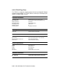
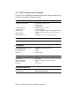
Conventions
The following conventions are used in this manual:
Convention
Meaning
Return
A key name is shown enclosed to indicate that you press a named
key on the keyboard.
Ctrl/x
A sequence such as Ctrl/x indicates that you must hold down the
key labeled Ctrl while you press another key.
BOLD
This bold type indicates user input. For example:
>>> BOOT MUAO
This line shows that the user must enter BOOT MUAO at the
console prompt.
NOTE
Notes provide general information about the current topic.
CAUTION
Cautions provide information to prevent damage to equipment
or software. Read these carefully.
WARNING
Warnings provide information to prevent personal injury. Read
these carefully.
vii
Chapter 1
Base System Description
This chapter describes the VAX 4000 Model 300 base system, including the
following:
•
Power-up self-tests
•
Digital Storage Systems Interconnect (DSSI) architecture
•
Specifications for the KA670–AA/–BA CPU and MS670–BA and –CA
memory
1.1 System Overview
All VAX 4000 Model 300 base system components are housed in a BA440
enclosure, which contains a 12-slot backplane.
Each base system contains the following:
•
A KA670–AA/–BA (L4000–A/–B) central processing unit (CPU) module
•
From one to four MS670–BA or –CA memory modules.
The base system modules are located in the following BA440 card slots:
•
Any MS670 memory modules are installed in slots 1 through 4.
•
The KA670 CPU module is installed in slot 5.
The base system operates from the KA670 CPU firmware and the controls
on the console module. The firmware is described in Section 1.2. Base
system operation also integrates Digital Storage Systems Interconnect
(DSSI) technology, which is discussed in Section 1.5.
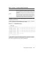
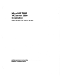
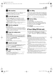
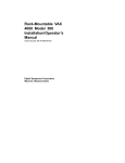
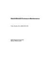
Figure 1–1 is a block diagram of the VAX 4000 Model 300 system.
Base System Description
1–1
Figure 1–1: VAX 4000 Model 300 Block Diagram
Real-Time
Devices
Main
Memory
Q22-bus
Memory
Interconnect
Ethernet
CPU
Module
Communication
Devices
DSSI
Bus
Tape Drive
Controller
Tape Drive
Disk
Console
DSSI
Bus
Disk
Disk
Disk
Disk
Disk
Disk
Disk
Disk
Disk
Disk
Disk
Disk
Disk
MLO-003829
1–2 VAX 4000 Model 300 Technical Information
1.2 Firmware Overview
Two electrically programmable read-only memory (EPROM) chips on the
KA670 CPU module contain the firmware. This firmware consists of the
following three major programs, which perform the system power-up selftests and diagnostics:
•
A console program
•
A set of self-tests for the CPU and memory
•
A primary bootstrap program (VMB)
The console program receives control whenever the processor halts. In
a processor halt, processor control passes to the console program and
instruction execution continues. The standard VAX console functionality
is emulated whenever you execute a program in ROM.
Control passes to the firmware under any of the following conditions:
•
You turn on the system.
•
You press the Restart button.
•
You assert the Q22-bus BHALT signal by pressing the Halt button.
•
You enter a break when the Break Enable/Disable switch is set to
enable.
•
A HALT instruction is executed.
•
A system error occurs.
Base System Description
1–3
1.3 Power-Up
At power-up, the console program determines the console device type and
console language, then runs the self-tests for the CPU and memory. You
choose the console language when you perform the set-up operations during
your console terminal installation procedure.
You determine the type of power-up mode by setting the Power-Up Mode
switch on the CPU console module. See your VAX 4000 Dual-Host Systems
manual for the following power-up information:
•
Power-up procedures
•
Power-Up Mode and Break Enable/Disable switch settings
•
Examples of successful power-up sequences
•
Boot and autoboot procedures
See the VAX 4000 Troubleshooting and Diagnostics manual for examples of
problems you may encounter during power-up.
1.4 Console I/O Mode Overview
If you set the Break Enable/Disable switch on the console module to enable,
the console program enters Console I/O mode after the power-up self-tests
are completed successfully. The console program also enters Console I/O
mode in response to any external halt condition.
CAUTION: Do not press the Restart button while the console program is
in console mode. Doing so destroys the system state and prevents normal
operation.
Console I/O mode allows you to control the system by typing commands
at the console prompt (>>>). You may enter these commands in either
uppercase or lowercase letters. Enter each command, then press Return .
1.4.1 Control Characters in Console I/O Mode
Table 1–1 lists the keypad control characters that have special meaning in
Console I/O mode.
1–4 VAX 4000 Model 300 Technical Information
Table 1–1: Console I/O Mode Control Characters
Character
Return
X
Action
also <CR>
(rubout)
The carriage return ends a command line. No action is taken on
a command until after it is terminated by a carriage return. A
null line terminated by a carriage return is treated as a valid, null
command. No action is taken, and the console prompts for input.
Carriage return is echoed as carriage return, line feed (<CR><LF>).
When you press x (rubout), the console deletes the previously typed
character. The resulting display differs, depending on whether the
console is a video or a hardcopy terminal.
For hardcopy terminals, the console echoes a backslash (\ )
followed by the character being deleted. If you press additional
rubouts, the additional deleted characters are echoed. If you type a
non-rubout character, the console echoes another backslash, followed
by the character typed. The result is to echo the characters deleted,
surrounding them with backslashes. For example:
EXAMI;E X
X
NE<CR>
The console echoes: EXAMI;E\ E;\ NE<CR>
The console sees the command line: EXAMINE<CR>
For video terminals, the previous character is erased and the
cursor is restored to its previous position.
Ctrl/A
or
F14
Ctrl/C
Ctrl/D
or
Ctrl/E
!
or
, , or
Ctrl/H , X (rubout), or
Ctrl/F
Ctrl/B
F12
Ctrl/O
Ctrl/Q
"
#
The console does not delete characters past the beginning of a
command line. If you press more rubouts than there are characters
on the line, the extra rubouts are ignored. A rubout entered on a
blank line is ignored.
Toggles insertion/overstrike mode for command line editing. By
default, the console powers up to overstrike mode.
Echoes ^C<CR> and aborts processing of a command. Has no effect
as part of a binary load data stream. Clears Ctrl/S and reenables
output stopped by Ctrl/O .
Moves the cursor one position to the left.
Moves the cursor to the end of the line.
Moves the cursor one position to the right.
Recalls the previous commands.
Deletes the previously typed character. Same function as X
(rubout), above.
Ignores transmissions to the console until you enter Ctrl/O . Echoes
^O when disabling output, which is not echoed when it reenables
output. Output is reenabled if the console prints an error message,
or if it prompts for a command from the terminal. Output is also
enabled by entering Maintenance mode: press Break or enter Ctrl/C .
Resumes output to the console terminal. Not echoed.
Base System Description
1–5
Table 1–1 (Cont.): Console I/O Mode Control Characters
Character
Ctrl/R
Ctrl/S
Ctrl/U
Action
Echoes <CR><LF>, followed by the current command line. Can be
used to improve the readability of a command line that has been
heavily edited.
Stops output to the console terminal until you enter Ctrl/Q . Not
echoed.
Echoes ^U<CR>. Entered, but otherwise ignored if typed on an
empty line.
The console accepts Console I/O mode commands up to 80 characters long.
Longer commands produce error messages. The character count does not
include rubouts, rubbed-out characters, or the <CR> at the end of the
command.
Two or more consecutive spaces and tabs are treated as a single space.
Leading and trailing spaces and tabs are ignored. You can place command
qualifiers after the command keyword or after any symbol or number in
the command.
All numbers (addresses, data, counts) are hexadecimal, but symbolic
register names contain decimal register numbers. The hexadecimal digits
are 0 through 9 and A through F. You can use uppercase and lowercase
letters in hexadecimal numbers (A through F) and commands.
The following symbols are qualifier and argument conventions:
[ ] = an optional qualifier or argument
{} = a required qualifier or argument
1.4.2 Console I/O Mode Commands
Table 1–2 lists and describes the Console I/O mode commands. You can
display the list of commands by entering HELP at the console prompt (>>>).
For a complete explanation of how to use the commands, along with
information on qualifiers and arguments, refer to the KA670 CPU Technical
Manual (EK–KA670–TM).
1–6 VAX 4000 Model 300 Technical Information
Table 1–2: Console I/O Mode Commands
Command
Action
BOOT
CONFIGURE
Initializes the processor and transfers execution to the VMB.
Invokes an interactive mode that permits you to enter Q22-bus
device names, then generates a table of Q22-bus I/O page device
CSR addresses and interrupt vectors.
Causes the processor to begin instruction execution at the address
currently contained in the program counter (PC). Does not perform
a processor initialization.
Deposits data into the address you specify. If you do not specify
an address space or data size qualifier, the console uses the last
address space and data size used in a DEPOSIT, EXAMINE,
MOVE, or SEARCH command.
Examines the contents of the memory location or register of the
address you specify. If you do not specify an address, + is assumed.
Searches main memory starting at address 0 (zero) for a pagealigned 128-Kbyte segment of good memory, or a restart parameter
block (RPB).
The HALT command has no effect. It is included for compatibility
with other VAX consoles.
Displays the correct syntax for all console commands.
Performs a processor initialization.
Copies the block of memory starting at the source address to a
block beginning at the destination address.
Executes the number of macro instructions you specify. If you do
not specify a number, 1 (one) is assumed.
Repeatedly displays and executes the command you specify. Press
Ctrl/C to stop the command. You can specify any valid console
command except the REPEAT command.
Finds all occurrences of a pattern and reports the addresses where
the pattern was found. If you include the /NOT qualifier, the
command reports all addresses for which the pattern did not
match.
Sets the default R5 boot flags. The value must be a hexadecimal
number of up to eight digits.
Sets the default boot device. The value must be a valid device
name.
Sets Control-P as the console halt condition, instead of a BREAK.
Connects to the DUP or MAINTENANCE driver on the node or
device you specify.
Sets the console language and keyboard type.
Sets the halt action you define. Acceptable values are the following
keywords: default, restart, reboot, halt, restart_reboot, or a
number in the range 0 to 4 inclusive.
Sets command recall state to either ENABLED (1) or DISABLED
(0).
CONTINUE
DEPOSIT
EXAMINE
FIND
HALT
HELP
INITIALIZE
MOVE
NEXT
REPEAT
SEARCH
SET BFLAG
SET BOOT
SET CONTROLP
SET HOST
SET LANGUAGE
SET HALT
SET RECALL
Base System Description
1–7
Table 1–2 (Cont.): Console I/O Mode Commands
Command
Action
SHOW BFLAG
SHOW BOOT
SHOW CONTROLP
Displays the default R5 boot flags.
Displays the default boot device.
Shows the current state of Control-P halt recognition, either
ENABLED or DISABLED.
Displays all devices displayed by the SHOW DSSI, SHOW
ETHERNET, and SHOW UQSSP commands.
Displays the status of all nodes that can be found on the DSSI
bus. For each node on the DSSI bus, the firmware displays the
node number, the node name, and the boot name and type of the
device, if available. Does not indicate whether the device contains
a bootable image.
Displays the hardware Ethernet address for all Ethernet adapters
that can be found, both on-board and on the Q22-bus.
Displays console language and keyboard type.
Displays main memory configuration, board by board.
Displays all Q22-bus I/O addresses that respond to an aligned
word read, plus vector and device name information. For each
address, the console displays the address in the VAX I/O space in
hexadecimal, the address as it would appear in the Q22-bus I/O
space in octal, and the word that was read in hexadecimal. Also
displays the vector that you should set up, and device name or
names that could be associated with the CSR.
Displays the current state of command recall, either ENABLED or
DISABLED.
Displays the halt action. Keywords include: default, restart,
reboot, halt, restart_reboot or a number in the range 0 to 4
inclusive.
Displays all RL01 and RL02 disks that appear on the Q22-bus.
Shows any SCSI devices in the system.
Shows any virtual addresses that map to the specified physical
address.
Displays the status of all disks and tapes that can be found on the
Q22-bus that support the UQSSP protocol. For each such disk or
tape on the Q22-bus, the firmware displays the controller number,
the controller CSR address, and the boot name and type of each
device connected to the controller. The command does not indicate
whether the device contains a bootable image.
Displays the current firmware version.
Starts instruction execution at the address you specify. If you
do not give an address, the current program counter is used. If
memory mapping is enabled, macro instructions are executed from
virtual memory, and the address is treated as a virtual address.
Equivalent to a DEPOSIT to PC, followed by a CONTINUE. Does
not perform a processor initialization.
SHOW DEVICE
SHOW DSSI
SHOW ETHERNET
SHOW LANGUAGE
SHOW MEMORY
SHOW QBUS
SHOW RECALL
SHOW HALT
SHOW RLV12
SHOW SCSI
SHOW TRANSLATION
SHOW UQSSP
SHOW VERSION
START
1–8 VAX 4000 Model 300 Technical Information
Table 1–2 (Cont.): Console I/O Mode Commands
Command
Action
TEST
Invokes a diagnostic test program specified by the test number
you enter. If you enter a test number of 0 (zero), all tests allowed
to be executed from the console terminal are executed. The
console accepts an optional list of up to five additional hexadecimal
arguments.
Performs an I/O bus reset, by writing a 1 (one) to IPR 55 (decimal).
Loads or unloads (that is, writes to memory or reads from memory)
the specified number of data bytes through the console serial line
(regardless of console type), starting at the specified address. For
use by automatic systems communicating with the console.
UNJAM
X
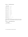
Examples 1–1 through 1–6 show sample displays for the commonly used
commands SHOW and SET.
The SET command sets the parameter to the value you specify. The SHOW
command displays the console parameter you specify.
Example 1–1: SHOW QBUS Display
>>> SHOW QBUS
Scan of Qbus I/O Space
-200000DC (760334) = 0000
-200000DE (760336) = 0AA0
-200000E0 (760340) = 0000
-200000E2 (760342) = 0AA0
-200000E4 (760344) = 0000
-200000E6 (760346) = 0AA0
-20001468 (772150) = 0000
-2000146A (772152) = 0AA0
-20001F40 (777500) = 0020
(300) RQDX3/KDA50/RRD50/RQC25/KFQSA-DISK
(304) RQDX3/KDA50/RRD50/RQC25/KFQSA-DISK
(310) RQDX3/KDA50/RRD50/RQC25/KFQSA-DISK
(154) RQDX3/KDA50/RRD50/RQC25/KFQSA-DISK
(004) IPCR
Scan of Qbus Memory Space
>>>
For each address, the console displays the address in the VAX I/O space in
hexadecimal, the address as it would appear in the Q22-bus I/O space in
octal, and the word data that was read in hexadecimal.
Base System Description
1–9
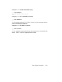
Example 1–2: SHOW DEVICE Display
>>>SHOW DEVICE
DSSI Bus 0 Node
-DIA10 (RF71)
DSSI Bus 0 Node
-DIA11 (RF71)
DSSI Bus 0 Node
-DIA12 (RF71)
DSSI Bus 0 Node
0 (BARNEY)
1 (BETTY)
2 (FRED)
7 (*)
DSSI Bus 1 Node 0 (SNEEZY)
-DIB0 (RF71)
DSSI Bus 1 Node 1 (DOPEY)
-DIB1 (RF71)
DSSI Bus 1 Node 2 (SLEEPY)
-DIB2 (RF71)
DSSI Bus 1 Node 3 (GRUMPY)
-DIB3 (RF71)
DSSI Bus 1 Node 4 (BASHFUL)
-DIB4 (RF71)
DSSI Bus 1 Node 5 (HAPPY)
-DIB5 (RF71)
DSSI Bus 1 Node 6 (DOC)
-DIB6 (RF71)
DSSI Bus 1 Node 7 (*)
UQSSP Tape Controller 0 (774500)
-MUA0 (TK70)
Ethernet Adapter
-EZA0 (08-00-2B-06-10-42)
For each device, the console displays the controller, the node, and the
address on the first line, and the device name and option on the second
line.
Example 1–3: SHOW ETHERNET Display
>>> SHOW ETHERNET
Ethernet Adapter
-EZA0 (08-00-2B-0B-29-14)
1–10 VAX 4000 Model 300 Technical Information
Example 1–4: SHOW LANGUAGE Display
>>> SHOW LANGUAGE
English (United States/Canada)
>>>
Example 1–5: SET LANGUAGE Command
>>> SET LANGUAGE 5
>>>
In this example, selection 5 is English, chosen from the language selection
menu that displays at power-up.
Example 1–6: SET BOOT Command
>>> SET BOOT MUA0
>>>
In this example, entering MUA0 sets the tape drive as the default boot
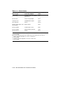
device. Table 1–3 lists all supported device names.
Base System Description
1–11
Table 1–3: Device Names
Device Logical
Name
Device Type
Controller/Adapter
RF-series ISE
Embedded DSSI host adapter
(part of CPU)
DImn1
RF-series ISE
KFQSA storage adapter
DUcn2
TF85 tape drive
Embedded DSSI adapter
MImu1
TK70 tape drive
TQK70
MUcn3
PROM (programmable read
only memory)
MRV11 module
PRAn
Ethernet adapter
On-board (part of CPU)
EZA0
Ethernet adapter
DESQA Ethernet controller
XQAn
RA-series drives
KDA50
DUcn2
1m
= DSSI bus adapter (A = first bus (0), B = second bus (1), etc.)
n = unit number
When under operating system control, DIBn devices are recognized as DIAn devices.
2 c = MSCP controller designator (A = first, B = second, etc.)
n = unit number
3 c = TMSCP controller designator (A = first, B = second, etc.)
n = unit number
1–12 VAX 4000 Model 300 Technical Information
1.5 Digital Storage Systems Interconnect (DSSI)
The KA670 CPU module contains two DSSI bus interfaces that are
dedicated to the mass storage devices in the VAX 4000 Model 300 system.
Each DSSI bus interface connects to a DSSI integrated storage element
(ISE). An ISE is a 5.25-inch integrated storage element that is housed
in a special mounting bracket for simplified enclosure installation and
upgrading.
Each DSSI bus has the following characteristics:
•
A 4-Mbytes-per-second bandwidth
•
Up to eight nodes (one interface and up to seven ISEs)
•
Eight data lines
•
One parity line
•
Eight control lines
DSSI architecture improves system performance as follows:
•
The DSSI bus handles all mass storage transactions.
•
Mass storage devices can act independently, since each device contains
its own controller. Several devices can work simultaneously.
The two DSSI bus interfaces support up to 16 nodes. These 16 nodes include
the 2 DSSI interfaces and 14 ISEs.
An ISE can maintain connections to more than one DSSI interface. In a
dual-host configuration in which multiple CPUs can be connected to the
DSSI bus interfaces, two VAX 4000 Model 300 systems have access to each
ISE on the DSSI busses.
For more information about dual hosting VAX 4000 Model 300 systems
and the advantages of such configurations, see the section on dual-host
capability in the VAX 4000 Model 300 Operation manual.
Base System Description
1–13
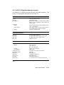
1.6 KA670–AA/BA CPU Specifications
The VAX 4000 Model 300 system uses the KA670–AA central processing
unit.
The VAXserver 4000 Model 300 uses the KA670–BA central
processing unit.
Central Processing Unit
Addressing modes
Clock rate
Data path width
Number of data types
Number of instructions
General purpose registers
PDP–11 compatibility mode
Time bases
I/O bus interface
Backplane termination
General register: 8
143 MHz
64 bits
Hardware: 9
Software emulated: 7
Hardware: 272
Software emulated: 32
16 (32-bit wide)
Program counter: 4
Index: 9
Emulated in software
Time-of-year clock: 1 (battery backup)
Interval timer: 1 (10 milliseconds)
Programmable timers: 2
One Q22-bus interface with 8192 entry map
240 Memory Management and Control
Page size
Virtual address space
Physical memory space
Number of memory modules
512 bytes
4 gigabytes
512 Mbytes
4 maximum
Performance
Instruction prefetch buffer size
On-chip cache
Size
Speed
Associativity
On-board cache
Size
Speed
12 bytes
2 Kbyte
28 nanoseconds
Direct mapped
128 Kbytes
84 nanoseconds
1–14 VAX 4000 Model 300 Technical Information
Performance
Associativity
Translation buffer
Size
Associativity
Q22-bus address translation
map cache
Size
Associativity
I/O bus buffer size
Input
Output
Maximum I/O bandwidth
Block mode DMA read
Block mode DMA write
Direct mapped
64 entry
Fully associative
16 entry
Fully associative
32 bytes
4 bytes
2.4 Mbytes/second
3.3 Mbytes/second
Ethernet Port
Supported protocols
Supported media types
Data path width
Maximum bandwidth
Buffer size
Transmit buffer
Receiver buffer
Ethernet V2.0
Standard or ThinWire
1 bit
10 Mbits/second
128 bytes/second
128 bytes/second
Digital Storage Systems Interconnect (DSSI) Connector
Maximum number of supported devices
Data path width
Maximum bandwidth
Maximum queue I/O
Buffer size
Transmit buffer
Receiver buffer
14
8 bits
4 Mbytes/second
800/second
128 bytes/second
128 bytes/second
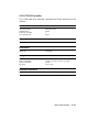
Console Serial Line
Interface standards
EIA RS–423–A/CCITT V.10 X.26
EIA RS–232–C/CCITT V.28
DEC–423
Base System Description
1–15
Console Serial Line
Data format
Baud rates
1 start bit, 8 data bits, 0 parity bits, 1 stop
bit
300; 600; 1200; 2400; 4800; 9600; 19,200;
38,400
Ordering Information
Included as part of base system
Configuration Information
Form factor
Power requirements
Power consumption
Bus loads
Quad height
+5 Vdc, 7.4 A; +3.3 Vdc, 0.27 A
+12 Vdc, 0.35 A; –12 Vdc, 0.04 A
42.6 W
4.0 ac; 1.0 dc
Operating System Support
VMS
VAXELN
Version 5.3–2 and later
Diagnostic Support
MicroVAX Diagnostic Monitor
Self-tests
Release 131 and later
Yes
Related Documentation
EK–KA670–TM
EK–347AB–MG
KA670 CPU Technical Manual
KA670 CPU System Maintenance
1–16 VAX 4000 Model 300 Technical Information
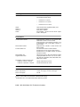
1.7 MS670–BA and –CA Memory Specifications
The MS670–BA is a 32-Mbyte memory module that provides memory
expansion for the KA670–AA/–BA CPU module. The MS670–CA is a
64-Mbyte memory module. The MS670 modules interface with the CPU
through the MS670 local memory interconnect.
You can use up to four MS670 modules in the VAX 4000 Model 300 system.
Operating system support and diagnostic support are the same as for the
KA670 CPU module, as listed in Section 1.6.
Performance
Memory Cycle Time at 28 nanoseconds:
Memory Read (Octaword):
Page mode memory read
Non-page mode memory read
Memory write (Octaword):
Page mode memory write
Non-page mode memory write
Memory masked write (Longword):
Page mode memory write
Non-page mode memory write
392 nanoseconds
756 nanoseconds
308 nanoseconds
504 nanoseconds
399 nanoseconds
504 nanoseconds
Ordering Information
MS670–BA
MS670–CA
32-Mbyte field-installed kit
64-Mbyte field-installed kit
Configuration Information
Form factor
Power requirements
Power consumption
Bus loads
Quad height
+5 Vdc, 2.52 A; +12 Vdc, 0.0 A
12.6 W
0.0 ac; 0.0 dc
Base System Description
1–17
Chapter 2
Option Specifications
This chapter lists specifications for the options currently supported in the
VAX 4000 Model 300 system, grouped as follows:
•
Mass storage
•
Communications
•
Real-time
•
Printer
•
Graphics
The specifications appear in alphanumerical order within each of the above
groups. All weights are approximate.
Some of the options are already installed in your system. If you want to
add other options, your Digital sales representative can advise you.
Option Specifications
2–1
2.1 Options Overview
The option specifications include the following, where applicable:
•
Functional information
•
Ordering information
•
Performance
•
Configuration information
•
Related documentation
Unless otherwise noted, operating system support and diagnostic support
for all options are the same as for the KA670 CPU module, as listed in
Section 1.6.
2.1.1 Configuration
Options must be properly configured so that the system recognizes them.
Each option in a system has a device address, commonly referred to as
a control and status register (CSR) address, and an interrupt vector that
must be set when the option is installed. Options are usually configured by
setting switches or jumpers on modules already configured at the factory
or Digital service representatives configure the option when they install it
in your system.
Self-maintenance customers can find information on setting CSR addresses
and interrupt vectors in the Microsystems Options volume of the Entry
Systems Service kit.
2–2 VAX 4000 Model 300 Technical Information
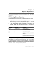
2.2 Mass Storage Options
The VAX 4000 Model 300 system supports the following mass storage
devices:
•
Internal to the BA440 enclosure:
TK-series tape drive
TF-series tape drive
TLZ-series tape
RF-series integrated storage element (ISE)
•
External to the BA440 enclosure:
RRD-series compact disk subsystem (tabletop)
TU81–Plus tape
TSV-series tape
TLZ-series tape
RA-series disks
Four RA-series drives are supported by one KDA50 controller. The system
supports up to eight RF-series drives with embedded and/or KFQSA
controllers. You can put only two disk controllers in the Q-bus backplane,
two KDA50s, two KFQSAs, or one of each.
Up to four RF-series ISEs can be installed in your system.
The
CPU communicates with the ISEs through a Digital Storage Systems
Interconnect (DSSI) adapter, which is built into the CPU. Your VAX 4000
system has two DSSI adapters, and hence, two separate DSSI busses. Each
DSSI bus is capable of supporting seven integrated storage elements.
Option Specifications
2–3
2.2.1 KDA50 Controller
The KDA50 is an intelligent controller that interfaces with up to four SDIcompatible mass storage devices on the Q22-bus.
Functional Information
Controller protocol
Bad block replacement
Supported drives
Drives per controller
Controllers per system
Drive interconnect
MSCP
Software dependent
RA60, RA70, RA81, RA82, RA90
4
1 maximum for VMS 5.1
2 maximum for VMS V5.2 and later
Transformer-coupled radial
Ordering Information
KDA50–SF
KDA50–SG
RA-series disk drive controller, controls up to a
maximum of four RA-series devices1
Second KDA50 controller, for support of up to four
RA-series devices, uses three Q-bus slots 1
Performance
Read/Write data transfers
Data buffering
Command buffering
Up to 16-byte block mode DMA
32 Kbytes
20 command and response ring buffers
Configuration Information
Form factor
Power requirements
Power consumption
Bus loads
Two quad height
+5 Vdc, 13.5 A (typ); +12 Vdc, 0.03 A (typ)
67.86 W
3.0 ac; 0.5 dc
Related Documentation
EK–KDA5Q–UG
1 Field
KDA50–Q User’s Guide
installed option.
2–4 VAX 4000 Model 300 Technical Information
2.2.2 KFQSA Storage Adapter
The KFQSA is an intelligent storage adapter that allows Q22-bus systems
to communicate with storage peripherals based on the Digital Storage
System Interconnect (DSSI).
Functional Information
Controller protocol
Supported drive
Drives per adapter
Drive interconnect
Controllers per system
SSP: to and from Q22-bus host
DSSI: to and from ISEs
RF-series ISEs
7
Direct
2 maximum
Ordering Information
KFQSA–SG
RF-series ISE adapter, controls up to a maximum
of 7 RF-series ISEs
Performance
Peak transfer rate
Sustained transfer rate
I/O request throughput
Error detection
4 Mbytes/second
1.5 Mbytes/second
190 I/O requests/second (single-sector reads)
DSSI bus parity and check character,
transmissions
all
Configuration Information
Form factor
Power requirements
Power consumption
Bus loads
Quad height
+5 Vdc, 5.5 A (typ)
27.5 W
4.4 ac; 0.5 dc
Related Documentation
EK–KFQSA–IN
KFQ Storage Adapter Installation and User
Manual
Option Specifications
2–5
2.2.3 KLESI Controller
The KLESI–SA is a controller that interfaces with the TU81–Plus tape
drive on the Q22-bus.
Functional Information
Controller protocol
Supported drive
Drives per adapter
Drive interconnect
Controllers per system
TMSCP
TU81–Plus
1
Direct
1 maximum
Ordering Information
Included with the TU81–Plus tape drive
Configuration Information
Form factor
Power requirements
Power consumption
Bus loads
Dual
+5 Vdc, 4.0 A (typ); +12 Vdc, 0.0 A (typ)
20.0 W
0.5 ac; 1.0 dc
Related Documentation
EK–LESIB–UG
KLESI–B Module User’s and Installation Guide
2–6 VAX 4000 Model 300 Technical Information
2.2.4 KZQSA Storage Adapter
The KZQSA storage adapter controls the TLZ04 and RRD-series devices on
the Q22-bus.
Functional Information
Adapter protocol
Supported drive
Controllers per system
TMSCP
TLZ04; two external cables or two devices
2
Ordering Information
KZQSA–SA
KZQSA–SF
Factory-installed
Field-installed
Performance Information
Peak transfer rate
Error detection
4 Mbytes synchronous
Q-bus parity
Configuration Information
Form factor
Power requirements
Power consumption
Bus loads
Quad height
+5 Vdc, 5.5 A (typ); +12 Vdc, 0.0 A (typ)
27.5 W
4.4 ac; 1.0 dc
Related Documentation
EK–KZQSA–IN
KZQSA Storage Adapter Installation and User
Manual
Option Specifications
2–7
2.2.5 RA60 Disk Drive
The RA60 disk drive is a high-capacity removable disk drive that provides
205 Mbytes of formatted storage space. The VAX 4000 Model 300 supports
these drives in separate storage expansion enclosures only.
Storage Capacity
User capacity
User capacity (blocks)
205 Mbytes
400,176
Ordering Information
RA60–AF
BC26V–06
RA60 disk drive and cables
Interconnect cable with connector block
Performance
Average seek time
Average rotational latency
Average access time
Peak transfer rate
41.67 milliseconds
8.33 milliseconds
50.30 milliseconds
15.84 Mbits/second
Physical Specifications
Height
Width
Depth
Weight
26.52
48.26
85.09
68.95
cm (10.44 in)
cm (19 in)
cm (33.75 in)
kg (152 lb)
Configuration Information
Form factor
10.5-in high, full rack width
Related Documentation
EK–ORA60–UG
RA60 Disk Drive User’s Guide
2–8 VAX 4000 Model 300 Technical Information
2.2.6 RA70E Disk Drive
The RA70E disk drive is a high-capacity fixed-disk drive that provides 280
Mbytes of formatted storage space. The VAX 4000 Model 300 supports these
drives in separate storage expansion enclosures only.
Storage Capacity
User capacity
280 Mbytes
Ordering Information
RA70E–SA
RA70E–SF
RA70E disk drive, factory installed
RA70E disk drive, field installed
Performance
Average seek time
Average rotational latency
Average access time
Peak transfer rate
19.5 milliseconds
7.5 milliseconds
27.0 milliseconds
1.4 Mbytes/second
Physical Specifications
Height
Width
Depth
Weight
Form factor
26.3 cm (10.38 in)
44.5 cm (17.5 in)
67.3 cm (26.5 in)
61.2 kg (135 lb)
5.25-in high, full rack width
Related Documentation
EK–ORA70–SV
EK–ORA70–PS
RA70 Disk Drive Service Manual
RA70 Disk Drive Pocket Reference
Option Specifications
2–9
2.2.7 RA81 Disk Drive
The RA81 disk drive is a high-capacity fixed-disk drive that provides 456
Mbytes of formatted storage space. The VAX 4000 Model 300 supports these
drives in separate storage expansion enclosures only.
Storage Capacity
User capacity
User capacity (blocks)
456 Mbytes
891,070
Ordering Information
RA81–HA/–HD
RQA81–AA
RQA81–AD
BC26V–6D
RA81 disk drive (120 V/240 V)
RA81 disk drive (120 V) with KDA50 controller
and BC26V–06 cable
RA81 disk drive (240 V) with KDA50 controller
and BC26V–6D cable
Interconnect cable with connector block
Performance
Average seek time
Average rotational latency
Average access time
Peak transfer rate
28.00 milliseconds
8.32 milliseconds
36.30 milliseconds
17.4 Mbits/second
Physical Specifications
Height
Width
Depth
Form factor
Weight
26.3 cm (10.38 in)
44.5 cm (17.5 in)
67.3 cm (26.5 in)
10.5-in high, full rack width
61.2 kg (135 lb)
Related Documentation
EK–ORA81–SV
EK–ORA81–UG
RA81 Disk Drive Service Guide
RA81 Disk Drive User’s Guide
2–10 VAX 4000 Model 300 Technical Information
2.2.8 RA82 Disk Drive
The RA82 disk drive is a high-capacity fixed-disk drive that provides 623
Mbytes of formatted storage space. The VAX 4000 Model 300 supports these
drives in separate storage expansion enclosures only.
Storage Capacity
User capacity
User capacity (blocks)
623 Mbytes
1,216,660
Ordering Information
RA82–AA
RA82–AD
BC26V–06
RA82 disk drive (120 V) with one BC26V–12 cable
RA82 disk drive (240 V) with one BC26V–12 cable
Interconnect cable with connector block
Performance
Average seek time
Average rotational latency
Average access time
Peak transfer rate
24.00 milliseconds
8.33 milliseconds
32.33 milliseconds
19.2 Mbits/second
Physical Specifications
Height
Width
Depth
Weight
26.3
44.5
67.3
61.2
cm (10.38 in)
cm (17.5 in)
cm (26.5 in)
kg (135 lb)
Configuration Information
Form factor
10.5-in high, full rack width
Related Documentation
EK–ORA82–SV
EK–ORA82–UG
RA82 Disk Drive Service Guide
RA82 Disk Drive User’s Guide
Option Specifications
2–11
2.2.9 RA90 Disk Drive
The RA90 disk drive is a high-capacity fixed-disk drive that provides 1.2
gigabytes of formatted storage space. The VAX 4000 Model 300 supports
these drives in separate storage expansion enclosures only.
Storage Capacity
User capacity
User capacity (blocks)
1.2 gigabytes
2,376,153
Ordering Information
RA90–NA
RA90–ND
BC26V–12
RA90 disk drive (120 V)
RA90 disk drive (240 V)
Interconnect cable with connector block
Performance
Average seek time
Average access time
Peak transfer rate
18.5 milliseconds
8.33 milliseconds
22.2 Mbits/second
Physical Specifications
Height
Width
Depth
Weight
26.6
23.0
68.5
13.6
cm (10.4 in)
cm (8.7 in)
cm (27.0 in)
kg (62 lb)
Configuration Information
Form factor
Power requirements
Power consumption
10.5-in high, full rack width
+5 Vdc, 1.3 A; +12 Vdc, 2.21 A
18.7 W
Related Documentation
EK–ORA90–SV
EK–ORA90–UG
RA90 Disk Drive Service Guide
RA90 Disk Drive User’s Guide
2–12 VAX 4000 Model 300 Technical Information
2.2.10 RA92 Disk Drive
The RA92 disk drive provides 1.5 Gbytes of formatted storage space. The
VAX 4000 Model 300 supports the RA92 only in separate storage expansion
enclosures.
Storage Capacity
User capacity
User capacity (blocks)
1.5 gigabytes
2,940,952
Ordering Information
RA92–CA/CD
BC26J–xx
BC27V–xx
RA92 disk drive (120 V @ 60 Hz; 240 V @ 50 Hz)
12-, 25-, 50, or 80-ft. interconnect cable
12-, 15-, 25-, 35-, 50-, or 80-ft. interconnect cable
Performance
Average seek time
Single track seek
Peak transfer rate
16.5 milliseconds
3.0 milliseconds
22.2 Mbits/second
Physical Specifications
Height
Width
Depth
Weight
26.6 cm (10.42 in)
23.0 cm (8.75 in)
60.96 cm (24.0 in)
31.8 kg (70 lb)
Configuration Information
Form factor
Power requirements
Power consumption
10.5-in high
+5 Vdc, 1.3 A; +12 Vdc, 2.21 A
18.7 W
Related Documentation
EK–ORA92–UG–02
RA90/RA92 User’s Guide
Option Specifications
2–13
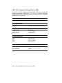
2.2.11 RF31 Integrated Storage Element (ISE)
The RF31 is a DSSI integrated storage element (ISE) that provides 381
Mbytes of formatted storage space. An ISE is a 5.25-inch integrated
storage element that is housed in a special mounting bracket for simplified
installation and upgrading.
Storage Capacity
Data storage capacity
381 Mbytes, formatted
Ordering Information
RF31E–AF
381 Mbyte half-height ISE, field-installed
Performance
Average seek time
Average access time
Peak transfer rate
14.7 milliseconds
23 milliseconds
4.0 Mbytes/second
Physical Specifications
Height
Width
Depth
Weight
4.40 cm (1.75 in)
14.60 cm (5.75 in)
20.45 cm (8.25 in)
1.81 kg (4.0 lb)
Configuration Information
Form factor
Power requirements
Power consumption
Standard 5.25-in footprint
+5 Vdc, 1.0 A; +12 Vdc, 2.80 A
38.6 W
2–14 VAX 4000 Model 300 Technical Information
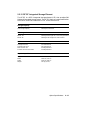
2.2.12 RF31F Integrated Storage Element
The RF31F is a DSSI integrated storage element (ISE) that provides 200
Mbytes of formatted storage space. The RF31F features a code modification
to the UVE ROM that makes the RF31F a half-stroke drive.
Storage Capacity
Data storage capacity
200 Mbytes, formatted
Ordering Information
RF31F–EA
RF31F–AF
200-Mbyte half-height ISE, no mounting hardware
200-Mbyte half-height ISE, field-installed
Performance
Average seek time
Average access time
Peak transfer rate
Transfer rate from the media
12.3 milliseconds
20.6 milliseconds
4.0 Mbytes/second
2.0 Mbytes/second
Physical Specifications
Height
Width
Depth
Weight
4.40 cm (1.75 in)
14.60 cm (5.75 in)
20.45 cm (8.25 in)
1.81 kg (4.0 lb)
Option Specifications
2–15
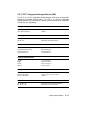
Configuration Information
Form factor
Data surfaces
Bits per inch
Tracks per inch
Power requirements
Power consumption
Standard 5.25-in footprint
8
30,064
1,875
+5 Vdc, 1.3 A; +12 Vdc, 1.1 A (seeking)
19.7 W
Related Documentation
EK–RF72D–UG
EK–RF72D–SV
RF31/RF72 User Guide
RF31/RF72 Service Guide
2–16 VAX 4000 Model 300 Technical Information
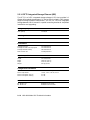
2.2.13 RF71 Integrated Storage Element (ISE)
The RF71 is a DSSI integrated storage element (ISE) that provides 400
Mbytes of formatted storage space. An ISE is a 5.25-inch integrated
storage element that is housed in a special mounting bracket for simplified
installation and upgrading.
Storage Capacity
User capacity
User capacity (blocks)
400 Mbytes
781,440
Ordering Information
RF71E–AA
RF71E–AA
400 Mbyte ISE
400 Mbyte ISE, field-installed
Performance
Average random seek time
Average rotational latency
Average access time
Peak transfer rate
19.20 milliseconds
8.33 milliseconds
34.2 milliseconds
1.5 Mbits/second
Physical Specifications
Height
Width
Depth
Weight
7.75 cm (3.05 in)
14.60 cm (5.75 in)
20.75 cm (8.17 in)
4.09 kg (9.0 lb)
Configuration Information
Form factor
Power requirements
Power consumption
Standard 10.5-in footprint
+5 Vdc, 1.25 A; +12 Vdc, 1.64 A
25.93 W
Related Documentation
EK–RF71D–IM
EK–RF71D–UG
RF71 Disk Drive Installation Manual
RF71 Disk Drive User’s Guide
Option Specifications
2–17
2.2.14 RF72 Integrated Storage Element (ISE)
The RF72 is a DSSI integrated storage element (ISE) that provides 1.0
Gbytes of formatted storage space. RF-series ISEs are used in DSSI busses
(Digital Storage Systems Interconnect). An ISE is a 5.25-inch integrated
storage element that is housed in a special mounting bracket for simplified
installation and upgrading.
Storage Capacity
User capacity
1.0 Gbytes
Ordering Information
RF72E–AA
1.0 Gbyte ISE
Performance
Average seek time
Average raw seek time, high speed
Average rotational latency
Peak transfer rate
13.3 milliseconds
10.3 milliseconds
18.6 milliseconds
2.0 Mbytes/second
Physical Specifications
Height
Width
Depth
Weight
7.75 cm (3.05 in)
14.60 cm (5.75 in)
20.75 cm (8.17 in)
4.09 kg (9.0 lb)
Configuration Information
Form factor
Power requirements
Power consumption, spin-up
Power consumption, seeking
Standard 5.25-in high, full rack width
+5 Vdc, 1.25 A; +12 Vdc, 3.12 A
57.1 W
27.7 W
Related Documentation
EK–RF72D–UG
EK–RF72D–SV
RF31/RF72 User Guide
RF31/RF72 Service Guide
2–18 VAX 4000 Model 300 Technical Information
2.2.15 RRD40 Compact-Disc Subsystem
The RRD40 is a CD reader that retrieves data in fixed-length blocks from
removable compact-disc media.
Functional Information
Modes
Orientation
Idle mode
Operation mode: search, normal play
Horizontal
Ordering Information
RRD40–SF
Field-installed tabletop CDROM drive
Performance
Motor stop time
Motor start time
Formatted capacity
Average transfer rate
Average latency
Initialization time
30% of nominal speed within 30 seconds maximum, 5 seconds typical
90% of nominal speed within 20 seconds maximum, less than 11 seconds typical
525 Mbytes with maximum of 600 Mbytes
153.6 Kbytes/s, mode 1; 176.4 Kbytes/s, mode 2
60 µs max inner track; 155 µs outer track
15 seconds maximum to sector zero
Physical Specifications
Height
Width
Depth
Weight
27.6 cm (11.02 in)
8.18 cm (3.27 in)
22.7 cm (9.06 in)
5.0 kg (11.0 lb)
Configuration Information
Power consumption
19.2 W max; Play mode: 18 W max
Related Documentation
EK–RRD40–OM
EK–RRD40–SU
RRD40 Disk Drive Owner’s Manual
RRD40 MicroVAX Monitor User’s Guide Updates
Option Specifications
2–19
2.2.16 RRD42 Optical Compact-Disc Subsystem
The RRD42 is a 600-Mbyte optical CD reader that retrieves data in fixedlength blocks from removable compact-disc media.
Functional Information
Interface
SCSI-2, single-ended, asynchronous
To Q-bus systems through KZQSA storage adapter
Ordering Information
RRD42–AA
RRD42–DA
Embedded disc drive with controller
Tabletop model, with power supply
Performance
Seek time, average
Seek time, max full stroke
Rotational speed, innermost track
Rotational speed, outermost track
Start time/Stop time
Transfer rate, sustained
Transfer rate, burst
400 millisecond, (typical)
800 millisecend, (typical)
530 rpm
200 rpm
2.0 second (max)
150 Kbytes/second
1.50 Mbytes/second (max)
Physical Specifications
Height
Width
Depth
Weight
–AA
–DA
4.15 cm (1.62 in)
14.60 cm (5.75 in)
20.80 cm (8.0 in)
1.30 kg (2.8 lb)
2.9 kg (6.30 lb)
Configuration Information
Form factor
Standard 5.25-in high, full rack width
Related Documentation
EK–RRD42–OM
RRD42 Disc Drive Owner’s Manual
2–20 VAX 4000 Model 300 Technical Information
2.2.17 TF85 Tape Drive
The TF85 is a cartridge tape subsystem that can store up to 2.6 Gbytes.
The TF85 is a streaming tape drive with a built-in DSSI (Digital Storage
Systems Interconnect) controller, and can be used as a part of a DSSI
VAXcluster.
Functional Information
Recording media
Tape dimensions
Mode of operation
Recording method
Recording density
Number of tracks
Storage capacity
Transfer rate
Magnetic, metal-particle tape
1.27 cm (0.5 in) wide, 366 m (1100 ft) long
Streaming
Serpentine
42,500 bits/in
48
2.6 Gbytes, formatted
800 Kbytes/second, formatted
Ordering Information
TF85–BA
TF85E–JA
TF85–TA
TF85–TB
2.6-Gbyte cartridge tape subsystem for DSSIbased systems; includes tape drive, DSSI
controller, tape cartridge, and head cleaning
cartridge
Same as –AA but factory-installed
Same as –AA but tabletop, 120 V
Same as –AA but tabletop, 220 V
Performance
Tape start time
Tape stop time
Tape speed
Streaming data rate
Access time
TF85 mode
TK70/50 mode
Recording technique
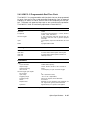
Burst rate on DSSI bus
300
300
390
800
milliseconds maximum
milliseconds maximum
cm/second (100 in/second)
Kbytes/second
3 minutes maximum
60 minutes maximum
Two-track parallel, serpentine
3.8 Mbytes/second
Option Specifications
2–21
Physical Specifications
Height
Width
Depth
Weight
8.25 cm (3.25 in)
14.60 cm (5.70 in)
21.44 cm (8.44 in)
15.4 kg (7.0 lb)
Configuration Information
Form factor
Power requirements
Power consumption
Bus loads
Half-rack, near 5.25-in footprint
+5 Vdc, 1.8 A (typ); +12 Vdc, 1.0 A (typ)
36.3 W
0.0 ac; 0.0 dc
Related Documentation
EK–OTF85–OM
EK–OTK85–RC
TF85 Cartridge Tape Subsystem Owner’s Manual
TF85 Cartridge Tape Drive Reference Card
2–22 VAX 4000 Model 300 Technical Information
2.2.18 TK50 Tape Drive
The TK50 is a streaming-tape drive subsystem that can store up to 95
Mbytes on a tape cartridge for backup data storage.
Functional Information
Recording media
Tape dimensions
Mode of operation
Recording method
Recording density
Number of tracks
Storage capacity
Magnetic tape
1.27 cm (0.5 in) wide, 182.9 m (600 ft) long
Streaming
Serpentine
6667 bits/in
22
94.5 Mbytes formatted
Ordering Information
TK50E–AF
TQK50–SF
95-Mbyte cartridge tape drive, field-installed
Controller for TK50E–AF
Performance
Tape start time
Tape speed
Streaming data rate
Access time (from insertion of tape)
300 milliseconds maximum
2925 cm (75 in)/second
62 Kbytes/second
60 minutes maximum
Physical Specifications
Height
Width
Depth
Weight
8.25 cm (3.25 in)
14.60 cm (5.70 in)
21.44 cm (8.44 in)
2.27 kg (5.0 lb)
Configuration Information
Form factor
Power requirements
Power consumption
Bus loads
Standard 5.25-in footprint
+5 Vdc, 1.5 A; +12 Vdc, 2.4 A
36.3 W
0.0 ac; 0.0 dc
Option Specifications
2–23
Related Documentation
EK–LEP05–OM
EK–OTK50–UG
TK50 Tape Drive Subsystem Owner’s
Manual
TK50 Tape Drive Subsystem Users
Guide
2–24 VAX 4000 Model 300 Technical Information
2.2.19 TK70 Tape Drive
The TK70 is a streaming-tape drive subsystem that can store up to 296
Mbytes on a tape cartridge for backup data storage. The TK70 can read
data from cartridges recorded on a TK50 drive, but cannot write data to
cartridges recorded on a TK50 drive.
Functional Information
Recording media
Tape dimensions
Mode of operation
Recording method
Recording density
Number of tracks
Storage capacity
Magnetic tape
1.27 cm (0.5 in) wide, 182.9 m (600 ft) long
Streaming
Serpentine
10,000 bits/in
48
296 Mbytes formatted
Ordering Information
TK70E–SA
TQK70–SF
296 Mbyte cartridge tape drive
Controller for TK70E–AF
Performance
Tape start time
Tape stop time
Tape speed
Streaming data rate
Access time (from insertion of tape)
325 milliseconds maximum
200 milliseconds maximum
390 cm/second (100 in/second)
125 Kbytes/second
60 minutes maximum
Physical Specifications
Height
Width
Depth
Weight
8.25 cm (3.25 in)
14.60 cm (5.70 in)
21.44 cm (8.44 in)
2.27 kg (5.0 lb)
Option Specifications
2–25
Configuration Information
Form factor
Power requirements
Power consumption
Bus loads
Standard 5.25-in footprint
+5 Vdc, 1.35 A; +12 Vdc, 2.4 A
35.6 W
0.0 ac; 0.0 dc
Related Documentation
EK–OTK70–OM
EK–OTK70–TM
EK–OTK70–SM
TK70 Tape Drive Subsystem Owner’s
Manual
TK70 Tape Drive Subsystem Technical
Manual
TK70 Tape Drive Subsystem Service
Manual
2–26 VAX 4000 Model 300 Technical Information
2.2.20 TLZ04 Tape Drive
The TLZ04 is a 1.2-Gbyte cassette (DAT) SCSI tape drive, either tabletop
or embedded in the VAX 4000 Model 300 system.
Functional Information
Recording media
Mode of operation
Storage capacity
Drive interface
Magnetic tape
Streaming and start/stop
1.2 Gbytes formatted
RDAT compatible
Ordering Information
TLZ04–JA
TLZ04–JF
TLZ04–DA
TLZ04–GA
Embedded (factory installed)BA400-series
Embedded (field installed)BA400-series
Tabletop
Tabletop including BC06P cable
Performance
Passes per cassette tape
Media
Bit density
Transfer rate (sustained)
Recording format
Read/write speed
Peak transfer rate, raw
Peak transfer rate,user data
Average file access time
Rewinding time
300
TLZ04–CA cassette tape
114 Mbits/square inch
183 Kbytes/second
Digital data storage (DDS)
0.87 cm/second
180 Kbytes/second
170 Kbytes/second
20 seconds
40 seconds
Option Specifications
2–27
Physical Specifications
Height
Width
Depth
Weight
10.0 cm (3.8 in), tabletop
8.2 cm (3.35 in), embedded
32.5 cm (12.7 in), tabletop
14.60 cm (5.70 in), embedded
28.5 cm (11.2 in), tabletop
21.44 cm (8.44 in), embedded
7.72 kg (17 lb), tabletop
2.20 kg (7.72 lb), embedded
Data Organization
Recording technology
Recording method
Recording density
Record size
Maximum capacity
Recording medium
Helical scan
Digital Data Storage (DDS)
61,000 bits/inch
Variable
1.2 Gbytes, formatted
60 m x 4 mm
Maintenance
Recommended cleaning cartridge
Every 25 hours
Configuration Information
Form factor
Power requirements
Power consumption (embedded)
Power consumption (tabletop)
5.25-inch DAT drive
90 to 132 V, 1.6 A; 198.0 to 264 V, 1.0 A
15.0 W
50.0 W
Related Documentation
EK–TLZ04–MM
EK–BA400–IN
EK–TLZ04–OM
TLZ04 Tape Drive Subsystem Service Manual
Tape Drive Subsystem Service Manual
TLZ04 Tape Drive Owner’s Manual
2–28 VAX 4000 Model 300 Technical Information
2.2.21 TQK70 Controller
The TQK70 controller module provides the interface between the TK70 tape
drive and the Q22-bus.
Functional Information
Controller protocol
Supported drive
Drives per controller
Drive interconnect
Controllers per system
TMSCP
TK70
1
Direct
1 maximum
Ordering Information
TQK70–SA
TQK70–SF
Controller for TK70E–AF
Controller for TK70E–AF, field-installed
Performance
Data throughput rate
Read/Write data transfers
Buffer size
125 Kbytes/second
Up to 16-word burst mode DMA, truncated to 8word burst mode if another device is requesting
the bus
64 Kbytes
Configuration Information
Form factor
Power requirements
Power consumption
Bus loads
Dual height
+5 Vdc, 3.5 A; +12 Vdc, 0.0 A
17.5 W
4.3 ac; 0.5 dc
Related Documentation
EK–OTK70–OM
TK70 Tape Drive Subsystem Owner’s
Manual
Option Specifications
2–29
2.2.22 TSZ07 Tape Drive
The TSZ07 is a 40-Mbyte, high-capacity, streaming, 9-track, reel-to-reel,
half-inch magnetic tape drive with dual recording densities. The TSZ07 is
available in tabletop, cabinet, or rackmount models, and cannot be mounted
inside the VAX 4000 Model 300 system.
Functional Information
Recording densities
Mode of operation
Storage capacity
Number of tracks
Drive interface
1600 bits/inch or 6250 bits/inch
Streaming and start/stop
40 Mbytes with 8-Kbyte blocks, formatted
9 on 0.5-inch magnetic tape
RDAT compatible
Ordering Information
TSZ07–AA
TSZ07–BA
TSZ07–BB
TSZ07–CA
Rackmount, specify country kit
Cabinet, 120 V
Cabinet, 240 V
Tabletop, specify country kit
Performance
Transfer rate
Load/unload time
Recording speed
Rewinding speed
4 Mbytes/second
55 seconds
100 in/second
150 seconds (with 2400 reel)
2–30 VAX 4000 Model 300 Technical Information
Physical Specifications
Tabletop
Height
Width
Depth
Weight
26.78 cm (10.50 in)
50.36 cm (19.75 in)
68.85 cm (27.00 in)
36.8 kg (81 lb)
Rackmount
Height
Width
Depth
Weight
22.32 cm (8.75 in)
43.35 cm (17.0 in)
64.03 cm (25.5 in)
31.8 kg (70 lb)
Cabinet
Height
Width
Depth
Weight
101.0
56.10
76.50
180.1
cm (40.0 in)
cm (22.0 in)
cm (30.0 in)
kg (238 lb)
Maintenance
Cleaning cartridge
Every 25 hours recommended
Configuration Information
Form factor
Power consumption
5.25-inch DAT drive
385 W, cabinet
355 W, tabletop
355 W, rackmount
Related Documentation
EK–TSZ07–IN–002
EK–TSZ07–TM–002
TSZ07 Installation/Owner’s Manual
TSZ07 Technical Manual
Option Specifications
2–31
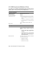
2.2.23 TSV05 Tape Drive
The TSV05 is a magnetic streaming-tape drive that provides 40.5 Mbytes
of backup data storage. The TSV05 reads or writes up to 160 Kbytes per
second in standard ANSI format.
Functional Information
Recording media
Tape dimensions
Mode of operation
Recording method
Recording density
Number of tracks
Storage capacity
Magnetic tape, 26.7 cm (10.5 in) reel
1.27 cm (0.5 in) wide, 731 m (2400 ft) long
Streaming
Phase encoded (PE)
1600 bits/in
9
40 Mbytes formatted
Ordering Information
TSV05–SB
TSV05 tape drive subsystem
Performance
Handling
Tape velocity
Maximum data transfer rate
Rewind time
Bidirectional reel-to-reel with compliance arm
64 or 254 cm/second (25 or 100 in/second)
40 or 160 Kbytes/second
2.8 minutes/731 m (2400 ft)
Physical Specifications
Height
Width
Depth
Weight
Form factor
23.0 cm (8.75 in)
43 cm (17 in)
62 cm (24.5 in)
36 kg (80 lb)
10.5-in high, full rack width
Related Documentation
EK–TSV05–UG
EK–TSV05–TM
TSV05 Tape Transport System User’s Guide
TSV05 Tape Transport Subsys Tech Manual
2–32 VAX 4000 Model 300 Technical Information
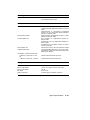
2.2.24 TSV05 Controller
The TSV05 tape drive controller interfaces the TSV05 tape drive to the
Q22-bus.
Functional Information
Controller protocol
Supported drive
Drives per controller
Drive interconnect
Controller unique
TSV05
1
Direct
Ordering Information
TSV05–SB
TSV05 tape drive subsystem
Performance
Buffer size
3.5 Kbytes
Configuration Information
Form factor
Power requirements
Power consumption
Bus loads
Quad height
+5 Vdc, 6.5 A (typ); +12 Vdc, 0.0 A (typ)
32.5 W
2.4 ac; 1.0 dc
Related Documentation
EK–TSV05–UG
TSV05 Tape Transport System User’s Guide
Option Specifications
2–33
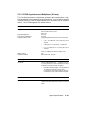
2.2.25 TU81–Plus Tape Drive
The TU81–Plus is a reel-to-reel tape drive mounted in a 101.6-cm (40in) cabinet. The drive supports two industry-standard recording methods:
group coded recording (GCR) and phase encoded (PE).
Storage Capacity
PE unformatted
PE formatted
GCR unformatted
GCR formatted
45.3 Mbytes
40.0 Mbytes
177 Mbytes
140 Mbytes
Functional Specifications
Recording media
Tape dimensions
Mode of operation
Recording methods
Recording density
Number of tracks
Magnetic tape
1.27 cm (0.5 in) wide, 731 m (2400 ft) long
Streaming
Group code recording (GCR)
Phase encoded (PE)
6250 bits/in (GCR)
1600 bits/in (PE)
9
Ordering Information
TU81E–DA
TU81E–DB
TU81–Plus tape drive, KLESI controller for 120 V
TU81–Plus tape drive, KLESI controller for 240 V
Performance
Handling
Tape velocity
High speed
Low speed
Channel data transfer rate
PE high speed
PE low speed
GCR high speed
GCR low speed
Rewind time (731.5 m (2400 ft) tape on
26.7 cm (10.5 in) reel)
Bidirectional reel-to-reel
190.5 cm/second (75 in/second)
63.5 cm/second (25 in/second)
120 Kbytes/second
40 Kbytes/second
469 Kbytes/second
156 Kbytes/second
2.75 minutes maximum
2–34 VAX 4000 Model 300 Technical Information
Physical Specifications
Height
Width
Depth
Weight
105.8 cm (41.7 in)
54.6 cm (21.5 in)
76.2 cm (30.0 in)
139 kg (295 lb)
Related Documentation
EK–TU81E–UG
TU81–Plus Tape Subsystem User’s Guide
Option Specifications
2–35
2.3 Communications Options
The VAX 4000 Model 300 system supports the following communications
options:
•
CXA16 asynchronous multiplexer (16 lines)
•
CXB16 asynchronous multiplexer (16 lines)
•
CXY08 asynchronous multiplexer (8 lines)
•
DEQRA Token Ring Q-bus adapter
•
DESQA Ethernet controller
•
DFA01 asynchronous controller with integral modem
•
DPV11 synchronous interface
•
DSRVB DECserver 200
•
DSV11 synchronous controller
Asynchronous Serial Controllers
Asynchronous serial controllers provide low-speed connections between
peripheral devices and the system. Asynchronous communications between
the system and the peripheral depends on recognition of a pattern of start
and stop bits, not on a time interval.
Synchronous Serial Controllers
Synchronous serial controllers provide high-speed connections between
systems. Communication between synchronous devices depends on time
intervals that are synchronized before transmission of data begins.
Ethernet Controllers
Ethernet controllers connect your system to an Ethernet network. With
a network connection and appropriate DECnet software, you can use all
network services.
2–36 VAX 4000 Model 300 Technical Information
2.3.1 CXA16 Asynchronous Multiplexer (16 lines)
The CXA16 is an intelligent, preprogrammed serial controller that can
operate in either DHV11 or DHU11 mode, depending on the setting of an
on-board switch. The module contains 16 multiplexed lines.
Functional Information
Supported line interfaces
Split-speed operation
Flow control (XON/XOFF)
Supported data formats
Modem control
EIA RS–423–A/CCITT V.10
EIA RS–232–D/CCITT V.28
DEC–423
All lines
All lines
16 programmable formats (each with 1 start bit)
•
5, 6, 7, or 8 data bits, 0 or 1 parity bit, and 1
stop bit
•
5 data bits, 0 or 1 parity bit, and 1.5 stop bits
•
6, 7, or 8 data bits, 0 or 1 parity bit, and 2
stop bits
Parity, if enabled, can be either odd or even.
None
Ordering Information
CXA16–AF
CXA16 field-installed kit.
Includes two 7.6m (25-ft) BC16D–25 cables, two H3104 cable
concentrators, and other accessories required to
install the option.
•
BC16D–25 cable—data only, 36-conductor,
terminated with 36-pin Amphenol connectors
•
H3104 cable concentrator—concentrates eight
BC16E cables into one BC16D cable; eight
modified modular jacks and one 36-pin Amphenol connector
Option Specifications
2–37
Ordering Information
BC16E-series cable
H8572
H8571–A
H8571–B
H3105
Office cable—data only, six-conductor, terminated
with modified modular plugs
•
BC16E–10: 3 m (10 ft)
•
BC16E–25: 7.6 m (25 ft)
•
BC16E–50: 15.2 m (50 ft)
Cable extender with modified modular jacks.
25-pin passive adapter1
9-pin passive adapter1
Active adapter. Converts EIA RS–232–D signals
to DEC–423 signals.
Performance
Transmit data transfers
Receive data transfers
Transmit buffer size
Receive buffer size
Supported baud rates
Throughput at maximum baud rate:
5 data bits, 0 parity, 1 stop bit
7 data bits, 1 parity bit, 1 stop bit
Single-character transfers or up to 16-char block
mode DMA transfers in DHV11 mode.
Single-character or two-character transfers, or up
to 16-character block mode DMA transfers in
DHU11 mode.
Single-character transfers in both DHV11 and
DHU11 modes.
One character for DHV11 mode transfers
64-character FIFO for DHU11 mode transfers
64-character FIFO for DMA transfers in DHU11
and DHV11 modes
256-character FIFO in DHV11 and DHU11 modes
16 programmable baud rates: 50; 75; 110; 134.5;
150; 300; 600; 1200; 1800; 2000; 2400; 4800; 7200;
9600; 19,200; 38,4002
140,000 characters/s (all lines)
110,000 characters/s (all lines)
Configuration Information
Form factor
Power requirements
Power consumption
Quad height with integral, recessed cover panel
+5 Vdc, 1.6 A (typ); +12 Vdc, 0.20 A (typ)
10.4 W
1 Converts
a D-connector to a modified modular jack. Required for connecting terminals and
printers to office cables terminated with modified modular plugs.
2 38,400 baud rate is not supported by Digital operating systems.
2–38 VAX 4000 Model 300 Technical Information
Configuration Information
Bus loads
Module connectors
3.0 ac; 0.5 dc
2 female, 36-pin Amphenol connectors
Related Documentation
EK–CAB16–UG
EK–CAB16–TM
CXA16/CXB16 User’s Guide
CXA16/CXB16 Technical Manual
Option Specifications
2–39
2.3.2 CXB16 Asynchronous Multiplexer (16 lines)
The CXB16 is an intelligent, preprogrammed serial controller that can
operate in either DHV11 or DHU11 mode, depending on the setting of an
on-board switch. The module contains 16 multiplexed lines.
Functional Information
Supported line interfaces
Split-speed operation
Flow control (XON/XOFF)
Supported data formats
Modem control
EIA RS–422–A/CCITT V.11 X.27
All lines
All lines
16 programmable formats (each with 1 start bit)
•
5, 6, 7, or 8 data bits, 0 or 1 parity bit, and 1
stop bit
•
5 data bits, 0 or 1 parity bit, and 1.5 stop bits
•
6, 7, or 8 data bits, 0 or 1 parity bit, and 2
stop bits
Parity, if enabled, can be either odd or even.
None
Ordering Information
CXB16–AF
BC16E-series cable
Module and cable kit. Includes two 7.6-m (25-ft)
BC16D–25 cables, two H3104 cable concentrators,
and other accessories required to install the
option.
•
BC16D–25 cable—data only, 36-conductor,
terminated with 36-pin Amphenol male
connectors
•
H3104 cable concentrator—concentrates eight
BC16E cables into one BC16D cable; eight
modified modular jacks and one 36-pin Amphenol female connector
Office cable—data only, six-conductor, terminated
with modified modular plugs
•
BC16E–10: 3 m (10 ft)
•
BC16E–25: 7.6 m (25 ft)
•
BC16E–50: 15.2 m (50 ft)
2–40 VAX 4000 Model 300 Technical Information
Ordering Information
H8572
Cable extender. Null modem cable terminated
with modified modular jacks.
Performance
Transmit data transfers
Receive data transfers
Transmit buffer size
Receive buffer size
Supported baud rates
Throughput at maximum baud rate:
5 data bits, 0 parity bits, 1 stop
bit
7 data bits, 1 parity bit, 1 stop bit
Single-character programmed transfers or up to
16-character block mode DMA transfers in DHV11
mode.
Single-character or two-character programmed
transfers, or up to 16-character block mode DMA
transfers in DHU11 mode.
Single-character programmed transfers in both
DHV11 and DHU11 modes.
One character for programmed transfers in
DHV11 mode
64-character FIFO for programmed transfers in
DHU11 mode
64-character FIFO for DMA transfers in DHU11
and DHV11 modes
256-character FIFO in DHV11 and DHU11 modes
16 programmable baud rates: 50; 75; 110; 134.5;
150; 300; 600; 1200; 1800; 2000; 2400; 4800; 7200;
9600; 19,200; 38,4001
140,000 characters/second (all lines)
110,000 characters/second (all lines)
Configuration Information
Form factor
Power requirements
Power consumption
Bus loads
Module connectors
1 38,400
Quad height with integral, recessed cover panel
+5 Vdc, 2.0 A (typ); +12 Vdc, 0.00 A (typ)
10.0 W
3.0 ac; 0.5 dc
2 female, 36-pin Amphenol connectors
baud rate is not supported by Digital operating systems.
Option Specifications
2–41
Related Documentation
EK–CAB16–UG
EK–CAB16–TM
CXA16/CXB16 User’s Guide
CXA16/CXB16 Technical Manual
2–42 VAX 4000 Model 300 Technical Information
2.3.3 CXY08 Asynchronous Multiplexer (8 Lines)
The CXY08 asynchronous multiplexer performs data concentration, realtime processing, and interactive terminal handling. The CXY08 can operate
in either DHV11 or DHU11 mode, depending on the setting of an on-board
switch. The CXY08 supports full modem control.
Functional Information
Supported line interfaces
Split-speed operation
Flow control (XON/XOFF)
Supported data formats
Modem control
Supported modems
EIA RS–423–A/CCITT V.10
EIA RS–232–D/CCITT V.28
DEC–423
All lines
All lines
16 programmable formats (each with 1 start bit)
•
5, 6, 7, or 8 data bits, 0 or 1 parity bit, and 1
stop bit
•
5 data bits, 0 or 1 parity bit, 1.5 stop bits
•
6, 7, or 8 data bits, 0 or 1 parity bit, and 2
stop bits
Parity, if enabled, can be either odd or even.
Full
Bell models 103, 113, 212
Ordering Information
CXY08–AF
CXY08 field-installed kit.
Includes two 3.7m (12-ft) BC19N–12 cable assemblies and other
accessories required to install the option.
•
BC19N–12 cable assembly—concentrates four
11-conductor cables with 25-pin male
D-connectors into one 44-connector cable terminated by a 50-pin male CHAMP connector.
Performance
Transmit data transfers
Single-character programmed transfers or up to
16-character block mode DMA transfers in DHV11
mode.
Option Specifications
2–43
Performance
Receive data transfers
Transmit buffer size
Receive buffer size
Supported baud rates
Throughput at maximum baud rate:
5 data bits, 0 parity bits, 1 stop
bit
7 data bits, 1 parity bit, 1 stop bit
Single-character or two-character programmed
transfers, or up to 16-character block mode DMA
transfers in DHU11 mode.
Single-character programmed transfers in both
DHV11 and DHU11 modes.
One character for programmed transfers in
DHV11 mode
64-character FIFO for programmed transfers in
DHU11 mode
64-character FIFO for DMA transfers in DHU11
and DHV11 modes
256-character FIFO in DHV11 and DHU11 modes
16 programmable baud rates: 50; 75; 110; 134.5;
150; 300; 600; 1200; 1800; 2000; 2400; 4800; 7200;
9600; 19,200; 38,4001
87,771 characters/second (all lines)
61,440 characters/second (all lines)
Configuration Information
Form factor
Power requirements
Power consumption
Bus loads
Module connectors
Quad height with integral, recessed cover panel
+5 Vdc, 1.64 A (typ); +12 Vdc, 0.395 A (typ)
12.94 W
3.0 ac; 0.5 dc
2 female, 50-pin CHAMP connectors
Related Documentation
EK–CXY08–UG
EK–CXY08–TM
1 38,400
CXY08 User’s Guide
CXY08 Technical Manual
baud rate is not supported by Digital operating systems.
2–44 VAX 4000 Model 300 Technical Information
2.3.4 DEQRA Token Ring Q-Bus Adapter
The DEQRA Token Ring Q-bus adapter and its software, TRDRV/VMS,
enable Q-bus VAX systems to connect to 4- or 16-Mbits/second Token Ring
networks, and act as full function DECnet Phase IV nodes and pathworks
for VMS servers.
Functional Information
Supported protocols
Operating system supported
IBM-compatible Token Ring (IEEE 802.5)
VMS 5.4
DECTRN Driver VMS 1.0
Ordering Information
DEQRA–CA
BC29E–15
OL–GVJAP–AA
DEQRA module, documentation, and licensed
letter
External console ribbon cable, 15-ft
Software license
Performance
Data transfer rate
4-Mbits and 16-Mbits
Diagnostic Support
Diagnostic support
Power-up self test
MDM
Installation Verification Procedure (IVP)
DEQRA specific from host
Configuration Information
Form factor
Power requirements
Power consumption
Bus loads
Quad height
+5 Vdc, 4.0 A; +12 Vdc, 0.1 A
21.2 W
2.2 ac; 0.5 dc
Option Specifications
2–45
Related Documentation
EK–DEQRA–IN
EK–DEQRA–TM
AA–PH7NA–TE
AA–PH7PA–TE
DECTRN Controller 100 Hardware Installation
DECTRN Controller 100 Hardware Description
DECTRN Device Driver for VMS Installation
DECTRN Device Driver for VMS Use and
Programming
2–46 VAX 4000 Model 300 Technical Information
2.3.5 DESQA Ethernet Controller
The DESQA Ethernet controller provides a high-speed asynchronous
connection between a Q22-bus system and a local area network (LAN)
based on Ethernet or IEEE 802.3. The DESQA supports either standard
or ThinWire Ethernet cabling.
Functional Information
Supported protocols
Ethernet, IEEE 802.3
Maintenance Operation Protocol (MOP)
Ordering Information
DESQA–SF
External cable (standard)
External cable (ThinWire)
DESQA field-installed kit
BNE3B or BNE3D
BC16M
Performance
Transmit/Receive data transfers
Transmit data transfers
Receive data transfers
Throughput at maximum rate
Up to 32-byte block mode DMA
2-Kbyte FIFO for DMA transfers
4-Kbyte FIFO for DMA transfers
10 Mbits/second
Configuration Information
Form factor
Power requirements
Power consumption
Bus loads
Module connectors (standard)
Module connectors (Thinwire)
Quad height
+5 Vdc, 2.4 A; +12 Vdc, 0.22 A
14.64 W
2.2 ac; 0.5 dc
One 15-pin D-type
T-connector to BNC connector on DESQA
Related Documentation
EK–DESQA–TM
DESQA Technical Manual
Option Specifications
2–47
2.3.6 DFA01 Asynchronous Controller with Integral Modem
The DFA01 is an asynchronous serial controller that emulates the DZQ11.
It has two lines, each with a DF224-compatible integral modem.
Functional Information
Supported modulation protocols
Split-speed operation
Flow control (XON/XOFF)
Supported data formats
Modem control
Bell 103J
Bell 212A
CCITT V.22
CCITT V.22–BIS
Both lines
No
8 programmable formats (each with 1 start bit)
•
5, 6, 7, or 8 data bits, 0 or 1 parity bit, and 1
stop bit
•
5, 6, 7, or 8 data bits, 0 or 1 parity bit, and 2
stop bits
Full
Ordering Information
DFA01–AF
Field-installed kit
Performance
Transmit data transfers
Receive data transfers
Transmit buffer size
Receive buffer size
Supported baud rates
Throughput at maximum baud rate
Single-character programmed transfers
Single-character programmed transfers
One character for programmed transfers
64-character FIFO
8 programmable baud rates: 50, 75, 110, 134.5,
150, 300, 1200, 24001
1200 bytes/second
1 The
serial line is capable of baud rates up to 9600 baud. However, because the modem is
restricted to speeds of 0–300, 1200, and 2400 baud, all other baud rates are considered illegal
and pass meaningless data.
2–48 VAX 4000 Model 300 Technical Information
Configuration Information
Form factor
Power requirements
Power consumption
Bus loads
Module connectors
Quad height with integral, flush cover panel
+5 Vdc, 1.97 A; +12 Vdc, 0.04 A
10.30 W
3.0 ac; 1.0 dc
4 TELCO: 2 modified modular jacks (MMJ) for
data lines; 2 modular jacks (MJ) for voice lines
Related Documentation
EK–DFA01–UG
EK–DFA01–IN
DFA01 Modem User’s Guide
DFA01 Modem Installation Guide
Option Specifications
2–49
2.3.7 DPV11 Synchronous Controller
The DPV11 is a single-line programmable controller that provides local or
remote interconnections between systems.
Functional Information
Supported line interfaces
Supported protocols
Operating mode
Character size
Modem support
Supported modems
EIA RS–232–C/CCITT V.28
EIA RS–423–A
EIA RS–422–A
DDCMP, BISYNC, and SDLC
Full or half-duplex
Program selectable (5–8 bits with character-oriented
protocols and 108 bits with bit-oriented protocols)
Limited
All Digital modems and the Bell 200 series
Ordering Information
DPV11–SF
Field-installed kit
Performance
Transmit/Receive data transfers
Transmit buffer size
Receive buffer size
Data rate
Single-byte programmed transfer
2 bytes
2 bytes
56 Kbits/second
Configuration Information
Form factor
Power requirements
Power consumption
Bus loads
Dual height
+5 Vdc, 1.2 A (typ); +12 Vdc, 0.3 A (typ)
9.6 W
1.0 ac; 1.0 dc
Related Documentation
EK–DPV11–UG
EK–DPV11–TM
DPV11 Synchronous Interface User’s Guide
DPV11 Technical Manual
2–50 VAX 4000 Model 300 Technical Information
2.3.8 DSRVB DECserver 200
The DSRVB DECserver 200 is an 8-line terminal server connecting
terminals to a host computer on an Ethernet local area network. Software
for the server is downloaded from a host. The server is available in two
models: the modem control (MC) model an RS–232–C line interface; the
data leads (DL) model has no modem control and a DEC–423 (DECconnect)
line interface.
Functional Information
Supported line interfaces
Modem control
Protocols
Supported terminal devices
RS–232–C (MC Model)/DEC–423 (DL Model)
Yes (MC Model)/No (DL Model)
Asynchronous
VT-, LN-, LA-, and LQ-series devices
Ordering Information (hardware only)1
DSRVB–AA
DSRVB–BA
DSRVB–AB
DSRVB–BB
8-line DECserver 200/MC, RS–232–C line interface, 120 V. Includes country kit.2
8-line DECserver 200/DL, DEC–423 (DECconnect)
line interface, 120 V. Includes country kit.
8-line DECserver 200/MC, RS–232–C line interface, 240 V. Requires country kit.
8-line DECserver 200/DL, DEC–423 (DECconnect)
line interface, 240 V. Requires country kit.
Performance
Maximum throughput
8 lines at 19.2 Kbytes/second
Physical Specifications
Height
Width
Depth
Weight
11.75 cm (4.63 in)
48.90 cm (19.25 in)
32.07 cm (12.63 in)
5.44 kg (12 lb)
1 See
the Networks and Communications Buyer’s Guide for appropriate software.
country kit includes a power cord, hardware manual, and rack mounting brackets. See
the Networks and Communications Buyer’s Guide for available country kits.
2 Each
Option Specifications
2–51
Related Documentation
AA–HL77B–TK
DSRVB DECserver 200 User’s Guide
2–52 VAX 4000 Model 300 Technical Information
2.3.9 DSV11 Synchronous Controller
The DSV11 is a two-channel, high-speed, synchronous controller that
interfaces Q22-bus backplanes.
Functional Information
Supported line interfaces
Supported protocols
Operating mode
Modem support
RS–423
RF–422
RS–232/V.24, V.35
DDCMP
HDLC/SDLC
BISYNC
Full or half-duplex
Full modem control
Ordering Information
DSV11–SF
DSV11–SG
Field-installed kit (first DSV11)
Field-installed kit (additional DSV11s)
Performance Information
Transmit/Receive data transfers
Data rate, Mbits/second (maximum)
DMA
RS–232–C/V.24 = up to 20K
RS–423 = 100 Kbits/second
RS–422 = 256 Kbits/second
V.35 = 48 Kbits/second
Configuration Information
Form factor
Power requirements
Power consumption
Bus loads
Quad height
+5 Vdc, 5.43 A (typ); +12 Vdc, 0.69 A (typ)
35.43 W
3.9 ac; 1.0 dc
Related Documentation
EK–DSV11–UG
EK–DSV11–TD
DSV11–S Communications Option User Guide
DSV11 Communications Option Technical
Description
Option Specifications
2–53
2.4 Real-Time Options
Real-time controllers interface devices that monitor processes in
environments such as the laboratory or manufacturing. Typically, realtime controllers are parallel devices that transmit more than one bit of
information simultaneously.
The VAX 4000 Model 300 system supports the following real-time options:
•
AAV11–S digital-to-analog converter
•
ADV11–S analog-to-digital converter
•
AXV11 controller
•
DIV32 controller
•
DRQ3B parallel interface
•
DRV1W parallel interface
•
IBQ01 controller
•
IEQ11 controller
•
KWV11–S programmable real-time clock
2–54 VAX 4000 Model 300 Technical Information
2.4.1 AAV11–S Digital-to-Analog Converter
The AAV11–S is a digital-to-analog converter with DMA capability. The
AAV11–S is functionally equivalent to the AAV11–D.
Functional Information
Circuits
D/A input
Data notation
D/A output
Voltage
Control signals
Polarity
Two D/A converter circuits
12-bit digital input
Binary input notation for unipolar output; offset
binary or two’s complement input notation for
bipolar output.
Output voltage range is jumper selectable: ±10 V,
±5 V, or 0 V to +10 V.
4-bit digital output for control signals, such as
CRT intensity, blank, unblank, and erase
Unipolar or bipolar output
Ordering Information
AAV11–SF
UDIP–BA1
UDIP–DB
UDIP–TA
AAV11–S field-installed kit
Universal data interface panel mounting box
Universal data interface panel (UDIP)
Tabletop enclosure
Performance
Analog output
Voltage
Current
DC impedance
Linearity (0–10 V)
Differential linearity
Offset error
Offset drift
Gain accuracy
Gain drift
Settling time
±10 V, at 10 mA
±5 V, at 10 mA
0 V to 10 V, at 10 mA
10 mA, at 10 V minimum
0.05
typical
±1/2 LSB; ±1.2 mV at full-scale range
±1/2 LSB
Adjustable to 0
±15 ppm/at maximum °C
Adjustable to zero
±25 ppm/at maximum °C
6 µs to 0.1% for a p–p output change of 20 V
1 You
must order both the UDIP mounting box and the UDIP interface when installing a new
option.
Option Specifications
2–55
Configuration Information
Form factor
Power requirements
Power consumption
Bus loads
Dual height
+5 Vdc, 2.10 A (typ); +12 Vdc, 0.0 A
10.5 W
2.5 ac; 0.5 dc
Related Documentation
EK–AV11D–UG
Q-Bus DMA Analog System User’s Guide
2–56 VAX 4000 Model 300 Technical Information
2.4.2 ADV11–S Analog-to-Digital Converter
The ADV11–S is an analog-to-digital converter with DMA capability. The
ADV11–S is functionally equivalent to an ADV11–D.
Functional Information
Input channels
Programmable gain
A/D output
Resolution
Data notation
A/D conversions
A/D results
Interrupts
Common mode rejection ratio (gain=1)
16 single-ended analog input channels or 8
differential analog input channels; SE/DI input is
jumper-selectable.
1, 2, 4, or 8
12-bit output data resolution
Binary, offset binary, or two’s complement
Can be started by a program, a real-time clock, or
an external trigger
Can be received by a programmed I/O transfer or
by servicing an interrupt request
Can be enabled and automatically set by A/D
DONE and/or ERROR bits
80 dB at maximum range
Ordering Information
ADV11–SF
UDIP–BA1
UDIP–AB
UDIP–TA
ADV11 field-installed kit
Universal data interface panel mounting box
Universal data interface panel for ADV11–S
Tabletop enclosure
Performance
Analog input
No. of analog inputs
Input range
Maximum input signal
Input impedance
Off channels
On channels
Power off
Input bias current
8 channels using differential inputs or 16 channels
using single-ended inputs
0 V to +10 V (unipolar); –10 V to +10 V (bipolar)
±10.5 V (signal + common mode voltage)
100 M
minimum, 10 pF maximum
100 M
minimum, 100 pF maximum
1 K
in series with a diode
±20 nA at 25°C (77°F) maximum
1 You
must order both the UDIP mounting box and the UDIP interface when installing a new
option.
Option Specifications
2–57
Performance
Input protection
Common mode rejection
ratio
A/D output
Data buffer register
Resolution
Data notation
Sample and hold amplifier
Aperture uncertainty
Aperture delay
Front end settling
Input noise
A/D converter performance
Linearity
Stability (temperature coefficient)
Stability (long term)
System accuracy (gain=1)
System throughput
Inputs are current-limited and protected to an
overvoltage of ±35 V without damage.
80 dB at a range of ±10 V at 60 Hz
16-bit read-only output register
12 bits unipolar; 11 bits bipolar plus sign bit
Binary, offset binary, or two’s complement
Less than 10 nanoseconds
Less than 0.5 µs from start of conversion to signal
disconnect
Less than 15 µs to ±0.01% of full-scale value for a
peak-to-peak input of 20 V
Less than 0.2 mV rms
Less than ±1/2 LSB
±30 ppm at maximum °C (32°F)
±0.05% change in 6 months
Input voltage to digitized value to within ±0.03%
25K channel samples/second
Configuration Information
Form factor
Power requirements
Power consumption
Bus loads
Dual height
+5 Vdc, 2.0 A (typ); +12 Vdc, 0.0 A
10.0 W
2.3 ac; 0.5 dc
Related Documentation
EK–AV11O–UG
Q-Bus DMA Analog System User’s Guide
2–58 VAX 4000 Model 300 Technical Information
2.4.3 AXV11 Controller
The AXV11–S is an input/output circuit board for analog devices. The
AXV11–S is functionally equivalent to the AXV11–C.
Functional Information
Input channels
Programmable gain
A/D output
Data resolution
Data notation
Voltage
A/D conversions
A/D results
Common mode rejection ratio
D/A converters (DACs)
No. of DACs
Input (each DAC)
Output (each DAC)
16 single-ended analog input channels or 8
differential analog input channels; SE/DI
jumper is field-selectable.
1, 2, 4, or 8
12-bit output data resolution
Binary, offset binary, or two’s complement
Output voltage range selection of ±10 V (bipolar)
or 0 V to 10 V (unipolar)
Can be started by a program, an external trigger,
or a real-time clock
Can be received by a programmed I/O transfer or
by servicing an interrupt request
80 dB at maximum range
2
12-bit digital input
Unipolar or bipolar output
Ordering Information
AXV11–SF
UDIP–BA1
UDIP–AY
UDIP–TA
AXV11 field-installed kit
Universal data interface panel (UDIP) mounting
box
Universal data interface panel (UDIP) for AXV11–
S
Tabletop enclosure
Performance
A/D converter performance
Linearity
Stability (temperature coefficient)
Stability (long term)
Conversion time
1 You
To within ±1/2 LSB
±30 ppm at maximum °C (32°F)
±0.05% change in 6 months
25 µs from end of front end settling to setting the
A/D DONE bit
must order both a UDIP mounting box and an interface when installing a new option.
Option Specifications
2–59
Performance
System throughput
D/A converter specifications
No. of D/A converters
Digital input
Analog output
Output current
Output impedance
Differential linearity
Nonlinearity
Offset error
Offset drift
Gain accuracy
Gain drift
Settling time
Noise
Capacitive load capability
25K channel samples/second
2
12 bits (Binary code is used for unipolar output;
offset binary or two’s complement code is used for
bipolar output.)
±10 V (bipolar) or 0 V to +10 V (unipolar)
±5 mA maximum
0.1 To within ±1/2 LSB
0.02% of full-scale value
Adjustable to 0
±30 ppm at maximum °C (32°F)
Adjustable to full-scale value
±30 ppm at maximum °C (32°F)
65 µs to 0.1% for a peak-to-peak output change of
20 V
0.1% full-scale value
0.5 µF
Configuration Information
Power requirements
Power consumption
Bus loads
+5 Vdc, 2.0 A; +12 Vdc, 0.0 A
10.0 W
1.2 ac; 0.3 dc
Related Documentation
EK–AXVAA–UG
MP–O11291–00
AXV11/KWV11 Module User’s Guide
AXV11–C Field Maintenance Print Set
2–60 VAX 4000 Model 300 Technical Information
2.4.4 DIV32 Controller
The DIV32 is a quad-height, integrated services digital network (ISDN)
communications controller with connection to the Q22-bus backplane.
Functional Information
Supported line interfaces
Supported protocols
Operating mode
RS–423
RS–422
RS–232/V.24, V.35
VAX ISDN
Full- or half-duplex
Ordering Information
DIV32–SA
DIV32–SF
Factory-installed
Field-installed kit
Performance
Transmit/Receive data transfers
Data transfer rate
DMA
64 Kbits/second
Configuration Information
Form factor
Power requirements
Power consumption
Bus loads
Quad height
+5 Vdc, 5.5 A (typ)
27.5 W
3.9 ac; 1.0 dc
Related Documentation
EK–DIV32–UG
EK–DIV32–IN
Communications Option User Guide
DIV Hardware Installation Guide
Option Specifications
2–61
2.4.5 DRQ3B Parallel Interface
The DRQ3B is a high-speed parallel interface that provides two
independent 16-bit, unidirectional data channels.
Functional Information
Two unidirectional channels
Interrupt vectors
Each 512-word FIFO
One for both DMA channels
One for all other interrupts
Ordering Information
DRQ3B–SF
Cables
Field-installed kit
Connects the DRQ3B to a user device or to another
DRQ3B. Order two cables for each DRQ3B module.
BC19T–25/–50: 7.6 m (25 ft)/15.2 m (50 ft)
Performance
Throughput rates
Burst: 500 kilowords
Block: 1.1 megawords
Extended block mode: 1.1 megawords
Height speed: 1.4 megawords
Configuration Information
Form factor
Power requirements
Power consumption
Bus loads
Module connectors
I/O port data transceivers
Quad height
+ 5 Vdc, 4.5 A; +12 Vdc, 0.0 A
22.5 W
2.0 ac; 0.5 dc
Two 50-pin female IEEE connectors
Source 16 mA, sink 64 mA
Related Documentation
EK–O47AA–UG
DRQ3B Parallel DMA Input/Output Module
User’s Guide
2–62 VAX 4000 Model 300 Technical Information
2.4.6 DRV1W Parallel Interface
The DRV1W is a general-purpose, parallel interface with one 16-bit input
port and one 16-bit output port. The DRV1W supports DMA. The DRV1W–
S is functionally equivalent to the DRV11–WA.
Functional Information
Number of lines
Line characteristics
Input data lines
Input control lines
Output data lines
Output control lines
Logic levels
Total: 50
16 data output lines
16 data input lines
3 user-definable input status lines
3 user-definable output control lines
8 input control lines
4 output control lines
1 TTL unit load each
1 TTL unit load each
10 TTL unit loads each
10 TTL unit loads each
High = logic 1
Low = logic 0
Ordering Information
DRV1W–SF
Field-installed kit
Performance
Transfer mode
Data transfer rate
Up to 2-byte programmed transfers
Up to 8-byte burst mode DMA transfers and
unlimited burst mode DMA transfers (unsupported)
Up to 250,000 16-bit words/second in single-cycle
mode
Up to 500,000 16-bit words/second in burst mode
Configuration Information
Form factor
Power requirements
Power consumption
Bus loads
Dual height
+5 Vdc, 1.8 A (typ); +12 Vdc, 0.0 A
9.0 W
2.0 ac; 1.0 dc
Option Specifications
2–63
Configuration Information
Module connectors
Two 40-pin connectors
Related Documentation
EK–DRVWA–UG
DRV11–WA General Purpose DMA User’s Guide
2–64 VAX 4000 Model 300 Technical Information
2.4.7 IBQ01 Controller
The IBQ01 is a DMA controller that interfaces a Q22-bus system to RS–485
industrial control and measurement devices.
Functional Information
Communication protocol
Supported functions
Modified SDLC
Single multidrop interconnect
250 BITBUS compatible devices
Ordering Information
IBQ01–SF
Cables
Field-installed kit
User-supplied RS–485 BITBUS standard
Performance
Transfer mode
Data transfer rate
Programmed I/O transfers with interrupt DMA
data transfer
Up to 2.4 Mbits/second at BITBUS length of 30 m
375 Kbits/second at BITBUS length of 300 m
62.5 Kbits/second at BITBUS length of 13,200 m
Configuration Information
Form factor
Power requirements
Power consumption
Bus loads
Quad height
+5 Vdc, 5.0 A; +12 Vdc, 0.3 A
28.6 W
4.6 ac; 1.0 dc
Related Documentation
EK–IBQ01–UG
EK–IBQ01–IN
EK–IBQ01–TM
EK–JQ52A–TN
DECscan BITBUS
DECscan BITBUS
Manual
DECscan BITBUS
Manual
DECscan BITBUS
Installation
Controller User’s Guide
Controller Installation
Controller Technical
Controller Software
Option Specifications
2–65
2.4.8 IEQ11 Controller
The IEQ11 option is a DMA controller that interfaces a Q22-bus system to
two independent instrument buses (IEC/IEEE).
Functional Information
Supported interfaces
Supported interface functions
IEEE–488–1978
IEC 625–1
Automatic source handshake
Automatic acceptor handshake
Talker and extended talker (includes serial poll)
Listener and extended listener
Service request
Remote local
Parallel poll
Device clear/Device trigger
Controller
Ordering Information
IEQ11–SF
Field-installed kit for IEC connection
Performance
Transfer mode
Data transfer rate
Programmed I/O transfers with interrupt DMA
data transfers
150 Kbytes/s during a DMA block transfer
Configuration Information
Form factor
Power requirements
Power consumption
Bus loads
Module connectors
Quad height
+5 Vdc, 3.5 A (typ); +12 Vdc, 0.0 A
17.5 W
2.0 ac; 1.0 dc
Standard 24-pin IEEE 488 connector (IEQAA–AC)
Standard 25-pin IEC 625 connector (IEQ11–AD)
Related Documentation
EK–IEUQ1–UG
IEU11–A/IEQ11–A User’s Guide
2–66 VAX 4000 Model 300 Technical Information
2.4.9 KWV11–S Programmable Real-Time Clock
The KWV11–S is a programmable real-time clock that can be programmed
to count from one to five crystal-controlled frequencies, from an external
frequency or event, or from a 50-Hz or 60-Hz line frequency on the Q22bus. The board can generate interrupts or can synchronize the processor.
The KWV11–S clock is functionally equivalent to the KWV11–C.
Functional Information
Resolution
Frequencies
Schmitt Triggers
Input
Modes
16 bits
5 internal crystal frequencies — 1 MHz, 100 kHz,
10 kHz, 1 kHz, and 100 Hz
2, each with slope and level controls that can
be used to start the clock or generate program
interrupts
Line frequency input from BEVNT bus (50 or 60
Hz)
4 programmable modes
Ordering Information
KWV11–SF
UDIP–BA1
UDIP–KB
UDIP–TA
Field-installed kit
Universal data interface panel mounting box
Universal data interface panel for KWV11–S
Tabletop enclosure
Performance
Clock
Crystal oscillator
Output ranges
Oscillator accuracy
Other sources
Schmitt-Trigger input signals
No. of inputs
Input range
Triggering range
Triggering slope
Source
Response time
Hysteresis
1 You
10-MHz base frequency
1 MHz, 100 kHz, 10 kHz, 1 kHz, and 100 Hz
0.01%
Line frequency or input at Schmitt Trigger
2
±30 V (maximum limits)
–12 V to +12 V (adjustable)
Positive or negative, switch-selectable
User device
Depends on input waveform and amplitude; for
TTL logic levels, typically 600 nanoseconds
Approximately 0.5 V, positive and negative
must order both a UDIP mounting box and an interface when installing a new option.
Option Specifications
2–67
Performance
Characteristics
Clock output
Signal
Output pins
Function
Duration
Line driver
Maximum source current
Maximum sink current
Schmitt-Trigger 1 output
Signal
Output pins
Function
Other characteristics
Schmitt-Trigger 2 output
Signal
Output pin
Function
Other characteristics
Single-ended input, 100-K
impedance to gnd
CLK OV L (clock overflow, asserted low)
J1 pin 5 and CLK OVFL tab
Time base selection from an internal
crystal-controlled frequency, an input at ST1, or a
line frequency at BEVNT bus line
Approximately 500 nanoseconds
TTL-compatible, open collector circuit with a
470-
pull-up resistor to +5 V
5 mA when output is high ( 2.4 V), measuring
from source through load to ground
8 mA when output is low ( 0.8 V), measuring from
external source voltage through load to output
ST1 OUT L (asserted low)
J1 pin 2 and ST1 OUT tab
External time base input or counter.
Input
frequency is a function of the input signal.
Same as clock output
ST2 OUT L (asserted low)
J1 pin 4
Starts counter, sets ST2 flag, and generates an
interrupt (if enabled); causes buffer preset register
(BPR) to be loaded from counter.
Same as clock output
Configuration Information
Power requirements
Power consumption
Bus loads
+5 Vdc, 2.2 A (typ); +12 Vdc, 0.013 A (typ)
11.156 W
1.0 ac; 0.3 dc
Related Documentation
EK–AXVAA–UG
AXV11/KWV11 Module User’s Guide
2–68 VAX 4000 Model 300 Technical Information
2.5 Printer Interface
2.5.1 LPV11–SA Printer Interface
The LPV11 printer interface controls the flow of data between the Q22-bus
and a line printer.
Ordering Information
LPV11–SA
LPV11 controller module
Configuration Information
Form factor
Power requirements
Power consumption
Bus loads
Module connectors
Quad height
+5 Vdc, 2.8 A (typ); +12 Vdc, 0.0 A
14.0 W
1.8 ac; 0.5 dc
2 female, 37-pin D subminiature connectors
Related Documentation
EK–LPV11–OP
LPV11 Printer User’s Manual
Option Specifications
2–69
2.6 Graphics Adapter
2.6.1 VS30U Graphics Adapter
The VS30U is a full-page, high-resolution DMA color video subsystem
capable of 8-plane color video memory display. The VS30U allows field
upgrade of Q-bus VAXservers to Q-bus workstations. The option includes
the 8-plane color graphics module set (VCB02–J) as well as the 19-in color
monitor (VR299) and a keyboard, mouse, and cable.
Ordering Information
VS30U
VS30U-G3
VS30U-G4
VS30U-GA
3 modules: base module and two 4-plane modules
GPX upgrade for BA213, VR299, 240 V
GPX upgrade for BA213, VR299, 240 V SH
GPX upgrade for BA213, VR299, 120 V
Configuration Information
Form factor
Power requirements
Quad height
Base module at +5 Vdc, 5.8 A (typ)
Base module at +12 Vdc, 0.7 A (typ)
4-plane module at +5 Vdc, 3.4 A (typ)
2–70 VAX 4000 Model 300 Technical Information
Chapter 3
System Expansion
This chapter provides guidelines on how to expand your VAX 4000 Model
300 system.
3.1 Planning System Expansion
You must consider the following when you decide to expand your system:
•
Can your system accommodate additional supported options?
You determine this by filling in the worksheet (Figure 3–1) with the
options currently installed in your system and those you wish to add.
•
If your existing system cannot accommodate a particular set of
supported options, you might wish to add one of the following
expanders, to enable support for the RA-series or RF-series ISEs.
Expander
Name
Additional
Q-22-Bus Slots
Additional
Storage Capacity
B213F
11
Up to three RF-series ISEs.
R215F
0
Up to three RF-series ISEs.
B400X
11
Up to four RF-series disk drives or three
tape drives and and one TK or TF series
tape drive.
R400X
0
Up to seven RF-series disk drive or six
RF-series ISEs, with room for one TLZ04
tape drive.
This chapter does not describe how to configure new options or how to install
them in your system. Configuring an option involves assigning a control and
status register (CSR) address and an interrupt vector. This is usually done
by means of switches or jumpers on the options themselves. Digital service
representatives configure the options when they install them. Your Digital
service representative also determines the proper placement of options
within your system, according to specific guidelines.
System Expansion
3–1
3.2 Completing the VAX 4000 Model 300
Configuration Worksheet
To determine what options you can add to your system, you must list the
options currently installed and their power requirements on the VAX 4000
Model 300 Configuration Worksheet, provided in Figure 3–1.
The worksheet in Figure 3–1 is for the BA440 enclosure. All backplane
slots and mass storage devices are powered by the H7874 power supply.
Use the worksheets as follows:
1. In the Module column, list all options and mass storage devices
currently installed in your system, except the controller for the tape
drive. The processor module, one memory module, and the tape drive
has already been entered.
Use the label on the cover panel of each slot to identify the module
installed in that slot.
2. List each RF-series ISE.
3. List the options and mass storage devices you wish to add to your
system.
4. List the controller for the tape drive last.
5. Fill in the power requirements for each module and each mass storage
device. The power requirements for the more common options are listed
in Table 3–1; refer to the option descriptions in Chapter 2 for the power
requirements of additional options.
6. Add each column and make sure the totals do not exceed the specified
limit. As long as the figures are within range, you can probably install
the new option(s).
NOTE: The worksheets are only guides. Confirm your plan with your
Digital sales representative. While certain configurations may be possible,
they may not be recommended due to excessive loads on the system or
difficulties in arranging bus and cable access to all devices.
3–2 VAX 4000 Model 300 Technical Information
Figure 3–1: VAX 4000 Model 300 (BA440 Enclosure) Configuration
Worksheet
Slot
Module
Current (Amps)
Power
+5 Vdc +12 Vdc +3.3 Vdc -12 Vdc
(Watts)
Bus
AC
Load
DC
MEM 1
MEM 2
MEM 3
MEM 4
CPU
Q-bus 1
Q-bus 2
Q-bus 3
Q-bus 4
Q-bus 5
Q-bus 6
Q-bus 7
H3604
1.7
0.5
0.0
0.25
17.5
15.0 A
3.0 A
584.0 W
Mass Storage:
Tape
1
2
3
Total these columns:
Must not exceed:
60.0 A 22.0 A
31
20
Note: Total output power from +3.3 Vdc and +5 Vdc must not exceed 330 watts.
MLO-005361
System Expansion
3–3
Table 3–1: Power Requirements
Current (Amps)
Max
Option
Module
+5 V
+12 V
Power
Bus
Loads
Max
Watts
AC
DC
AAV11–SA
A1009–PA
2.10
0.00
10.50
2.5
0.5
ADQ32–SA
A030
4.45
0.00
22.25
2.5
0.5
ADV11–SA
A1008–PA
2.00
0.00
10.00
2.3
0.5
AXV11–SA
A026–PA
2.00
0.00
10.00
1.2
0.3
CXA16–AA
M3118–YA
1.60
0.20
10.40
3.0
0.5
CXB16–AA
M3118–YB
2.00
0.00
10.00
3.3
0.5
CXY08–AA
M3119–YA
1.64
0.395
12.94
3.0
0.5
DESQA–SA
M3127–PA
2.40
0.22
14.64
3.3
0.5
DFA01–AA
M3121–PA
1.97
0.04
10.30
3.0
1.0
DIV32–SA
M7571–PA
5.5
0.00
35.4
3.5
1.0
DPV11–SA
M8020–PA
1.20
0.30
9.60
1.0
1.0
DRQ3B–SA
M7658–PA
4.50
0.00
22.50
2.0
0.5
DRV1J–SA
M8049–PA
1.80
0.00
9.00
2.0
1.0
DRV1W–SA
M7651–PA
1.80
0.00
9.00
2.0
1.0
DSV11–SA
M3108
5.43
0.69
35.43
3.9
1.0
H3602
H36041
–
0.30
0.50
6.50
–
–
–
1.70
0.50
14.50
–
–
1.0
IBQ01–SA
M3125–PA
5.00
0.30
28.60
4.6
IEQ11–SA
M8634–PA
3.50
0.00
17.50
2.0
1.0
KA670–AA/BA2
L4000–AA/BA
9.2
0.5
52.0
4.0
1.0
KDA50–SE
M7164
6.93
0.00
34.65
3.0
0.5
—–
M7165
6.57
0.03
33.21
–
–
KFQSA–SA/SE
M7769
5.50
0.00
27.50
4.4
0.5
KLESI–SA/SF
M7740–PA
4.00
0.00
20.00
0.5
1.0
KRQ50–SA/SF
M7552
2.70
0.00
13.50
2.7
1.0
KWV11–SA
M4002–PA
2.20
0.013
11.156
1.0
0.3
KXJ11–SF
M7616
6.0
0.4
46.8
2.0
1.0
KZQSA–SA
M5976
5.4
0.0
27.0
4.4
0.5
LPV11–SA
M8086–PA
2.80
0.00
14.00
1.8
0.5
M9404–PA
M9404
–
0.00
0.0
–
–
M9405–PA
M9405
–
0.00
0.0
–
–
MRV11–D
M8578
1.603
0.00
8.00
3.0
0.5
MS670–BA
L4001–BA
3.25
0.00
16.25
–
–
MS670–CA
L4001–CA
4.75
0.00
23.75
–
–
1 Also
include –12 Vdc @ 0.25 A, 3 W.
include 3.3 Vdc @ 15 A, 0.9 W and –12 Vdc @ 3.0 A, 0.5 W.
3 Value is for the unpopulated module only.
2 Also
3–4 VAX 4000 Model 300 Technical Information
Table 3–1 (Cont.): Power Requirements
Current (Amps)
Max
Option
RF31E–AA/AF
Module
–
Power
Max
Bus
Loads
+5 V
+12 V
Watts
AC
DC
1.2
2.21
32.52
N/A
N/A
RF31F–AA/AF
–
1.2
2.21
32.52
N/A
N/A
RF71E–AA/AF
–
1.25
1.64
25.93
N/A
N/A
RF72E–AA/AF
–
1.20
1.75
27.00
N/A
N/A
RZ56E–AA/AF
–
1.36
2.1
32.0
N/A
N/A
RZ57E–AA/AF
–
1.36
2.1
32.0
N/A
N/A
TF85E–JA/JF
–
1.50
2.40
36.30
N/A
N/A
TK50E–AA
–
1.50
2.40
36.30
N/A
N/A
TK70E–AA
–
1.50
2.40
36.30
N/A
N/A
TLZ04–JA/JF
–
1.5
2.4
36.3
N/A
N/A
TQK50–SA/SF
M7546
2.9
0.00
14.5
2.8
0.5
TQK70–SA/SF
M7559
3.50
0.00
17.50
4.3
0.5
TSV05–SA
M7530
6.50
0.00
32.50
1.5
1.0
VCB02–A
M7615
4.60
0.10
24.2
3.5
1.0
VCB02–B
M7168–00
M7169
8.85
0.47
49.89
3.5
1.0
VCB02–C
(2) M7168–00
M7169
12.0
0.47
65.64
3.5
1.0
System Expansion
3–5
Index
A
D
Asynchronous serial controllers
description of, 2–36
Device abbreviations, 1–12
DHU11 mode
and CXA16 support, 2–37
and CXB16 support, 2–40
DHV11 mode
and CXA16 support, 2–37
and CXB16 support, 2–40
Digital Storage Systems Interconnect
See DSSI
DSSI
description of, 1–13
B
BA440 enclosure, 1–1
Base system
description of, 1–1
Break Enable/Disable switch
description of enable setting, 1–4
C
Communications options
supported, list of, 2–36
Console commands
qualifier and argument
conventions in Console
I/O mode, 1–6
Console I/O mode
and examples of SET and SHOW
commands, 1–9
console commands, 1–6
description of, 1–4
Console program, 1–3
and power-up mode, 1–4
entering Console I/O mode, 1–4
Control and status register (CSR)
assigning, 3–1
description of, 2–2
Controllers, mass storage
supported in KA670 systems, list
of, 2–3
CSR
See Control and status register
E
Expanding your system, 3–1
F
Firmware
system control of, 1–3
I
Integrated storage element (ISE)
and support on DSSI bus, 1–13
RF-series, description of, 2–14,
2–15, 2–17, 2–18
Interrupt vector
description of, 2–2
K
KA670–AA/–BA module
system names for, 1–14
Index–1
M
Mass storage controllers
See Controllers
Modules
KA670–AA/–BA CPU, location of,
1–1
MS670 memory, location of, 1–1
MS670 module
and maximum supported number,
1–1
N
Network controllers
description of, 2–36
P
Power supply
minimum load, 3–5
Power-up self-tests
description of, 1–3
R
Real-time options
supported, list of, 2–54
S
Self-tests
See Power-up self-tests
SET BOOT command, 1–10
SET command
description of, 1–9
SET LANGUAGE command, 1–10
SHOW command
description of, 1–9
SHOW DEVICE display, 1–10
SHOW ETHERNET display, 1–10
SHOW LANGUAGE display, 1–10
SHOW QBUS display, 1–9
Storage devices
supported in KA670 systems, list
of, 2–3
Synchronous serial controllers
Index–2
Synchronous serial controllers
(Cont.)
description of, 2–36
V
VMB
description of, 1–3