1
Deviation Firmware
User’s Manual
Version 1.0
Table of Contents
Overview..............................................................................................................................3
Installation............................................................................................................................4
USB & File-system..............................................................................................................4
Main Page............................................................................................................................5
Navigating............................................................................................................................6
Menu Layout...................................................................................................................6
Emulator..........................................................................................................................7
Version Page........................................................................................................................7
Transmitter Configuration Page...........................................................................................8
Main Page Configuration.....................................................................................................9
Preview..........................................................................................................................10
Trim Positions...............................................................................................................10
Bar Graphs....................................................................................................................10
Boxes.............................................................................................................................10
Toggle Icons..................................................................................................................10
Mixer..................................................................................................................................11
Simple Template................................................................................................................12
Expo & Dual-Rate Template.............................................................................................12
Complex Template.............................................................................................................13
Channel configuration........................................................................................................14
Trims..................................................................................................................................15
Model Page........................................................................................................................15
Timer Page.........................................................................................................................16
Predefined Templates.........................................................................................................17
Helicopter Setup.................................................................................................................18
Step 1: Type and Swash................................................................................................18
Step 2: Cyclic Setup......................................................................................................19
Step 3: Mixer Setup.......................................................................................................19
Step 4: Aileron, Elevator, and Rudder Mixing.............................................................19
Step 5: Pitch Mixing......................................................................................................20
Step 6: Throttle Setup....................................................................................................21
Page | 2
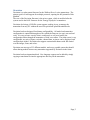
Overview
Deviation is a replacement firmware for the Walkera Devo© series transmitters. The
primary goal is to add support for multiple protocols, opening the full potential of this
platform.
The core of the Deviation firmware is the mixer system, which is modeled after the
system used in the Er9X firmware for the Turnigy/Flysky9x© transmitters.
Deviation also brings a USB file-system support, making it easy to manage the
transmitter from any PC without the need for specialized upload/download tools.
Deviation has been designed for ultimate configurability. All model and transmitter
configuration is controlled through text files which the firmware (or user) can read and
write. It is easy to know exactly what is configured, as well as to modify the
configuration either through the transmitter or with a text editor. The main screen is very
configurable; any mix of inputs, switches, channel data, or timers can be displayed, and
configured per-model. Deviation also supports customizable themes with full control
over the images, fonts, and colors.
Deviation can store up to 255 different models, and uses a portable syntax that should
allow sharing models between any transmitter supported by Deviation in the future.
Deviation has been internationalized. New language support can be added by simply
copying a translation file into the appropriate directory on the transmitter.
Page | 3
Installation
Installation of Deviation is done just like upgrading the Walkera firmware.
Note that Deviation will NOT overwrite Walkera models stored on the Tx. While they
cannot be accessed by Deviation, they will be safely preserved should the Walkera
firmware ever need to be reinstalled.
First install the deviation-x.yy.dfu using the Walkera ‘DfuSe USB Upgrade’ tool.
There are 2 options on how to install the libraries.
If previously the Walkera firmware was installed, the fastest solution is to use the
‘DfuSe’ tool to install the deviation library.
Alternatively (or if this is an upgrade from a previous Deviation version) power off the
Tx, and power back on holding the ‘Ent button (with the USB cable still plugged in).
This will start the Tx in USB mode. Windows will now detect the transmitter as a USB
drive. If the deviation lib was not installed, Windows will ask to format the drive.
Format using the default options. Next unzip the deviation-lib-x.yy.zip to the Tx USB
drive.
USB & File-system
Deviation stores all configuration, bitmaps, and models as regular files on the USB filesystem.
USB can be most easily enabled by holding down the ‘ENT’ button while powering up
the transmitter. Files can then be easily copied to or from the Tx.
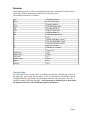
The directory structure is as follows:
\tx.ini
Transmitter config. Includes trim settings, calibration data,
and the last-used model number
\media\config.ini
The color scheme and fonts for the transmitter
\media\sound.ini
Contains notes to play for various alarms
\media\*.bmp
Images used for the current Tx theme
\models\default.ini
The default model, loaded whenever a model is cleared
\models\model*.ini
Configuration files for each model. Due to a limitation in the
firmware, Deviation cannot create new files. It is therefore
necessary to have a modelxx.ini for each model regardless of
whether it is currently in use.
\modelico\*.bmp
All available model icons (must be 96x96 pixels)
\templates\*.ini
Configuration files used when loading predefined templates.
These are nearly identical to the model configuration files,
however they do not necessarily define all parameters
\language\lang*.*
Language translation files. These are UTF-8 text files containing the original English string and the respective translated string
Page | 4
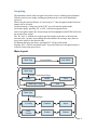
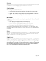
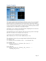
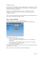
Main Page
Tx Option Pages
Transmitter Power
Current Model
Configurable
displays
Raw input (stick/switch values)
Battery voltage
Model Configuration Pages
Channel Output values
Trims
Tx Option Pages: Selecting this icon provides access to the main-page configuration
screen; the Channel-Test screen; the frequency scanner; and USB mode
Current Model: Selecting the model-name provides access to the Load-Model screen for
quick-model switching
Transmitter Power: This indicates the currently selected transmitter power. It is
configured from the Model Configuration page
Battery Voltage: Numerical representation of current Tx battery state
Configurable Displays: These can be text-boxes contacting input, channel, or timer data;
bar graphs displaying channel data; or icons displaying specific states (e.g. gear, flaps,…)
Trims: The trim display can be configured to show either 4 or 6trims
Model Configuration Pages: Selecting the model icon provides access to the model
configuration pages
Page | 5
Navigating
The transmitter menus can be navigated via touch-screen or with the physical buttons.
With the touch screen, simply touching any button on the screen will immediately
activate it.
When using the physical buttons, it is necessary to 1st enter navigation mode before the
buttons can be accessed.
On the main page, a long-press of the ‘ENT’ key will enter navigation mode.
On all other pages, pressing ‘UP’ or ‘DN’ will enter navigation mode
Once in navigation mode, the current widget will be highlighted, and UP/DN will select
the next/previous widget.
The ‘R+’ and ‘L-’ buttons are used on spin-box widgets to increase or decrease the
selected value. In some cases holding down the button will use larger step values to
move more quickly to the desired value.
For Buttons and gray spin-boxes, pressing ENT’ will press the button
Pressing ‘ESC’ will exit navigation mode. If pressed when not in navigation mode, it
will move back to the main screen
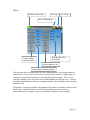
Menu Layout
Main Page
Current Model
Load Model
Main Page
Model Configuration Pages
Mixer
Model
Main Page Config
Timer
Trim
Main Page
Tx Option Pages
Tx Config
Channels
Inputs
USB/
Version
Scanner
Buttons
Page | 6
Emulator
The emulator provides a side-screen displaying the current virtual-stick/switch states as
well as the Channel output that would be received by the servos
The emulator controls are as follows:
q/a
Q/A
w/s
W/S
e/d
E/D
r/f
R/F
z
x
c
v
b
n
\
Left-arrow
Right-arrow
Up-arrow
Down-arrow
Enter
Escape
Throttle (Mode 2)
Left-Vertical trim
Rudder (Mode 2)
Left-Horizontal trim
Elevator(Mode 2)
Right-Vertical trim
Aileron (Mode 2)
Right-Horizontal trim
Gear
Rudder Dual-Rate switch
Elevator Dual-Rate switch
Aileron Dual-Rate switch
Mix 0/1/2 switch
FMode 0/1/2 switch
Power off
Left
Right
Up
Down
Ent
Exit
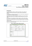
Version Page
The Deviation release version can be accessed by selecting the Configuration icon from
the main page, and moving left two pages. If it is ever necessary to report bugs with the
Deviation firmware, include the version string found here with your report. It is also
possible to enable USB from this page. Note that doing so should never be done while
the model is bound, as USB will disrupt signal transmission!
Page | 7
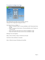
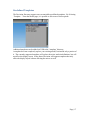
Transmitter Configuration Page
The Configuration page defines various transmitter functions.
Language: Select an appropriate language for all text
Stick Mode: Select one of Mode 1-4.
• Mode 1 is common in Europe. Elevator and Rudder on left, Throttle and Aileron
on right.
• Mode 2 is common in North America. Throttle and Rudder on left, Throttle and
Aileron on right.
• Mode 3 has Elevator and Aileron on left, Throttle and Rudder on right
• Mode 4 has Throttle and Aileron on left, Elevator and Rudder on right
Backlight: Set screen brightness
Battery Alarm: Set battery voltage at which alarm will sound
Touch Screen: Enter calibration or test mode
Sticks: Calibrate the range of all analog sticks and dials
Page | 8
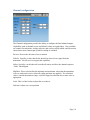
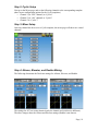
Main Page Configuration
Main Screen Preview
Return to main screen
Next Page
Prev Page
Number of Trims/
Trim Position
Number of channel
bar-graphs to show
Text box enable
and contents
Main Screen Preview
Return to main screen
Next Page
Prev Page
Toggle enable and
Icon chooser
Bar graph channel
configuration
The Main Page Configuration page provides customized control of the main-page layout.
The display of boxes, bars, icons, and trims along with their contents can all be controlled
from here.
Page | 9
Preview
The preview box portrays an approximation of the current configuration, and can be used
as a reference to see how changing options will effect the main screen.
Trim Positions
There are 3 options for the Trim Positions:
•
4 outside: Only 4 trims are shown, and they will be placed at the screen edges
•
4 inside: Only 4 trims are shown, and they are placed at the middle of the screen
•
6 Trims: 6 trims are shown., all placed towards the inside
Bar Graphs
Bar graphs are used to visualize the state of up to 8 output channels. There are 3 possible
configurations:
•
None: Bar graphs are disabled and will not be displayed
•
4 bars: Up to 4 bars will be displayed using one side of the screen
•
8 bars: up to 8 bars will be displayed using both sides of the screen
Bar-graphs will only be displayed if there is room for them. For ‘4 bars’ mode, either
boxes 3&4 or 7&8 need to be disabled. For ‘8 bars’, four boxes: 3, 4, 7 and 8 all need to
be disabled.
Boxes
Boxes are used to display interesting text values Boxes 1, 2, 5, and 6 are large boxes with
a big font. Boxes 3, 4, 7, and 8 are smaller and use a smaller font. Currently a box can
display one of the timers or one of the output channels.
Toggle Icons
Toggle icons are used to display the state of an input or output channel. A toggle is either
on (value > 0) or off (value <= 0). Each toggle can have a different icon shown when it is
active. Up to 4 toggles can be displayed. If only 4 trims are shown, the 4 toggles will replace the area used by trims 5&6. If 6 trims are shown, only 3 toggles can be shown and
they will be placed either in place of box 4 or box 8. The toggles will only be shown if
there is room for them (no box or bar-graph is using that space).
Page | 10
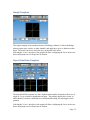
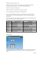
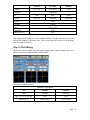
Mixer
Return to main screen
Prev Page
Next Page
Show Chantest page
Channel Output
(and label on Rx)
Switches that effect
the channel
Mixer template in use
Primary input effecting channel
The Deviation mixer is modeled after the Er9x implementation. Each output channel is
composed of a series of one or more mixers each of which consists of a single input, an
activation switch, and a function/curve that modifies the mixer output. This is a very
powerful capability, but it is requires a lot of understanding to make full use of. In order
to simplify implementation, there are 3 templates that have been defined to make defining
channels easier.
The number of channels available is dependent on the number of channels selected on the
Model Page. Additionally there are 10 Virtual channels that can be used as an
intermediate step for complex setups (see Predefined Templates for an example)
Page | 11
Simple Template
The simple template is the simplest manner of defining a channel. It allows defining a
primary-input (stick, switch, or other channel), and applying a curve or function to that
input. The result can also be scaled or have an alternate zero-offset
Selecting the ‘Curve’ spin-box or the graph will allow configuring the Curve in the case
that a multi-point curve or Expo-rate are chosen.
Expo & Dual-Rate Template
The Expo/Dual-Rate template is a more sophisticated template designed to allow use of
toggle or 3-way switches to manipulate an input. The primary-input (stick, switch, or
other channel), can have a different curve/function and scaling for each toggle-switch
position
Selecting the ‘Curve’ spin-box or the graph will allow configuring the Curve in the case
that a multi-point curve or Expo-rate are chosen.
Page | 12
Complex Template
The Complex template unlocks the full power of the mixer system. For a given channel,
any number of mixers can be applied to affect the final result. Each mixer is applied
based on whether the specified switch is active, and can either replace, add to, or multiply
to the previous mixers for this channel. Using this system it should be possible to define
an output channel as a combination of any number of inputs.
Selecting the ‘Curve’ spin-box or the graph will allow configuring the Curve in the case
that a multi-point curve or Expo-rate are chosen.
Note that while the scale value is limited to 100%, the mixer may provide a value larger
than 100% if an offset is set or if the trim value is non-zero.
A given mixer can be considered to have the general form:
M(x) = if(Switch) { Src * Curve * Scale + Offset} else {0} + Trim
The combination of mixers for a given output channel is defined by the Mux type:
For a ‘Replace’ mux:
Cx = if(Switchn) {Mn} else if (Switchn-1) {Mn-1} … else if (Switch0) {M0}
For a ‘Multiply’ mux:
Cx = if(Switchn) {Mn} else {1} * if (Switchn-1) {Mn-1} else {1} * … *
if (Switch0) { M0} else {1}
For an ‘Add’ mux:
Cx = if(Switchn) {Mn} else {0} + if (Switchn-1) {Mn-1} else {0} + … +
if (Switch0) { M0} else {0}
Page | 13
Channel configuration
The Channel configuration provides the ability to configure the final channel outputs.
Capabilities such as channel reverse and failsafe-values are applied here. Also available
are controls for end-points, scaling, sub-trim, and a safety switch (which could be used to
ensure that a motor cannot spin-up while working on a model)
Reverse: Reverse the direction of servo rotation
Failsafe: Specifies a value that the Rx should use when it loses signal from the
transmitter. Not all receivers support this capability.
Safety: Specifies a switch that will override all mixers and force the channel output to
‘Value’ when flipped.
Min/Max: These values define the minimum and maximum values that the transmitter
will ever send to the receiver (after all scaling and trims are applied). If a calculated
value is outside the min/max range, it will be clipped to either the min or max value as
appropriate.
Scale: This is a final scalar to adjust the servo throw.
Sub-trim: Adjust servo zero position
Page | 14
Trims
The trim page allows assigning the trim buttons and trim step. Under normal
circumstances it should not be necessary to modify the trim configuration, however in
some cases it may be desirable to re-purpose unused trims. The Trim-step defines how
sensitive the trims are to input. The maximum number of trim steps is +/-100. So a step
size of 0.1 will allow a full +/- 10% of trim adjustment on the servo.
Model Page
The model page provides various model configuration options.
File: The File spin-box allows loading a new model, copying the existing model to a new
location, resetting the current model to the default (all configuration is lost), and loading
templates (see Predefined Templates)
Model Name: Set the model’s name
Page | 15
Model Icon: Choose the model’s icon
Model Type: Set the model type. Some models (e.g. helicopter) have additional
configuration options that can be accessed by clicking the Model type.
Protocol: Set the type of Rx being used
Number of channels: Sets the number of channels to transmit.
Tx Power: Specify the radio output power when applicable.
Fixed ID: The Fixed ID sets a unique code to ensure that the Tx will only bind to a
specific model. This is useful to ensure that the Tx is not accidentally bound to the
wrong model.
Bind: Depending on the protocol and Fixed-ID setting, the Tx may bind with the model
on start-up, or may need to be manually bound once.
Protocol
Fixed ID = None
Fixed ID set
Devo
Bind on start-up
Manually bind with button
WK2801
Bind on start-up
Manually bind with button
WK2601
Bind on start-up
Bind on start-up
WK2401
Bind on start-up
Bind on start-up
DSM2
Manually bind with button
Manually bind with button
J6Pro
Manually bind with button
Manually bind with button
Flysky
Bind on start-up
Manually bind with button
Timer Page
The timer page defines the 2 available timers. Timers can count either up or down, and
can be enabled either manually from the main screen or by an input trigger (stick or
switch)
Page | 16
Predefined Templates
The Deviation firmware supports user-customizable predefined templates. By Selecting
‘Template...’ From the Model page, it is possible to select one of these options
Additional templates can be added via USB to the ‘\template’ directory.
A template does not completely replace your existing model, but instead only a portion of
it. The currently supported templates will replace the mixer and trim definitions, but will
not affect the display layout. In the future Deviation will support templates that only
affect the display layout without affecting the mixers as well.
Page | 17
Helicopter Setup
Deviation has several configuration options to make setting up a helicopter easier. These
settings are primarily for enabling 6-channel CCPM helicopters. 4-channel helicopters
do not need to follow these instructions.
The easiest way to configure a helicopter is to select ‘6 Ch Helicopter’ from the
‘Template’ section of the model page. This will provide a good starting point for
configuring a helicopter.
However, the following documents step-by-step instructions for configuring a helicopter
from scratch to explain what the template is doing.
Step 1: Type and Swash
Select ‘Helicopter’ as the model-type on the Model Page.
Next click on ‘Helicopter’ on the Model page to open the Helicopter Options page:
The Swash type can be one of:
• None: Use for most flybarless helicopters
• 120: The most common setup for flybar helicopters. 3 servos in 120 degree
configuration
• 120x: The same as 120 but with the ‘aileron’ and ‘elevator’ servos swapped
• 140: An alternative, less-used configuration
• 90: Servos at 90 degrees apart
The ELE Inv, AIL Inv, and COL Inv options let you invert the direction of each primary
input during the Cyclic mixing
Make sure you have at least 6 channels selected on the Model page.
Page | 18
Step 2: Cyclic Setup
Next go to the Mixer page, and set the following channels to the corresponding template
(there are no configuration options for the Cyclic templates)
• Channel 1 (or ‘ELE’ channel) to ‘Cyclic1’
• Channel 2 (or ‘AIL’ channel) to ‘Cyclic2’
• Channel 5 to ‘Cyclic 3’
Step 3: Mixer Setup
Once any channel has been set to a Cyclic template, the mixer page will show new virtual
channels:
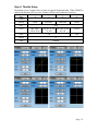
Step 4: Aileron, Elevator, and Rudder Mixing
The following documents the Dual-rate settings for Aileron, Elevator, and Rudder
The settings for all 3 are nearly identical (only the channel and switches are different).
The above images show the Aileron and Elevator settings (Rudder is not shown).
Page | 19
Channel
Aileron
Elevator
Rudder
CYC-AIL
CYC-ELE
Ch3
Template
Expo&DR
Src
Switch1
AIL
ELE
RUD
AIL DR
ELE DR
RUD DR
Switch2
None
Mid-Rate
Linked
Curve
Expo – 45%
Scale(Src)
100%
Scale(Switch1)
60%
This configuration enables low-rates with the dual-rate switches separately for elevator
and aileron channels, with some expo. The low rates have the same curve as the highrates, but with 60% throw.
Step 5: Pitch Mixing
The pitch is setup to enable 3D with Fmode1 and Fmode2. In this example, there is no
difference between usingFMODE1 and FMODE2.
The Pitch is setup as follows:
Template = Expo&DR
Src
Switch1
Switch2
THR
FMODE1
FMODE2
5pt: -30, -15, 0, 50, 100
1-to-1
1-to-1
Scale=100%
Scale=100%
Scale=100%
Page | 20
Step 6: Throttle Setup
The throttle uses a Complex mixer in order to support the throttle-hold. When THOLD is
enabled, the throttle will cut to zero, but the Collective will continue to function.
Page
1
2
# Mixers
Switch
Scale
4
FMODE2
GEAR
1
None
FMODE1
Src
Curve
3
THR
5pt: -100,20,30,70,90
5pt: 80, 70, 60, 5pt: 100, 90, 80,
70, 100
90, 100
100
Fixed
-100
Offset
0
Trim
Enabled
Page | 21