1
Deviation Firmware
User’s Manual
Devo 6/8/12
Version 3.0
Table of Contents
Overview..............................................................................................................................4
Installation............................................................................................................................5
USB & File-system..............................................................................................................6
Main Page............................................................................................................................8
Navigating............................................................................................................................9
Menu Layout...................................................................................................................9
Emulator........................................................................................................................10
Version Page......................................................................................................................10
Transmitter Configuration Page.........................................................................................11
General Settings............................................................................................................11
Buzzer/LCD Settings....................................................................................................11
Timer/Telemetry settings..............................................................................................12
Main Page Configuration (Standard & Advanced GUI)....................................................13
Preview..........................................................................................................................14
Trim Positions...............................................................................................................14
Bar Graphs....................................................................................................................14
Boxes.............................................................................................................................14
Toggle Icons..................................................................................................................14
Quick-page Selection....................................................................................................14
Mixer (Advanced GUI)......................................................................................................15
Channel Reorder............................................................................................................16
Simple Template...........................................................................................................17
Expo & Dual-Rate Template.........................................................................................17
Complex Template........................................................................................................18
Reordering Mixers...............................................................................................................................20
Available Curves...........................................................................................................21
Curve Editing................................................................................................................22
Channel configuration...................................................................................................23
Trims and Virtual Inputs (Standard & Advanced GUI).....................................................24
Model Page (Standard & Advanced GUI).........................................................................24
Protocols........................................................................................................................25
Protocol: DEVO..................................................................................................................................25
Protocol: WK2801...............................................................................................................................25
Page | 2
Protocol: WK2601...............................................................................................................................26
Protocol: WK2401...............................................................................................................................26
Protocol: DSM2...................................................................................................................................26
Protocol: DSMX..................................................................................................................................27
Protocol: J6Pro....................................................................................................................................27
Protocol: Flysky..................................................................................................................................27
Protocol: Hubsan4...............................................................................................................................28
Protocol: Frsky1way (experimental)...................................................................................................28
Protocol: Frsky2way (experimental)...................................................................................................28
Protocol: Skyartec (experimental).......................................................................................................28
Protocol: PPM.....................................................................................................................................29
Predefined Templates....................................................................................................30
Timer Page (Standard & Advanced GUI)..........................................................................31
Telemetry Configuration Page (Standard & Advanced GUI)............................................32
Standard GUI.....................................................................................................................33
Servo Reverse (Standard GUI) .........................................................................................34
Sub-trim Adjustment (Standard GUI)................................................................................35
Servo Travel Adjust (Standard GUI).................................................................................35
Swash Configuration (Standard GUI)................................................................................36
Dual-Rate/Expo setting (Standard GUI)............................................................................36
Throttle Curve (Standard GUI)..........................................................................................37
Pitch Curve (Standard GUI)...............................................................................................37
Gyro Sensitivity (Standard GUI).......................................................................................38
Switch Assignment (Standard GUI)..................................................................................38
Throttle Hold (Standard GUI)............................................................................................39
Fail-Safe Configuration (Standard GUI)...........................................................................39
Helicopter Setup.................................................................................................................40
Step 1: Type and Swash................................................................................................40
Step 2: Cyclic Setup......................................................................................................41
Step 3: Mixer Setup.......................................................................................................41
Step 4: Aileron, Elevator, and Rudder Mixing.............................................................41
Step 5: Pitch Mixing......................................................................................................42
Step 6: Throttle Setup....................................................................................................43
Page | 3
Overview
Deviation is a replacement firmware for the Walkera Devention™ series (Devo)
transmitters. The primary goal is to add support for multiple protocols, opening the full
potential of this platform.
The core of the Deviation firmware is the mixer system, which is modeled after the
system used in the Er9X firmware for the Turnigy/Flysky9x™ transmitters.
Deviation also brings a USB file-system support, making it easy to manage the
transmitter from any PC without the need for specialized upload/download tools.
Deviation has been designed for ultimate configurability. All model and transmitter
configuration is controlled through text files which the firmware (or user) can read and
write. It is easy to know exactly what is configured, as well as to modify the
configuration either through the transmitter or with a text editor. The main screen is very
configurable; any mix of inputs, switches, channel data, or timers can be displayed, and
configured per-model. Deviation also supports customizable themes with full control
over the images, fonts, and colors.
Deviation can store up to 255 different models, and uses a portable syntax that allows
sharing models between any transmitter supported by Deviation.
Deviation has been internationalized. New language support can be added by simply
copying a translation file into the appropriate directory on the transmitter.
Page | 4
Installation
Installation of Deviation is done just like upgrading the Walkera firmware.
Note that Deviation will NOT overwrite Walkera models stored on the Tx. While they
cannot be accessed by Deviation, they will be safely preserved should the Walkera
firmware ever need to be reinstalled (Note: With the Devo12 firmware, the original
models will be lost when switching to Deviation).
First install the deviation-devoXX-x.y.z.dfu firmware using the Walkera ‘DfuSe USB
Upgrade’ tool. You will need the ‘Devention DfuSe USB Upgrade Tool' from Walkera:
http://www.walkera.com/en/upload/upgrade/2013-2-26.rar. Do NOT attempt to use the
DfuSe tool from STMicroelectronics! It is recommended to test that this tool works by
upgrading to a different Walkera firmware. Several users have had compatibility issues
with the DfuSe tool.
Plug the transmitter into the PC via USB, and turn on the transmitter while holding
‘EXT’ to enter programming mode. On the Devo12, this is done by holding the trainerswitch instead.
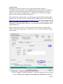
1) Press the ‘...’ button and select the dfu file to install
2) Select ‘Upgrade’ to install the firmware. This will be grayed-out if your Tx is not
detected. Do NOT use ‘Upload’ as this will destroy the dfu file on your PC.
Page | 5
There have been reports of it corrupting the model settings on the TX as
well.
3) Devo12 Only: Select the ’Library’ tab, click ‘..’ select the devo12-lib.dfu from the
file-system zip. Then ‘Upgrade’ the Library.
Turn off the transmitter, and turn back on while holding ‘ENT’. There should be a USB
logo on the screen.
If this is a first-time install of Deviation, the PC should prompt to format the drive.
Format using default options. Next unzip the deviation-fs-devoXX-x.y.z.zip to the Tx
USB drive.
If this is an upgrade from a previous Deviation release, it is strongly recommended to
back-up the ‘models’ directory from the transmitter as well as the tx.ini file to ensure you
don’t lose any model or transmitter configuration. Next unzip the deviation-fs-devoXXx.y.z.zip to the PC and copy all directories EXCEPT for the ‘models’ directory and the
tx.ini file to the transmitter. Optionally, copy the ‘models’ directory to the transmitter
except for the currently configured model files. This last step will ensure that the defaults
for newly created models have the latest options set. If the tx.ini file is overwritten, the
stick calibration must be repeated and any settings reset.
Page | 6
USB & File-system
Deviation stores all configuration, bitmaps, and models as regular files on the USB filesystem.
USB can be most easily enabled by holding down the ‘ENT’ button while powering up
the transmitter. Files can then be easily copied to or from the Tx.
The directory structure is as follows:
\tx.ini
Transmitter config. Includes trim settings, calibration data,
and the last-used model number
\errors.txt
If the firmware crashes or reboots, debug information will be
stored in this
\media\config.ini
The color scheme and fonts for the transmitter
\media\sound.ini
Contains notes to play for various alarms
\media\*.bmp
Images used for the current Tx theme
\media\*.fon
Font files
\models\default.ini
The default model, loaded whenever a model is cleared
\models\model*.ini
Configuration files for each model. Due to a limitation in the
firmware, Deviation cannot create new files. It is therefore
necessary to have a modelxx.ini for each model regardless of
whether it is currently in use.
\modelico\*.bmp
All available model icons (must be 96x96 pixels)
\templates\*.ini
Configuration files used when loading predefined templates.
These are nearly identical to the model configuration files,
however they do not necessarily define all parameters
\language\lang*.*
Language translation files. These are UTF-8 text files containing the English string and the respective translated string
Reporting Bugs
To report bugs with the Deviation firmware, file a ticket at:
https://bitbucket.org/PhracturedBlue/deviation/issues
It is recommended that you create an account in order to be informed of updates to the
ticket, but this is not required.
Please include the Deviation version in all reports (find this on the USB/Version page)
If the bug includes a crash or reboot of the firmware, additionally include:
• The ‘.elf’ files that came with the firmware zip file.
• The errors.txt file from the transmitter
Page | 7
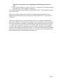
Main Page
Click to edit
Tx Options
Configurable
displays
Transmitter Power
Current
Model
Battery voltage
Click to enter
Model Configuration
Trims
Raw input (stick/switch values)
(Emulator Only)
Channel Output values
(Emulator Only)
Tx Options: Selecting this icon provides access to the main-page configuration screen;
the Channel-Test screen; telemetry output; the frequency scanner; and USB mode
Current Model: Selecting the model-name provides access to the Load-Model screen for
quick-model switching
Transmitter Power: This indicates the currently selected transmitter power. It is
configured from the Model Configuration page
Battery Voltage: Numerical representation of current Tx battery state
Configurable Displays: These can be text-boxes contacting input, channel, telemetry, or
timer data; bar graphs displaying channel data; or icons displaying specific states (e.g.
gear, flaps,…)
Trims: The trim display can be configured to show 0, 4 or 6 trims
Model Configuration: Selecting the model icon provides access to the model
configuration pages
Page | 8
Navigating
The transmitter menus can be navigated via touch-screen or with the physical buttons.
With the touch screen, simply touching any button on the screen will immediately
activate it.
The gray spin-boxes act both as spin-boxes (for selecting a value) and as buttons (which
can have various effects). White spin-boxes do not act as buttons, and are only for value
selection.
When using the physical buttons, it is necessary to 1st enter navigation mode before the
buttons can be accessed.
On the main page, a long-press of the ‘ENT’ key will enter navigation mode.
On all other pages, pressing ‘UP’ or ‘DN’ will enter navigation mode
Once in navigation mode, the current widget will be highlighted, and UP/DN will select
the next/previous widget.
The ‘R+’ and ‘L-’ buttons are used on spin-box widgets to increase or decrease the
selected value. In some cases holding down the button will use larger step values to
move more quickly to the desired value.
For Buttons and gray spin-boxes, pressing ENT’ will press the button
Pressing ‘EXT’ will exit navigation mode. If pressed when not in navigation mode, it
will move back to the main screen
Menu Layout
Main Page
Current Model
Load Model
Main Page
Model Configuration Pages
Mixer
Main Page Config
Main Page
Tx Option Pages
Model
Timer
Trim
Telemetry
USB/
Version
Scanner
Tx Config
Buttons
Telemetry
Channels
Inputs
Page | 9
Emulator
The emulator provides a side-screen displaying the current virtual-stick/switch states as
well as the Channel output that would be received by the servos
The emulator controls are as follows (based an an English keyboard):
Button
q/a
Q/A
w/s
W/S
e/d
E/D
r/f
R/F
z
x
c
v
b
n
\
Left-arrow
Right-arrow
Up-arrow
Down-arrow
Enter
Escape
Action
Left-Vertical stick (Throttle in mode 2)
Left-Vertical trim
Left-Horizontal stick (Rudder in mode 2)
Left-Horizontal trim
Right-Vertical stick (Elevator in mode 2)
Right-Vertical trim
Right-Horizontal stick (Aileron in mode 2)
Right-Horizontal trim
Gear
Rudder Dual-Rate switch
Elevator Dual-Rate switch
Aileron Dual-Rate switch
Mix 0/1/2 switch
FMode 0/1/2 switch
Power off
Left
Right
Up
Down
Ent
Exit
Version Page
The Deviation release version can be accessed by selecting the Configuration icon from
the main page, and moving left one page. It is also possible to enable USB from this
page. Note that doing so should never be done while the model is bound, as USB will
disrupt signal transmission!
Page | 10
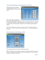
Transmitter Configuration Page
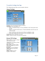
The Configuration page defines various transmitter functions.
General Settings
Language: Select an appropriate language for all text
Stick mode: Select one of Mode 1-4.
• Mode 1 is common in Europe. Elevator and Rudder on left, Throttle and Aileron
on right.
• Mode 2 is common in North America. Throttle and Rudder on left, Elevator and
Aileron on right.
• Mode 3 has Elevator and Aileron on left, Throttle and Rudder on right
• Mode 4 has Throttle and Aileron on left, Elevator and Rudder on right
Touch screen: Enter calibration or test mode
Sticks: Calibrate the range of all analog sticks and dials
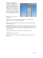
Buzzer/LCD Settings
Battery alarm: Set battery voltage at
which alarm will sound
Alarm intvl: Set frequency of alarm
when battery is low.
Buzz volume: Set buzzer volume
Power-down alert: Play sound at
power-down
Backlight: Set screen brightness
Dimmer time: Set delay before
screen dims
Dimmer target: Set screen
brightness when dimmed
Page | 11
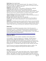
Timer/Telemetry settings
Prealert time: Time before timer
reaches zero to start beeping
Prealert intvl: How often to beep
before timer reaches zero
Timeup intvl: How often to beep once
timer has expired.
Temperature: Set units to display
temperature for telemetry
Length: Set units to display length for
telemetry
Page | 12
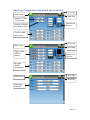
Main Page Configuration (Standard & Advanced GUI)
Main screen
Number of Trims/
Trim Position
Number of channel
bar-graphs to show
Prev Page
Next Page
Main Screen
Preview
Text box enable
and contents
Main screen
Prev Page
Next Page
Toggle enable
and Icon
chooser
Main Screen
Preview
Bar graph
channel
configuration
Main screen
Prev Page
Next Page
Quick-page
Selection
Page | 13
The Main Page Configuration page provides customized control of the main-page layout.
The display of boxes, bars, icons, and trims along with their contents can all be controlled
from here.
Preview
The preview box portrays an approximation of the current configuration, and can be used
as a reference to see how changing options will affect the main screen.
Trim Positions
There are 4 options for the Trim Positions:
•
None: No trim bars are shown
•
4 outside: Only 4 trims are shown, and they will be placed at the screen edges
•
4 inside: Only 4 trims are shown, and they are placed at the middle of the screen
•
6 Trims: 6 trims are shown, all placed towards the inside
Bar Graphs
Bar graphs are used to visualize the state of up to 8 output channels. There are 3 possible
configurations:
•
None: Bar graphs are disabled and will not be displayed
•
4 bars: Up to 4 bars will be displayed using one side of the screen
•
8 bars: up to 8 bars will be displayed using both sides of the screen
Bar-graphs will only be displayed if there is room for them. For ‘4 bars’ mode, either
boxes 3&4 or 7&8 need to be disabled. For ‘8 bars’, four boxes: 3, 4, 7 and 8 all need to
be disabled.
Boxes
Boxes are used to display interesting text values Boxes 1, 2, 5, and 6 are large boxes with
a big font. Boxes 3, 4, 7, and 8 are smaller and use a smaller font. Currently a box can
display one of the timers, one of the output channels, or telemetry data.
Toggle Icons
Toggle icons are used to display the state of an input or output channel. A toggle is either
on (value > 0) or off (value <= 0). Each toggle can have a different icon shown when it is
active. Up to 4 toggles can be displayed. If only 4 trims are shown, the 4 toggles will replace the area used by trims 5&6. If 6 trims are shown, only 3 toggles can be shown and
they will be placed either in place of box 4 or box 8. The toggles will only be shown if
there is room for them (no box or bar-graph is using that space).
Page | 14
Quick-page Selection
Quick-pages allow quick access to other pages from the main page via Left/Right buttons. Up to four quick-pages can be configured.
Page | 15
Mixer (Advanced GUI)
Return to main screen
Prev Page
Next Page
Reorder channels
Show Chantest page
Channel Output
(and label on Rx)
Switches that effect
the channel
Mixer template in use
Primary input effecting channel
The Deviation mixer is modeled after the Er9x implementation. Each output channel is
composed of a series of one or more mixers each of which consists of a single input, an
activation switch, and a function/curve that modifies the mixer output. This is a very
powerful capability, but it is requires a lot of understanding to make full use of. In order
to simplify implementation, there are 3 templates that have been defined to make defining
channels easier.
The number of channels available is dependent on the number of channels selected on the
Model Page (Standard & Advanced GUI). Additionally there are 10 Virtual channels that
can be used as an intermediate step for complex setups (see Helicopter Setup for an
example)
Channels can be reordered by pressing the Reorder Channels button.
Page | 16
Channel Reorder
The Channel reorder page allows moving mixer definitions between channels
as well as duplicating channel configurations. Note that the values displayed
are the initial channel assignments.
Whenever the page is loaded, the channels will be sequentially ordered representing the current state.
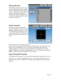
Simple Template
The simple template is the simplest
manner of defining a channel. It allows
defining a primary-input (stick, switch,
or other channel), and applying a curve
or function to that input. The result can
also be scaled or have an alternate zerooffset
Src: The input source controlling this mixer
Curve: The function applied to the input to generate the output. See the Curve section
for more info. Selecting the ‘Curve’ spin-box (or clicking the graph) will allow
configuring the Curve in the case that a multi-point curve or Expo-rate are chosen.
Scale: A multiplicative scalar that is applied after the Curve to control the output range
Offset: an additive offset that is applied after the scaling.
Expo & Dual-Rate Template
The Expo/Dual-Rate template is a more sophisticated template designed to allow use of
toggle or 3-way switches to manipulate an input. The primary-input (stick, switch, or
other channel), can have a different curve/function and scaling for each toggle-switch
position
Page | 17
Selecting a value for Switch1 or
Switch2 will activate the
corresponding section. Each section
can either have a 'linked' curve (curve
is the same as the 'High-Rate' curve)
in which case only the scalar can be
modified, or alternatively can have an
independent curve definition.
Pressing the 'Mid-Rate' or 'Low-Rate'
button for a given switch will toggle
between linked and independent
curves.
Src: The input source controlling this mixer
Curve: The function applied to the input to generate the output. See the Curve section
for more info. Selecting the ‘Curve’ spin-box (or clicking the graph) will allow
configuring the Curve in the case that a multi-point curve or Expo-rate are chosen.
Switch: Specify a switch to enable Medium or Low rates.
Scale: A multiplicative scalar that is applied after the Curve to control the output range
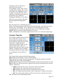
Complex Template
The Complex template unlocks the full
power of the mixer system. For a
given channel, any number of mixers
can be applied to affect the final result.
Each mixer is applied based on
whether the specified switch is active,
and can either replace, add to, or
multiply to the previous mixers for this
channel. Using this system it should
be possible to define an output channel
as a combination of any number of
inputs.
The Complex Mixer page has the following options:
Mixers: Specify the number of mixers for this channel
Page: Specify the current mixer page being edited. Pressing the spin-box will allow
reordering the pages of the current channel.
Switch: Specify an optional switch which determines whether the current mixer is active.
Mux: Defines how the current mixer is applied to the previously defined mixers for this
channel. Options are:
• Replace: If this mixer is active, all previous mixers are ignored
• Add: Add the value of this mixer to the previous mixers
• Mult: Multiply the value of this mixer with the previous mixers
• Max: The output will be the greater of the current mixer vs the previous mixers
• Min: The output will be the lesser of the current mixer vs the previous mixers
Src: The input source controlling this mixer
Page | 18
Curve: The function applied to the input to generate the output. See the Curve section
for more info. Selecting the ‘Curve’ spin-box will allow configuring the Curve in the
case that a multi-point curve or Expo-rate are chosen.
Scale: A multiplicative scalar that is applied after the Curve to control the output range
Offset: an additive offset that is applied after the scaling.
Trim: Selects whether or not any trims for the selected Source are applied to this mixer
Note that while the scale value is limited to 100%, the mixer may provide a value larger
than 100% if an offset is set or if the trim value is non-zero.
A given mixer can be considered to have the general form:
M(x) = if(Switch) { Src * Curve * Scale + Offset} else {0} + Trim
The combination of mixers for a given output channel is defined by the Mux type:
For a ‘Replace’ mux:
Cx = if(Switchn) {Mn} else if (Switchn-1) {Mn-1} … else if (Switch0) {M0}
For a ‘Multiply’ mux:
Cx = if(Switchn) {Mn} else {1} * if (Switchn-1) {Mn-1} else {1} * … *
if (Switch0) { M0} else {1}
For an ‘Add’ mux:
Cx = if(Switchn) {Mn} else {0} + if (Switchn-1) {Mn-1} else {0} + … +
if (Switch0) { M0} else {0}
For a ‘Max’ mux:
Cx = MAX(if(Switchn) {Mn} else {0}, if (Switchn-1) {Mn-1} else {0}, …,
if (Switch0) { M0} else {0})
For a ‘Min’ mux:
Cx = MIN(if(Switchn) {Mn} else {0}, if (Switchn-1) {Mn-1} else {0}, …,
if (Switch0) { M0} else {0})
Reordering Mixers
Since the ordering of mixers is important to the output, it is possible to
reorder and/or copy mixers in order
to facilitate building complex rules.
This page is accessed by pressing the
‘Page’ spin-box on the complex
mixer page.
Page | 19
Select the respective mixer and use the up/down buttons to move the order of the selected
mixer. Note that the mixer name represents its position when the reorder dialog was
opened. If the dialog is closed and reopened, all mixers will be shown as numbered sequentially.
The reorder page can add new mixers or delete existing ones using the ‘Insert’ and ‘Remove’ buttons respectively. A mixer can also be copied to an existing mixer (overwriting
it in the process) by using the ‘Copy To’ functionality
Available Curves
The following curve functions are supported:
1-to-1: Output is equal to the input (not editable).
Fixed: Output is constant regardless of input (not editable).
Min/Max: Output is -100 if input is < 0 and 100 if input is >= 0 (not editable)
Zero/Max: Output is 0 if input is < 0 and 100 if input is >= 0 (not editable)
>0: Output is 0 if input is < 0 and matches the input when >= 0 (not editable)
<0: Output matches the input when < 0 and is 0 if input >= 0 (not editable)
ABSVAL: Output is the absolute-value of the input (not editable)
EXPO: Apply exponential curve to the input for non-linear response (editable)
Deadband: Output will not respond to input values near zero (editable)
Multi-point: Curve is based on 3 to 13user-defined points
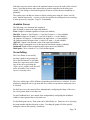
Curve Editing
The Curve Editor is accessed by
pressing a graph or by pressing the
curve spin-box when it is selectable.
Some curve types may not be edited
(any of the curves preceding the
‘Expo’ curve), and the curve-box will
not be selectable if one of these
curves is currently active.
The Curve editor page will be difference depending on which curve is selected. It is not
possible to change the curve type from the curve editor (except when a multi-point curve
is selected)
For the Expo curve, the controls allow independently configuring the shape of the curve
for values greater-than or less-than zero.
For the Deadband curve, the controls allow independently configuring the deadband
width for values greater-than or less-than zero.
For the Multi-point curves, Each point can be individually set. Points are set by choosing
the point number and then choosing a value. Touching the graph will allow quickly
setting the value to the touched y-coordinate.
Page | 20
Channel configuration
The Channel configuration provides
the ability to configure the final
channel outputs. Capabilities such as
channel reverse and fail-safe values
are applied here. Also available are
controls for end-points, scaling, subtrim, and a safety switch (which could
be used to ensure that a motor cannot
spin-up while working on a model)
Reverse: Reverse the direction of
servo rotation
Failsafe: Specifies a value that the Rx should use when it loses signal from the
transmitter. Not all receivers support this capability.
Safety: Specifies a switch that will override all mixers and force the channel output to
‘Safe Val’ when flipped.
Min Limit/Max Limit: These values define the minimum and maximum values that the
transmitter will ever send to the receiver (after all scaling and trims are applied). If a
calculated value is outside the min/max range, it will be clipped to either the min or max
value as appropriate.
Scale+/Scale-: These values define a final scalar to adjust the servo throw.
Sub-trim: Adjust servo zero position
Speed: Adjust maximum servo speed. Zero is disabled (fastest), 1 is slowest, 100 is
fastest rate.
Page | 21
Trims and Virtual Inputs (Standard & Advanced GUI)
The trim page allows assigning the
trim buttons and trim step, as well as
configuring buttons to work as virtual
inputs.
If the ‘Input’ field is set to an input
stick, then the trim is applied as part of
the mixer, and will operate as a typical trim control. If the ‘Input’ field is set as a channel
or virtual-channel output, the value is applied directly to the channel output. In this case,
the selected ‘Pos’ and ‘Neg’ buttons can operate as a virtual stick to control an output
channel.
The Trim-step defines how sensitive the trims are to input. The maximum number of
trim steps is +/-100. So a step size of 0.1 will allow a full +/- 10% of trim adjustment on
the servo.
Model Page (Standard & Advanced GUI)
The model page provides various model configuration options.
File: The File spin-box allows loading a new model, copying the existing model to a new
location, resetting the current model to the default (all configuration is lost), and loading
templates (see Predefined Templates)
Page | 22
Model Name: Set the model’s name
Mixer GUI: Defines which GUI to use for this model. The ‘Advanced’ GUI is the
default for Deviation. The ‘Standard’ GUI is only available for Helicopter models and
more closely resembles a traditional vendor GUI.
Model Icon: Choose the model’s icon
Model Type: Set the model type. Some models (e.g. helicopter) have additional
configuration options that can be accessed by clicking the Model type.
Protocol: Set the type of Rx being used. Note that some protocols have additional
options that can be accessed by pressing the Protocol spin-box when it is active. See the
Protocol section for more on specific protocols. Note that a protocol change will take
effect immediately and could cause a bound model to behave erratically.
Number of channels: Sets the number of channels to transmit (the maximum number of
channels is dependent on the selected protocol).
Tx Power: Specify the radio output power when applicable.
Fixed ID: The Fixed ID sets a unique code to ensure that the Tx will only bind to a
specific model. This is useful to ensure that the Tx is not accidentally bound to the
wrong model.
Bind/Re-Init: Depending on the protocol and Fixed-ID setting, the Tx may bind with the
model on start-up, or may need to be manually bound once. See the Protocol section for
more on specific protocols. If the protocol does not support binding, the button will show
‘Re-Init’, which can be used to switch protocols without power-cycling the transmitter.
Protocols
Some protocols have additional customization or limits. Each of the protocols is
described below. If an ‘*’ is shown before the protocol name, it means this protocol is
not currently supported by the transmitter. This generally means that the necessary
hardware module is not installed or has not been configured properly. More information
can be found in the Module installation guide:
http://www.deviationtx.com/repository/Documentation/ModuleInstallation.pdf/
Protocol: DEVO
The DEVO protocol is used to maintain compatibility with the Walkera DEVO
receivers/models. This protocol supports up to 12 channels. The DEVO protocol
supports both auto-binding and manual-binding. If FixedID is set to ‘None’ the
transmitter will attempt to auto-bind with the receiver every time it is powered n. If a
value is set for FixedID, the receiver must be bound manually one-time using the ‘Bind’
button, after which it should stay bound. Note that the FixedID is only part of the
binding procedure. Two transmitters with the Same ID cannot control the same model.
The DEVO protocol also supports enabling/disabling the telemetry capability. This
option is accessed by pressing the Protocol spin-box when DEVO is shown.
Protocol: WK2801
The WK2801 protocol is used to control older Walkera models. The previous Walkera
models were segmented into 3 similar but not identical protocols: WK2801, WK2601,
WK2401. This roughly corresponds to the number of channels supported, but many of
the newer 6-channel receivers actually support the WK2801 protocol. It is recommended
Page | 23
to try the WK2801 protocol 1st when working with older Walkera models before
attempting the WK2601 or WK2401 mode, as the WK2801 is a superior protocol. The
WK2801 protocol supports up to 8 channels, and both auto-binding and manual-binding.
If FixedID is set to ‘None’ the transmitter will attempt to auto-bind with the receiver
every time it is powered on. If a value is set for FixedID, the receiver must be bound
manually one-time using the ‘Bind’ button, after which it should stay bound.
Protocol: WK2601
The WK2601 protocol is used to control older Walkera models. The previous Walkera
models were segmented into 3 similar but not identical protocols: WK2801, WK2601,
WK2401. This roughly corresponds to the number of channels supported, but many of
the newer 6-channel receivers actually support the WK2801 protocol. It is recommended
to try the WK2801 protocol 1st when working with older Walkera models before
attempting the WK2601 or WK2401 mode, as the WK2801 is a superior protocol. The
WK2601 protocol supports up to 7 channels, and only supports auto-binding. The fixed
ID can be used, but does not prevent auto-binding during power-on.
The WK2601 protocol also supports additional options. These are accessed by pressing
the Protocol spin-box when Wk2601 is shown:
Chan mode: Sets how channels are processed:
• 5+1: AIL, ELE, THR, RUD, GYRO (ch 7) are proportional. Gear (ch 5) is
binary. Ch 6 is disabled
• Heli: AIL, ELE, THR, RUD, GYRO are proportional. Gear (ch 5) is binary. COL
(ch 6) is linked to Thr. If Ch6 >= 0, the Rx will apply a 3D curve to the Thr. If
Ch6 < 0, the Rx will apply normal curves to the Thr. The value of Ch6 defines
the ratio of COL to THR.
• 6+1: AIL, ELE, THR, RUD, COL (ch 6), GYRO (ch 7) are proportional. Gear
(ch 5) is binary. This mode is highly experimental.
COL Inv: Invert COL servo
COL Limit: Set maximum range of COL servo
Protocol: WK2401
The WK2401 protocol is used to control older Walkera models. The previous Walkera
models were segmented into 3 similar but not identical protocols: WK2801, WK2601,
WK2401. This roughly corresponds to the number of channels supported, but many of
the newer 6-channel receivers actually support the WK2801 protocol. It is recommended
to try the WK2801 protocol 1st when working with older Walkera models before
attempting the WK2601 or WK2401 mode, as the WK2801 is a superior protocol. The
WK2401 protocol supports up to 4 channels, and only supports auto-binding. The fixed
ID can be used, but does not prevent auto-binding during power-on.
Protocol: DSM2
The DSM2 protocol is used to control many Spektrum™ and JR™, as well as other
models using this protocol. While the DSM2 protocol can support up to 14 channels,
Deviation is currently limited to a maximum of 12. Note that many receivers with less
than 8 channels require the Transmitter to send 7 or less channels. Make sure the # of
channels is set appropriately for the receiver. DSM2 does not support auto-binding.
Page | 24
If FixedID is set to None, a transmitter-specific ID is used instead. It is necessary to
manually bind each model before the first use.
The DSM2 protocol also supports enabling/disabling the telemetry capability. This
option is accessed by pressing the Protocol spin-box when DSM2 is shown.
Protocol: DSMX
The DSMX protocol is used to control many Spektrum™ and JR™, as well as other
models using this protocol. While the DSMX protocol can support up to 14 channels,
Deviation is currently limited to a maximum of 12. Note that many receivers with less
than 8 channels require the Transmitter to send 7 or less channels. Make sure the # of
channels is set appropriately for the receiver. DSMX does not support auto-binding.
If FixedID is set to None, a transmitter-specific ID is used instead. It is necessary to
manually bind each model before the first use.
Note that unlike Spektrum™ or JR™ transmitters, Deviation will not automatically select
between DSM2 and DSMX. The user must select which protocol to use.
The DSMX protocol also supports enabling/disabling the telemetry capability. This
option is accessed by pressing the Protocol spin-box when DSMX is shown.
Protocol: J6Pro
The J6Pro protocol is used to support Nine Eagles™ models. Only models compatible
with the J6Pro transmitter can be used. Many older 4-channel Nine Eagles models used a
different protocol that is unsupported. The J6Pro protocol supports up to 12 channels,
although only models with 6 channels have been tested. J6Pro does not support autobinding. If FixedID is set to None, a transmitter-specific ID is used instead. It is
necessary to manually bind each model before the first use.
Protocol: Flysky
The Flysky protocol is used to control Turnigy/Flysky receivers as well as a few other
models using the same protocol (WL V911, Xieda 9958, etc). NOTE: This protocol
requires the addition of an ‘A7105’ hardware module to function. See the following
document for more information:
http://www.deviationtx.com/repository/Documentation/ModuleInstallation.pdf/
The Flysky protocol supports up to 8 channels, and both auto-binding and manualbinding. If FixedID is set to ‘None’ the transmitter will attempt to auto-bind with the
receiver every time it is powered on. If a value is set for FixedID, the receiver must be
bound manually one-time using the ‘Bind’ button, after which it should stay bound.
The Flysky protocol also supports additional options. These are accessed by pressing the
Protocol spin-box when Flysky is shown:
WLToys V9x9: Enables enhanced protocol configuration for use with WLToys V959,
v969, etc models:
• Lights are controlled by Channel 5
• Video is controlled by Channel 6
Page | 25
• Camera is controlled by Channel 7
Note that if these channels are assigned to a switch, turning the switch on toggles the
state, and turning the switch off has no effect. Thus to turn the lights on, flip the switch
assigned to Channel 5 from off to on. Flipping the switch back to off has no effect.
Flipping the switch back on now turns the lights back off.
Protocol: Hubsan4
The Hubsan4 protocol supports the Hubsan-X4 quadracopter. No other models have
been tested with this protocol. NOTE: This protocol requires the addition of an ‘A7105’
hardware module to function. See the following document for more information:
http://www.deviationtx.com/repository/Documentation/ModuleInstallation.pdf/
The Hubsan4 protocol supports 4 channels, and only supports auto-binding. The fixed ID
can be used, but does not prevent auto-binding during power-on.
Protocol: Frsky1 (experimental)
The Frsky1 protocol is used to control older (non-telemetry) Frsky™ receivers using the
one-way protocol.
NOTE: This protocol requires the addition of a ‘CC2500’ hardware module to function.
See the following document for more information:
http://www.deviationtx.com/repository/Documentation/ModuleInstallation.pdf/
The Frsky1way protocol supports 4 channels, does not support auto-binding. If FixedID
is set to None, a transmitter-specific ID is used instead. It is necessary to manually bind
each model before the first use.
Protocol: Frsky2 (experimental)
The Frsky2 protocol is used to control newer (telemetry enabled) Frsky™ receivers using
the two-way protocol.
NOTE: This protocol requires the addition of a ‘CC2500’ hardware module to function.
See the following document for more information:
http://www.deviationtx.com/repository/Documentation/ModuleInstallation.pdf/
The Frsky2way protocol supports up to 8 channels, does not support auto-binding. If
FixedID is set to None, a transmitter-specific ID is used instead. It is necessary to
manually bind each model before the first use.
The Frsky2way protocol also supports enabling/disabling the telemetry capability. This
option is accessed by pressing the Protocol spin-box when Frsky2way is shown.
Protocol: Skyartec (experimental)
The Skyartec protocol is used to control Skyartec™ receivers and models.
NOTE: This protocol requires the addition of a ‘CC2500’ hardware module to function.
See the following document for more information:
http://www.deviationtx.com/repository/Documentation/ModuleInstallation.pdf/
Page | 26
The Skyartec protocol supports up to 7 channels, does not support auto-binding. If
FixedID is set to None, a transmitter-specific ID is used instead. It is necessary to
manually bind each model before the first use.
Protocol: PPM
The PPM protocol is used to output PPM on the trainer port. It will disable all radio
transmission. The PPM protocol is useful for connecting to simulators, or other radiomodules that plug into the trainer port. The FixedID has no effect, and there is no
binding associated with this protocol.
Deviation does not auto-detect when a trainer cord is plugged into the transmitter. To use
Deviation with a simulator (such as Phoenix), create a new model, name it appropriately,
and select PPM as the protocol. Use the Re-Init button or power-cycle to enable PPM
mode.
The Flysky protocol also supports additional options. These are accessed by pressing the
Protocol spin-box when Flysky is shown:
• Center PW: defines the pulse-width when sticks are centered
• Delta PW: defines the change in pulse-width when channel value is +/-100%
• Notch PW: defines the delay between channels
• Frame Size: defines the total time for all channels to be transferred
Predefined Templates
The Deviation firmware supports
user-customizable predefined
templates. By Selecting ‘Template...’
from the Model page, it is possible to
select one of these options
Additional templates can be added via
USB to the ‘\template’ directory.
A template does not completely
replace your existing model, but
instead only a portion of it. The
currently supported templates will
replace the mixer and trim definitions, but will not affect the display layout. In the future
Deviation will support templates that only affect the display layout without affecting the
mixers as well.
Page | 27
Timer Page (Standard & Advanced GUI)
The timer page defines up to 4
available timers. Timers can count
either up or down, and can be
enabled either manually from the
main screen or by an input trigger
(stick or switch).
Timers can also be optionally
configured to be reset via an
alternate switch (only when using the
Advanced GUI).
The ‘permanent’ timers have their
values saved in the model.ini file and will maintain their previous value when powering
up the transmitter.
Page | 28
Telemetry Configuration Page (Standard & Advanced GUI)
The telemetry configuration page allows specifying alarms when specific telemetry
events occur.
Telemetry: Specify the telemetry input to use for alarm control. This can be a
temperature probe, voltage probe, or RPM probe.
Equality: Can be '>=' or '<=' indicating whether a value above or below the target causes
an alarm.
Target: The target value for the alarm
Page | 29
Standard GUI
The Standard GUI is an alternative interface from the Advanced GUI’. Which interface
is used is chosen by the ‘Mixer GUI’ on the Model Page. The Standard GUI is only
available for Helicopter-type models at this time. The pages of the Standard GUI are as
follows:
Model configuration (See page 22)
Servo reverse (See page 31)
Servo sub-trim (See page 32)
Servo travel-adjust (See page 32)
Swash Setup (See page 33)
Dual-rates setup (See page 33)
Throttle curve setup (See page 34)
Pitch curve setup (See page 34)
Gyro-sense configuration (See page 35)
Trim configuration (See page 22)
Page | 30
Switch assignment (See page 35)
Throttle-hold configuration (See page 36)
Fail-Safe configuration (See page 36)
Timer configuration (See page 28)
Telemetry configuration (See page 29)
Main page configuration (See page 13)
Servo Reverse (Standard GUI)
The servo reverse page allows quickly setting each channel to work in either normal or
reversed mode. These settings are equivalent to the ‘Reverse’ setting on the Channel
Configuration sub-page of the Mixer menu when using the Advanced Mixer (see page
21)
Page | 31
Sub-trim Adjustment (Standard GUI)
The sub-trim adjust page allows setting the zero-point of the servos for each channel.
This is equivalent to the ‘Subtrim’ setting on the Channel Configuration sub-page of the
Mixer menu when using the Advanced Mixer (see page 21)
Servo Travel Adjust (Standard GUI)
The servo-travel adjust page configures the maximum positive/negative travel of each
servo. This is equivalent to the ‘Scale+’ and ‘Scale-’ settings on the Channel
Configuration sub-page of the Mixer menu when using the Advanced Mixer (see page
21)
Page | 32
Swash Configuration (Standard GUI)
The Swash configuration page configures the swash type. These settings are equivalent
to the settings on the 'Helicopter’ configuration sub-page of the Model page (see page
22).
The available values are:
• 1Servo: Used For FBL. All mixing occurs in Rx
• 3Servo 120: 120-degree swash
• 3Servo 120x: 120 degrees swash (alternate config)
• 3Servo 140: 140 degree swash
• 3Servo 90: 90 degrees swash
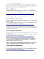
Dual-Rate/Expo setting (Standard GUI)
The dual-rate and expo page allows configuration of curves for the Aileron, Rudder, and
Elevator channels. Up-to 3 rates can be configured for each channel, and either a scaledlinear or exponential curve can be selected for each. The number of settings depends on
the switch assigned to the dual-rates function on the Switch Assignment page (see page
35)
Page | 33
Throttle Curve (Standard GUI)
The throttle curve page allows defining a piece-wise linear curve for the throttle channel.
Different curves can be selected for each flight-mode. Selecting ‘Auto’ enables any
given point to be interpolated from the points surrounding it.
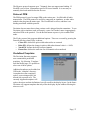
Pitch Curve (Standard GUI)
The pitch curve allows defining a piece-wise linear curve for the collective/pitch channel.
Different curves can be selected for each flight-mode as well as for throttle-hold.
Selecting ‘Auto’ enables any given point to be interpolated from the points surrounding
it.
Page | 34
Gyro Sensitivity (Standard GUI)
The gyro-sensitivity page enables configuring up-to 3 sensitivity values for the gyro as
well as which channel to use for sending the gyro value.
Switch Assignment (Standard GUI)
The switch assignment page enables configuring which switches to use for each
capability in the standard-GUI. The same switch may be assigned to multiple
capabilities.
Page | 35
Throttle Hold (Standard GUI)
The throttle-hold page is used to enable/disable the throttle-hold capability. Specifying
‘Hold position’ defines the throttle value when the Throttle-hold switch is set.
Fail-Safe Configuration (Standard GUI)
The fail-safe page is used to configure the fail-safe value for each channel (if the protocol
supports this feature)
Page | 36
Helicopter Setup
Deviation has several configuration options to make setting up a helicopter easier. These
settings are primarily for enabling 6-channel CCPM helicopters. 4-channel helicopters
do not need to follow these instructions.
The easiest way to configure a helicopter is to select ‘6 Ch Helicopter’ from the
‘Template’ section of the model page. This will provide a good starting point for
configuring a helicopter. However, the following documents step-by-step instructions for
configuring a helicopter from scratch to explain what the template is doing.
Step 1: Type and Swash
Select ‘Helicopter’ as the model-type on the Model Page.
Next click on ‘Helicopter’ on the Model page to open the Helicopter Options page:
The Swash type can be one of:
• None: Use for most flybarless helicopters
• 120: The most common setup for flybar helicopters. 3 servos in 120 degree
configuration
• 120x: The same as 120 but with the ‘Aileron’ and ‘Elevator’ servos swapped
• 140: An alternative, less-used configuration
• 90: Servos at 90 degrees apart
The ELE Inv, AIL Inv, and COL Inv options let you invert the direction of each primary
input during the Cyclic mixing
The ELE Mix, AIL Mix, and COL Mix control the relative percentage of each primary
input during Cyclic mixing. Note that the values are normalized to a sum of 180. So
there is no difference between a setting of 60/60/60 and 100/100/100.
Make sure you have at least 6 channels selected on the Model page.
Page | 37
Step 2: Cyclic Setup
Next go to the Mixer page, and set the following channels to the corresponding template
(there are no configuration options for the Cyclic templates)
• Channel 1 (or ‘ELE’ channel) to ‘Cyclic1’
• Channel 2 (or ‘AIL’ channel) to ‘Cyclic2’
• Channel 5 to ‘Cyclic 3’
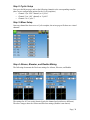
Step 3: Mixer Setup
Once any channel has been set to a Cyclic template, the mixer page will show new virtual
channels:
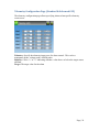
Step 4: Aileron, Elevator, and Rudder Mixing
The following documents the Dual-rate settings for Aileron, Elevator, and Rudder
The settings for all 3 are nearly identical (only the channel and switches are different).
The above images show the Aileron and Elevator settings (Rudder is not shown).
Page | 38
Channel
Aileron
Elevator
Rudder
CYC-AIL
CYC-ELE
Ch3
Template
Expo&DR
Src
Switch1
AIL
ELE
RUD
AIL DR
ELE DR
RUD DR
Switch2
None
Mid-Rate
Linked
Curve
Expo – 45%
Scale(Src)
100%
Scale(Switch1)
60%
This configuration enables low-rates with the dual-rate switches separately for Elevator
and Aileron channels, with some Expo. The low rates have the same curve as the highrates, but with 60% throw.
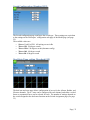
Step 5: Pitch Mixing
The pitch is setup to enable 3D with FMODE1 and FMODE2. In this example, there is
no difference between using FMODE1 and FMODE2.
The Pitch is setup as follows:
Template = Expo&DR
Src
Switch1
Switch2
THR
FMODE1
FMODE2
5pt: -30, -15, 0, 50, 100
1-to-1
1-to-1
Scale=100%
Scale=100%
Scale=100%
Page | 39
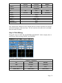
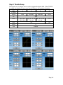
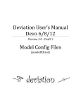
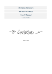
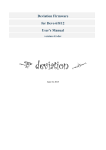
Step 6: Throttle Setup
The Throttle uses a complex mixer in order to support the throttle-hold. When THOLD
is enabled, the throttle will cut to zero, but the Collective will continue to function.
Page
1
2
# Mixers
Switch
Scale
4
FMODE2
GEAR
1
None
FMODE1
Src
Curve
3
THR
5pt: -100,20,30,70,90
5pt: 80, 70, 60, 5pt: 100, 90, 80,
70, 100
90, 100
100
Fixed
-100
Offset
0
Trim
Enabled
Page | 40