1
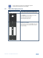
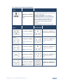
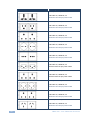
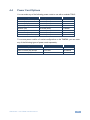
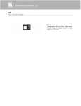
K R A ME R E LE CT R O N IC S L T D .
USER MANUAL
MODEL:
MODULAR TBUS-10xl
Table Connection Bus
P/N: 2900-300224 Rev 1
Contents
1
Introduction
1
2
2.1
2.2
2.3
3
Getting Started
Achieving the Best Performance
Glossary
Recycling Kramer Products
Overview
2
2
3
3
4
4
4.1
4.2
4.3
4.4
Your TBUS-10xl Enclosure
TBUS-10xl Optional Inner Frames
TBUS-10xl Optional Inserts
Power Socket Options
Power Cord Options
5
6
7
8
11
5
5.1
5.2
5.3
5.4
5.5
5.6
5.7
6
Installing the TBUS-10xl
Assembling the Inner Frame
Installing the Inner Frame
Cutting an Opening in the Table
Inserting the TBUS-10xl through the Cut Out Opening
Connecting the Cables
Inserting Pass-through Cables
Adjusting the Height of the Inner frame
Using the TBUS-10xl
12
12
18
19
20
21
21
22
23
7
Technical Specifications of the Assembled TBUS-10xl
24
Figures
Figure 1: TBUS-10xl Enclosure Top View
Figure 2: TBUS-10xl Inner Frame (P/N: 80-000028)
Figure 3: Installing the MegaTOOL
Figure 4: T-RC8IR (P/N: 80-000599)
Figure 5: Removing the RC-8IR Faceplate
Figure 6: T-RC8IR Installation
Figure 7: Removing the Button Cover Plate Mounting Screws
Figure 8: T-RC-76/T-RC-78 Installation
Figure 9: Cut out Dimensions
Figure 10: Inserting TBUS-10xl into the Prepared Opening
Figure 11: TBUS-10xl Boardroom Installation
5
13
14
15
15
16
17
17
19
20
23
TBUS-10xl – Contents
i
1
Introduction
Welcome to Kramer Electronics! Since 1981, Kramer Electronics has been
providing a world of unique, creative, and affordable solutions to the vast range of
problems that confront video, audio, presentation, and broadcasting professionals
on a daily basis. In recent years, we have redesigned and upgraded most of our
line, making the best even better!
Our 1,000-plus different models now appear in 11 groups that are clearly defined
by function: GROUP 1: Distribution Amplifiers; GROUP 2: Switchers and Routers;
GROUP 3: Control Systems; GROUP 4: Format/Standards Converters; GROUP 5:
Range Extenders and Repeaters; GROUP 6: Specialty AV Products; GROUP 7:
Scan Converters and Scalers; GROUP 8: Cables and Connectors; GROUP 9:
Room Connectivity; GROUP 10: Accessories and Rack Adapters and GROUP 11:
Sierra Video Products.
Thank you for purchasing the Kramer TBUS-10xl enclosure, which is ideal for
boardrooms, conference and training rooms!
i
Note that the inner frame, power socket assembly, power cord and
other inserts for the TBUS-10xl enclosure are purchased
separately.
TBUS-10xl - Introduction
1
2
Getting Started
We recommend that you:
Unpack the equipment carefully and save the original box and packaging
•
materials for possible future shipment
Review the contents of this user manual
•
i
2.1
Go to http://www.kramerelectronics.com to check for up-to-date
user manuals, a complete list of Kramer wall plates and module
connectors, application programs, and to check if firmware
upgrades are available (where appropriate).
Achieving the Best Performance
To achieve the best performance:
Use only good quality connection cables (we recommend Kramer high-
•
performance, high-resolution cables) to avoid interference, deterioration in
signal quality due to poor matching, and elevated noise levels (often
associated with low quality cables)
Do not secure the cables in tight bundles or roll the slack into tight coils
•
•
Avoid interference from neighboring electrical appliances that may adversely
influence signal quality
•
Position your Kramer TBUS-10xl away from moisture, excessive sunlight
and dust
2
!
This equipment is to be used only inside a building. It may only be
connected to other equipment that is installed inside a building.
!
There are no operator serviceable parts inside the unit.
TBUS-10xl - Getting Started
2.2
2.3
Glossary
Inner frame:
The inner frame fits into the TBUS enclosure
Universal socket:
The Universal socket fits almost all power cords, worldwide
Insert:
The insert fits into the inner frame. Go to our Web site to check for a
variety of single and dual sized inserts
Recycling Kramer Products
The Waste Electrical and Electronic Equipment (WEEE) Directive 2002/96/EC
aims to reduce the amount of WEEE sent for disposal to landfill or incineration by
requiring it to be collected and recycled. To comply with the WEEE Directive,
Kramer Electronics has made arrangements with the European Advanced
Recycling Network (EARN) and will cover any costs of treatment, recycling and
recovery of waste Kramer Electronics branded equipment on arrival at the EARN
facility. For details of Kramer’s recycling arrangements in your particular country
go to our recycling pages at http://www.kramerelectronics.com/support/recycling/.
TBUS-10xl - Getting Started
3
3
Overview
The Kramer TBUS-10xl is a high-quality, anodized aluminum, table-mounted
connection bus enclosure for boardrooms and conference rooms. Its attractive
enclosure is designed to provide maximum connectivity in the smallest possible
footprint. The unit is sturdy, cost-effective, and easy to install.
The TBUS-10xl:
Has a modular design, letting you tailor the TBUS-10xl according to your
•
requirements
Is available in a black anodized or brushed clear anodized aluminum lid with
•
a special opening for cable pass-through (note, that other customized colors
can also be ordered)
Includes height adjustment screw holes to set the inner frame (ordered
•
separately) to the desired height
Features a cover that opens and closes manually and retracts into the unit to
•
remain out of sight when the TBUS-10xl is in use. When closed, all cables
and connectors are out-of-sight under the anodized cover
!
4
Do not place heavy objects on top of the TBUS-10xl.
TBUS-10xl - Overview
4
Your TBUS-10xl Enclosure
This section defines the TBUS-10xl enclosure and the Inner frame options.
Figure 1: TBUS-10xl Enclosure Top View
TBUS-10xl - Your TBUS-10xl Enclosure
5
1
#
Feature
Outer Rim
Function
Fits over the table surface.
A protective rubber guard protects the outer rim during
shipping. Remove it before installing the unit
2
Inner Frame
Installed within the TBUS-10xl enclosure
3
Black Anodized/Brushed Includes an opening for cable pass-through; covers the inner
frame, leaving the table surface neat and tidy
Clear Anodized
Textured Lid
4
Lid Housing
When opened, the lid retracts into the lid housing
5
Height Adjustment
Screw holes
The screw holes on each side panel are used for mounting
and adjusting the height of the Inner Frame
Protect the table surface when mounting the unit (one for
each clamp)
Mounting Screws
For mounting onto table (one for each clamp)
Locking Butterfly
Screws
Tighten to lock the mounting butterfly screw (one for each
clamp)
Mounting Butterfly
Screws
Tighten to secure the unit to the table surface (one for each
clamp)
Mounting Clamps
Fit in the clamps slits after inserting the enclosure into the
table – to secure the unit to the table surface (one for each
clamp)
10
11
Bracket Slits
For attaching the two mounting clamps on opposite sides
12
Tie Holes
Insert the self-locking tie through the holes to fix the passthrough cables to the inside walls of the unit (4)
13
Enclosure
Inserted into the table cut out
7
8
9
4.1
Rubber Protectors
Table Clamping Set
6
TBUS-10xl Optional Inner Frames
The following inner frames can be installed in the TBUS-10xl enclosure:
Inner Frames for TBUS-10xl
Specifications (defines what you can
include in this inner frame):
T10F-22M (P/N: 80-000028)
1 opening for 1 MegaTOOL, specially
designed for the Kramer SID-X1
2 openings for 2 power sockets
1 blank insert
1 pass-through insert
T10F-33 (P/N: 80-000040)
2 openings for 3 power sockets (1 dual and
1 single)
2 blank inserts
1 pass-through insert
6
TBUS-10xl - Your TBUS-10xl Enclosure
i
4.2
Custom made inner frames can be designed if required.
Contact Kramer Electronics for more details.
TBUS-10xl Optional Inserts
Accessories
Description
Inserts
You can install any wall plate device as well as any of
the single or dual inserts—see our Web site for details.
T-2INSERT (P/N: 80-00006699)
The T-2INSERT kit can be installed inside a single
power socket opening and includes:
1 single cable pass-through insert
1 dual cable pass-through insert
T-RC8IR (P/N: 80-000599)
1 special panel to fit the Kramer RC-8IR Control Panel
into the appropriate frame (P/N 80-000040 instead of
two power sockets)
TBUS-10xl - Your TBUS-10xl Enclosure
7
Accessories
Description
T-RC-76 (P/N: 80-000080)
1 special panel to fit the Kramer RC-76 Control Panel
into the appropriate frame (P/N 80-000040 instead of
two power sockets)
T-RC-78 (P/N: 80-000081)
1 special panel to fit the Kramer RC-78 Control Panel
into the appropriate frame (P/N 80-000040 instead of
two power sockets)
4.3
Power Socket Options
A choice of one or more power sockets per inner frame is available in several
versions, including power sockets for the USA, the UK, Germany (the Europlug),
Belgium-France, Italy, Switzerland, South Africa, Israel, Brazil and Australia. A
“Universal” socket for general use is also available (see the compatibility restrictions
in the table below).
Note that Brazilian power sockets are supplied as dual power sockets in a single
power socket assembly (see table below).
8
TBUS-10xl - Your TBUS-10xl Enclosure
The Single Power Socket Assemblies
Power Socket
Type
Universal:
Power Specs
TS-1U (80-000899)
100-240V AC, 50/60Hz,
5A
Maximum 5A per power
outlet
Power Socket Type
Power Specs
Fully compatible with power plugs in the
UK, India, Italy and Denmark, as well as with
the 2-prong Europlug.
Partially compatible (if the polarity is
reversed) with plugs in China, Switzerland,
Israel and the USA. The universal socket
does not supply grounding to plugs in
Central Europe and France and so you
should order country specific sockets
instead.
Not compatible with South African plugs.
Power Socket
Type
USA:
Power Specs
TS-1US (80-000999)
Power
Socket Type
UK
100-125V AC, 50/60Hz,
5A
Power Specs
TS-1UK (91-000022)
100-240V AC, 50/60Hz, 5A
Maximum 5A per power outlet
Maximum 5A per power
outlet
Belgium and
France:
TS-1FR (80-001399)
Israel:
100-240V AC, 50/60Hz,
5A
100-240V AC, 50/60Hz, 5A
Maximum 5A per power
outlet
Maximum 5A per power
outlet
Germany and EU: TS-1DE (80-001299)
South Africa
100-240V AC, 50/60Hz,
5A
TS-1IT (80-001499)
Maximum 5A per power
outlet
Australia:
100-240V AC, 50/60Hz,
5A
TS-1CH (80-000027)
100-240V AC, 50/60Hz,
5A
Maximum 5A per power
outlet
TBUS-10xl - Your TBUS-10xl Enclosure
TS-1AU (80-001599)
100-240V AC, 50/60Hz, 5A
Maximum 5A per power
outlet
Maximum 5A per power
outlet
Switzerland
TS-1ZA (80-001699)
100-240V AC, 50/60Hz, 5A
Maximum 5A per power
outlet
Italy:
TS-1IL (80-001799)
Brazil
TS-2BR (80-000034)
100-240V AC, 50/60Hz, 5A
Maximum 5A/2.5A per power
outlet
9
Dual Power Socket Assemblies:
Universal:
Power Specs
TS-2U (80-001899)
100-240V AC, 50/60Hz, 5A
Maximum 5A/2.5A per power outlet
USA:
TS-2US (80-001999)
100-125V AC, 50/60Hz, 5A
Maximum 5A/2.5A per power outlet
Belgium and France:
TS-2FR (80-002299)
100-240V AC, 50/60Hz, 5A
Maximum 5A/2.5A per power outlet
Germany and EU:
TS-2DE (80-002199)
100-240V AC, 50/60Hz, 5A
Maximum 5A/2.5A per power outlet
Italy
TS-2IT (80-002399)
100-240V AC, 50/60Hz, 5A
Maximum 5A/2.5A per power outlet
Switzerland
TS-2CH (80-000026)
100-240V AC, 50/60Hz, 5A
Maximum 5A/2.5A per power outlet
UK
TS-2UK (91-000023)
100-240V AC, 50/60Hz, 5A
Maximum 5A/2.5A per power outlet
Israel:
TS-2IL (80-002699)
100-240V AC, 50/60Hz, 5A
Maximum 5A/2.5A per power outlet
South Africa:
TS-2ZA (80-002599)
100-240V AC, 50/60Hz, 5A
Maximum 5A/2.5A per power outlet
Australia:
TS-2AU (80-002499)
100-240V AC, 50/60Hz, 5A
Maximum 5A/2.5A per power outlet
10
TBUS-10xl - Your TBUS-10xl Enclosure
4.4
Power Cord Options
You can order any of the following power cords to use with a modular TBUS:
Power Cord Type
Description
P/N
6ft/110V (North America)
C-AC/US (110V)
91-000099
6ft/125V (Japan)
C-AC/JP (125V)
91-000699
6ft/220V (Europe)
C-AC/EU (220V)
91-000199
6ft/220V (Israel)
C-AC/IL (220V)
91-000999
6ft/250V (UK)
C-AC/UK (250V)
91-000299
6ft/250V (India)
C-AC/IN (250V)
91-001099
6ft/250V/10A (China)
C-AC/CN (250V)
91-001199
6ft/250V/10A (South Africa)
C-AC/ZA (250V)
91-001299
To use one power cord for a 3-socket configuration on the T10F-33, you can order
any of the following types of power cords separately:
Power Cord Type
Description
P/N
110V Y-version (6ft), North America
C-ACY/US
91-000399
220V Y-version (6ft), Europe
C-ACY/EU
91-000499
240V Y-version (6ft), UK
C-ACY/UK
91-000599
TBUS-10xl - Your TBUS-10xl Enclosure
11
5
Installing the TBUS-10xl
To install the TBUS-10xl perform the following steps:
1. Assemble the inner frame (see Section 5.1).
2. Install the inner frame (see Section 5.2).
3. Cut an opening in the table (see Section 5.3).
4. Insert the unit through the opening and secure to the table (see Section 5.4).
5. Connect the cables (see Section 5.5).
6. Insert pass-through cables (see Section 5.6)
7. Adjust the height of the inner frame (see Section 5.7).
5.1
Assembling the Inner Frame
The modules mounted on the inner frame can include a MegaTOOL, single inserts
and/or dual inserts as well as a power socket (in some models). This section
describes how to assemble these modules.
i
5.1.1
Each module kit comes with detailed assembly instructions.
Mounting the Inserts
You can rearrange or remove any of the plates mounted on the inner frame and
replace them with Kramer passive wall plates or connector modules for interfacing
A/V type signals.
To mount a Kramer insert or connector module:
1. Unscrew the two screws that fasten the blank plate to the inner frame and
remove the blank plate.
2. Place the required Kramer insert over the opening, insert the two screws to
fix the Kramer insert in place, and tighten them.
12
TBUS-10xl - Installing the TBUS-10xl
Figure 2: TBUS-10xl Inner Frame (P/N: 80-000028)
#
Feature
Blank Plates
Function
Two blank covers that can be replaced with wall plates as
required
2
Dual Power
Socket Opening
Suitable for 2 power sockets or optional TBUS insert kits (for
example, the T-RC18 insert kit)
3
Split Brackets
Support the split grommet for the pass through-cables
4
Power Socket
Opening
Suitable for a single power socket or the optional insert kit for
TBUS
5
Adjustable Height
Screw Holes
For adjusting the height of the Inner frame
1
5.1.2
Mounting the Power Socket Assemblies
To mount the power socket, place the power socket under the frame in its
appropriate place and tighten with the two screws (supplied).
i
Power socket kits come with assembly instructions.
TBUS-10xl - Installing the TBUS-10xl
13
5.1.3
Mounting the T-2INSERT
The T-2INSERT optional insert kit lets you add 2 more inserts to the TBUS
configuration of the TBUS instead of a power socket.
To mount the T-2INSERT, place the T-2INSERT under the frame in its appropriate
place and tighten with the two screws (supplied).
i
5.1.4
The T-2INSERT comes with assembly instructions.
Mounting a MegaTOOL
To install a MegaTOOL, as shown in Figure 3:
1. Screw the supplied TOOL brackets to their designated places (one on each
side).
2. Insert the MegaTOOL, from beneath, through the MegaTOOL opening.
3. Screw the screws (one on each side) through the inner frame holes and
TOOL brackets.
Figure 3: Installing the MegaTOOL
14
TBUS-10xl - Installing the TBUS-10xl
5.1.5
Mounting an RC-8IR Device
The Kramer T-RC8IR for the TBUS-10xl Table Connection bus is used to fit the
Kramer RC-8IR Control Panel into the appropriate frame (P/N 80-000040).
Inner Frame Attachment hole
Faceplate Attachment hole
IR IN Opening
Faceplate Attachment hole
Inner Frame Attachment hole
Figure 4: T-RC8IR (P/N: 80-000599)
To mount the RC-8IR, do the following
1. Before installing the T-RC8IR, unscrew the two faceplate attachment screws
and remove the RC-8IR faceplate.
Figure 5: Removing the RC-8IR Faceplate
TBUS-10xl - Installing the TBUS-10xl
15
2. Place the T-RC8IR over the RC-8IR enclosure so that both faceplate holes
are aligned with the faceplate holes on the RC-8IR enclosure and the IR IN
receiver fits into the IR IN opening.
3. Insert the faceplate screws through the T-RC8IR and RC-8IR enclosure
faceplate holes, and tighten.
Figure 6: T-RC8IR Installation
4. Place the assembled T-RC8IR + RC-8IR under the dual socket opening.
5. Insert the two screws (supplied with the kit) to fix the T-RC8IR in place, and
tighten them.
i
16
The T-RC8IR comes with assembly instructions.
TBUS-10xl - Installing the TBUS-10xl
5.1.6
Mounting RC-76 and RC-78 Devices
i
Note that the T-RC-76 installation example also applies
to the T-RC-78.
To install the T-RC-76/T-RC-78 insert:
1. Remove the Decora front plate from the device by removing the two button
cover plate mounting screws (see Figure 7) and remove the button cover
plate. Put the screws aside.
Figure 7: Removing the Button Cover Plate Mounting Screws
2. Fit the T-RC-76 over the buttons of the RC-76; insert the two button cover
plate mounting screws through the T-RC-76 mounting bracket screw holes
and tighten them (see Figure 8).
Figure 8: T-RC-76/T-RC-78 Installation
3. Place the assembled T-RC-76 + RC-76 under the dual socket opening.
TBUS-10xl - Installing the TBUS-10xl
17
4. Insert the two screws (supplied with the kit) to fix the T-RC-76/T-RC-78 in
place, and tighten them.
5. Install the inner frame (when configuration is complete) according to the
specific TBUS inner frame installation instructions.
i
5.2
The T-RC-76 and T-RC-78 come with assembly instructions.
Installing the Inner Frame
To install the inner frame:
1. Place the inner frame inside the TBUS-10xl enclosure.
2. Set the required height using your fingers to bring the inner frame to the
desired position, screw and tighten it in place using the height adjustment
screws (supplied with the inner frame).
i
18
Inner frame kits come with assembly instructions.
TBUS-10xl - Installing the TBUS-10xl
5.3
Cutting an Opening in the Table
To cut an opening in the table:
1. Place the cut out template (that is included with your TBUS-10xl) on the
surface of the table exactly where you want to install the TBUS-10xl.
2. Attach the template to the table with the included screws (if using the cut out
template).
3. Following the inside edge of the template, cut a hole in the table surface
with a sabre or keyhole saw according to the dimensions shown in Figure 9
(not to scale).
i
The thickness of the table should be 76.2mm / 3 inches or less.
Figure 9: Cut out Dimensions
4. Unscrew and remove the template from the surface of the table and clean
the table surface.
Take care not to damage the table.
If needed, you can download a full-scale template from our Web site.
!
Kramer Electronics is not responsible for any damage caused to the
table.
TBUS-10xl - Installing the TBUS-10xl
19
5.4
Inserting the TBUS-10xl through the Cut Out Opening
To install TBUS-10xl in the opening:
1. Remove the protective rubber guard from around the outer rim of the
TBUS-10xl housing. Beware of the sharp edge!
2. Carefully insert the unit into the prepared opening (see Figure 10).
3. Take the support clamps under the table and place them into the support
clamp grooves on both sides of the unit (see Figure 1).
4. Verify proper alignment of the unit before tightening the mounting screws.
5. Tighten both mounting butterfly screws upward until they reach the table
surface (from underneath). Tighten firmly (see Figure 10).
6. Tighten the locking butterfly screws downward until tight against the
mounting bracket.
Figure 10: Inserting TBUS-10xl into the Prepared Opening
20
TBUS-10xl - Installing the TBUS-10xl
5.5
Connecting the Cables
When replacing blank inserts with connector inserts (for example, VGA, audio,
HDMI and so on):
1. Insert the cables to their appropriate connectors from underneath.
2. Secure the cables to the tie holes using the included self-locking ties.
Do not secure the cables too tightly or too loosely. Leave a small amount of
slack.
After the TBUS-10xl is connected to mains power and the proper cables, it is ready for
use.
5.6
Inserting Pass-through Cables
When replacing inserts with the pass-through insert, for example, to connect a
laptop, do the following:
1. Remove the two screws attaching the split pass-through bracket.
2. Remove the split grommet.
3. Insert the cable through the rectangular opening.
4. Open the split grommet slightly and insert the required cables.
5. Place the split bracket around the grommet and position this assembly over
the Inner Frame.
6. Place the two screws appropriately and tighten the split bracket together
with the grommet and inserted cables to the inner frame.
7. Insert the self-locking ties through the tie holes to secure the cables to the
inside walls of the enclosure.
TBUS-10xl - Installing the TBUS-10xl
21
5.7
Adjusting the Height of the Inner frame
If needed, you can adjust the inner frame height to accommodate large or bulky
cables. To adjust, perform the following:
1. Remove the four height adjustment screws, while supporting the surface
from underneath with your fingers.
2. Raise or lower the inner frame to the required height, insert the screws, and
tighten them in place.
22
TBUS-10xl - Installing the TBUS-10xl
6
Using the TBUS-10xl
Once the TBUS-10xl is installed, you can easily customize it to suit your own
requirements by plugging in the required A/V equipment, as illustrated in the
example in Figure 11.
Figure 11: TBUS-10xl Boardroom Installation
TBUS-10xl - Using the TBUS-10xl
23
7
Technical Specifications of the Assembled
TBUS-10xl
POWER SOURCE
(AC power limits):
Single Socket Assemblies:
100-240V AC, 50/60Hz, 5A
Universal
Maximum 5A per power outlet
Fully compatible with power plugs in the UK, India, Italy and
Denmark, as well as with the 2-prong Europlug.
Partially compatible (if the polarity is reversed) with plugs in
China, Switzerland, Israel and the USA. The universal socket
does not supply grounding to plugs in Central Europe and
France (you should order country specific sockets instead).
Not compatible with South African plugs.
100-125V AC, 50/60Hz, 5A
USA
Maximum 5A per power outlet
100-240V AC, 50/60Hz, 5A
Belgium and France
Maximum 5A per power outlet
100-240V AC, 50/60Hz, 5A
Germany and EU
Maximum 5A per power outlet
100-240V AC, 50/60Hz, 5A
Italy
Maximum 5A per power outlet
100-240V AC, 50/60Hz, 5A
Switzerland
Maximum 5A per power outlet
100-240V AC, 50/60Hz, 5A
UK
Maximum 5A per power outlet
100-240V AC, 50/60Hz, 5A
Israel
Maximum 5A per power outlet
100-240V AC, 50/60Hz, 5A
South Africa
Maximum 5A per power outlet
100-240V AC, 50/60Hz, 5A
Australia
Maximum 5A per power outlet
Brazil
100-240V AC, 50/60Hz, 5A
Maximum 5A/2.5A per power outlet
Dual Power Kit Assemblies:
Universal
USA
Belgium and France
100-240V AC, 50/60Hz, 5A
Maximum 5A/2.5A per power outlet
100-125V AC, 50/60Hz, 5A
Maximum 5A/2.5A per power outlet
100-240V AC, 50/60Hz, 5A
Germany and EU
Maximum 5A/2.5A per power outlet
100-240V AC, 50/60Hz, 5A
Maximum 5A/2.5A per power outlet
Italy
100-240V AC, 50/60Hz, 5A
Maximum 5A/2.5A per power outlet
Switzerland
100-240V AC, 50/60Hz, 5A
Maximum 5A/2.5A per power outlet
UK
Israel
South Africa
24
100-240V AC, 50/60Hz, 5A
Maximum 5A/2.5A per power outlet
100-240V AC, 50/60Hz, 5A
Maximum 5A/2.5A per power outlet
100-240V AC, 50/60Hz, 5A
Maximum 5A/2.5A per power outlet
TBUS-10xl - Technical Specifications of the Assembled TBUS-10xl
Australia
100-240V AC, 50/60Hz, 5A
Maximum 5A/2.5A per power outlet
FUSE RATING:
T 6.3A 250V
OPERATING TEMPERATURE:
0° to +40°C (32° to 104°F)
STORAGE TEMPERATURE:
-40° to +70°C (-40° to 158°F)
HUMIDITY:
10% to 90%, RHL non-condensing
STORAGE HUMIDITY RANGE:
5 to 95% RHL, non-condensing
DIMENSIONS:
Top plate: 171.6mm x 261mm (6.8" x 10.3") W, D
Enclosure: 203mm x 121mm x 130mm (8.0" x 4.8" x 5.1")
W, D, H
WEIGHT:
1.35kg (2.98lbs) approx.
Table clamps: 0.25kg (0.55lbs)
ACCESSORIES:
Six self-locking ties, cut out template, template screws
OPTIONS:
Inner frames, passive wall plates and interfaces, power
socket kits, power cord, T-2INSERT kit, T-RC-8IR kit,
T-RC-76 kit, T-RC-78 kit, Kramer K-Able Box (furniture-
mounted cable extension)
Specifications are subject to change without notice at http://www.kramerelectronics.com
TBUS-10xl - Technical Specifications of the Assembled TBUS-10xl
25
For the latest information on our products and a list of Kramer distributors,
visit our Web site where updates to this user manual may be found.
We welcome your questions, comments, and feedback.
Web site: www.kramerelectronics.com
E-mail: [email protected]
!
SAFETY WARNING
Disconnect the unit from the power
supply before opening and servicing
P/N: 2900- 300224
Rev: 1