1
इंटरनेट
मानक
Disclosure to Promote the Right To Information
Whereas the Parliament of India has set out to provide a practical regime of right to
information for citizens to secure access to information under the control of public authorities,
in order to promote transparency and accountability in the working of every public authority,
and whereas the attached publication of the Bureau of Indian Standards is of particular interest
to the public, particularly disadvantaged communities and those engaged in the pursuit of
education and knowledge, the attached public safety standard is made available to promote the
timely dissemination of this information in an accurate manner to the public.
“जान1 का अ+धकार, जी1 का अ+धकार”
“प0रा1 को छोड न' 5 तरफ”
“The Right to Information, The Right to Live”
“Step Out From the Old to the New”
Mazdoor Kisan Shakti Sangathan
Jawaharlal Nehru
IS 15039 (2001): Information Technology Equipment Immunity Characteristics - Limits and Methods of
Measurement [LITD 9: Electromagnetic Compatibility]
“!ान $ एक न' भारत का +नम-ण”
Satyanarayan Gangaram Pitroda
“Invent a New India Using Knowledge”
“!ान एक ऐसा खजाना > जो कभी च0राया नहB जा सकता ह”
है”
ह
Bhartṛhari—Nītiśatakam
“Knowledge is such a treasure which cannot be stolen”
.
--%
Is 15039:2001
CISPR 24 (1997)
Indian Standard
INFORMATION TECHNOLOGY EQUIPMENT —
IMMUNITY CHARACTERISTICS — LIMITS AND
METHODS OF MEASUREMENT
Ics 33.100.20
i
i
i
!
@ 61S 2001
BUREAU
MANAK
OctOber 2001
/
OF
BHAVAN,
IN DI AN
STAN
9 BAHADUR
SHAH
NEW DELHI 110002
DARDS
ZAFAR
MARG
Price Group
11
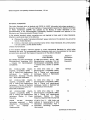
Electromagnetic Compatibility Sectional Committee, LTD 22
NATIONAL
FOREWORD
This Indian Standard which is identical with CISPR 24 (1997) ‘Information technology equipment —
Immunity characteristics — Limits and methods of measurements’ issued by the Special Committee
on Radio Interference (CISPR) was adopted by the Bureau of Indian Standards on the
recommendation of the Electromagnetic Compatibility Sectional Committee and approval of the
Electronics and Telecommunication Division Council.
,,
In the adopted standard, certain conventions are not identical to those used in Indian Standards.
Attention is particularly drawn to the following:
a)
Wherever the words ‘International Standard’ appear referring to this standard, they should be
read as ‘Indian Standard’.
b)
Comma (,) has been used as a decimal marker while in Indian Standards, the current practice
is to use a point (.) as the decimal marker.
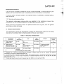
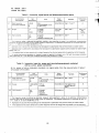
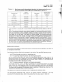
CROSS REFERENCES
In this adopted standard, reference appears to certain International Standards for which Indian
Standards also exist. The corresponding Indian Standards which are to be substituted in their place
are listed below along with their degree of equivalence for the editions indicated:
International
Standard
Degree of
Equivalence
Corresponding
Indian Standard
IEC 60050(161 ):1990 International
Electrotechnical Vocabulary (IEV)
— Chapter 161: Electromagnetic
compatibility
IS 1885 (Part 64/See 1 and 2) :1987
Electrotechnical vocabulary: Part 64
Electromagnetic compatibility, Section
1 General terms, Section 2 Specific
terms
Technically
Equivalent
IEC
Electro61000-4-2:1995
magnetic compatibility (EMC) —
Part 4: Testing and measurement
techniques
—
Section
2:
Electrostatic discharge immunity
test — Basic EMC Publication
IS 14700 (Part 4/See 2) : 1999
Electromagnetic compatibility (EMC):
Part 4 Testing and measurement
techniques, Section 2 Electrostatic
discharge immunity test
Identical
IEC
Electro61000-4-4:1995
magnetic compatibility (EMC) —
Part 4: Testing and measurement
techniques — Section 4: Electrical
fast transientiburst immunity test —
Basic EMC Publication
IS 14700 (Part 4/See 4) : 1999
Electromagnetic Compatibility (EMC):
Part 4 Testing and measurement
techniques, Section 4 Electrical fast
transienthurst immunity test
do
IEC
Electro61000-4-8:1993
magnetic compatibility (EMC) —
Part 4: Testing and measurement
Power
techniques
Section
8:
frequency
IS 14700 (Part 4/See 8) : 1999
Electromagnetic Compatibility (EMC):
Part 4 Testing and measurement
Power
techniques,
Section
8
frequency magnetic field immunity test
do
CISPR
22:1997
Information
technology equipment — Radio
disturbance
characteristics
—
Limits
methods
of
and
measurements
IS 6873 (Part 7) : 1!299 Limits and
methods of measurements of radio
disturbance charactersitcs: Pari 7
Information
technology
equipment
(first revision)
do
.
.
(Continued
on third cove~
*’A
Is
15039:2001
CISPR
24(1997)
CONTENTS
Page
3
1
Scope and object ............ .................. .. ......... ... .............. ..................... .... ........ ...... ..... ..
2
Normative
references .......... .................... ....... ............. ....... .......... ... ...... .............. ..... ...
3
Definitions
.... ................... ......... ................. ..... .............. .. .... ............... ..................... ... .
4
Immunity test requirements
5
Applicability
. ........ .......... .. .. ....... ................. .... ............ ....... .... ........ ..... .... .. .......... ... ..... .
9
6
Conditions during testing .... ....... ............ ...... ... .... ... .... ...... ..... ............... ..................... ..
9
7
Performance
critetia ..................................................................................................................
10
8
Product documentation ......................................................................................................... .....
11
....... .... .. ......... ..... ............... .. ..... .............. ....... ................ ...
“3
4
6
Tables
Immunity, enclosure
2
Immunity, signal ports and telecommunication
ports ..... ...... ............... ..... .............. ..... ..
12
3
Immunity, input d.c. power port (excluding equipment marketed
with an a.c./d.c. power converter) .......... ...... ....... ....... ....... .... ... ...... ....... .......... .. ........ ...
12
Immunity, input a.c. power port (including equipment marketed
with aseparatea.c./d.c.
power converter) .................................................................................
13
4
port ...... ....... ..... ....... ...... ... ........... ....... ... ........ ....... ..................... ...
11
1
. ..---”
Annexes
equipment ...... .... ........ ..... .. .... ........ ......... .... ......... ... .......
14
equipment .. ................ ........ ..... .............. .... .. .............. .... ........ ...... ..... .
21
A Telecommunications
B Data processing
terminal
(LAN) ....... .................... ..... ......... ....... .................. .... ........ ......... ...
25
D Printers ........ ..... .................. .............. .. ........ ..... ........... ....... ............... ..... .................... .
26
E Copying machines ........ ....... ................ ........... ............. ....... ............... ....... ............ .......
27
F
(ATM) .......... ........ ... .................. ............ .. ...... ..................... .
28
G Point of sale terminals (POST) ...................................................................................................
30
C Local area networks
Automatic teller machines
1
)
I
.
As in the Original Standard, this Page is Intentionally Left Blank
—
,J
.“6<
,
Is
15039
CISPR
24
2001
1997)
,,’
lndian Standard
INFORMATION TECHNOLOGY EQUIPMENT —
IMMUNITY CHARACTERISTICS — LIMITS AND
METHODS OF MEASUREMENT
1
Scope
and object
This CISPR
CISPR 22.
publication
applies
to information
technology
equipment
(ITE)
Procedures
are defined for the measurement
of ITE and limits are
developed for ITE and within the frequency range from O Hz to 400 GHz.
as
specified
defined
which
The object of this publication is to establish requirements which will provide an adequate
of intrinsic immunity so that the equipment will operate as intended in its environment.
For exceptional
environmental
conditions,
special mitigation measures
in
,
;
are
~
!
level
..,
may be required.
Owing to testing and performance
assessment
considerations,
some tests are specified in
defined frequency bands or at selected frequencies.
Equipment which fulfils the requirements
at these frequencies is deemed to fulfil the requirements in the entire frequency range from
O Hz to 400 GHz for electromagnetic
phenomena.
The object of this publication is to define the immunity test requirements for equipment defined
in the scope in relation to continuous and transient, conducted and radiated disturbances,
including electrostatic discharges (ESD).
The test requirements
1
Safety
are specified for each port considered.
considerations
are not covered
. ..-
in this publication.
i
2
In special cases, situations
will arise where the level of disturbance
may exceed the levels specified
in this
publication,
for example where a hand-held
transmitter
is used in proximity to an equipment.
In these instances
special mitigation
measures
may have to be employed.
2
Normative
references
The following normative documents contain provisions which, through reference in this text,
constitute
provisions
of this international
Standard.
For dated references,
subsequent
amendments
to, or revisions of, any of these publications do not apply. However, parties to
agreements based on this International Standard are encouraged to investigate the possibility
of applying the most recent editions of the normative documents indicated below. For undated
references, the latest edition of the publication referred to applies. Members of ISO and IEC
maintain registers of currently valid International Standards.
“
IEC 60050(161):
1990,
/r?ternationa/
Electromagnetic
compatibility
IEC 60318:1970,
An /EC artificia/
used in audiometry
E/ectrotechnica/
ear, of the widebar?d
3
Vocabulary
type,
(IEV)
-
for the calibration
Chapter
161:
of earphones
7
●’4%
Is
15039:2001
CISPR
24 (1997)
IEC 61000-4-2:1995,
techniques – Section
IEC 61000-4-3:1995,
techniques – Section
EMC Publication
Electromagnetic compatibility (EMC) – Part 4: Testing and measurement
2: Electrostatic
discharge immunity test – Basic EMC Publication
Electromagnetic
compatibility
3: Radiated, radio-frequency,
(EMC) – Part 4: Testing and measurement
electromagnetic
field immunity test – Basic
IEC 61000-4-4:
1995, Electromagnetic
compatibility
techniques – Section 4: Electrical fast transient/burst
(EMC) – Part 4: Testing and measurement
immunity test – Basic EMC Publication
IEC 61000-4-5:1995,
techniques – Section
Electromagnetic
compatibility
(EMC) – Part 4: Testing
5: Surge immunity tests - Basic EMC Standard
and measurement
IEC 61000-4-6:1996,
techniques – Section
Electromagnetic
compatibility
(EMC) – Part 4: Testing and measurement
6: Immunity to conducted disturbances,
induced by radio-frequency
fields
IEC 61000-4-8:1993,
techniques – Section
Electromagnetic
compatibility
(EMC) – Part 4: Testing and measurement
8: Power frequency magnetic field immunity test
IEC 61000-4-11:
1994, Electromagnetic
compatibility
(EMC)
Part
4:
Testing
and
measurement
techniques
– Section 11 .“ Voltage dips, short interruptions
and voltage variations
immunity tests
CISPR 22: 1997, /formation
technology
Limits and methods of measurement
equipment
ISO 9241-3: 1992, Ergonomic requirements
Part 3: Visual display requirements
for office work with visual display
ITU-T
Recommendation
ITU-T Recommendation
interfaces
– Radio
characteristics
disturbance
terminals
(VDTS) -
1.241.1: Te/ephony
1.411:
/ntegrated
service
digital
network
(/SDN)
user
network
-----
IT U -T Recoin mend at ion K. 15: Protection
overvoltage
and HF-disturbances
of
high
capacity
transmission
systems
ITU-T Recommendation
K.17: Tests on power fed repeaters using solid state
to check the arrangements
for protection
from external interferences
IT U-T Recoin mendation K.20:
overvoltage
and overcurrents
Resistibility
of
ITU-T Recommendation
overcurrents
Resistibility
of
K.21:
telecommunication
subscribers’
devices
switching
terminals
IT U-T Recommendation
K.22: Overvoltage resistibility of equipment
bus, Blue Book, Volume IX, November 1988
3
–
to
in order
equipment
overvoltage
connected
against
to
and
to an LSDN T/S
Definitions
For the purpose of this publication, the definitions contained in the following documents apply:
ITU-T Recommendation
1.411, IEC 60050 (161), International
Electrotechnical
Vocabulary
(IEV), Chapter 161. In addition, the following specific definitions apply:
3.1
continuous
wave (CW): Electromagnetic waves, the successive oscillations of which are
sinusoidal and identical under steady-state conditions, which can be interrupted or modulated
to convey information.
-
Is
CISPR
“--i
-
15039:2001
...
:,.
24(1997)
4’ .
.
3.2
degradation:
The unwanted change in operational
electromagnetic
disturbances.
This does not necessarily
failure.
performance
of an EUT due to
mean malfunction or catastrophic
:r
‘i
,.
,,”
3.3
equipment
under
ITE (that is a system)
purposes.
“;:
:!
test (EUT): A representative
ITE or functionally interactive group of
which includes one or more host units and is used for evaluation
,’
3.4
information
CISPR 22.
technology
equipment
(ITE):
The
definition
of ITE
is as described
{
3.5 jitter (of a cathode ray tube (CRT) monitor):
Peak-to-peak
variation
location of picture elements on the viewing surface of the CRT monitor.
3.6 temporal
luminance.
in
instability
(flicker):
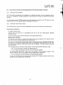
3.7
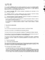
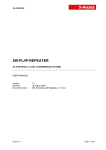
port: Particular interface
environment (see figure 1).
The
perception
of the specified
Enclosure
DC power
port
AC power
port
of
unintended
equipment
in the geometric
temporal
with the external
electromagnetic
Earth port
Signal
port
Telecommunication
1-
in
port
Information
technology
equipment
Figure
variation
Description
port
of ports
-----
3.8 enclosure
port: The physical boundary of the equipment through which electromagnetic
fields may radiate or impinge. For plug-in units, the physical boundary will be defined by the
host unit.
3.9 cable port: A point at which a conductor
Examples are signal and power ports.
or a cable
is connected
.
to the equipment.
3.10
a telephony
call: The process exercised in the network and the telecommunication
terminal equipment (TTE) to allow interchange of information (speech, video or data) with
another TTE through the network.
NOTE – The call shall be operated
in the way specified
by the manufacturer.
For circuit switched
services the
exchange of data shall be considered
to be possible when a 64 kbit/s channel or equivalent
is available
for both
parties. For packet service the exchange of information
shall be considered
to be possible when a virtual path is
established
to the called TTE.
3.11
to establish
a telephony
call: The operating procedure for a user or an automatic
process in conjunction with the network to reach the capability to exchange information with
another TTE. See note to 3.10.
3.12
to receive
a telephony
call: The operating procedure for a user or an automatic
process initiated by, and in conjunction with, the network to reach the capability to exchange
information with another TTE. See note to 3.10.
I
3.13
to maintain a telephony
call: The capability
to clear and re-establish a call. See note to 3.10.
i
of exchanging
information
without having
5
/
(
.
IS
15039:2001
CISPR
(.
24(1997)
‘;
&--
3.14
to clear a telephony
call: The operating procedure for a user or an automatic process
in conjunction with the network (either at the initiative of the local party or the distant party) to
stop the capability of exchanging
information by an orderly return to a state where the
establishment of a new call is possible. See note to 3.10.
3.15
network
terminator
telecommunication
network.
(NT):
Ancillary
equipment
representing
the
termination
k.
#J”:.
i
of the
.s
3.16
telephony
service:
A service providing users with the ability for real-time
speech conversation via a network (see ITU-T Recommendation
1.241 .1).
3.17
telecommunications
terminal
equipment:
Equipment
public or private telecommunications
network, that is:
a) to be connected directly to the termination
send, process or receive information; or
b) to interwork
the
with
of
termination
a telecommunications
a telecommunications
intended
to be connected
of a telecommunications
network
network
two-way
network
being
connected
directly
or
in order
to send,
process
j>
i
to a
in order to
indirectly
to
or receive
information.
i
4
Immunity
4.1
test requirements
General
The immunity test requirements
Tests shall be conducted
for equipment
in a well-defined
are given on a port-by-port
and reproducible
The tests shall be carried out as single tests in sequence.
basis.
manner.
The sequence
of testing is optional.
The description of the test, the test generator, the test methods and the test set-up are given in
IEC basic EMC standards which are referred to in the following tables.
The contents of these IEC basic EMC standards are not repeated here; however, modifications
or additional information needed for the practical application of the tests are given in this
publication.
4.2
Particular
4.2.1
requirements
Electrostatic
discharges
(ESD)
Static electricity discharges shall be applied only to those points and surfaces of the EUT which
are expected to be touched during usual operation, including user access, as specified in the
user manual, for example for ribbon and paper roll changes.
The discharges
shall be applied in two ways:
a) contact discharges
to the conductive
surfaces and to coupling planes:
The EUT shall be exposed to at least 200 discharges, 100 each at negative and positive
polarity, at a minimum of four test points (a minimum of 50 discharges at each point). One
of the test points shall be subjected to at least 50 indirect discharges (cotitact) to the centre
of the front edge of the horizontal coupling piane.The remaining three test points shall each
6
/, >.-
f’
Is 15039:2001
CISPR 24(1997)
receive at least 50 direct contact discharges, If no direct contact test points are available, then
at least 200 indirect discharges shall be applied in the indirect mode (see IEC 61000-4-2 for
use of the Vertical Conducting Plane (VCP)). Tests shall be performed at a maximum
repetition rate of one discharge per second.
b) air discharge
at slots and apertures,
and insulating surfaces:
On those parts of the EUT where it is not possible to perform contact discharge testing, the
equipment should be investigated to identify user accessible points where breakdown may
occur; examples
are openings at edges of keys, or in the covers of keyboards and
telephone handsets. Such points are tested using the air discharge method. See also
IEC 61000-4-2
regarding painted surfaces. This investigation should be restricted to those
areas normally handled by the user. A minimum of 10 single air discharges shall be applied
to the selected test point for each such area.
The application of electrostatic
required by this publication.
4.2.2
Electrical
fast transients
discharges
contacts
of open
connectors
is not
(EFT)
The test method is given in IEC 61000-4-4.
is not applicable for ITE.
The test procedure
clarifications:
to the
and
multiconductor cables, such as a 50-pair telecommunication
cable, shall be tested
single cable. Cables shall not be split or divided into groups of conductors for this test;
as a
if the equipment
in IEC 61000-4-4
the test set-up for in situ measurements
changes
.
is as given
However,
together
contains identical ports, only one shall be tested;
interface ports, which are intended by the manufacturer
not longer than 3 m, shall not be tested.
4.2.3
continuous
with the following
radio frequency
to be connected
to data cables
disturbances
.
The preferred frequency range for the radiated field test is 80 MHz to 1 000 MHz.
frequency range for the continuous conducted test is 0,15 MHz to 80 MHz.
radiated test may be performed with a start frequency lower than 80. MHz; in
continuous conducted test (where applicable)
need only be carried out up
frequency.
The preferred
However, the
that case the
to this start
The frequency ranges are scanned as specified; however, at a limited number of selected
frequencies
a more comprehensive
functional test may be required. The requirement
to
undertake this additional selected frequency test is not universally applicable to all products,
but only to products which have this requirement specified in annex A (under particular product
specific requirements). The selected frequencies are given in tables 1 to 4.
The dwell time at each frequency shall not be less than the time necessary for the EUT to be
exercised and to be able to respond; however, the dwell time shall not exceed 5 s at each of
the frequencies during the scan.
The time to exercise the EUT shall not be interpreted as a total time of a programme
but related to the reaction time in case of failure of the EUT.
7
or a cycle
‘.”
Is
—
15039:2001
CISPR
4.2.3.1
$+
24(1997)
Continuous
radiated
..—
disturbance.$
,The test procedure
is in accordance
with IEC 61000-4-3.
,:.,
.’
,.
f,
The EUT shall
electromagnetic
investigated.
be positioned so that the four sides of the EUT shall be exposed to the
field in sequence.
In each position the performance
of the EUT will be
..,.
.’&
‘,
j
In the case where the most sensitive surface side of the EUT is known throughout the
frequency range (for example, via preliminary tests), testing may be restricted to that surface
side only.
In cases of dispute, testing on the four surface sides shall take precedence.
If the EUT is too large to be adequately
shall be used.
illuminated
by the radiating antenna
partial illumination
Partial illumination shall be carried out using one of the following techniques:
– the EUT can be repositioned so that the front surface remains separated
from the
radiating antenna by the test distance (perpendicular with the axis between the calibration
point and the radiating antenna) in order to illuminate those sections of the EUT outside the
previous antenna beam width;
– where the EUT consists of separate
within the antenna beam width.
modules,
the modules
can be tested
separately
In cases of dispute, full illumination of the EUT will take precedence.
The frequency range can be swept incrementally with a step size not exceeding
fundamental with a test level of twice the value of the specified test level.
4 % of the
In cases of dispute, testing with 1 % steps will take precedence.
4.2.3.2
Continuous
There shall
in 4.2.3.1).
4.2.4
conducted
disturbances
be no additional
Power-frequency
The test procedure
magnetic
deviations
from
IEC
61000-4-6
(other
than
those
specified
fields
shall be in accordance
with IEC 61000-4-8.
The EUT shall be arranged and connected to satisfy its functional
placed at the centre of the coil system (immersion method).
requirements,
and shall be
The cables supplied by the equipment manufacturer shall be used or, in their absence,
alternative cables of the type appropriate to the signals involved shall be used.
suitable
Physically large products need not be completely submerged in the magnetic field, only the
sensitive devices (such as CRT monitors if they are the only sensitive parts). In this case, and
if the CRT monitor is integral with the ITE, then the CRT monitor or sensitive device can be
removed for testing.
4.2.5
Surges
The test procedure
K21 or K22.
shall be in accordance
with IEC 61000-4-5
8
or, if appropriate,
ITU-T
K20,
;
Is
15039:2001
CISPR
4.2.6
Voltage
dips and interruptions
The test procedure
that standard,
5
24(1997)
is in accordance
with IEC 61000-4-11.
There
shall be no deviations
from
Applicability
Tests shall be applied to the relevant ports of the equipment
shall only be carried out where the relevant port exists.
according
to tables
1 to 4, Tests
1
I ;,
It may be determined
from consideration
of the electrical characteristics
and usage of a
particular equipment that some of the tests are inappropriate and therefore unnecessary.
In
such a case, it is required that both the decision and the justification not to apply any particular
test to any particular port be recorded in the test report.
6
Conditions
6.1
Genera/
during
testing
d
/
j
?
conditions
The tests shall be made exercising all primary functions in the most representative
mode
consistent with typical applications. The test sample shall be configured in a manner consistent
with typical installation practice.
If
the equipment
equipment
shall
is
be
auxiliary equipment
CISPR 22.
part
tested
of
a
system
while
necessary
or
connected
to exercise
can
be
to
connected
the
minimum
to
auxiliary
representative
the ports in a similar
manner
equipment,
then
the
configuration
of
to that described
in
The configuration and mode of operating during the tests shall be precisely noted in the test
report. It is not always possible to test every function of the apparatus; in such cases, the most
critical mode of operation shall be selected.
If the equipment either has a large number of terminals or a large number of ports with similar
connections,
then a sufficient number shall be selected to simulate the actual operating
conditions and to ensure that all the different types of termination are covered.
Coil cables (such as keyboard cables) shall not be intentionally stretched during testing.
such cables, the length specified in the table notes refers to unstretched conditions.
The test equipment or auxiliary equipment (for example
shall not have any influence on the result of the testing.
NT or simulator)
connected
For
to the EUT
In cases where a manufacturer’s
specification
requires external
protection
devices
or
measures which are clearly specified in the user’s manual, then the test requirements of this
standard shall be applied with the external protection devices or measures in place.
During testing, the environmental
conditions and supply voltages shall remain within
operating ranges specified for the product unless otherwise indicated in the basic standard.
the
If an earth connection independent of the power supply cable is provided, this earth connection
shall be installed according to the specifications
of the manufacturer for the tests (given in
tables 1 to 4) at all other ports.
9
//
J
,.
-
Is
15039:2001
CISPR
6.2
24(1997)
Particular
conditions
(EUT operational
The particular conditions specified
parts of the general conditions,
in the annexes
Where particular conditions for specific
general conditions shall apply.
7
Performance
modes,
functions
etc.)
take
precedence
are not given
over the corresponding
in this standard,
then the
criteria
The manufacturer has the obligation to express the performance criteria in terms which relate
to the performance of his specific product when used as intended.
The following performance
criteria are
functions referred to are implemented.
7.1
General
performance
applicable,
operational
tests of all peripheral
–
quality of software execution;
-
quality of data display and transmission;
–
quality of speech transmission.
criterion
only be evaluated
when
the
to be evaluated
during testing include, but
modes and states;
–
Performance
shall
criteria
Examples of functions defined by the manufacturer
are not limited to, the following:
— essential
and
access (hard disks, floppy disks, printers, keyboard,
mouse, etc.);
A
The equipment
shall continue to operate as intended without operator intervention.
No
degradation of performance or loss of function is allowed below a performance level specified
by the manufacturer when the equipment is used as intended, The performance level may be
replaced by a permissible
loss of performance:
If the minimum performance
level or the
permissible performance loss is not specified by the manufacturer, then either of these may be
derived from the product description and documentation, and by what the user may reasonably
expect from the equipment if used as intended.
Performance
criterion
B
After the test, the equipment
shall continue to operate
as intended without operator
intervention. No degradation of performance or loss of function is allowed, after the application
of the phenomena
below a performance
level specified by the manufacturer,
when the
equipment is used as intended. The performance level may be replaced by a permissible loss
of performance.
During the test, degradation of performance is allowed.
or stored data is allowed to persist after the test.
However,
no change of operating
state
If the minimum performance level (or the permissible performance loss) is not specified by the
manufacturer,
then either of these may be derived from the product description
and
documentation,
and by what the user may reasonably expect from the equipment if used as
intended.
10
&
--—Is
15039:2001
CISPR
24(1997)
-–—d
.
Performance
criterion
C
Loss of function is allowed, provided the function is self-recoverable,
or can be restored by the
operation of the controls by the user in accordance with the manufacturer’s
instructions,
~.,
!’,
“k
Functions, and/or information
shall not be lost.
stored in non-volatile
memory,
or protected
by a battery backup,
{
7.2
Particular
performance
criteria
The particular performance
criteria which are specified
in the
precedence over the corresponding parts of the general performance
Where particular performance criteria
performance criteria shall apply.
8
Product
,!
for specific
functions
normative
criteria.
annexes
take
are not given, then the general
documentation
The specification used by the manufacturer to define the performance criteria for the testing
required by this standard shall be made available to the user upon request.
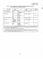
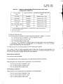
Table
1-
Immunity,
enclosure
Espe’’’ionon
1.1
Power-frequency
magnetic field
50 or 60
1
Hz
A/m (r.m.s.)
1.2
Radio-frequency
electromagnetic
field
Amplitude modulated
s80-I
3
81J
MHz
V/m (unmodulated,
% AM (1 kHz)
Electrostatic
4 (Contact
discharge)
kV (charge voltage)
8 (Air discharge)
kV (charge voltage)
1.3
1) Applicable
electrodynamics
2)
The
frequency
discharge
only t. equipment
c..tai.ing
devices susceptible
microphones,
magnetic field sensors, etc.
range
is
scanned
test shall be carried out at a limited
863 and 900 MHz (*1 %).
3)
The test may be perforr.
as
specified.
number
ed with a .tarf
However,
of frequencies.
frequency
I
Basic
standard
Units
000
port
Remarks
IEC 61000-4-8
See 1J
IEC 61000-4-3
The test level specified
is prior to modulation
See 2, and 3,
r.m.s)
Performance
criterion
A
See annex B
to magnetic
fields,
in annex
The selected
frequencies
----
A
B
IEC 61000-4-2
Whe. specified
such
as CRT
A, a. additional
monitors,
Hall
comprehensive
elements,
functional
are: 80, 120, 160, 230, 434, 460,
lower than 80 Mhz, but not less than 26 MHz.
11
I
600,
“;’ &
Is
15039:2001
CISPR
24(1997)
Table
2-
Enwronmental
phenomenon
‘.1
Immunity,
signal
ports and telecommunication
Test
specification
0,15-80
3
80
Mi+z
V (unmodulated,
% AM (1 kHz)
!.2
Surges
1,5
4
1 0/700
~~
Fast transients
0,5
5/50
5
1)
The frequencY
range
is scanned
Applicable
only to ports which according
s) Applicable
only to cables
greater than 3 m.
3)
kV (peak)
kV (peak)
Tr/Th ps
ITU-T Rec.
K series
See’1
and 5,
kV (peak)
TrlTh ns
Repetition
IEC 61000-4-4
See 3,
4,
If the radiated
test has been carried
r.m.s.)
frequency
However,
when
specified
of frequencies.
in annex
The selected
specification
to the manufacturer’s
out to a lower frequency
See ITU-T
Rec.
K series
B
kHz
to the manufacturer’s
which according
A
and 4,
See l),
as specified.
Performance
criterion
Remarks
IEC 61000-4-6
functional
test shall be carried out at a limited number
0,2; 1; 7,1; 13,56; 21; 27,12 and 40,68 MHz (*1 ?’.).
2J
Basic
standard
Units
Radio-frequency
continuous conducted
ports
specification
A, an additional
frequencies
may connect
supports
comprehensive
for conducted
directly
to outdoor
communication
then the test range shall only extend
3-
Immunity, input d.c. power port (excluding
with a a.c./d.c. power converter)
d.c. power is fed on conductors
only apply to this cable)
up to this frequency.
Test
specification
Tr/Th IJS
kv (peak)
i EC 61000-4-5
Test applied lines
&eziJh (ground)
kV (peak)
Tr/lh ns
Repetition
frequency kHz
IEC 61000-4-4
MHz
V (unmodulated,
% AM (1 kHz)
).2
Surges
1,2/50 (8/20)
0,5
13
Fast transients
0,5
5/50
5
1) The frequencY
range
is scanned
as specified,
functional
test shall be carried out at a limited
1; 7,1; 13,56; 21; 27,12 and 40,68 MHz (*1 Y.).
only to ports which according
2)
Applicable
s)
If the radiated
test has been carried
number
However,
out to a lower frequency
12
3)
r.rn.s.)
when
of frequencies.
to the manufacturer’s
Performance
criterion
A
See 1) and
0,15-80
3
80
of table 2
Remarks
IEC 61000-4-6
Radio-frequency
continuous COIhcted
1.1
Basic
standard
Units
protectors
marketed
included in a signal cable, then the requirements
(if
Environmental
phenomenon
equipment
cables.
on cable lengths
SJ For ports where primary protection
is intended, surges are applied at voltages up to 4 kV with the primary
fitted. Otherwise
the 1,5 kV best level is applied without primary protection
in place.
Table
tests are:
specified
in annex
The selected
specification
B
B
A, an additional
frequencies
may connect
comprehensive
for conducted
directly
then the test range shall only extend
to outdoor
test are: 0,2;
cables.
up to this frequency.
—..’6<
-.. --- A
Is
15039:2001
CISPR
24(1997)
..—
Table
4-
Immunity,
input a.c. power ports (including
with a separate a,c./d.c power converter)
Environmental
phenomenon
$.1
4.2
Teet
specification
Radio-frequency
continuous conducted
0,15-80
3
80
Voltage
>95
0,5
dips
equipment
Basic
standard
Units
MHz
V (unmodulated,
Y. AM (1 kHz)
marketed
Remarks
IEC 61000-4-6
See 1Jand ~
A
IEC61OOO411
See z)
B
r.m.s)
reduction
period
7.
c
reduction
periods
30
25
Performance
criterion
%!.
>95
250
‘h reduction
periods
IEC 61000-4-11
See p)
c
Surges
1,2/50 (8/20)
1 line to line
2 line to earth
(ground)
Tr/Th I.IS
kV (peak)
kV (peak)
IEC 61000-4-5
See
B
Fast transients
1,0
5150
5
kV (peak)
Tr/Th ns
Repetition
frequency kHz
IEC 61000-4-4
4.3
Voltage
$.4
$.5
interruptions
4)
B
1) The frequency
range is scanned
as specified.
However,
when specified
in annex A, an additional
comprehensive
functional
test shall be carried out at a limited number of frequencies.
The selected frequencies
for conducted test are:
0,2; 1; 7,1; 13,56; 21; 27,12 and 40,66 MHz (*1 %).
z)
Changes
to occur at O degree
3)
If the radiated
crossover
test has been carried
point of the voltage
out to a lower frequency
VJavefOrm.
then the test range shall only emend Up to this frequency.
4) When the manufacturer
specifies
protection
measures
and it is impractical
tests, then the applied test levels shall be reduced to 0,5 kV and 1 kV.
13
/
to simulate
these
measures
during
the
..-..
.
—“
Is
15039
CISPR
:2001
(
24(1997)
.
,..
—
j
A
Annex
(normative)
7
‘$.
,.,,, ,
r
Telecommunications
terminal
equipment
‘.
...
,
!,
y
A.1
Telecommunications
terminal
equipment
(TTE) having an anaiogue
interface
{
‘
A. 1.1
Particular
test conditions
The telecommunications
terminal equipment (TTE) shall be configured for connection
telecommunication
line (or reference line) at its nominal impedance. Auxiliary equipment
the telecommunications
network.
be used to simulate
A. 1.2
Particular
performance
The following performance
Performance
criterion
a) Swept frequency
to a
may
criteria
criteria are applicable
only when the functions are implemented.
A
test
Testing shall be carried
described below.
out in accordance
with one of the two measurement
methods
In case of dispute, tests shall be carried out as originally performed.
Measurement
method
1
The volume control (where it exists) shall be set as close as possible to the position which
gives the nominal value as stated by the manufacturer.
The acoustic sound pressure level (spl) shall be measured using a calibrated artificial ear,
as defined in IEC 60318, coupled without loss to the acoustic receiving device of the TTE.
The background acoustic noise shall be less than 40 dB(spl). The audio channel shall be
open and active.
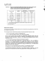
The following shall be fulfilled during a sweep in the whole specified frequency
–
the TTE shall be able to maintain an established
— for TTE supporting telephony
range:
call;
service, the following also applies:
the demodulated
narrowband
1 kHz (maximum
measurement
bandwidth of 100 Hz)
differential mode signal measured on the telecommunications
port shall not be greater
than the values given in table A.1, measured at the TTE nominal impedance (as specified
by the manufacturer);
–
for TTE having an acoustic interface,
the following also applies:
the acoustic demodulated sound pressure
greater than the values gwen in table A.1.
14
level (spl) in the receive
direction shall not be
.-
Is
CISPR
Table
A.1 -
Maximum acoustic
and at the acoustic
Frequency
I
band
I
Noise
(MHz)
I
signal
Acoustic sound
pressure level
(dB(s@))
Conducted
–50
55
30 to 40,66
Conducted
–30
75
40,66 to 40,70
Conducted
–50
55
Conducted
–30
75
40,70
80 to 1000
to 80
(except
at 900’)
I
-30
I
Radiated
900’
requirement
Radiated
is not applicable
for countries
75
I
55
–50
where
no digital
mobile
<
port
(dBm)
o,15t030
‘ This
exist.
24 (1997)
demodulated
levels at the telecommunications
receiving device (measurement
method 1)
Type of
immunity test
.!
15039:2001
services
operating
at 900 MHz
NOTEThese tests are designed to ensure a minimum
acceptable
immunity to amplitude
modulated
radiofrequency
disturbances
for devices
having acoustic
interfaces.
The demodulated
disturbance
levels are
higher than those that will be found acceptable
in practice,
The levels in the tests have been chosen for
their practical
test convenience,
having regard for the maximum
allowed background
acoustic
noise level
of 40 dB(spl)
and the test levels
to be applied
for functional
testing.
The amplitude
demodulated
disturbances
will arise, almost invariably,
from semi-conductor
junctions
behaving
as inadvertent
square
law detectors,
This means that for every 1 dB change in the level of the applied radio-frequency
signal the
demodulated
level will change by 2 dB, Therefore,
if a radiated immunity test subjecting
the EUT to a test
field carrier
level of 3 V/m produces
a resultant
demodulated
acoustic
1 kHz disturbance
output
of
55 dB(spl)
(a distinctly
annoying
acoustic
level for most listeners
with normal hearing,
but conveniently
above the allowed
background
noise level of 40 dB(spl)),
the test ensures that an amplitude
modulated
disturbance
field of 1 V/m (approximately
10 dB lower field strength)
applied to the same equipment
in a
real world situation
can produce
a demodulated
acoustic
disturbance
level of approximately
35 dB(spl),
which most people in a practical listening environment
do not perceive as annoying.
,. .- --.
Measurement
method
2
The volume control (where it exists) shall be set at a fixed level during calibration
be changed during the test.
and shall not
The following shall be fulfilled during a sweep in the whole of the specified frequency
— the TTE shall be able to maintain an established
–
for TTE supporting
telephony
range:
call;
service, the following also applies:
with the audio channel open and active, the demodulated differential mode noise on the
telecommunications
port measured at the TTE nominal impedance (as specified by the
manufacturer),
shall not be greater than the values given in table A.1. The measurement
bandwidth shall be 100 Hz maximum at 1 kHz;
–
for TTE having an acoustic interface,
the following also applies:
a sinusoidal signal of 1 kHz, –40 dBm is impressed on the telecommunication
line (signal
level without the radio-frequency
field). The resulting acoustic sound level is measured
using a microphone. The measured level shall be used and recorded as the reference level.
The signal used to establish the reference level is switched off during the actual test. The
measurement bandwidth shall be 100 Hz maximum.
The background
noise shall not exceed a level 15 dB below the reference
level.
The demodulated
differential
mode noise in the receive direction, measured
in the
described for the reference level, shall not be greater than the values given in table A.2.
1
15
way
Is 15039:2001
CISPR 24(1997)
Table
A,2 –
Maximum demodulated
differential
mode noise levels
telecommunications
port (measurement
method 2)
at the
1
Frequency
Type of
immunity test
band
(MHz)
o,15t030
I
40,70
I80to1000
I
mode
Reference
level -10
Reference
level +10 dB
Conducted
Reference
level -10
to 80
Conducted
Reference
level +1 O dB
Reference
level +lOdB
Reference
level –1 O dB
(except at 900’)
I
See note to table
Radiated
I
Radiated
●
This requirement
at 900 MHz exist.
is not applicable
for countries
noise
dB
to 40,70
900’
b) Se/ected
I
Conducted
differential
(dBm)
Conducted
30 to 40,66
40,66
Demodulated
where
no digital
mobile
dB
services
operating
Al.
frequency
test
The following shall be fulfilled at the spot frequencies specified in tables 1, 2, 3 and 4 (this
may be shown by checking the data sent to the line, to avoid having an operator in the field):
–
the TTE shall be able to establish a call with telephony service;
–
the TTE shall be able to receive a call;
–
the TTE shall be able to clear a call;
— where the TTE is intended to provide a data (non-telephony) service, the time required
for a transmission shall not, as a consequence of the application of the test, increase
beyond that defined by the manufacturer.
Performance
criterion
B
The following shall be fulfilled:
A call established
Requirements
prior to the application
of the disturbance
to be checked
–
after the application
.
the TTE shall be able to establish a call;
–
the TTE shall be able to receive a call;
–
the TTE shall be able to clear a call.
Performance
criterion
Requirements
to be checked
shall be maintained.
of the disturbance:
C
after the application
–
the TTE shall be able to establish a call;
–
the TTE shall be able to receive a call;
–
the TTE shall be able to clear a call.
of the disturbance:
16
I
----+
IS
15039:2001
CISPR
A.2
Telecommunications
A. 2.1
Particular
terminal
equipment
(TTE)
having
a digital
24(1997)
interface
test conditions
The TTE shall be configured for connection
its nominal impedance. Auxiliary equipment
network.
to a telecommunication
line (or reference line) at
may be used to simulate the telecommunications
For digital basic access, ISDN interfaces providing telephony service to the TTE shall be in idle
mode as defined for the applied digital to analogue conversion.
A.2.2
Particular
performance
The following performance
Performance
criterion
a) Swept frequency
criteria
criteria are applicable
only when the functions are implemented
A
test
Testing shall be carried
described below.
out in accordance
with one of the two measurement
methods
In case of dispute, tests shall be carried out as originally performed.
Measurement
method
1
The volume control (where it exists) shall be set as close as possible to the position which
gives the nominal value as stated by the manufacturer.
The acoustic sound pressure level (spl) shall be measured using a calibrated artificial ear,
as defined in IEC 60318, coupled without loss to the acoustic receiving device of the TTE.
The background acoustic noise shall be less than 40 dB(spl). The audio channel shall be
open and active.
The following shall be fulfilled during a sweep in the whole specified frequency
–
the TTE shall be able to maintain an established
–
for TTE supporting telephony service, the following also applies:
call;
the demodulated
differential mode noise and acoustic sound pressure
receive direction shall not be greater than the values given in table A.3;
–
for TTE having an acoustic interface,
range:
levels
in the
the following also applies:
the acoustic demodulated sound pressure
greater than the values given in table A.3.
17
level (spl) in the receive direction shall not be
.’6.
Is
15039:2001
CISPR
Table
24(1997)
A.3 -
Maximum demodulated
differential
mode noise and acoustic
pressure levels at the telecommunications
port and at the
acoustic receiving device (measurement
method 1)
Frequency
Type of
immunity
band
Demodulated
differential
mode
(MHz)
–50
55
30 to 40,66
Conducted
-30
75
40,66 to 40,70
Conducted
–50
55
80 to 1000
I
Conducted
\
-30
75
I
(except at 900”)
Radiated
-30
75
900”
Radiated
-50
55
‘ This requirement
is not applicable
operating at 900 MHz exist.
Measurement
(dB(spi))
Conducted
40,70 to 80
]s
Acoustic sound
pressure level
noise
(dBmO)
o,15t030
ee note to table
method
for countries
where
no digital
sound
mobile
services
A.1.
I
2
The volume control (where it exists) shall be set at a fixed level during calibration
be changed during the test.
The following shall be fulfilled during a sweep in the whole specified frequency
–
the TTE shall be able to maintain an established
–
for TTE supporting telephony service, the following also applies:
and shall not
range:
.. --
call;
with the audio channel open and active, the demodulated
differential mode noise and
acoustic sound pressure level from the EUT, measured in the assigned B–channel, shall not
be greater than the values given in table A.3. The measurement bandwidth shali be 100 Hz
maximum at 1 kHz;
–
for TTE having an acoustic interface the following also applies:
An A-law coded digital signal representing a sinusoidal signal of 1 kHz, –40 dBmO is
impressed
on the telecommunication
line (signal level without the radio frequency
disturbance). The resulting acoustic sound pressure level is measured using a microphone.
The measured level shall be used and recorded as the reference level. The signal used to
establish the reference level is switched off during the actual test. The measurement
bandwidth shall be 100 Hz maximum.
During the test, the idle code shall be sent to the EUT in the assigned
The background
B-channel.
noise shall not exceed a level 15 dB below the reference
level.
The demodulated
differential mode noise in the receive direction, measured in the way
described for the reference level, shall not be greater than the values given in table A.4.
18
1
I
*“A
——
.
Is
15039:2001
CISPR
Table
A.4 –
Frequency
Maximum demodulated
(measurement
method
Type of immunity
band
differential
2)
test
Demodulated
differential
Conducted
Reference
Conducted
Reference
level +1 O dB
to 40,70
Conducted
Reference
level –1 O dB
to 80
Conducted
Reference
level +1 O dB
(except at 900’)
Radiated
Reference
level +10 dB
900”
Radiated
Reference
level -10
30 to 40,66
40,70
‘ This requirement
I
operating
at 900
See
to table
b) Se/ected
note
noise
p;
!,
(dBm)
o,15t030
80 to 1000
mode
“i
)
,4
.!
.-
mode noise levels
(MHz)
40,66
24(1997)
is not applicable
MHz exist.
for countries
level -10
dB
,,
where
no digital
mobile
1
dB
services
~.
A.1.
t
frequency
test
The following shall be fulfilled at the spot frequencies
specifed
in tables 1, 2, 3 and 4:
{
— the TTE shall be able to establish a call with telephony service;
~
— the TTE shall be able to receive a call;
— the TTE shall be able to clear a call;
— where the TTE is intended to provide a data (non-voice) service, the time required for
a transmission
shall not, as a consequence
of the application of the test, increase
beyond that defined by the manufacturer.
For ISDN equipment
.
for primary access only the following also applies:
~
k
~.
The number of loss of frame alignments shall be less than 10 within a test period of 10
seconds, Where it can be clearly established that a voice call is maintained throughout the test
it is not then required to evaluate the loss of frame alignment.
Performance
criterion
B
The following shall be fulfilled:
A call established
Requirements
prior to the application
to be checked
of the phenomena
after the application
shall be maintained.
of the phenomena:
— the TTE shall be able to establish a ca!l;
— the TTE shall be able to receive a call;
— the TTE shall be able to clear a call.
Performance
criterion
C
Requirements
to be checked
after the application
— the TTE shall be able to establish a call;
— the TTE shall be able to receive a call;
— the TTE shall be able to clear a call.
19
of the phenomena:
;
Is
15039:2001
CISPR
A.3
24(1997)
Facsimile
A. 3.1
Particular
test conditions
The EUT shall be connected to a second EUT or simulator which permits a test pattern to be
sent to and be received from the EUT. A test pattern selected from the relevant ITU-T
recommendation
is preferred but is not mandatory. The following requirements are in addition
to the TTE performance requirements.
A.3.2
Particular
Performance
performance
criterion
criteria
A
The EUT shall operate normally during and after the test without:
–
data transfer errors, for example
-
degradation
no retries beyond the specified
of the printed image beyond the manufacturer’s
— missing text either full or partial, for example
–
unintended
re-initiating
Performance
specification;
letters;
line or page feed;
— colour change beyond the manufacturer-s
–
decapitated
maximum;
specification;
a call.
criterion
B
As for performance criteria A, with the following exceptions, which are permitted during the
application of the disturbance, provided that normal operation of the EUT is recoverable to the
condition immediately before the application of the disturbance:
-
degradation
–
unintended
Performance
of the printed image beyond the manufacturer’s
specification;
line feed.
criterion
C
Any degradation
of performance
is permitted,
provided that normal operation
is selfrecoverable, or can be restored after the test by the use Of operator controls, and provided
that:
–
any Interruptions
in the transmission
–
the EUT can re-establish
–
the EUT can receive a call;
–
the EUT can clear a call.
are logged and the user notified;
a call;
20
Is
15039:2001
CISPR
Annex
24(1997)
B
(normative)
Data
The
test
shall
functions
failure
of
be
carried
equipment
by display
or
out
using
and,
in
by operator’s
processing
an
case
exercising
of
equipment
program
failure,
enable
which
an
can
operator
repeat
to
the
recognise
sequences
the
nature
for
of
operation.
The test sequences
shall be selected from the following below according to the functions
defined by the manufacturer
of the equipment to be tested, and the performance criteria A,
B or C shall be selected according to the disturbance to be tested.
B.1
Read, write
and storage
Part/cu/ar
test conditions
B. 1.1
of data
Data read and write cycles shall be repeated with internal storage devices such as “semiconductor memories, magnetic or optical disks or magnetic tape devices, and then the copied
back data shall be compared with the original.
Read-only
data.
B. 1.2
memories
Particular
Performance
(ROM)
shall be read repeatedly
performance
criterion
criterion
with the expected
criteria
A
Storage devices shall maintain
Performance
and this data compared
normal operation both in read/write
and in stand-by conditions.
B
Failures which can be recovered by read and write retries are permissible
processing caused by this process is acceptable).
(temporary
delay in
Normal operation of the EUT shall be restored after the test, self-recovery to the conditions
immediately prior to the application of the test is accepted where this is a normal means of
recovery. In these cases, operator response is permitted to re-initialise an operation.
Performance
criterion
C
Failures resulting in a delay in processing after the external disturbance
can be recovered to normal operation by reset or reboot are permissible.
Failures
reboot
resulting
are
in a system
abort,
which
can
permissible.
21
be
recovered
to
normal
is removed,
operation
but which
by
reset
or
Is
15039:2001
CISPR
B.2
24(1997)
Data display
6.2,1
Particular
test conditions
Text or graphics shall be displayed on display devices such as CRT monitors
plasma
or LED displays,
B.2.2
Particular
Performance
performance
criterion
and
liquid
crystal,
criteria
A
When seen from the normal viewing distance, the EUT shall operate with no change beyond
the manufacturer’s
specification,
in flicker, colour, focus and jitter (except for the power
frequency magnetic field test).
Power
frequency
magnetic
field test
For CRT monitors, the following also applies:
The jitter shall be measured using a measuring microscope as specified in 6.6.14 of ISO 9241-3,
The jitter (in mm) shall not exceed the value
(character height in mm + 0,3) x 2,5
33,3
when the CRT monitor is immersed in a continuous
the power frequencies of 50 or 60 Hz.
magnetic
field of 1 A/m (r.m.s.)
at one of
Alternatively,
a field of 50 A/m may be applied, and a transparent graduated mask used to
assess the jitter. In that case, the jitter shall not exceed 50 times the value in the above
formula.
NOTE - This test
used if non-linearity
level is used to simplify
the measurement
of jitter. Lesser
is experienced,
due to, for example, saturation
of screening
The EUT shall be tested in two positions, both perpendicular
Performance
criterion
Screen disturbances
Performance
6.3.1
may
be
to the magnetic field.
of the test are permissible.
C
Failures which are not self-recovered
after removal of the external disturbance,
be recovered to normal operation by reset or reboot are permissible.
B.3
level
B
during the application
criterion
~alues of the test
material.
but which can
Data input
Particular
test conditions
Data shall be acquired with input devices such as keyboard, mouse, magnetic
optical character reader, image scanner, input pen or miscellaneous sensors.
Though continuous input is preferable,
testing in the stand-by
equipment which requires operator’s attendance for operation.
22
condition
card reader,
is permitted
for
.. . .
,
IS
15039:2001
CISPR
24(1997)
When the EUT is a mass data input device, such as a character reader or scanner, then the
central processing unit shall run a program which reads an appropriate test chart continuously
for the duration o~ the test. Read data-inputs are displayed, pinted directly, or stored for late-r
evaluation.
B. 3.2
Particular
Performance
Unintended
performance
criterion
criteria
A
input from input device is not allowed.
Input devices shall maintain the specified quality image data.
Performance
criterion
Keyboard/mouse
B
“lock up” is not allowed,
For equipment with manually inputted data which can be confirmed by reading the display,
errors which can be recognised by the operator and easily corrected are permissible.
Performance
criterion
C
Failures resulting in a delay in processing after the external disturbance
be recovered to normal operation by reset or reboot are permissible.
is removed,
but which
can
I
Failures resulting in a system
reboot are permissible.
B.4
B.4. 1
abort which can be recovered
operation
by reset or
‘1
Data printing
Particular
test conditions
Data shall be printed by printers or plotters. For equipment
test shall be selected in the most typical operation mode.
B.4.2
to normal
Particular
Performance
performance
criterion
criterion
A
printing quality and normal operation.
B
No degradation
of the printing quality beyond the manufacturer’s
distortion of character(s) or missing pixels) is permissible.
Performance
criterion
failure
specification
(such
as
C
Printing errors or omission of character(s)
Input/output
permissible.
modes,
criteria
Printers shall maintain the specified
Performance
which has several operation
which require reprinting are permissible.
which can be recovered
to normal
operation
by reset or reboot are also
23
I
I
I
,.
IS
15039:2001
CISPR
B.5
24(1997)
Data processing
6.5.1
Particular
test conditions
such as computation,
data conversion,
storage
or transfer
shall
Data processing,
performed, and the results of processing shall be compared with results in normal operation.
B.5.2
Particular
Performance
performance
criterion
Performance
criterion
Failures which
permissible.
Performance
Failures
be
A
within the product specification,
and
B
recovered
criterion
resulting
recovered
are
be
criteria
Failures which do not influence the specified operation
which do not prevent automatic recovery are permissible.
can
.“6+
automatically
but cause
temporary
delay
in processing
are
C
in a delay
to normal
in processing
operation
after
by reset
the
or
external
reboot
are
disturbance
Failures resulting in a system abort, which can be recovered
reboot are permissible.
Failures which are followed by alarms
operator’s intervention are permissible.
and can
is removed,
but
which
permissible.
to normal operation
be recovered
to normal
by reset or
operation
by the
..
24
*“A
Is
CISPR
Annex
“-’-4
15039:2001
24(1997)
C
(normative)
Local
C.1
Particular
A minimum
LAN
shall
system
transmission
consists
physical
included
manufacturer’s
The
configuration
specified
be
in the
of two
cable.
test
(LAN)
of terminal
equipment
equipment
configuration.
Unused
necessary
ports
shall
be
interconnected
to
treated
the
with
function
of
the
according
to
the
instructions.
shall
be
capable
of
delivering
and
receiving
data
at
the
specified
nominal
rate.
Particular
Performance
pieces
Associated
The LAN equipment executes a programme
the functions below shall be assessed.
C.2
networks
test conditions
test
manufacturer
area
performance
criterion
which exercises
the LAN functions. As a minimum,
criteria
A
During and after the test, the EUT shall operate without:
— error rate beyond the figure defined by the manufacturer;
— requests for retry beyond the figure defined by the manufacturer;
speed of data transmission
–
protocol failure;
–
loss of link.
Performance
criterion
rate beyond the figure defined by the manufacturer;
B
Error rate, request for retry and speed of data transmission
application of the test.
rate may be degraded
during the
Degradation of the performance as described in criteria A is permitted provided that the normal
operation of the EUT is self-recoverable
to the condition immediately before the application of
the test. In these cases, operator response is permitted to re-initiate an operation.
Performance
criterion
C
Degradation of the performance as described in criteria A and B is permitted provided that the
normal operation of the EUT is self-recoverable
to the condition- immediately
before the
application of the test or can be restored after the test by the operator.
25
,..
9’$%
Is
15039:2001
CISPR
24 (1997)
Annex
D
(normative)
Printers
D.1
Particular
test conditions
Data shall be printed
text containing more
Character pitch and
highest density shall
D,2
Particular
Performance
with printers or plotters. No standard image is required, but the use of a
than three character fonts and at least one grid of lines is recommended.
line spacing should be small. If the dot density can be selected, the
be chosen. Tests shall be carried out with the EUT in the printing mode.
performance
criterion
criteria
A
The EUT shall operate without degradation of performance
the disturbance. For example, there shall be no:
during and after the application
–
loss or corruption of data during input/output operations;
–
degradation
of the printed ima,ge beyond the manufacturer’s
change in output mode or character
–
perceptible
change in dot-pitch;
–
unintended
line or page feed.
Performance
criterion
As for performance
–
degradation
–
misalignment
–
unintended
of
specification;
font;
B
criterion A, with the following exceptions:
of the printed image beyond the manufacturer’s
specification
is allowed;
of the grid lines is allowed;
line feed is allowed.
After the disturbance
is removed, normal operation of the EUT is self-recoverable
to the
condition immediately before the application of the test; this may involve an operator response
to re-initiate the operation.
Performance
criterion
C
Degradation of the performance as described in criteria A and B is permitted provided that the
normal operation of the EUT is self-recoverable
to the condition immediately
before the
application of the test or can be restored after the test by the operator.
26
-
Is
15039:2001
CISPR
Annex
.’6,
24(1997)
E
(normative)
Copying
E.1
Particular
test conditions
No standard image is required,
of grey tones is recommended.
Testing shall be performed
E.2
Particular
Performance
machines
in the stand-by mode and the copying mode.
performance
criterion
but the use of a pattern consisting of a grid of lines and a scale
criteria
A
The EUT shall operate without degradation of performance
the disturbance. For example, there shall be no:
unintended
during and after the application
of
start of operation;
change of the program or of the program setting, for example:
●
single or double sided;
●
number of copies;
●
sorting and/or stapling;
●
contrast;
e
copy size, reduction or enlargement;
9
loss of stored or transmitted
-
interruption of copying sequence
–
false indications
–
fall back to stand-by
— unintended
-
(for example,
operation
degradation
.. -.--
data;
(for example,
paper jam);
paper jam, low toner, low paper, control indicators);
mode from copying mode;
of safety interlocks;
of copied images beyond manufacturer’s
specification;
— errors in billing devices.
Performance
criterion
As for performance
B
criterion A, with the following exception:
False indications of, for example,
permissible during the test.
paper
All false indications must be removed
completion of the test.
Performance
Degradation
qu~lifications
criterion
failures
no unintended
low toner,
low paper,
control
when the copier is reset to the stand-by
indicators
are
mode after the
C
of performance
and exceptions:
out’put/input
reboot;
jam,
as
specified
are only allowed
under
criteria
if normal
A is allowed,
operation
can be restored
start of copying from stand-by mode is allowed.
27
with
the
following
by reset or
-Is
15039:2001
CISPR
24(1997)
L.. —
Annex F
(normative)
Automatic
teller machines
(ATM)
t
\
F.1
Particular
test conditions
The ATM shall be connected to each
communication
line shall be connected
representative
individual
load.
equipment
Interconnecting
of its peripheral devices and one of each type of
driven into the correct terminating eaui ,–
Dment or a-.
cables
requirements.
One
shall
subassembly
be
of
a
of
each
basic operation shall be included in the ATM to be evaluated.
ITE that can be included in the possible system configuration
type
and
lengt~
specified
in
the
ITE necessary for the
For a system, one of each type of
shall be included with the ATM.
type
of
In the case of ATMs which functionally interact with other ITE, including any ITE that is
dependent on the ATM for its power interface, either the actual interfacing EUT or simulators
may be used to provide representative
operating conditions, provided the effects of the
simulator can be isolated or identified.
The ATM shall execute a program which shall exercise each function whose integrity is to be
assessed during the test. As a minimum, the functions noted below shall be assessed. Where
more than one function is to be assessed, the software shall be flexible enough to permit the
test operator to select certain functions if so desired. A parallel or serial execution of the test is
permitted provided that the ATM can operate in that manner. Ta facilitate the testing, the
software shall alert the operator when a failure has occurred.
The ATM shall be operated using the default settings upon start-up. The ATM shall be
evaluated in all modes unless the most susceptible mode is already known from preliminary
testing or previous experience, in which case the most susceptible mode shall be used.
F.2
Particular
Performance
performance
criterion
i
criteria
A
The EUT shall operate without degradation of performance
the disturbance. For example, there shall be no:
during and after the application
–
system response time beyond the figure defined by the manufacturer;
-
memory errors;
–
data corruption;
— repeated
self-recoverable
errors beyond a number specified by the manufacturer;
–
loss of stored data;
–
keyboard lock-up;
–
system reset or shut down;
.. -~
28
of
Is
15039:2001
CISPR
24(1997)
— system change state;
network connections
dropping;
— money or receipts inappropriately
dispensed;
— 1/0 errors;
— 1/0 state change.
Performance
criterion
B
There shall be no loss of stored data during the application of the disturbance. A transaction
may be aborted provided that this is correctly reported. There shall be no incorrect dispensing
of money or printed receipts.
Degradation
of the performance
as described in criterion A is permitted provided that the
normal operation of the EUT is setf-recoverable
to the condition immediately
before the
application
of the test. In these cases, operator response is permitted to re-initiate
an
operation.
Performance
criterion
C
There shall be no loss of function following the restoration of the system by the operator. Loss
or corruption of the contents of Random-Access
Memory (RAM) and information stored on
permanent storage media, such as hard drive, optical or floppy disk, is not permitted.
Degradation of the performance as described in criteria A and” B is permitted provided that the
normal operation of the EUT is self-recoverable,
or can be restored after the test by the
operator.
29
/!
IS
15039:2001
CISPR
24(1997)
Annex G
(normative)
Point
G.1
Particular
of sale terminals
(POST)
test conditions
The Point of Sale Terminal (POST) shall be connected to each of its peripheral devices (such
as scales, scanner, card reader) and one of each type of communication
line shall be
connected to the correct terminating
equipment or a representative
load. Interconnecting
cables shall be of a type and length specified in the individual equipment requirements.
One
subassembly of each type of ITE necessary for the basic operation shall be included in the
POST to be evaluated. For a system, one of each type of ITE that can be included in the
possible system configuration shall be included in the POST.
In the case of POSTS which functionally
interact with other ITE, including any ITE that is
dependent on the Central Processing Unit (CPU) for its power interface, either the actual
interfacing EUT or simulators may be used to provide representative
operating conditions,
provided the effects of the simulator can be isolated or identified.
Note that
it is
important
the
electrical
represents
ITE, especially
RF
that
any
and,
signals
and
simulator
in some
cases,
used
the
instead
of
mechanical
the
actual
interfacing
characteristics
of
ITE
the
properly
interfacing
impedances.
The POST shall execute ‘a program which shall exercise each function whose integrity is to be
assessed during the test. As a minimum, the functions noted below shall be assessed. Where
more than one function is to be assessed the software shall be flexible enough to permit the
test operator to select certain functions if so desired. A parallel or serial execution of the test is
permitted provided that the POST can operate in this manner. To facilitate the testing, the
software shall alert the operator when a failure has occurred.
The POST shall be operated in the condition that was found to produce the highest overall
emissions or, if this is not known, the default settings upon start-up. The POST shall be
evaluated in all modes, unless the most susceptible mode is already known from preliminary
testing or previous experience, in which case the most susceptible mode shall be used.
G.2
Particular
Performance
performance
criterion
criteria
A
The EUT shall operate without degradation of performance
the disturbance. For example, there shall be no:
during and after the application
of
— system response time beyond the figure defined by the manufacturer;
–
memory errors;
–
data corruption;
— repeated
self-recoverable
errors beyond a number specified
by the manufacturer;
30
I
I
IS
CISPR
--
loss of stored data;
-
keyboard
--4
15039:2001
24(1997)
lock-up;
— system reset or shut down;
–
system change state;
–
network connections
–
money or receipts inappropriately
–
1/0 errors;
–
1/0 state change.
Performance
criterion
As for performance
dropping;
dispensed;
B
criterion A, with the following exception:
keyboard lock-up or corruption of information of a single item within a transaction is permitted
during the application of the disturbance provided that the event is recorded and the user
alerted.
Performance
criterion
C
There shall be no loss of function following the restoration of the system by the operator.
or corruption of volatile or non-volatile memory is not permitted.
Loss
Degradation of the performance as described in criteria A and B is permitted provided that the
normal operation of the EUT is self-recoverable
or can be restored after the test by the
operator.
,
31
//
.
.
.“$%
(Continued
from second covet)
The concerned Technical Committee responsible for the preparation of this standard has reviewed the
provisions of the following International Publication and has decided that. they are acceptable for use
in conjunction with this standard:
IEC 60318:1970 An IEC artificial ear, of the wideband type, for the calibration of earphones
used in audiometry
IEC 61000-4-3:1995
Electromagnetic compatibility (EMC): Part 4 Testing and measurement
techniques — Section 3: Radiated, radio-frequency, electromagnetic field immunity test
IEC 61000-4-5:1995
Electromagnetic compatibility (EMC): Part 4 Testing and measurement
techniques — Section 5: Surge immunity test
IEC 61000-4-6:1996
Electromagnetic compatibility (EMC): Part 4 Testing and measurement
techniques — Section 6: Immunity to conducted disturbances induced by radio-frequency
fields
IEC 61000-4-11:1994
Electromagnetic compatibility (EMC): Part 4 Testing and measurement
techniques — Section 11: Voltage dips, short interruptions and voltage variations immunity
tests
ISO 9241-3:1992
Ergonomic requirements
(VDTS): Part 3 Visual display requirements
$
~
..
for office work with visual display terminals
I
ITU-T Recommendation
ITU-T
Recommendation
1.241.1: Telephony
1.411:
Integrated
I
service digital network
(ISDN)
user
network
~
interfaces
ITU-T Recommendation K.15: Protection of high capacity transmission
overvoltages and HF-disturbances
systems against
i
ITU-T Recommendation K.17: Tests on power fed repeaters using solid state devices in order
to check the arrangements for protection from external interferences
ITU-T Recommendation K.20 : Resistibility of telecommunication
overvoltages and overcurrents
ITU-T Recommendation
overcurrents
<...- .; .,
..
switching equipment to
K.21 : Resistibility of subscribers’ terminals to overvoltages
‘j
!
and
ITU-T Recommendation K.22 : Overvoltage resistibility of equipment connected to an ISDN T/S bus,
Blue Book, Volume IX, November 1988
Only the English language text of the International Standard has been retained while adopting it in this
Indian Standard.
1
4
Bureau of Indian Standards
BIS is a statutory insth.ution established under the Bureau of Indian Standards Act, 1986 to promote
harmonious development of the activities of stardardization, marking and quality certification of goods and
attending to connected matters in the country.
Copyright
BIS has the copyright of all its publications. No part of these publications may be reproduced in any form
without the prior permission in writing of BIS, This does not preclude the free use, in the course of
implementing the standard, of necessary details, such as symbols and sizes, type or grade designations.
Enquiries relating to copyright be addressed to the Director (Publication), BIS.
Review of Indian Standards
Amendments are issued to standards as the need arises on the basis of comments. Standards are also reviewed
periodically; a standard along with amendments is reaffirmed when such review indicates that no changes are
needed; if the review indicates that changes are needed, it is taken up for revision. Users of Indian Standards
should ascertain that they are in possession of the latest amendments or edition by referring to the latest issue
of ‘BIS Handbook’ and’ Standards: Month] y Additions’.
This Indian Standard has been developed from Dot: No.
LTD 22 (1905).
Amendments Issued Since Publication
Date oflssue
Amend No.
Text Affected
BUREAU OF INDIAN STANDARDS
Headquarters:
Manak Bhavan, 9 Bahadur Shah Zafar Marg, New Delhi 110002
Telephones: 3230131,3233375,3239402
Telegrams: Manaksanstha
(Common to all offices)
Telephone
Regional Offices:
Central
: Manak Bhavan, 9 Bahadur Shah Zafar Marg
NEW DELHI 110002
Eastern
: 1/14 C.I.T. Scheme VII M, V.I.P. Road, Kankurgachi
CALCUTTA 700054
3237617,3233841
Northern
: SCO 335-336, Sector 34-A, CHANDIGARH
Southern
: C.I.T. Campus, IV Cross Road, CHENNAI 600113
Western
: Manakalaya, E9 MIDC, Marol, Andheri (East)
MUMBAI 400093
Branches
: AHMEDABAD.
BANGALORE.
BHOPAL. BHUBANESHWAR.
COIMBATORE.
FAR.IDABAD.
GHAZIABAD.
GUWAHATI.
HYDERABAD.
JAIPUR.
KANPUR.
LUCKNOW.
NAGPUR.
NALAGARH, PATNA. PUNE. RAJKOT. THIRUVANANTHAPURAM.
3378499,3378561
{ 3378626,3379120
603843
{ 602025
2541216,2541442
{ 2542519,2541315
160022
8329295,8327858
{ 8327891,8327892
Printed at Simco Printing Press, Delhi
)
1: