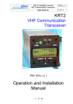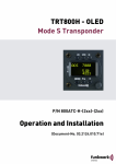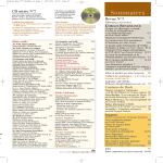
1
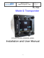
Operation Manual
Mode-S Transponder – KTX2
Doc.-Nr:
DE-3001-800100
Revision 2.7
KTX2
Mode-S Transponder
KTX-2-P/N 210-(XXXXX)-(XXX)
Installation and User Manual
-1-
Doc.-Nr:
Operation Manual
Mode-S Transponder – KTX2
DE-3001-800100
Revision 2.7
Revision List
Revision
Date
Topic
1.0
1.1
2.0
2.1
2.2
2.3 to 2.7
20 Oct 2014
28 Oct.2014
May 2015
Jun 2015
July 2015
Nov 2015
Initial Release
Added SW 2.07
New colour display
No extend. SQ.
Weight-on-wheels
Editorial corrections
Service Bulletins (SB)
The service Bulletin must be inserted in the manual and added to this table.
No
No SB
Release date
Date Added
Name
Rev.
Release
Activity
Name
Signature
Prepared by:
B. Korndörfer
Checked by:
Y. Rodenas
Approved by:
K. Attig
-2-
Date
21 Oct 2014
Operation Manual
Mode-S Transponder – KTX2
Doc.-Nr:
DE-3001-800100
Revision 2.7
Change history
Product
Revision
P5
Date
Description of Change
21 Oct 2014 Base Version
SW 2.07
28 Oct 2014 Updated with Software 2.07.
SW 2.08
18 Mar 2015 Updated with Software 2.08
Aug.2015
Interface description
Sept. 2015
Supplemental indications
-3-
Operation Manual
Mode-S Transponder – KTX2
Doc.-Nr:
DE-3001-800100
Revision 2.7
Table of Contents
1.
GENERAL ................................................................................... - 6 -
1.1.
1.2.
1.3.
1.4.
2.
Symbols ...................................................................................... - 6 Abbreviation................................................................................ - 7 Customer Support....................................................................... - 8 Features ..................................................................................... - 9 Operation ...................................................................................- 10 -
2.1. Controls .....................................................................................- 10 2.1.1. Keyes ...................................................................................- 11 2.1.2. Values ..................................................................................- 12 2.2. ON/OFF .....................................................................................- 13 2.3. Display brightness .....................................................................- 14 2.4. Transponder-Modes ..................................................................- 14 2.5. Squawk-Setting .........................................................................- 15 2.6. VFR – Squawk ...........................................................................- 15 2.7. Squawk Ident (ID, SPI) ..............................................................- 16 2.8. Flight/GND indication .................................................................- 16 2.9. Flight-ID (FID) & Set-Up.............................................................- 16 2.9.1. General ................................................................................- 16 2.9.2. Entering Set Up ....................................................................- 17 2.9.3. Set Flight-ID (FID) ................................................................- 18 2.10. Supplemental indications ...........................................................- 19 2.10.1. Set Up ..................................................................................- 20 2.9.4.1 Aircraft address (AA)............................................ - 20 2.9.4.2 Ground switch ...................................................... - 21 2.9.4.3 Speed category.................................................... - 21 2.9.4.4 Serial interface ..................................................... - 21 2.9.4.5 Multiple use ......................................................... - 22 2.10.2. Use of multiple aircraft .........................................................- 23 2.11. Operation with multiple registrations ..........................................- 23 3.
Self-Test (Errors) .......................................................................- 25 3.1. Setup Error ................................................................................- 25 3.2. External warnings/errors ............................................................- 26 3.2.1. General control ....................................................................- 26 3.3. Basic Errors ...............................................................................- 27 4.
Installation ..................................................................................- 28 4.1. Equipment Connections .............................................................- 28 4.1.1. Electrical Connections ..........................................................- 28 4.1.2. Mutual Suppression .............................................................- 28 4.1.3. Ground Switch .....................................................................- 28 4.1.4. Interface ...............................................................................- 29 -4-
Operation Manual
Mode-S Transponder – KTX2
Doc.-Nr:
DE-3001-800100
Revision 2.7
4.1.5. Static Air Port .......................................................................- 29 4.2. Wiring ........................................................................................- 30 4.2.1. Conductor Cross Section .....................................................- 30 5.
Drawings ....................................................................................- 31 5.1. KTX-2 ........................................................................................- 31 6.
Technical Data ...........................................................................- 32 6.1. General......................................................................................- 32 6.1. Transmitter - Receiver ...............................................................- 33 -
-5-
Operation Manual
Mode-S Transponder – KTX2
Doc.-Nr:
DE-3001-800100
Revision 2.7
1. GENERAL
This manual contains information about the physical, mechanical and
electrical characteristics, installation and operation of the Mode S
Transponder KTX-2.
1.1. Symbols
DANGER:
Advices whose non-observance can cause radiation
damage to the human body or ignition of combustible
materials.
Attention:
Advices whose non-observance can cause damage to the
device or other parts of the equipment. or can reduce the
correct functionality of the device.
INFORMATION
-6-
Doc.-Nr:
Operation Manual
Mode-S Transponder – KTX2
DE-3001-800100
Revision 2.7
1.2. Abbreviation
Abb.
Meaning
Explanation
FID
Flight ID
Flight plan number or if not assigned
registration number of aircraft
SPI
Special Position
Identification
Activation on request by controllers
„Squawk Ident“, transmits SPI Pulse for 18
seconds, which highlights the respective
traffic item on the controllers radar screen
AA
Aircraft Address
Assigned ICAO 24 bit address
AC
Aircraft Category
Defines aircraft type into specific
categories
RI
Reply Information
Classified airspeed
-7-
Operation Manual
Mode-S Transponder – KTX2
Doc.-Nr:
DE-3001-800100
Revision 2.7
1.3. Customer Support
In order to facilitate a rapid handling, please fill in the form for complains
and shop returns available on the AIRplus Avionics web site.
www.AIRplus24.com.
Any suggestions for improvement of our manuals are
welcome. Contact: [email protected].
Information on software updates are available at AIRplus.
www.airplus24.com
-8-
Operation Manual
Mode-S Transponder – KTX2
Doc.-Nr:
DE-3001-800100
Revision 2.7
1.4. Features
In order to operate the Mode-S transponder it is necessary
to request (in time) an ICAO 24-Bit Aircraft Address at the
responsible national aviation authorities. The received
code must be configured within the transponder (see
chapter 2.9. Flight-ID & Set-UP)
• Class 1 Level 2 transponders are of Non-Diversity Mode-S type
for ground based interrogations on 1030 MHz and respond
on1090 MHz
• Replies to (Secondary) Radar Interrogations
Mode-A replies with a Squawk (one of 4096 possible
Codes; e.g. flight plan number, Squawk assigned by a
Controller or the VFR Squawk 7000)
Mode C replies, including encoded flight level
Mode S replies, including aircraft address and flight level
• IDENT capability for activating the Special Position
Identification“- Pulse (SPI) for 18 seconds, on the Air Traffic
Controller´s request to „Squawk Ident“
• Maximum flight level 35 000ft; maximum airspeed 250kt
• Display information contains Squawk code, mode of operation
and pressure altitude.
• Temperature compensated high precision piezo-resistive
pressure sensor
• RS-232 data port enabling connection with certain GPSReceivers in order to support ADS-B Out
• 8 storable entries for AA-/AC-Code, FID, Ground-Switch, RI-Code
and GPS-/Interface-setting
• Depending on certification there is a RS-232 data port
enabling connection with certain GPS-Receivers to support
ADS-B Out
-9-
Operation Manual
Mode-S Transponder – KTX2
2. Operation
2.1. Controls
- 10 -
Doc.-Nr:
DE-3001-800100
Revision 2.7
Operation Manual
Mode-S Transponder – KTX2
2.1.1.
Key
Doc.-Nr:
DE-3001-800100
Revision 2.7
Keyes
Meaning
Remarks
ON/OFF
This switch is mechanically locked ON until pushed a
second time.
1. activates VFR Squawk
(press shortly)
VFR
2. stores the standby squawk as VFR/VFRW-Squawk
(press button 3 s) see chapter 2.6
1. exchanges the Active and Standby-Squawk
CHANGE
2. works as cursor back button when entering values
and also for navigating backwards within the
configuration menu (see chapter 2.5)
IDENT
„Squawk Ident“, sends Ident marking (SPI) for
18 s when in the normal mode
see chapter. 2.9
MDE
Selects Transponder- Modes STBY, ON, GND, ALT
see chapter 2.4
Rotary knob
Enters values at current cursor position, selects options
and sets the Standby Squawk
Sets the cursor position
& CURSOR
- 11 -
Operation Manual
Mode-S Transponder – KTX2
2.1.2.
Value
Doc.-Nr:
DE-3001-800100
Revision 2.7
Values
Meaning
Remarks
Transponder is transmitting:
Replies on Interrogations
• Appears per reply
• appears at every
addressed reply
1224
Transponder is locked by a
ground station and will be
directly addressed
active Squawk
BAT
Battery power too low
blinking
ID
transmits IDENT- Marking
ID („Squawk Ident“) has been
pressed – active for 18 s
FL010
Flight Level
Flight Level (in 100 ft steps)
ALT
Mode display
(STBY, ON, GND, ALT)
Modes
see chapter. “2.4TransponderModes”
4344
Standby-Squawk
Can be exchanged with active
squawk by pushing the UP/DOWN
button
- 12 -
Operation Manual
Mode-S Transponder – KTX2
Doc.-Nr:
DE-3001-800100
Revision 2.7
2.2. ON/OFF
The device is switched ON/OFF by pushing the mechanically locked
switch.
When the transponder is ON, the initial page is as follows (Example):
Device Name
KTX2 (KTX2-B)
Software-Version
e.g. V3.00
Firmware-Version
e.g. FPGA: 4.8
(displays 2 sec later)
After app. 4 seconds the normal operation window appears and the
transponder will enter the mode ALT. If an automatic ground detection is
installed and the aircraft is on ground the mode GND will be set.
No GND switch installed
GND-switch installed, on GND
- 13 -
Operation Manual
Mode-S Transponder – KTX2
Doc.-Nr:
DE-3001-800100
Revision 2.7
2.3. Display brightness
Push the MDE button until STBY is indicated then
Push the ID button for 2 sec.
In the upper right corner the display shows DIM x. Change the setting
with the rotary knob. Return to normal operation is automatic.
2.4. Transponder-Modes
The active mode is displayed in the lower left corner.
SBY
GND
ON
ALT
Transponder is on but does not respond to any interrogation.
Transponder responds to Mode-S interrogations.
Transponder responds to all interrogations, only altitude is not
transmitted.
Transponder responds to all interrogations
During the flight the Mode ALT should always be set, unless the
controller requests another mode.
While on ground, the transponder should be set to GND, unless an
AIR/GND-switch (Squat switch) is installed. In this case, the mode
changes automatically.
Mode-selection is done by repeatedly pushing the MDE button
- 14 -
Operation Manual
Mode-S Transponder – KTX2
Doc.-Nr:
DE-3001-800100
Revision 2.7
2.5. Squawk-Setting
The active Squawk is displayed on top, the Standby- Squawk is
shown and changed below.
Setting of the Standby-Squawks:
• Setting the Squawk is done by rotating and pushing the rotary
knob. Pushing the rotary knob repeatedly highlights the
character to be changed.
• The UP/DOWN button exchanges the Active and the
Standby Squawk when in the normal mode. The left arrow
indicates navigating backwards when in any menu.
2.6. VFR – Squawk
The factory setting of the VFR transponder code is 7000. The VFR
transponder code however can be user defined.
• To activate the VFR-Squawk push the VFR button. VFR is then
indicated on the display.
- 15 -
Operation Manual
Mode-S Transponder – KTX2
Doc.-Nr:
DE-3001-800100
Revision 2.7
• When "VFR" is NOT displayed a user defined VFR transponder
code can be selected in the standby window by pushing and
turning the rotary knob.
• In order to store this new transponder code, wait until no
individual character in the standby window is highlighted, then
push and hold the VFR button until "S" is indicated on the display
after approximately 3 seconds.
2.7. Squawk Ident (ID, SPI)
On request of the radar controller push the ID button when not in the
STBY mode. Transmission of the ID signal will last for 18 seconds and is
displayed above the mode.
2.8. Flight/GND indication
Aircrafts with AIR/GROUND switches display “F” (Flight) or “G” (Ground)
in the lower right corner.
This function must be activated in the set up procedure.
When this function is not activated, there are no indications on the display
and modes must be manually selected.
2.9. Flight-ID (FID) & Set-Up
2.9.1. General
ICAO regulations require Mode-S data to contain a valid flight
identification (FID), to ensure automatic exchange of flight plan and radar
data.
There are 3 types of FIDs
Aircraft identification as specified in item 7 of the ICAO flight plan.
Company flight plan e.g. KLM511, BAW213, LH400
Aircraft registration e.g. DEABC, FPQUM
FID entries must be left aligned and may not contain any dashes, spaces,
blanks or zeros. Not used remaining right digits must be blank.
- 16 -
Operation Manual
Mode-S Transponder – KTX2
2.9.2.
Doc.-Nr:
DE-3001-800100
Revision 2.7
Entering Set Up
Flight-ID or Set-Up changes can only be done when in the STBY
mode.
Push the MDE button repeatedly until „STBY“ appears
Push and hold the ID button.
“DIM x”
(for dimming)
appears from 0 to 5 seconds
“setFID“
(for setting of flight ID)
appears from 5 to 8 seconds
“SetUP”
(for the Set up menu)
appears after 8 seconds
Just release the ID button when the appropriate menu is displayed.
The setFID-Menus will be active for 10 seconds. When there is no input
within 10 seconds the respective menu is left automatically.
The setUP-Menu is not for normal operation and it will remain active until
normal termination.
KTX-2 setUP menu initial display
The ID and MDE buttons are used as softkeys in these menus. Their
function is displayed by symbols or text next to the respective buttons.
“skip“ or “OK” means advance to the next menu item.
“->“ (= next) means move cursor one position to the right.
- 17 -
Operation Manual
Mode-S Transponder – KTX2
2.9.3.
Doc.-Nr:
DE-3001-800100
Revision 2.7
Set Flight-ID (FID)
The FID is required for Mode-S Operation. Commercial flights usually
have their own FIDs. General aviation FIDs should be the registration
letters or numbers of the aircraft. The FID must not be confused with the
24-bit Aircraft Address. The green part is the 24 bit address (AA) and the
red part is the aircraft category (AC). The FID is left aligned and shown in
white characters. The FID may not contain blanks however the non used
most right characters must be blank. The FID must start with the
nationality code. If the first left sign is a blank the whole AA-setup will be
deactivated.
Skip the button next “skip” will leave the menu without any changes.
Only the FID can be changed in this menu.
“^” marks the cursor position.
Pushing the ID button (skip) cancels the input.
Pushing the MDE button (OK) saves the FID and the menu will be
terminated automatically after 10 seconds.
Enter FID left-aligned, without any blanks or dashes (!), e.g.
3FEBA11CDMDBO for the marking D-MDBO. The last
remaining digits must be blank.
FID containing blanks characters are invalid.
Missing FID disables mode-S operation and A/C-mode only
will be engaged.
See chapter Self-Test
- 18 -
Operation Manual
Mode-S Transponder – KTX2
Doc.-Nr:
DE-3001-800100
Revision 2.7
2.10. Supplemental indications
Using the reply some additional usefull indications are provided:
Small arrow indicates mode-A/C reply
Wide arrow indicates mode-S reply
A dot at the left side is for an addressed interrogation which
indicates that the transponder is known in the radar system.
An additional dot at the right side indicates the reception of
correct GPS-position data.
- 19 -
Operation Manual
Mode-S Transponder – KTX2
Doc.-Nr:
DE-3001-800100
Revision 2.7
2.10.1. Set Up
2.9.4.1 Aircraft address (AA)
When in the STBY mode push and hold the ID button until “setup“
appears.
This screen is the start menu for all further settings. On this page only the
6 green and 8 white characters of the Aircraft Address (AA) can be
changed.
Pushing the MDE button will save the present settings.
In the next screen the airplane category can be set, after a short time the
submenu comes up in sequence:
->
With the rotary knob one of 8 different vehicles classes can be selected.
•
•
•
•
•
•
•
•
FixW<5.7t
FixW>5.7t
GlidrSail
GasFilled
ParaShutr
ULM/HgPar
UAV
RotorCrft
=
=
=
=
=
=
=
=
Airplane until 5.7t
Airplane over 5.7t.
(not selectable)
Glider
Balloons
Parachutes
Ultra-light, Paraglider
Unmanned air vehicles
Helicopters
(not selectable)
Because the KRT2 is not certified for aircrafts > 5.7t and not for
helicopters (RotorCrft) these items are not selectable.
- 20 -
Operation Manual
Mode-S Transponder – KTX2
Doc.-Nr:
DE-3001-800100
Revision 2.7
Helicopters in micro light class and gyrocopters should use ULM/HgPar.
To save the selected Aircraft Category push the MDE button.
2.9.4.2 Ground switch
Then the next submenu is asking for the AIR/GND switch function.
YES/NO can be selected with the rotary knob.
To save the AIR/GDN function push the MDE button.
2.9.4.3 Speed category
Then the next submenu is asking for the typical cruising speed.
The typical cruising speed can be selected with the rotary knob.
To save the typical cruising speed, push the MDE button.
2.9.4.4 Serial interface
The last menu is for definition of the serial interface:
- 21 -
Operation Manual
Mode-S Transponder – KTX2
Doc.-Nr:
DE-3001-800100
Revision 2.7
At this point, the interface set up for different application can be defined.
The various applications can be remote control, automatic performance
tests or position data for ADS-B-out.
Details are described in a separate interface description, depending on
certification level .
Select with the rotary knob:
• INT: NON = (no connection)
Data speed available:
• INT: 4800 bd
• INT: 9600 bd
Save data by pushing the MDE button.
2.9.4.5 Multiple use
The next menu requires a decision to be made, whether to continue the
Set-Up procedure, or to terminate the Set-Up.
For a single permanently installed application the Set-Up procedure is
complete and will be terminated after pushing the MDE button (EXIT)..
-------------- End of normal Set Up ------------When the transponder is to be used on different vehicles, push the MDE
button (YES) and continue with the next chapter 2.9.5. Use of multiple
aircraft.
- 22 -
Operation Manual
Mode-S Transponder – KTX2
Doc.-Nr:
DE-3001-800100
Revision 2.7
2.10.2. Use of multiple aircraft
In case the transponder is to be used for more than one aircraft (e.g.
balloons) it is possible to enter up to 8 call signs. In this case every time
the transponder is switched on the respective call sign must be selected.
When this page is displayed, continue to input other aircraft data by
pushing the ID button (YES).
The next submenu is displayed.
Select a free position with the rotary knob and enter the next call sign.
Push the MDE button. Then the procedure as described in chapter 0 has
to be applied for every call sign in the list.
The right page above shows a list of two different call signs, respectively
aircraft, on which the transponder can be used.
Up to 8 call signs can be stored.
Delete an entry:
To delete an entry it is sufficient to delete the first letter of the call sign. It
is however recommended to delete the whole call sign.
2.11. Operation with multiple registrations
If there is more than 1 call sign stored, a list of up to 8 possible call sign
will appear when the transponder is switched on.
Select the appropriate call sign with the rotary knob and confirm with the
- 23 -
Operation Manual
Mode-S Transponder – KTX2
MDE button.
After 3 seconds the KTX2 resumes normal operation.
- 24 -
Doc.-Nr:
DE-3001-800100
Revision 2.7
Operation Manual
Mode-S Transponder – KTX2
Doc.-Nr:
DE-3001-800100
Revision 2.7
3. Self-Test (Errors)
The KTX2 distinguishes three different irregularities:
• Warning
• Setup-error
• Elementary function-error.
3.1. Setup Error
If no FID-Code (Flight Identification) is entered or the first character of the
8 character FID is blank, the following displays will appear after switching
on the transponder.
in this case transponder operation is limited to the A/C mode.
Available modes:
•
•
•
A/C = normal operation,
A-= no height feedback
STBY = operation on ground
- 25 -
Operation Manual
Mode-S Transponder – KTX2
3.2.
Doc.-Nr:
DE-3001-800100
Revision 2.7
External warnings/errors
When BAT is blinking the power supply voltage is less than 11V.
3.2.1.
General control
The antenna adjustment as well as the transmission power are surveyed,
the results are displayed above the flight level display (blinking).
Meaning of the following displays
• ANT : bad antenna adaption
• ANTx : antenna failed
• TRX : weak transmission
• TRXx : Transmitter probably failed
• DC_: Low Power voltage
• FPG: Internal transfer
- 26 -
Operation Manual
Mode-S Transponder – KTX2
3.3.
Doc.-Nr:
DE-3001-800100
Revision 2.7
Basic Errors
This kind of error is only produced by a severe malfunction of the device.
It also can be caused by power interruptions during start up of the
transponder.
If the message cannot be removed by switching the transponder on and
off repeatedly, it must be serviced.
System error, after unsuccessful restart –Service
ERROR stop
Er_FPGA
ERROR stop
Er_ADC
MEMORY
ERROR
System error, after unsuccessful restart –Service
System error, after unsuccessful restart –Service
System error, after unsuccessful restart –Service
in this case the KTX2 tries to go on in the A/C-mode.
- 27 -
Operation Manual
Mode-S Transponder – KTX2
Doc.-Nr:
DE-3001-800100
Revision 2.7
4. Installation
4.1.
4.1.1.
Equipment Connections
Electrical Connections
One 15 pin D-SUB miniature connector includes all electrical
connections, except for the antenna.
The (+UB)-wire has to be protected by a 2 Amp circuit breaker !
4.1.2.
Mutual Suppression
Other equipment on board (e. g. DME) may transmit on the same
frequency band as the transponder.
If such a device is installed a single wire bus (active at +12V) shall be
installed in order to protect the receiving parts of the different devices
from in-band transmissions.
Mutual suppression is a pulse that is sent to the other equipment to
suppress transmission of a competing transmitter for the duration of the
pulse train transmission. The transponder transmission may be
suppressed by an external source and vice versa.
To activate mutual suppression the SUPP_I/O requires a +12V from the
of the other equipment
4.1.3.
Ground Switch
If a Ground-Switch is connected (and activated in the Setup), the
transponder is enabled to distinguish between weight-on-wheel (OnGround) and In-Flight Condition. In weight-on-wheel condition the
transponder automatically enters the Standby mode.
In order to complete this installation the input „FLY-GND“ must be
connected to a switch which shorts the input to „GND“ in case there is
weight on wheels, or remains open during flight.
This option must additionally be activated in the Setup. For details on
configuration please refer to section Set Up.
- 28 -
Operation Manual
Mode-S Transponder – KTX2
Doc.-Nr:
DE-3001-800100
Revision 2.7
4.1.4.
Interface
A serial interface (RS232) is provided for GPS-Position data (ADS-B or /
and remote control), see 2.9.4.4.
As data format for GPS the standard NMEA-stream containing the RMCsub-format is required.
For remote control additional sub-formats like the RMC should be
inserted into the NMEA data stream. This format is presently not
implemented and it needs to be defined.
4.1.5.
Static Air Port
Install a silicon soft tube fitting on the 5 mm port of static air at the
backside of the transponder and secure plumbing with appropriate
clamps.
- 29 -
Operation Manual
Mode-S Transponder – KTX2
Doc.-Nr:
DE-3001-800100
Revision 2.7
4.2. Wiring
4.2.1.
Conductor Cross Section
Power Supply (Power, GND): AWG20 (0,62 mm²) Signals:
AWG22 (0,38 mm²) The conductors must be approved for aircraft use.
- 30 -
Operation Manual
Mode-S Transponder – KTX2
5. Drawings
5.1. KTX-2
Round Unit dimensions.
- 31 -
Doc.-Nr:
DE-3001-800100
Revision 2.7
Operation Manual
Mode-S Transponder – KTX2
Doc.-Nr:
DE-3001-800100
Revision 2.7
6. Technical Data
6.1. General
GENERAL
Authorization
ED-73E Level 2els,Class 1
ETSO-C112D
RTCA DO-178B/ED-12B Level D
RTCA DO-160F/ED-14F
Applied Standards
EUROCAE ED-26
EUROCAE ED-14F
EUROCAE ED-12C
Dimensions KTX-2
See drawings
Weight
Mounting
KTX-2= 0.37 kg ,
KTX-2: cut-out Ø 57 mm, KTX-2A ARING
Temperature ranges
Operation
-20 °C to +55 °C
Storage
-55 °C to +85 °C
MAX. flight level
35000 ft
Vibration
DO-160E, Cat. S, Vibration Curve M
Humidity
RTCA DO-160E, Cat. A
Shock
RTCA DO-160F ENV. CAT.
6G
20 G
operation
crash safety
[C1Z]CAA[SM]XXXXXXZBAAA[YY]M[B3F3]XXA
9 VDC to 33VDC test @ 12VDC
Power
Fuse
compass security distance
depending on the no. of requests 0.2 to 1.0A
Ilumination 0.02A
emergency operation: 9 VDC
external fuse required: 2 A, slow-blow
30 cm
- 32 -
Operation Manual
Mode-S Transponder – KTX2
6.1.
Doc.-Nr:
DE-3001-800100
Revision 2.7
Transmitter - Receiver
Transmitter
Receiver
Characteristics:
Sensitivity
RF input power level resulting in a 90 % reply
rate:
• MTL for ATCRBS and ATCRBS/Mode
S All-Call interrogations: -74 dBm
±3dB.
• MTL for Mode S interrogations: -74dBm
± 3 dB.
Reply
transmission
frequency
1090 ± 1 MHz
RF Peak Power
Output
≥ 21dBW (126 W) at antenna base (with
maximum cable attenuation of 1,5dB)
Squitter (ADS-B)
transmitted at random intervals
uniformly distributed over the range
from 0.8 to 1.2 seconds, full selfverification of data and occurrence
RECEIVER
ICAO 24-bit Aircraft
Address (Hex-Code)
aircraft address as assigned by national
aviation authority
FID
Capability Report
Flight ID: Flight Plan call sign or aircraft
registration marking
Pressure Altitude
Up to 35 000ft in 25ft increments inflight / on-ground
Flight Status
Reports the available data and means
by which the transponder can report.
- 33 -
Operation Manual
Mode-S Transponder – KTX2
AIRplus Maintenance GmbH
E-mail:
[email protected]
www.AIRplus-avionics.com
- 34 -
Doc.-Nr:
DE-3001-800100
Revision 2.7