1
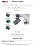
C0203 Intelligent Controller User Manual
7850 East Gelding Drive • Scottsdale, AZ 85260-3420
C0203 Intelligent Controller User Manual
Revision B
C0203
Intelligent Controller Version 1.1
NKK SWITCHES
7850 E. Gelding Drive
Scottsdale, AZ 85260
Toll Free 1-877-2BUYNKK (877-228-9655)
Phone 480-991-0942
Fax 480-998-1435
e-mail <[email protected]>
All Rights Reserved Worldwide
NKK Switches makes no warranty for the use of these products and assumes no responsibility for any errors,
which may appear in this document, nor does it make a commitment to update the information contained herein.
Smart Switch is trademark of NKK Switches.
C0203 User Manual.doc
Toll Free 1.877.2BUYNKK (877.228.9655) • Phone 480.991.0942 • Fax 480.998.1435
www.nkkswitches.com • Email [email protected]
Page 1 of 23
0409
C0203 Intelligent Controller User Manual
7850 East Gelding Drive • Scottsdale, AZ 85260-3420
TABLE OF CONTENTS
Table of Contents ..........................................................................................................2
1. General Controller Features ...................................................................................3
2. Compatible Logic Boards.........................................................................................3
3. Operational Overview..............................................................................................4
4. Operational Details ...................................................................................................7
5. Communication Protocol .........................................................................................9
6. Hardware ...................................................................................................................18
7. Key Terms & Definitions..........................................................................................23
8. Firmware problems ..................................................................................................23
C0203 User Manual.doc
Toll Free 1.877.2BUYNKK (877.228.9655) • Phone 480.991.0942 • Fax 480.998.1435
www.nkkswitches.com • Email [email protected]
Page 2 of 23
0409
C0203 Intelligent Controller User Manual
7850 East Gelding Drive • Scottsdale, AZ 85260-3420
1. General Controller Features
The C0203 controls two high resolution (64x32) switches/ displays or two standard (36x24) switches/ displays.
The firmware can be customized based on customer requirements. Below are current features:
•
•
•
•
•
•
•
•
•
•
Controls two high resolution (64x32) switches/ displays or two standard (36x24) switches/ displays
Serial communication via RS232 (57.6K, 1 start bit, 8 bit , 1 stop bit)
Optional audio feedback while switch is pressed.
Program responses to switch-actions events and timer-expire events.
User programmable for images, attributes and set-ups.
Set the type of activity reports from the controller to host.
LED Brightness settings.
Flash memory for 255 pictures and attributes.
Reports switch activity and timer expiration via serial port.
Stand alone operation or real time control by host.
2. Compatible Logic Boards
The following is a list of compatible Logic Boards and switches.
A. IS-L02A1-C
64x32 RGB
B. IS-L02F1-C
64x32 RGB Display
C. IS-L02H2-C
64x32 Compact
D. IS-L0204-C
E. IS-L0251-C
F. IS-L0271-C
Standard RGB
Standard RGB Display
Standard RGB Compact
G. IS-L0205-C
Standard Bicolor/single color
C0203 User Manual.doc
Toll Free 1.877.2BUYNKK (877.228.9655) • Phone 480.991.0942 • Fax 480.998.1435
www.nkkswitches.com • Email [email protected]
Page 3 of 23
0409
C0203 Intelligent Controller User Manual
7850 East Gelding Drive • Scottsdale, AZ 85260-3420
3. Operational Overview
Power-up Sequence:
Upon power up, the controller checks the position of the Mode Select Switch. The switch position has to match
the logic board/switches connected. The “High res” position will work only for High Resolution (64x32)
switches/ displays while the “Standard res” position will work only for Standard Resolution (36x24) switches/
displays.
Note: Setting the switch to a different setting than the Logic Board type may damage the assembly.
LED Brightness Adjustment Mode:
The controller will then allow the backlight brightness to be adjusted. Press the left hand switch to make both
LED modules dimmer. Press the right hand switch to make both LED modules brighter.
Main Operational Mode:
After a few seconds of user inactivity the controller will move into the main operations mode where the switch
on the left displays the image at the user’s first preset address. The right hand switch will display the image at
the user’s second preset address. The controller will then respond to a switch actuation or a timer expiration as
set by the user preset attributes.
Addresses:
A one byte value ranging from 01H to FFH representing the 255 memory.
Attribute Block for 64x32 Resolution Switches
A block of 8 bytes.
Byte
Description
1
Address for LCD Module #1
when switch is pressed.
2
Address for LCD Module #2
when switch is pressed
3
Address for LCD Module #1
when the timer is expired.
4
Address for LCD Module #2
when the timer is expired.
5
Value for TIMER 1
6
Value for TIMER 2
7
LED CODE for on cycle
8
LED CODE for off cycle
C0203 User Manual.doc
Toll Free 1.877.2BUYNKK (877.228.9655) • Phone 480.991.0942 • Fax 480.998.1435
www.nkkswitches.com • Email [email protected]
Page 4 of 23
0409
C0203 Intelligent Controller User Manual
7850 East Gelding Drive • Scottsdale, AZ 85260-3420
LED Backlighting for 64x32 Resolution Switches:
The LED code has two bytes, one byte for “on cycle” and one byte for “off cycle”. The format for both bytes is
the same. Following is the byte format:
B7
R
B6
R
B5
G
B4
G
B3
B
B2
B
B1
1
B0
1
For each of red, green and blue color:
00=off
01= ¼ brightness
10 = ½ brightness
11= full brightness
Image Block for 64x32 Resolution Switches:
Bit map format for the Legend block
Byte 8
Byte 7
…
Byte2
D7D6D5D4D3D2D1D0
D7D6…D1D0
…
D7D6…D1D0
Byte 16
…
D7D6D5D4D3D2D1D0
…
.
.
…
.
.
.
…
.
.
.
…
.
.
.
…
.
Byte 256
…
D7D6D5D4D3D2D1D0
D7D6…D1D0
…
D7D6…D1D0
Please note this bit map is different than the switch bitmap.
Byte 1
D7D6D5D4D3D2D1D0
Byte 9
D7D6D5D4D3D2D1D0
.
.
.
.
Byte 249
D7D6D5D4D3D2D1D0
Attribute Block for 36x24 Resolution Switches
A block of 6 bytes.
Byte
Description
1
Address for LCD Module #1 when switch is pressed.
2
Address for LCD Module #2 when switch is pressed
3
Address for LCD Module #1 when the timer is expired.
4
Address for LCD Module #2 when the timer is expired.
5
Value for TIMER 1
6
Value for TIMER 2
C0203 User Manual.doc
Toll Free 1.877.2BUYNKK (877.228.9655) • Phone 480.991.0942 • Fax 480.998.1435
www.nkkswitches.com • Email [email protected]
Page 5 of 23
0409
C0203 Intelligent Controller User Manual
7850 East Gelding Drive • Scottsdale, AZ 85260-3420
Image Block for 36x24 Resolution Switches:
A block of 125 bytes. It contains picture data and LED codes.
Byte
Description
1-5
First line of picture
6-10
Second line of picture
•
•
•
116-120
24th line of picture
121
LED code
122-125
reserved
LED Backlighting for 36x24 Resolution Switches:
The LED code is one byte with the following format:
B7=0 ==> Reserved
B7=1 ==> Reserved
B6=0 ==> Blue backlighting off during "OFF CYCLE"
B6=1 ==> Blue backlighting on during "OFF CYCLE"
B5=0 ==> Green backlighting off during "OFF CYCLE"
B5=1 ==> Green backlighting on during "OFF CYCLE"
B4=0 ==> Red backlighting off during "OFF CYCLE"
B4=1 ==> Red backlighting on during "OFF CYCLE"
B3=0 ==> LCD normal
B3=1 ==> LCD inverse
B2=0 ==> Blue backlighting off during "ON CYCLE"
B2=1 ==> Blue backlighting on during "ON CYCLE"
B1=0 ==> Green backlighting off during "ON CYCLE"
B1=1 ==> Green backlighting on during "ON CYCLE"
B0=0 ==> RED backlighting off during "ON CYCLE"
B0=1 ==> RED backlighting on during "ON CYCLE"
C0203 User Manual.doc
Toll Free 1.877.2BUYNKK (877.228.9655) • Phone 480.991.0942 • Fax 480.998.1435
www.nkkswitches.com • Email [email protected]
Page 6 of 23
0409
C0203 Intelligent Controller User Manual
7850 East Gelding Drive • Scottsdale, AZ 85260-3420
4. Operational Details
Power-Up Sequence (Steps 1,2,3)
Upon power-up or reset, controller performs the following steps:
Step 1: Check the status of Mode Select Switch for mode of operation. Initialize according to selected mode.
Step 2: Check if the flash RAM has been programmed. Compare the check string to flash RAM string.
A. If the strings are not the same, the flash RAM is virgin and its data is not acceptable. Step 3 will be
executed. (first time)
B. If the strings are the same, the data from RAM is acceptable. Step 3 is omitted and Step 4 is
executed.
Step 3: Write all the default initialize values to the flash memory as follows:
A. Put “BLANK FONT MEMORY” as the picture for location one.
B. Put “BLANK FONT MEMORY” as the picture for location two.
C. Put ONcycle LED’s ON for location #1 and #2.
D. Put OFFcycle LED’s off for location #1 and #2.
E. Put “00H 00H 00H 00H 00H 00H” as attribute for location #1 and #2.
F. Put 00H for software version
G. Write the default setup values such OFFcycle, ON/OFF ratio…
H. Write the virgin check string.
Step 4: LED brightness adjustment as follows:
A. Display “DOWN LED” and “UP LED” on the two switches and allow for adjustments of the
brightness. There are 8 brightness levels (0 to 7). When the internal timer is expired, the controller
proceeds to Step 5. Every time a switch is pressed, the timer gets reset. If a switch is held
depressed the timer does not run. Switch activity are not reported to host.
B. When the timer expires transmit 83H
C. Initialize and load the data from location 1 and 2 of EEPROM to internal RAM for switch 1 and 2
respectfully.
Main Operational Mode
Step 5:
A. If the switch one is pressed: Transmit 81H to host and execute the attribute.
(For details see Attribute Execution)
B. If the switch two is pressed: Transmit 82H to host and execute the attribute.
(For details see Attribute Execution)
C. If the timer for switch 1 is expired: Transmit 83H to host and execute the timer attribute.
(For details see Attribute Execution)
D. If the timer for switch 2 is expired: Transmit 84H to host and execute the timer attribute.
(For details see Attribute Execution)
E. If the switch one is released: Transmit B1H to host.
F. If the switch two is released: Transmit B2H to host.
C0203 User Manual.doc
Toll Free 1.877.2BUYNKK (877.228.9655) • Phone 480.991.0942 • Fax 480.998.1435
www.nkkswitches.com • Email [email protected]
Page 7 of 23
0409
C0203 Intelligent Controller User Manual
7850 East Gelding Drive • Scottsdale, AZ 85260-3420
G. Checks the host communication buffer for data. If there is data, process them.
(For details see Communication Protocol)
H. Go to step 5 section A
Attributes Execution
When a switch is pressed the attributes are executed as follows:
A. The timer for the switch is reset and does not run until the switch is released.
B. If byte 1 of the switch attributes is not equal to zero then the Legend block and attribute block from the
EEPROM is transferred to internal RAM for switch 1. The Legend, backlighting and timer values are
put in effect for switch 1.
C. If byte 1 of the switch attributes is equal zero then there will be no change to Legend/attribute of the
switch 1.
D. If byte 2 of the switch attributes is not equal to zero then the Legend block and attribute block from the
EEPROM is transferred to internal RAM for switch 2. The Legend, backlighting and timer values are
put in effect for switch 2.
E. If byte 2 of the switch attributes is equal zero then there will be no change to Legend/attribute of the
switch 2.
When one of the timers is expired the attributes are executed as follows:
A. The timer that expired gets reset.
B. Both timers will pause until attributes are executed.
C. If byte 3 of switch attributes is not equal zero then the Legend block and attribute block from the
EEPROM is transferred to internal RAM for switch 1. The Legend, backlighting and timer values are
put in effect for switch 1.
D. If byte 3 of switch attributes is equal zero then there will be no change to Legend/attributes of the switch
1.
E. If byte 4 of the switch attributes is not equal to zero then the Legend block and attribute block from the
EEPROM is transferred to internal RAM for switch 2. The Legend, backlighting and timer values are
put in effect for switch 2.
F. If byte 4 of the switch attributes is equal zero then there will be no change to Legend/attribute of the
switch 2.
Timers Operation
• Switch one and switch two timers run independently.
• Timer will be disabled if the timer 1 value is zero.
• The timer value in second = (TIMER 1)x(TIMER 2)x(0.0369)
• TIMER 2 = 0 count as 256.
C0203 User Manual.doc
Toll Free 1.877.2BUYNKK (877.228.9655) • Phone 480.991.0942 • Fax 480.998.1435
www.nkkswitches.com • Email [email protected]
Page 8 of 23
0409
C0203 Intelligent Controller User Manual
7850 East Gelding Drive • Scottsdale, AZ 85260-3420
5. Communication Protocol
The controller communicates with the host by serial communication via RS232 (57.6K, 1 start bit, 8 bit, 1
stop bit). The controller receives the data via an interrupt routine that places the data on the circular receive
buffer. When the controller detects data in the circular receive buffer, at Step 5G, it reads one byte and
executes the following:
A. If the byte is a command, the controller transmits a 61H and executes the subroutine for the command
and upon completion of command the controller transmits 79H. All of the commands are explained in
detail in this section.
B. If the byte is not a command, it is ignored.
When the controller executes a subroutine and expects additional information:
A. A timer is set. If the expected data byte is not received in 50ms, the controller transmits 6EH and
terminates the routine.
B. If the byte value is not acceptable (invalid range, option, etc.), the controller transmits 6EH and
terminates the routine.
Commands are one byte in the range of 20H to 2FH and 01H and are transmitted in hex format. The proper
format for all command options and data is specified for each command.
Commands to the controller
Command to reboot the controller
The command reboots the controller to power-up state.
command format:
transmit format:
24H
(xxH)
Command to check communication
The command is used to check if the controller is on-line.
command format:
transmit format:
01H
(xxH)
The controller transmits back 61H to the host.
Command to download a Legend block
This command downloads a Legend block from the host to the EEPROM location.
command format: 28H [Address] [Legend Block]
transmit format: (xxH) (xxAH)
(xxAH)
C0203 User Manual.doc
Toll Free 1.877.2BUYNKK (877.228.9655) • Phone 480.991.0942 • Fax 480.998.1435
www.nkkswitches.com • Email [email protected]
Page 9 of 23
0409
C0203 Intelligent Controller User Manual
7850 East Gelding Drive • Scottsdale, AZ 85260-3420
[Address] is one byte with value of 01H to FFH sent as ASCII HEX format.
[Legend Block] is 125 bytes in standard resolution mode and is 256 bytes in high resolution mode transmitted
in ASCII HEX format.
The controller disables the timers and switch execution upon receiving this command. However, the switches
are still scanned and reported. They are enabled upon reboot/power up or by command from host.
Command to upload a Legend block
This command uploads a Legend block from the EEPROM location to the host.
command format: 29H [Address]
transmit format: (xxH) (xxAH)
[Address] is one byte with value of 01H to FFH sent as ASCII HEX format.
The controller transmits back the image (125 bytes in standard resolution mode and is 256 bytes in high
resolution mode) in HEX format.
The controller disables the timers and switch execution upon receiving this command. However, the switches
are still scanned and reported. They are enabled upon reboot/power up or by command from host.
Command to download attribute block
This command downloads an attribute block from the host to the EEPROM location.
command format: 2AH [Address] [Attribute Block]
transmit format: (xxH) (xxAH)
(xxAH)
[Address] is one byte with value of 01H to FFH sent as ASCII HEX format.
[Attribute Block] is six bytes in standard resolution mode and is eight bytes in high resolution mode
transmitted in ASCII HEX format.
The controller disables the timers and switch execution upon receiving this command. However, the switches
are still scanned and reported. They are enabled upon reboot/power up or by command from host.
Command to upload an attribute block
This command uploads an attribute block from the EEPROM location to the host.
command format: 2BH [Address]
transmit format: (xxH) (xxAH)
[Address] is one byte with value of 01H to FFH sent as ASCII HEX format.
[Attribute Block] is six bytes in standard resolution mode and is eight bytes in high resolution mode
transmitted in ASCII HEX format.
The controller transmits back the [Attribute block] in hex format.
C0203 User Manual.doc
Toll Free 1.877.2BUYNKK (877.228.9655) • Phone 480.991.0942 • Fax 480.998.1435
www.nkkswitches.com • Email [email protected]
Page 10 of 23
0409
C0203 Intelligent Controller User Manual
7850 East Gelding Drive • Scottsdale, AZ 85260-3420
The controller disables the timers and switch execution upon receiving this command. However, the switches
are still scanned and reported. They are enabled upon reboot/power up or by command from host.
Command to set LED codes
This command sets the LED backlights according to the command’s LED codes.
command format: 2CH
00H [LED for Switch 1] [LED for Switch 2]
transmit format: (xxH) (xxAH)
(xxAH)
(xxAH)
[LED for switch 1] is one byte for standard resolution and two bytes for high resolution (first byte for on-cycle
and second byte for off cycle).
[LED for switch 2] is one byte for standard resolution and two bytes for high resolution (first byte for on-cycle
and second byte for off cycle).
Example: The following hex string makes switch 1 display green for “ON/OFF CYCLE” and switch 2
display white for ‘ON CYCLE’ and red for “OFF CYCLE”
For standard resolution mode
2C 00 3232 3137
For high resolution mode
2C 00 3333 3333 4646 4233
Command to transfer from EEPROM to internal RAM by Addresses
This command transfers the data from EEPROM to internal RAM according to the addresses. If either of
the address values is zero no transfer takes place for that address.
command format: 2DH 00H [Address for Switch 1] [Address for Switch 2]
transmit format: (xxH) (xxH)
(xxAH)
(xxAH)
[Address for Switch 1] is one byte with value of 00H to FFH.
[Address for Switch 2] is one byte with value of 00H to FFH.
Example: The following hex string makes switch 1 display the data from location 5 and makes switch 2
display the data from location 6. 2D 00 3035 3036
Command to transfer from EEPROM to internal RAM for one Address
This command updates the specified switch with the data from EEPROM using the address.
command format: 2EH [LCD Module #] [Address]
transmit format: (xxH) (31H or 32H)
(xxAH)
[LCD Module #] is the switch number (31H for switch 1, 32H for switch 2)
[Address] is one byte with value of 01H to FFH.
C0203 User Manual.doc
Toll Free 1.877.2BUYNKK (877.228.9655) • Phone 480.991.0942 • Fax 480.998.1435
www.nkkswitches.com • Email [email protected]
Page 11 of 23
0409
C0203 Intelligent Controller User Manual
7850 East Gelding Drive • Scottsdale, AZ 85260-3420
Command to set one LCD/LED Code
This command updates the LED’s of specified switch with the LED code.
command format: 2FH [LCD Module #] [LED code]
transmit format: (xxH) (31H or 32H)
(xxAH)
[LCD Module #] is the switch number (31H for switch 1, 32H for switch 2)
[LED code] is one byte for standard resolution and two bytes for high resolution (first byte for on-cycle and
second byte for off cycle). B0 and B1 must be 1 for high resolution.
Command to query controller for mode, controller, and firmware version
This command queries the controller for the mode as set by the Mode Select Switch, the controller
name, and the firmware version installed.
command format: 26H 52H 58H
transmit format: (xxH) (xxH) (xxH)
Example: The command is sent. The controller responds with the following:
61
61H
31
[mode]
43 30 32 30 33
[Controller name]
3131
[version]
79
79H
[mode] is one byte. 31H indicates standard resolution module mode or 32H indicates high resolution mode.
[Controller name] is five bytes. 43H 30H 32H 30H 33H (C0203)
[version] is one byte. 12H (version 1.1)
Command to upload the active Addresses
This command transmits 61H followed by the active addresses for switch 1 and 2 in hex format.
command format: 26H 00H
transmit format: (xxH) (xxH)
Command to set the data version
This command sets the version of the data in the FLASH memory. Default value (00H).
command format: 26H 42H [Data Version]
transmit format: (xxH) (xxH)
(xxAH)
Command to upload the data version
This command uploads the version of the data in the FLASH memory to the host in one byte HEX
format.
command format: 26H 41H
transmit format: (xxH) (xxH)
C0203 User Manual.doc
Toll Free 1.877.2BUYNKK (877.228.9655) • Phone 480.991.0942 • Fax 480.998.1435
www.nkkswitches.com • Email [email protected]
Page 12 of 23
0409
C0203 Intelligent Controller User Manual
7850 East Gelding Drive • Scottsdale, AZ 85260-3420
Command to uploads the FIRMWARE version
This command uploads the FIRMWARE version to the host in one byte HEX format.
command format: 26H 15H
transmit format: (xxH) (xxH)
Command to set LED Brightness
This command sets the LED brightness for the duration of the session.
command format: 26H 51H 53H [LED Brightness]
transmit format: (xxH) (xxH) (xxH)
(xxAH)
[LED BRIGHTNESS] is one byte from 00H (dimmest) to 07H (brightest). The upper 5 bits of the byte are
ignored.
This command is for duration of the session. It can become permanent by “Command to write the setup
values to the EPROM”.
Command to set LED press value
This command sets the LED code for when the switch is pressed. It applies to standard resolution
switches only.
command format: 26H 51H 55H [LED code]
transmit format: (xxH) (xxH) (xxH)
(xxAH)
[LED code] is one byte for standard resolution. B0 of FLAG A must be set. Standard resolution only
This command is for duration of the session. It can become permanent by “Command to write the setup
values to the EPROM”.
Command to set LED off cycle duration
This command sets the duration of the off cycle.
command format: 26H 51H 57H [LED OFF cycle]
transmit format: (xxH) (xxH) (xxH)
(xxAH)
[LED OFF cycle] is one byte.
This command is for duration of the session. It can become permanent by “Command to write the setup
values to the EPROM”.
C0203 User Manual.doc
Toll Free 1.877.2BUYNKK (877.228.9655) • Phone 480.991.0942 • Fax 480.998.1435
www.nkkswitches.com • Email [email protected]
Page 13 of 23
0409
C0203 Intelligent Controller User Manual
7850 East Gelding Drive • Scottsdale, AZ 85260-3420
Command to set LED on cycle duration
This command sets the duration of the on cycle.
command format: 26H 51H 59H [LED ON/OFF cycle]
transmit format: (xxH) (xxH) (xxH)
(xxAH)
[LED ON/OFF cycle] is one byte.
Duration of ON cycle = ([LED ON/OFF]-1) *(duration of OFF cycle)
This command is for duration of the session. It can become permanent by “Command to write the setup
values to the EPROM”.
Command to set FLAG A
This command sets Flag A.
command format: 26H 51H 5BH [FLAG A]
transmit format: (xxH) (xxH) (xxH) (xxAH)
[FLAG A] is one byte. See table below.
This command is for duration of the session. It can become permanent by “Command to write the setup
values to the EPROM”.
Flag Byte A Default Value=7EH
Bit Enable
Flag
Value
B0
1
LED press flag
B1
1
61H flag
B2
1
79H flag
B3
B4
1
1
Switch release report flag
6EH flag
B5
B6
B7
1
1
1
Switch press report flag
Timer 1 and 2 expire report flag
Address change report flag
Controller action when flag is set
Switch backlight change according to LED
press value while the switch is pressed.
For standard resolution only.
61H is transmitted in response to
command.
79H is transmitted upon completion of
command.
Switch releases are reported
6EH is transmitted if there is any error
during communication to host.
Switch presses are reported
Timer 1 and 2 expiration is reported
Newest address is reported for each switch
C0203 User Manual.doc
Toll Free 1.877.2BUYNKK (877.228.9655) • Phone 480.991.0942 • Fax 480.998.1435
www.nkkswitches.com • Email [email protected]
Page 14 of 23
0409
C0203 Intelligent Controller User Manual
7850 East Gelding Drive • Scottsdale, AZ 85260-3420
Command to download FLAG B
This command sets Flag B.
command format: 26H 51H 5CH [FLAG B]
transmit format: (xxH) (xxH) (xxH) (xxAH)
[FLAG B] is one byte. See table below.
This command is for duration of the session. It can become permanent by “Command to write the setup
values to the EPROM”.
Flag Byte B
Bit Enable
Value
B0
1
B1
0
B2
0
B3
0
B4
0
B5
0
B6
0
B7
0
Default Value=01H
Flag
BEEPER
Reserved
Reserved
Reserved
Reserved
Reserved
Reserved
Reserved
Controller action when flag is set
Beep for switch press
Command to set timers for LED up/ LED down
This command sets the timers that determine the time “DOWN LED” and “UP LED” are displayed upon
power up. Every time the switches are pressed the timers get reset.
command format: 26H 51H 5DH [Timer1] [Timer2]
transmit format: (xxH) (xxH) (xxH) (xxAH) (xxAH)
[Timer1] is one byte from 01H to FFH. 00H is not acceptable. Default (09H)
[Timer2] is one byte from 00H to FFH. 00H =256. Default (09H)
This command does not go to effect until it becomes permanent. It can become permanent by “Command to
write the setup values to the EPROM”.
Command to download power up Addresses
This command sets the addresses for switch 1 and switch 2 upon power up or reset.
command format: 26H 51H 5EH [Address for Switch 1] [Address for Switch 2]
transmit format: (xxH) (xxH) (xxH)
(xxAH)
(xxAH)
[Address for Switch 1] is one byte from 01H to FFH. 00H is not acceptable. Default (01H)
[Address for Switch 1] is one byte from 01H to FFH. 00H is not acceptable. Default (02H)
This command does not go to effect until it becomes permanent. It can become permanent by “Command to
write the setup values to the EPROM”.
C0203 User Manual.doc
Toll Free 1.877.2BUYNKK (877.228.9655) • Phone 480.991.0942 • Fax 480.998.1435
www.nkkswitches.com • Email [email protected]
Page 15 of 23
0409
C0203 Intelligent Controller User Manual
7850 East Gelding Drive • Scottsdale, AZ 85260-3420
Command to write the setup values to the EPROM
This command writes the setup values to the flash as per the following table. Once commanded the
values become permanent.
command format: 26H 51H 4FH 34H 46H
transmit format: (xxH) (xxH) (xxH) (xxH) (xxH)
• LED press value
• LED brightness level
• LED off cycle duration
• LED on/off cycle ratio
• FLAG A
• FLAG B
• Timers for LED up/LED down
• Power up addresses
Command to reset the setup values to the default values
This command writes the default values to the flash. Once commanded the values become permanent
after power up or reboot. Sets Addresses 01H and 02H memories to “BLANK FONT MEMORY”.
command format: 26H 51H 4EH 34H 45H
transmit format: (xxH) (xxH) (xxH) (xxH) (xxH)
Command to fill display with specified byte
This command displays a specified byte over all of the display.
command format: 27H [LCD Module #] 00H [Byte]
transmit format: (xxH) (31H or 32H) (xxH) (xxAH)
[LCD Module #] is the switch number (31H for switch 1, 32H for switch 2)
[Byte] Specified byte.
Command to transfer the RAM to specified address
This command transfers the RAM to the specified address.
command format: 27H [LCD Module #] 02H [Address]
transmit format: (xxH) (31H or 32H) (xxH) (xxAH)
[LCD Module #] is the switch number (31H for switch 1, 32H for switch 2)
[Address] is one byte with value of 01H to FFH.
C0203 User Manual.doc
Toll Free 1.877.2BUYNKK (877.228.9655) • Phone 480.991.0942 • Fax 480.998.1435
www.nkkswitches.com • Email [email protected]
Page 16 of 23
0409
C0203 Intelligent Controller User Manual
7850 East Gelding Drive • Scottsdale, AZ 85260-3420
Command to download ASCII string (7x10 fonts)
This command downloads and displays an ASCII string.
command format: 27H [LCD Module #] 70H [ASCII string]
transmit format: (xxH) (31H or 32H) (xxH)
(xxAH)
[LCD Module #] is the switch number (31H for switch 1, 32H for switch 2)
[ASCII string] is 8 characters for Standard and 24 characters for High resolution. The controller will make 2
lines of 4 characters using the 7x10 fonts for standard. The controller will make 3 lines of 8 characters using the
7x10 fonts for high resolution.
Standard: 8 ASCII characters. High resolution: 24 ASCII characters
Example: The following hex string makes switch 1 display A to X on high resolution.
27 31 70 4142 4344 4546 4748 494A 4B4C 4D4E 4F50 5152 5354 5556 5758
Command to download ASCII string (5x7 fonts)
This command downloads and displays an ASCII string.
command format: 27H [LCD Module #] 50H [ASCII string]
transmit format: (xxH) (31H or 32H) (xxH)
(xxAH)
[LCD Module #] is the switch number (31H for switch 1, 32H for switch 2)
[ASCII string] is 18 characters. The controller will make 3 lines of 8 characters using the 5x7 fonts for standard.
Standard: 18 ASCII characters. High resolution: not available.
Example: The following hex string makes switch 1 display A to X on standard resolution.
27 31 50 4142 4344 4546 4748 494A 4B4C 4D4E 4F50 5152
C0203 User Manual.doc
Toll Free 1.877.2BUYNKK (877.228.9655) • Phone 480.991.0942 • Fax 480.998.1435
www.nkkswitches.com • Email [email protected]
Page 17 of 23
0409
C0203 Intelligent Controller User Manual
7850 East Gelding Drive • Scottsdale, AZ 85260-3420
6. Hardware
Controls Overview
The Mode Select Switch has two settings; “High res” is for the High Resolution (64x32) switches/ displays and
“Standard res” is for the Standard RGB switches/ displays.
The Connector is for the installation of the Logic Boards onto the controller. One pin is keyed to reduce miss
mates.
Note: Improper installation of the Logic Boards could damage either/both the Logic Board and
controller.
The Batt/PWR switch has three positions: battery, off, line power.
Buzzer Volume adjusts the volume of the buzzer that activates when a button is pushed.
The 9V DC Power jack mates with a 2.5mm cylinder power connector. Center positive.
The RS232 Connector links the controller to the host.
1
RS232
2
GND
3
TX
4
RX
5
GND
6
C0203 User Manual.doc
Toll Free 1.877.2BUYNKK (877.228.9655) • Phone 480.991.0942 • Fax 480.998.1435
www.nkkswitches.com • Email [email protected]
Page 18 of 23
0409
C0203 Intelligent Controller User Manual
7850 East Gelding Drive • Scottsdale, AZ 85260-3420
Controller Schematic
Two Standard Resolution SmartSwitch, 36X24 RGB, logic board
C0203 User Manual.doc
Toll Free 1.877.2BUYNKK (877.228.9655) • Phone 480.991.0942 • Fax 480.998.1435
www.nkkswitches.com • Email [email protected]
Page 19 of 23
0409
C0203 Intelligent Controller User Manual
7850 East Gelding Drive • Scottsdale, AZ 85260-3420
C0203 User Manual.doc
Toll Free 1.877.2BUYNKK (877.228.9655) • Phone 480.991.0942 • Fax 480.998.1435
www.nkkswitches.com • Email [email protected]
Page 20 of 23
0409
C0203 Intelligent Controller User Manual
7850 East Gelding Drive • Scottsdale, AZ 85260-3420
Two High Resolution SmartSwitch, 64X32 RGB, logic board
C0203 User Manual.doc
Toll Free 1.877.2BUYNKK (877.228.9655) • Phone 480.991.0942 • Fax 480.998.1435
www.nkkswitches.com • Email [email protected]
Page 21 of 23
0409
C0203 Intelligent Controller User Manual
7850 East Gelding Drive • Scottsdale, AZ 85260-3420
Container size
Board photo
C0203 User Manual.doc
Toll Free 1.877.2BUYNKK (877.228.9655) • Phone 480.991.0942 • Fax 480.998.1435
www.nkkswitches.com • Email [email protected]
Page 22 of 23
0409
C0203 Intelligent Controller User Manual
7850 East Gelding Drive • Scottsdale, AZ 85260-3420
7. Key Terms & Definitions
Module
NKK Switches’ LCD SmartSwitches and SmartDisplays.
Host
Any computer, terminal, or other device that can communicate over the
RS232 line.
Byte
An eight bit hex value ranging from 00H to FFH (Decimal 0 to 255). The bit
format of a byte is: (B7 B6 B5 B4 B3 B2 B1 B0) where B7 is most significant
and bit B0 is least significant bit.
Nibble/Hex digit
A four bit value ranging from 0H to FH. A byte consists of two nibbles.
ASCII
A byte value representing a symbol.
Communication
Format
There are two formats to transmit a byte:
1. Hex format - A hex byte is transmitted without any change to it. [xxH] will
be used to denote this.
All commands and some data are sent by using this format.
2. ASCII HEX format - Each nibble of the byte is converted to ASCII code
and sent as a byte. [xxAH] will be used to denote this.
For example, the hex byte 5AH is transmitted in two bytes, 35H and 41H.
The ASCII value for 5 is 35H and the ASCII value for A is 41H.
All addresses and most data are sent using this format.
Address
A one byte value ranging from 01H to FFH representing the 255 memory.
8. Firmware issues
The problems found in the most current version are listed below and will be resolved in the following version.
Version V11
1. Command 29H: High resolution does not upload complete data.
2. Command 26H 52H 58H: Uploads version 10 instead of current version 11.
3. Command 26H 51H 5DH: Does not work for standard or high resolution.
4. Command 26H 51H 5EH: Does not work for standard or high resolution.
C0203 User Manual.doc
Toll Free 1.877.2BUYNKK (877.228.9655) • Phone 480.991.0942 • Fax 480.998.1435
www.nkkswitches.com • Email [email protected]
Page 23 of 23
0409