1
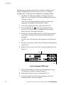
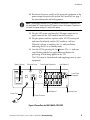
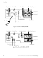
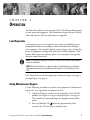
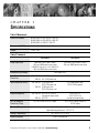
Powerware 9125
®
PowerPass
User's Guide
www.powerware.com
Requesting a Declaration of Conformity
Units that are labeled with a CE mark comply with the following harmonic standards and EU directives:
Harmonic Standards: EN 50091-1-1 and EN 50091-2
EU Directives: 73/23/EEC, Council Directive on equipment designed for use within certain voltage limits
93/68/EEC, Amending Directive 73/23/EEC
89/336/EEC, Council Directive relating to electromagnetic compatibility
92/31/EEC, Amending Directive 89/336/EEC relating to EMC
The EC Declaration of Conformity is available upon request for products with a CE mark. For copies of the EC
Declaration of Conformity, contact:
Powerware Corporation
Koskelontie 13
FIN-02920 Espoo
Finland
Phone: +358-9-452 661
Fax: +358-9-452 665 68
Class B EMC Statements
FCC Part 15
NOTE This equipment has been tested and found to comply with the limits for a Class B digital device, pursuant to
part 15 of the FCC Rules. These limits are designed to provide reasonable protection against harmful interference in a
residential installation. This equipment generates, uses and can radiate radio frequency energy and, if not installed and
used in accordance with the instructions, may cause harmful interference to radio communications. However, there is no
guarantee that interference will not occur in a particular installation. If this equipment does cause harmful interference to
radio or television reception, which can be determined by turning the equipment off and on, the user is encouraged to try
to correct the interference by one or more of the following measures:
Reorient or relocate the receiving antenna.
Increase the separation between the equipment and the receiver.
Connect the equipment into an outlet on a circuit different from that to which the receiver is connected.
Consult the dealer or an experienced radio/TV technician for help.
ICES-003
This Class B Interference Causing Equipment meets all requirements of the Canadian Interference Causing Equipment
Regulations ICES003.
Cet appareil numérique de la classe B respecte toutes les exigences du Reglement sur le matériel brouilleur du Canada.
Powerware and PowerPass are registered trademarks of Powerware Corporation.
Copyright 2000 Powerware Corporation, Raleigh, NC, USA. All rights reserved. No part of this document may be
reproduced in any way without the express written approval of Powerware Corporation.
CHAPTER
INSTALLATION
1
The PowerPass is designed to operate with a Powerware 9125
uninterruptible power system (UPS) and allows you to:
Replace or upgrade the UPS without losing power to your equipment
(see Using Maintenance Bypass" on page 7).
Provide surge protection if the UPS is not present.
Provide extra surge protection when the UPS is present.
Protect a laser printer against power surges without overloading the
UPS (not available on 2000 VA, 120V models).
Safety Warnings
IMPORTANT SAFETY INSTRUCTIONS
SAVE THESE INSTRUCTIONS. This manual contains important instructions that you
should follow during installation and maintenance of the UPS and batteries. Please
read all instructions before operating the equipment and save this manual for future
reference.
CAUTION
There are NO USER SERVICEABLE PARTS inside the PowerPass. All repairs and
service should be performed by AUTHORIZED SERVICE PERSONNEL ONLY.
To reduce the risk of fire or electric shock, install this UPS in a temperature and
humidity controlled, indoor environment, free of conductive contaminants. Ambient
temperature must not exceed 40°C (104°F). Do not operate near water or
excessive humidity (95% max).
Powerware® 9125 PowerPass® User's Guide 164201324 A Uncontrolled Copy
3
Installation
The following instructions describe the PowerPass installation only.
Follow the instructions in your Powerware 9125 User's Guide for
installing the UPS and optional Extended Battery Modules (EBMs).
1. Install the UPS and optional EBMs according to the user's
guide. Do not start up the UPS before installing the PowerPass.
Continue to Step 6.
If the UPS is already installed and operating, prepare your
equipment for shutdown and continue to Step 2.
2. Turn off the equipment that is connected to the UPS.
3. Press and hold the Off button for approximately three
seconds. The UPS switches to Standby mode and removes
power from the UPS output receptacles.
4. Unplug the UPS from the power outlet; the UPS shuts down in
five seconds. All front panel indicators flash briefly prior to
shutdown.
On 240V units, also disconnect the input power cord from the
UPS.
5. Disconnect the power cord(s) between the protected equipment
and the UPS.
6. Remove the two screws on the UPS rear panel and discard (see
Figure 1).
Screw
Screw
Figure 1. Removing the UPS Screws
7. Verify that both Bypass switches on the PowerPass are in the
UPS position (see Figure 2 through Figure 4).
8. Plug the PowerPass into the rear panel of the UPS.
9. Secure the PowerPass with the two mounting screws and
retaining washers. Do not overtighten.
4
Powerware® 9125 PowerPass® User's Guide 164201324 A Uncontrolled Copy
Installation
10. Reconnect the power cord(s) of the protected equipment to the
power output receptacles located on the PowerPass (see page 7
for more information on load segments).
NOTE The receptacle marked LASER is provided for laser printers. The power from
this outlet does NOT come from the UPS output, but from utility power. Therefore, in
the event of a power outage, this outlet loses power.
11. Plug the UPS power cord into the UPS-input connector (or
input connector for 240V models) on the PowerPass.
12. Plug the power cord into a power outlet. All UPS front panel
indicators flash briefly and the UPS conducts a selftest.
When the self-test is complete, the indicator flashes,
indicating the UPS is in Standby mode.
13. Start the UPS by pressing the On button. The indicator
stops flashing and the bar graph indicators display the
percentage of load being applied to the UPS.
The UPS is now in Normal mode and supplying power to your
equipment.
Bypass Switches
Mounting Screw
Power Output Receptacles
Load Segment 2
Laser Printer
Receptacle
Power Cord
Load Segment 1
Mounting Screw
UPS-Input Connector
Figure 2. PowerPass for 7001500 VA, 120V UPS
Powerware® 9125 PowerPass® User's Guide 164201324 A Uncontrolled Copy
5
Installation
Bypass Switches
Mounting Screw
Circuit Breakers
Power Output Receptacles
Load Segment 2
Load Segment 1
Circuit Breaker Access
Power Cord
Mounting Screw
UPS-Input Connector
Figure 3. PowerPass for 2000 VA, 120V UPS
Bypass Switches
Mounting Screw
Laser Printer Receptacle
Power Output Receptacles
Load Segment 2
Load Segment 1
Circuit Breaker
Access
Input Connector
Mounting Screw
Figure 4. PowerPass for 7002000 VA, 240V UPS
6
Powerware® 9125 PowerPass® User's Guide 164201324 A Uncontrolled Copy
CHAPTER
OPERATION
2
The PowerPass allows for the removal of the UPS while providing power
to your protected equipment. This Maintenance Bypass feature is useful
when replacing the UPS for maintenance or upgrades.
Load Segments
Load segments are sets of receptacles that can be controlled by power
management software, providing an orderly shutdown and startup of
your equipment. For example, during a power outage, you can keep key
pieces of equipment running while you turn off other equipment. This
feature allows you to save battery power. See your power management
software manual for details.
NOTE If the power management software is not used, the individual load segments
cannot be controlled.
NOTE When the PowerPass is in Bypass mode, all load segments are switched to
utility power and cannot be controlled until the PowerPass is switched back to the
UPS.
Each PowerPass has two load segments as shown in Figure 2 on page 5
through Figure 4 on page 6.
Using Maintenance Bypass
Use the following procedure to transfer your equipment to Maintenance
Bypass (AC Line operation) and remove the UPS:
1. Toggle both Bypass switches on the PowerPass to the BYPASS
position (see Figure 2 on page 5 through Figure 4 on page 6).
The PowerPass is now powering your equipment from utility
power.
2. Press and hold the Off button for approximately three
seconds. The UPS switches to Standby mode.
Powerware® 9125 PowerPass® User's Guide 164201324 A Uncontrolled Copy
7
Operation
3. If an optional EBM is installed, unplug the EBM cable from the
battery connector on the UPS rear panel.
4. 120V models only. Disconnect the UPS power cord from the
PowerPass UPS-input connector.
5. Loosen the two PowerPass mounting screws.
6. Remove the PowerPass from the UPS, being careful not to
loosen the power cords plugged into the PowerPass.
Use the following procedure to reinstall the UPS and transfer your
equipment from Maintenance Bypass (AC Line operation) to the UPS:
1. If an optional EBM is installed, reconnect the EBM cable to the
battery connector on the UPS rear panel.
2. 120V models only. Plug the UPS power cord into the PowerPass
UPS-input connector.
3. Plug the PowerPass into the rear panel of the UPS.
All UPS front panel indicators flash briefly and the UPS
conducts a selftest. When the self-test is complete, the indicator flashes, indicating the UPS is in Standby mode.
4. Tighten the two PowerPass mounting screws. Do not
overtighten.
5. Start the UPS by pressing the On button.
The indicator stops flashing.
6. Toggle both Bypass switches on the PowerPass to the UPS
position.
The bar graph indicators display the percentage of load being
applied to the UPS. The UPS is now in Normal mode and
supplying power to your equipment.
8
Powerware® 9125 PowerPass® User's Guide 164201324 A Uncontrolled Copy
CHAPTER
3
SPECIFICATIONS
Table 1. Mechanical
PowerPass Models
05146519-001 for 7001500 VA, 120V UPS
05146519-002 for 7002000 VA, 240V UPS
05146520-001 for 2000 VA, 120V UPS
Dimensions (WxDxH)
11.0" x 4.5" x 3.5" (27.9 x 11.4 x 8.9 cm)
Weight
2.5 lb (1.1 kg)
Table 2. Technical
Surge Supression
Electrostatic Discharge
120V Models
240V Models
180V MOVs across input L and N;
100 joule, 6500A peak current rating
320V MOVs each across L to G and N to G;
160 joule; 6500A peak current rating
320V MOVs across input L1 and L2;
160 joule, 6500A peak current rating
Withstands 25 kV
Input Connection to
PowerPass
7001500 VA: 6-ft, 5-15P power cord
2000 VA: 6-ft, 5-20P power cord
IEC 320-C14 input connector
Input Connection to UPS
7001500 VA: 5-15R mates with
UPS 5-15P power cord
2000 VA: 5-20R mates with
UPS 5-20P power cord
IEC-320 plug mates with
UPS IEC-320 receptacle
Output Receptacles
7001500 VA: (6) 5-15R; (1) 5-15R for
laser printer (unprotected)
2000 VA: (6) 5-15R
(6) IEC 320-C13;
(1) IEC 320-C13 for
laser printer (unprotected)
(2) 5-15P connect to UPS AC output
(2) IEC 320-C13 plugs connect to
UPS AC output
UPS AC Output to
PowerPass (Plug)
Operating Temperature
Storage Temperature
Relative Humidity
0°C to 40°C (32°F to 104°F)
Optimal battery performance: 25°C (77°F)
-20°C to 60°C (-4°F to 140°F)
596% noncondensing
Powerware® 9125 PowerPass® User's Guide 164201324 A Uncontrolled Copy
9
Specifications
10
Powerware® 9125 PowerPass® User's Guide 164201324 A Uncontrolled Copy
*164201324A*
164201324 A
12
Powerware® 9125 PowerPass® User's Guide 164201324 A Uncontrolled Copy