1
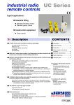
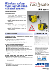
®
Eaton 9PX PowerPass Distribution Modules and Transformers
9PXTFMR5, 9PXPPDM2, 9PXTFMR11, and 9PXPPDM1
User's Guide
®
For use with 9PX 5000/6000/8000/11000 VA UPS Models
Class A EMC Statements
FCC Part 15
NOTE This equipment has been tested and found to comply with the limits for a Class A digital device, pursuant to
part 15 of the FCC Rules. These limits are designed to provide reasonable protection against harmful interference
when the equipment is operated in a commercial environment. This equipment generates, uses, and can radiate
radio frequency energy and, if not installed and used in accordance with the instruction manual, may cause harmful
interference to radio communications. Operation of this equipment in a residential area is likely to cause harmful
interference in which case the user will be required to correct the interference at his own expense.
EN 62040-2
Some configurations are classified under EN 62040-2 as “Class‐A UPS for Unrestricted Sales Distribution.” For
these configurations, the following applies:
WARNING
This is a Class A‐UPS Product. In a domestic environment, this product may cause radio interference, in which case,
the user may be required to take additional measures.
Eaton and PowerPass are registered trademarks of Eaton Corporation or its subsidiaries and affiliates. Phillips is a
registered trademark of Phillips Screw Company. All other trademarks are property of their respective companies.
ECopyright 2012–2014 Eaton Corporation, Raleigh, NC, USA. All rights reserved. No part of this document may be
reproduced in any way without the express written approval of Eaton Corporation.
Requesting a Declaration of Conformity
Units that are labeled with a CE mark comply with the following harmonized standards and EU directives:
S
Harmonized Standards: EN 62040-1 and EN 62040-2 (2006-6)
S
EU Directives:
2006/95/EC, Council Directive on equipment designed for use within certain voltage limits
2004/108/EC, Council Directive relating to electromagnetic compatibility
The EC Declaration of Conformity is available upon request for products with a CE mark. For copies of the EC
Declaration of Conformity, contact:
Eaton Power Quality SAS
110, Rue Blaise Pascal
38334 St ISMIER
FRANCE
Phone: +33 476 00 66 66
Special Symbols
The following are examples of symbols used on the UPS or accessories to alert you to important
information:
RISK OF ELECTRIC SHOCK - Indicates that a risk of electric shock is present and the
associated warning should be observed.
CAUTION: REFER TO OPERATOR'S MANUAL - Refer to your operator's manual for
additional information, such as important operating and maintenance
instructions.
This symbol indicates that you should not discard the UPS or the UPS batteries
in the trash. This product contains sealed, lead‐acid batteries and must be
disposed of properly. For more information, contact your local recycling/reuse or
hazardous waste center.
This symbol indicates that you should not discard waste electrical or electronic
equipment (WEEE) in the trash. For proper disposal, contact your local
recycling/reuse or hazardous waste center.
Table of Contents
1
2
3
4
5
Introduction . . . . . . . . . . . . . . . . . . . . . . . . . . . . . . . . . . . . . . . . . . . . . . . . . . . . . . . . .
1
Features . . . . . . . . . . . . . . . . . . . . . . . . . . . . . . . . . . . . . . . . . . . . . . . . . . . . . . . . . . . . . . . . . . . . . . . . . . .
Models . . . . . . . . . . . . . . . . . . . . . . . . . . . . . . . . . . . . . . . . . . . . . . . . . . . . . . . . . . . . . . . . . . . . . . . . . . . .
System Configuration Options . . . . . . . . . . . . . . . . . . . . . . . . . . . . . . . . . . . . . . . . . . . . . . . . . . . . . . . . . . . .
9PX PPDM Models . . . . . . . . . . . . . . . . . . . . . . . . . . . . . . . . . . . . . . . . . . . . . . . . . . . . . . . . . . . . . . . . .
9PX Transformer Models . . . . . . . . . . . . . . . . . . . . . . . . . . . . . . . . . . . . . . . . . . . . . . . . . . . . . . . . . . . . .
1
1
3
3
3
Safety . . . . . . . . . . . . . . . . . . . . . . . . . . . . . . . . . . . . . . . . . . . . . . . . . . . . . . . . . . . . . .
5
Safety Warnings . . . . . . . . . . . . . . . . . . . . . . . . . . . . . . . . . . . . . . . . . . . . . . . . . . . . . . . . . . . . . . . . . . . . .
5
Equipment Installation . . . . . . . . . . . . . . . . . . . . . . . . . . . . . . . . . . . . . . . . . . . . . . . .
7
Inspecting the Equipment . . . . . . . . . . . . . . . . . . . . . . . . . . . . . . . . . . . . . . . . . . . . . . . . . . . . . . . . . . . . . . .
Checking the Accessories . . . . . . . . . . . . . . . . . . . . . . . . . . . . . . . . . . . . . . . . . . . . . . . . . . . . . . . . . . . . . . .
Tower Setup . . . . . . . . . . . . . . . . . . . . . . . . . . . . . . . . . . . . . . . . . . . . . . . . . . . . . . . . . . . . . . . . . . . . . . . .
Rackmount Setup . . . . . . . . . . . . . . . . . . . . . . . . . . . . . . . . . . . . . . . . . . . . . . . . . . . . . . . . . . . . . . . . . . . .
Installing the Rails . . . . . . . . . . . . . . . . . . . . . . . . . . . . . . . . . . . . . . . . . . . . . . . . . . . . . . . . . . . . . . . . .
Installing the Cabinet . . . . . . . . . . . . . . . . . . . . . . . . . . . . . . . . . . . . . . . . . . . . . . . . . . . . . . . . . . . . . . .
7
7
9
10
11
12
Electrical Installation . . . . . . . . . . . . . . . . . . . . . . . . . . . . . . . . . . . . . . . . . . . . . . . . .
15
9PXPPDM2 Electrical Installation . . . . . . . . . . . . . . . . . . . . . . . . . . . . . . . . . . . . . . . . . . . . . . . . . . . . . . . . .
Requirements . . . . . . . . . . . . . . . . . . . . . . . . . . . . . . . . . . . . . . . . . . . . . . . . . . . . . . . . . . . . . . . . . . . .
Procedure . . . . . . . . . . . . . . . . . . . . . . . . . . . . . . . . . . . . . . . . . . . . . . . . . . . . . . . . . . . . . . . . . . . . . . .
9PXTFMR11 Electrical Installation . . . . . . . . . . . . . . . . . . . . . . . . . . . . . . . . . . . . . . . . . . . . . . . . . . . . . . . . .
Requirements . . . . . . . . . . . . . . . . . . . . . . . . . . . . . . . . . . . . . . . . . . . . . . . . . . . . . . . . . . . . . . . . . . . .
Procedure . . . . . . . . . . . . . . . . . . . . . . . . . . . . . . . . . . . . . . . . . . . . . . . . . . . . . . . . . . . . . . . . . . . . . . .
9PXPPDM1 and 9PXTFMR5 Electrical Installation . . . . . . . . . . . . . . . . . . . . . . . . . . . . . . . . . . . . . . . . . . . . . .
Requirements . . . . . . . . . . . . . . . . . . . . . . . . . . . . . . . . . . . . . . . . . . . . . . . . . . . . . . . . . . . . . . . . . . . .
Procedure . . . . . . . . . . . . . . . . . . . . . . . . . . . . . . . . . . . . . . . . . . . . . . . . . . . . . . . . . . . . . . . . . . . . . . .
16
16
17
20
20
21
23
23
25
Voltage Selection . . . . . . . . . . . . . . . . . . . . . . . . . . . . . . . . . . . . . . . . . . . . . . . . . . . .
27
9PXPPDM1 and 9PXPPDM2 Voltage Selection . . . . . . . . . . . . . . . . . . . . . . . . . . . . . . . . . . . . . . . . . . . . . . . .
Settings . . . . . . . . . . . . . . . . . . . . . . . . . . . . . . . . . . . . . . . . . . . . . . . . . . . . . . . . . . . . . . . . . . . . . . . .
Procedure . . . . . . . . . . . . . . . . . . . . . . . . . . . . . . . . . . . . . . . . . . . . . . . . . . . . . . . . . . . . . . . . . . . . . . .
9PXTFMR5 Voltage Selection . . . . . . . . . . . . . . . . . . . . . . . . . . . . . . . . . . . . . . . . . . . . . . . . . . . . . . . . . . . .
Settings . . . . . . . . . . . . . . . . . . . . . . . . . . . . . . . . . . . . . . . . . . . . . . . . . . . . . . . . . . . . . . . . . . . . . . . .
Procedure . . . . . . . . . . . . . . . . . . . . . . . . . . . . . . . . . . . . . . . . . . . . . . . . . . . . . . . . . . . . . . . . . . . . . . .
28
28
29
29
30
30
Eaton 9PXTFMR5, 9PXPPDM2, 9PXTFMR11, and 9PXPPDM1 User's Guide S P-164000200 Rev 4
i
TABLE OF CONTENTS
6
7
8
9
ii
9PXTFMR11 Voltage Selection . . . . . . . . . . . . . . . . . . . . . . . . . . . . . . . . . . . . . . . . . . . . . . . . . . . . . . . . . . .
Settings . . . . . . . . . . . . . . . . . . . . . . . . . . . . . . . . . . . . . . . . . . . . . . . . . . . . . . . . . . . . . . . . . . . . . . . .
Procedure . . . . . . . . . . . . . . . . . . . . . . . . . . . . . . . . . . . . . . . . . . . . . . . . . . . . . . . . . . . . . . . . . . . . . . .
32
32
33
Startup . . . . . . . . . . . . . . . . . . . . . . . . . . . . . . . . . . . . . . . . . . . . . . . . . . . . . . . . . . . . .
35
Startup with the UPS . . . . . . . . . . . . . . . . . . . . . . . . . . . . . . . . . . . . . . . . . . . . . . . . . . . . . . . . . . . . . . . . . .
Plug-Receptacle Connections . . . . . . . . . . . . . . . . . . . . . . . . . . . . . . . . . . . . . . . . . . . . . . . . . . . . . . . . . . . .
System Configuration Connections . . . . . . . . . . . . . . . . . . . . . . . . . . . . . . . . . . . . . . . . . . . . . . . . . . . . . . . .
35
37
40
Maintenance Bypass . . . . . . . . . . . . . . . . . . . . . . . . . . . . . . . . . . . . . . . . . . . . . . . . . .
45
Using Maintenance Bypass . . . . . . . . . . . . . . . . . . . . . . . . . . . . . . . . . . . . . . . . . . . . . . . . . . . . . . . . . . . . .
Return to Normal UPS Protection . . . . . . . . . . . . . . . . . . . . . . . . . . . . . . . . . . . . . . . . . . . . . . . . . . . . . . . . .
45
46
Specifications . . . . . . . . . . . . . . . . . . . . . . . . . . . . . . . . . . . . . . . . . . . . . . . . . . . . . . .
49
Specification Tables . . . . . . . . . . . . . . . . . . . . . . . . . . . . . . . . . . . . . . . . . . . . . . . . . . . . . . . . . . . . . . . . . .
Rear Panels . . . . . . . . . . . . . . . . . . . . . . . . . . . . . . . . . . . . . . . . . . . . . . . . . . . . . . . . . . . . . . . . . . . . . . . . .
49
52
Service and Support . . . . . . . . . . . . . . . . . . . . . . . . . . . . . . . . . . . . . . . . . . . . . . . . . .
55
Eaton 9PXTFMR5, 9PXPPDM2, 9PXTFMR11, and 9PXPPDM1 User's Guide S P-164000200 Rev 4
Chapter 1
Introduction
The Eaton® 9PX PowerPass Distribution Module (9PX PPDM) and 9PX
Transformer models are designed to operate as accessories with Eaton
9PX 5000/6000/8000/11000 VA uninterruptible power systems (UPSs).
Features
The 9PX PPDM and 9PX Transformer basic features are:
S Provide surge protection if the UPS is not present
S Provide extra surge protection when the UPS is present
S Replace or upgrade the UPS without losing power to the protected
equipment using the Maintenance Bypass feature (for 9PX PPDMs
only)
S Voltage selection for 208 Vac or 240 Vac input
S Choice of plug-receptacle or terminal-block wired models
S Variety of output outlets
S Breaker protection
S Bypass and voltage selection switches on selected models
Models
There are four Eaton 9PX PPDM and 9PX Transformer models:
S 9PXTFMR5
S 9PXPPDM2
S 9PXTFMR11
S 9PXPPDM1
Eaton 9PXTFMR5, 9PXPPDM2, 9PXTFMR11, and 9PXPPDM1 User's Guide S P-164000200 Rev 4
1
INTRODUCTION
Figure 1 illustrates front views of the 9PX PPDM and 9PX Transformer
models.
Front Cover with Center Cover Attached (all models)
208V
NORMAL
BYPASS
2
4
0
V
Front Cover with Center Cover Removed to Access Bypass Switch ( 9PX PPDMs only)
208V
UPS
2
4
0
V
B
Y
P
A
S
S
Front Cover with Center Cover Open to Access Voltage Selection Switch
(all models except 9PXTFMR11, which uses terminal-block wiring for voltage selection)
Figure 1. Front Cover and Operation Switches
2
Eaton 9PXTFMR5, 9PXPPDM2, 9PXTFMR11, and 9PXPPDM1 User's Guide S P-164000200 Rev 4
INTRODUCTION
System Configuration Options
Several system configuration offerings combine the 9PX
5000/6000/8000/11000 VA UPS models with other units in the 9PX
solution suite, including the 9PX PPDMs and 9PX Transformers, the 9PX
240V Extended Battery Module (EBM), and the external Maintenance
Bypass (MBP) accessories.
9PX PPDM Models
The 9PX PPDM models are combined with 5000 VA and 6000 VA 9PX
UPS in four system configurations:
S 9PXPPDM1 configured with a 5000 VA 9PX UPS
S 9PXPPDM1 configured with a 6000 VA 9PX UPS
S 9PXPPDM2 configured with a 5000 VA 9PX UPS
S 9PXPPDM2 configured with a 6000 VA 9PX UPS
9PX Transformer Models
The 9PX Transformer models are combined with 9PX
5000/6000/8000/11000 VA UPS models (as well as EBMs and MBPs) in
five system configurations:
S 9PXTFMR5 with a 5000 VA 9PX UPS
S 9PXTFMR5 with a 6000 VA 9PX UPS
S 9PXTFMR5 (as well as a 240V EBM and MBP) configured with an
8000 VA 9PX UPS
S 9PXTFMR5 (as well as a 240V EBM and MBP) configured with an
11000 VA 9PX UPS
S 9PXTFMR11 (as well as a 240V EBM) configured with an 11000 VA
9PX UPS
NOTE See “System Configuration Connections” on page 40 for illustrations of the system
configurations.
Eaton 9PXTFMR5, 9PXPPDM2, 9PXTFMR11, and 9PXPPDM1 User's Guide S P-164000200 Rev 4
3
INTRODUCTION
4
Eaton 9PXTFMR5, 9PXPPDM2, 9PXTFMR11, and 9PXPPDM1 User's Guide S P-164000200 Rev 4
Chapter 2
Safety
Safety Warnings
IMPORTANT SAFETY INSTRUCTIONS
SAVE THESE INSTRUCTIONS
This manual contains important instructions that you should follow during installation and
maintenance of the Eaton 9PX PowerPass Distribution Modules (PPDMs), 9PX Transformers,
and 9PX UPS. Please read all instructions before operating the equipment and save this
manual for future reference.
DANGER
The UPS contains LETHAL VOLTAGES. All repairs and service should be performed by
AUTHORIZED SERVICE PERSONNEL ONLY. There are NO USER SERVICEABLE PARTS
inside the UPS.
CAUTION
S To reduce the risk of fire or electric shock, install this UPS in a temperature and humidity
controlled, indoor environment, free of conductive contaminants. Ambient temperature
must not exceed 40°C (104°F). Do not operate near water or excessive humidity
(95% maximum).
S For models with terminal-block wired outputs (9PXPPDM2 and 9PXTFMR11), overcurrent
protection for the output AC circuit(s) is to be provided by others.
S For pluggable equipment (9PXPPDM1 and 9PXTFMR5), the socket-outlet shall be
installed near the equipment and shall be easily accessible.
S Disconnection Device. For 9PXPPDM2, a disconnect switch shall be provided by others
for AC input and output circuit.
S Disconnection Device. For 9PXTFMR11, the disconnection device of the UPS used with
this power distribution module also serves as the AC input disconnection device of this
power distribution module. A disconnect switch shall be provided by others for AC output
circuit.
S Do not overload the 9PX PPDM or 9PX Transformers. For 120V output voltage, the output
of L1 or L2 can only be half-loaded.
Eaton 9PXTFMR5, 9PXPPDM2, 9PXTFMR11, and 9PXPPDM1 User's Guide S P-164000200 Rev 4
5
SAFETY
6
Eaton 9PXTFMR5, 9PXPPDM2, 9PXTFMR11, and 9PXPPDM1 User's Guide S P-164000200 Rev 4
Chapter 3
Equipment Installation
This chapter provides installation instructions for the Eaton 9PX
PowerPass Distribution Modules (PPDMs) and 9PX Transformers as
follows:
S Equipment and accessory kit inspection
S Tower configuration setup
S Rack configuration setup
Inspecting the Equipment
If any equipment has been damaged during shipment, keep the shipping
cartons and packing materials for the carrier or place of purchase and file
a claim for shipping damage. If you discover damage after acceptance,
file a claim for concealed damage.
To file a claim for shipping damage or concealed damage: 1) File with
the carrier within 15 days of receipt of the equipment; 2) Send a copy of
the damage claim within 15 days to your service representative.
Checking the Accessories
NOTE Packaging must be destroyed according to waste management standards. Recycling
icons are displayed for easy selection.
Verify that the accessory items listed in Table 1 are included with the
9PX PPDM and 9PX Transformers.
Eaton 9PXTFMR5, 9PXPPDM2, 9PXTFMR11, and 9PXPPDM1 User's Guide S P-164000200 Rev 4
7
EQUIPMENT INSTALLATION
Table 1. Accessories
Item
Description
(1) Manual
(2) Rails and mounting screws for rackmount cabinet
installation in standard 19-inch rack bays, in accessory
box
(1) Joining bracket and mounting screws for tower
configuration, in the accessory box
(2) Mounting brackets and mounting screws for
rackmount cabinet installation, in the accessory box
9PXTFMR11 models only.
(1) Transformer cable used from UPS Output to
Transformer Input, in the accessory bag
9PXPPDM2 and 9PXTFMR11 models only.
(2) Cable glands used as strain relief for hardwired cables
between the UPS and the 9PXPPDM2 or 9PXTFMR11, in
the accessory bag
Table 2 lists the tools that are needed to install the 9PX PPDM and 9PX
Transformers.
Table 2. Installation Tools
Item
Description
S Phillips® cross-head screwdriver
S Flat-head screwdriver
8
Eaton 9PXTFMR5, 9PXPPDM2, 9PXTFMR11, and 9PXPPDM1 User's Guide S P-164000200 Rev 4
EQUIPMENT INSTALLATION
Tower Setup
CAUTION
S DO NOT install the 9PX PPDMs and 9PX Transformers in a hermetically-closed
environment without any exchange of air.
S The 9PX PPDMs and 9PX Transformers are heavy (see the Specifications chapter).
A minimum of two people are required to lift the cabinets.
NOTE The order of a tower installation, from left to right, is the 9PX PPDM or 9PX
Transformer, 9PX EBM, and the 9PX UPS.
To set up a tower configuration:
1.
Do this only if the UPS is already installed and operating: Shut
down the UPS before installing a 9PX PPDM or 9PX Transformer.
Refer to shutdown instructions in the appropriate 9PX UPS user's
guide for your system configuration.
NOTE Eaton recommends a minimum of 150 mm (5.9”) free space behind the UPS rear
panel.
2.
Position the cabinet upright. Turn the Eaton logo to align with the
top of the cabinet. Ensure additional cabinets are upright.
3.
Group the cabinets in the correct order.
NOTE Joining brackets are required to stabilize the upright cabinets in installations with
two or more cabinets. A joining bracket is provided in the 9PX PPDM or 9PX Transformer
accessory box in the shipping carton.
NOTE If you are adding a cabinet to an existing tower configuration, only add a single
joining bracket between the 9PX PPDM or 9PX Transformer and the next cabinet in the
configuration.
4.
Locate the joining bracket in the rail kit box.
5.
Align each joining bracket with the adjacent cabinet screw holes
and secure with the supplied screws (see Figure 2).
Eaton 9PXTFMR5, 9PXPPDM2, 9PXTFMR11, and 9PXPPDM1 User's Guide S P-164000200 Rev 4
9
EQUIPMENT INSTALLATION
Joining Brackets
Figure 2. Joining Brackets (9PXTFMR11, 9PX 240V EBM, and 9PX 11k UPS
shown)
6.
Continue to “Electrical Installation” on page 15.
Rackmount Setup
NOTE The order of a rackmount installation, from top to bottom, is the 9PX UPS, 9PX EBM,
and the 9PX PPDM or 9PX Transformer.
NOTE First, install the rails in the rack. Then, install the cabinet on the rails.
10
Eaton 9PXTFMR5, 9PXPPDM2, 9PXTFMR11, and 9PXPPDM1 User's Guide S P-164000200 Rev 4
EQUIPMENT INSTALLATION
Installing the Rails
To install the rails in the rack:
1.
Locate the rails and the mounting hardware in the rail kit accessory
box.
2.
Locate the position where you will install the 9PX PPDM or 9PX
Transformer. (Install below the EBM if installed in this configuration,
or below the UPS if the EBM is not installed in this configuration.)
3.
Place the rails on the inside of the rack posts with the cabinet
mounting flanges facing inside the rack. The L (Left) or R (Right)
letter on the side of the rail should also face inside the rack (see
Figure 3).
4.
Slide the rail to fit between the vertical rack posts.
5.
Secure each rail to the front and rear of the rack with two
M6 12 mm screws (see Figure 3).
FRONT
Rail-mounting
Screw Positions
REAR
Rail-mounting
Screw Positions
Figure 3. Attaching the Rails
6.
Continue to the next section, “Installing the Cabinet.”
Eaton 9PXTFMR5, 9PXPPDM2, 9PXTFMR11, and 9PXPPDM1 User's Guide S P-164000200 Rev 4
11
EQUIPMENT INSTALLATION
Installing the Cabinet
To install the cabinet on the rails:
1.
Do this only if the UPS is already installed and operating: Shut
down the UPS before installing a 9PX PPDM or 9PX Transformer.
Refer to shutdown instructions in the appropriate 9PX UPS user's
guide for your system configuration.
2.
Place the cabinet on a flat, stable surface with the front of the
cabinet facing you.
3.
Align the mounting brackets with the screw holes on the side of the
cabinet. Install the mounting brackets (see Figure 4).
Rack-mounting
Bracket
Figure 4. Installing Mounting Brackets
4.
12
Set the rear of the cabinet on the cabinet mounting flanges and
slide the cabinet into the rack (see Figure 5).
Eaton 9PXTFMR5, 9PXPPDM2, 9PXTFMR11, and 9PXPPDM1 User's Guide S P-164000200 Rev 4
EQUIPMENT INSTALLATION
208V
24
0V
Figure 5. Installing the Cabinet in the Rack
5.
Secure the front of the cabinet to the rack with two M6x12 mm
round-head screws. Note the position of the screws in the
installation front view (see Figure 6).
Two M6x12
Cabinet-mounting
Bracket Screws
UPS
Two M6x12
Rail-mounting
Screws
EBM
9PX
Transformer
or 9PX PPDM
Figure 6. Cabinet installed in Rack (Front view)
6.
Continue to “Electrical Installation” on page 15.
Eaton 9PXTFMR5, 9PXPPDM2, 9PXTFMR11, and 9PXPPDM1 User's Guide S P-164000200 Rev 4
13
EQUIPMENT INSTALLATION
14
Eaton 9PXTFMR5, 9PXPPDM2, 9PXTFMR11, and 9PXPPDM1 User's Guide S P-164000200 Rev 4
Chapter 4
Electrical Installation
This chapter provides electrical installation instructions for the Eaton 9PX
PowerPass Distribution Modules (PPDMs) and 9PX Transformers.
WARNING
Risk of electrical shock. Only qualified service personnel (such as a licensed electrician) shall
perform the electrical installation.
CAUTION
S To reduce the risk of fire, unit input connect only to a circuit provided with branch circuit
overcurrent protection (30A for 9PXPPDM1, 9PXPPDM2, and 9PXTFMR5; 80A for
9PXTFMR11) in accordance with the National Electrical Code® (NEC®), ANSI/NFPA 70 or
your local electrical code.
S For 9PXPPDM2 and 9PXTFMR11 only: For models with terminal-block wired outputs,
overcurrent protection for the output AC circuit(s) is to be provided by others.
S For 9PXPPDM1 and 9PXTFMR5 only: For pluggable equipment:, the socket-outlet shall be
installed near the equipment and shall be easily accessible.
S Disconnection Device. For 9PXPPDM2, a disconnect switch shall be provided by others
for AC input and output circuit.
S Disconnection Device. For 9PXTFMR11, the disconnection device of the UPS used with
this power distribution module also serves as the AC input disconnection device of this
power distribution module. A disconnect switch shall be provided by others for AC output
circuit.
NOTE Do not make unauthorized changes to the 9PX UPS, 9PX PPDM, or 9PX Transformer
models. Otherwise, damage may occur to your equipment and void your warranty.
Table 3 lists the recommended input circuit breaker rating for 9PX
PPDMs.
Table 3. Recommended Input Circuit Breaker Rating for 9PX PPDMs
9PX PPDM
Input Circuit Breaker Rating
9PXPPDM1
30A
9PXPPDM2
30A
Eaton 9PXTFMR5, 9PXPPDM2, 9PXTFMR11, and 9PXPPDM1 User's Guide S P-164000200 Rev 4
15
ELECTRICAL INSTALLATION
9PXPPDM2 Electrical Installation
This section provides terminal block wiring requirements and electrical
installation procedures for the 9PXPPDM2 model.
Requirements
The 9PXPPDM2 model requires a dedicated branch circuit that meets
the following requirements:
S 30A circuit with short circuit and overcurrent protection
S 208/240 Vac
S Single phase
S 50/60 Hz
S Breaker must be wall-mounted and readily accessible to the operator
S Flexible metal conduit (recommended for ease of service and
maintenance)
Figure 7 shows the 9PXPPDM2 block diagram. The 9PXPPDM2 I/O
terminal block is hardwired.
Voltage Selection
30A CB
L1
30A MBP
To UPS
Output
120
30A
L6-30P
N
G
240
Transformer
AC Output
From UPS
L6-30R
Input
L2
G
G
Transformer
L1
L2
G
TB (x3)
AC Input
TB (x4)
Figure 7. 9PXPPDM2 Block Diagram
16
Eaton 9PXTFMR5, 9PXPPDM2, 9PXTFMR11, and 9PXPPDM1 User's Guide S P-164000200 Rev 4
120
ELECTRICAL INSTALLATION
Procedure
To wire the I/O terminal block for the 9PXPPDM2:
1.
Switch off utility power at the distribution point where the
9PXPPDM2 model will be connected. Be absolutely sure there is no
power.
2.
Verify that the output circuit breaker is in the OFF position (see
“Rear Panels” on page 52).
3.
On the front cover, unsnap and remove the square center cover.
4.
Verify that the bypass switch is in the UPS (normal) position:
S If the bypass switch is set to UPS, replace the square center
cover and go to Step 5.
S If the bypass switch is set on Bypass, turn the bypass switch to
the UPS (normal) position (see Figure 8). Replace the square
center cover and go to Step 5.
208V
NORMAL
BYPASS
24
0V
Figure 8. Resetting the Switch to UPS (Normal)
5.
Use a Phillips-head screwdriver to remove the screw to detach the
terminal block cover. Retain the cover and screw (see Figure 9).
Eaton 9PXTFMR5, 9PXPPDM2, 9PXTFMR11, and 9PXPPDM1 User's Guide S P-164000200 Rev 4
17
ELECTRICAL INSTALLATION
NORMALAC SOURCE
Punch Out
Knock-out
Holes
OUTPUT
Normal AC
Source
NORMAL AC SOURCE
Remove Screw
Output
OUTPUT
Figure 9. Removing the Terminal Block Cover
6.
Punch out the pre-cut knock-out holes for the input and output
conduit.
7.
Pull the input and output wires through separate conduit, leaving
approximately 0.5m (2 ft) of exposed wire. Attach a flexible metal
fitting to the end of each conduit.
8.
On the UPS, insert each conduit through a wiring access entry.
Strip 9 mm (0.35”) of insulation from the end of each incoming wire.
9.
On the 9PXPPDM2 terminal block, wire the UPS connections
(terminals 1–3) and attach the cable gland to the panel (see
Figure 10 and Table 4).
10. To wire the load connections (terminals 4–6), observe the following:
S Connect 4 and 6 (line to line) for 240V
S Connect 5 and 6 (line to neutral) for 120V
S Connect 4 and 5 (line to neutral) for 120V
11. Connect 7 (ground).
18
Eaton 9PXTFMR5, 9PXPPDM2, 9PXTFMR11, and 9PXPPDM1 User's Guide S P-164000200 Rev 4
Source Input Line 2
AC SOURCE
L-1
N( L-2)
Input Ground
NORMAL
ELECTRICAL INSTALLATION
Output Line 1
Output Neutral
Load Connections
(4 to 7)
Output Line 2
Output Ground
2
3
L-1
UPS Connections
(1 to 3)
1
4
OUTPUT
N
L-2
Source Input Line 1
5
6
120V
240V
120V
7
Figure 10. 9PXPPDM2 I/O Terminal Block
Table 4. 9PXPPDM2 Wiring Specifications
Terminal
Position
9PXPPDM2 Wire Function
1
Source Input Line 1
2
Source Input Line 2
3
Input Ground
4
Output Line 1
5
Output Neutral
6
Output Line 2
7
Output Ground
Terminal Wire
Size Rating*
Tightening
Torque
10–16 mm2
(8–6 AWG)
6–16 mm2
(10–6 AWG)
10–16 mm2
(8–6 AWG)
1.8 ±0.22 Nm
(16 ±2 lb in)
6–16 mm2
(10–6 AWG)
* Use 8 AWG for 9PXPPDM2 (75_C copper wire minimum).
12. Attach the cable gland to the panel.
13. Replace the terminal block cover and secure with screw.
14. Continue to “Voltage Selection” on page 27 to set the voltage
selection.
Eaton 9PXTFMR5, 9PXPPDM2, 9PXTFMR11, and 9PXPPDM1 User's Guide S P-164000200 Rev 4
19
ELECTRICAL INSTALLATION
9PXTFMR11 Electrical Installation
This section provides terminal block wiring requirements and electrical
installation procedures for the 9PXTFMR11 model.
Requirements
The 9PXTFMR11 model requires a dedicated branch circuit that meets
the following requirements:
S 80A circuit with short circuit and overcurrent protection
S 208/240 Vac
S Single phase
S 50/60 Hz
S Breaker must be wall-mounted and readily accessible to the operator
S Flexible metal conduit (recommended for ease of service and
maintenance)
Figure 11 shows the 9PXTFMR11 block diagram. The 9PXTFMR11 I/O
terminal block is hardwired. The voltage selection terminal block must
be wired with flexible wiring.
50A CB
Voltage
Selection
240
L1
208
N
120
240
Transformer
AC Output
L1
30A CB
30A CB
L2
20A CB
AC Input
20A CB
Transformer
L2
G
G
TB (x6)
TB (x4)
(To UPS
Output)
5-20R
(x4)
5-20R
(x4)
L14-30R
L14-30R
G
Figure 11. 9PXTFMR11 Block Diagram
20
Eaton 9PXTFMR5, 9PXPPDM2, 9PXTFMR11, and 9PXPPDM1 User's Guide S P-164000200 Rev 4
120
ELECTRICAL INSTALLATION
Procedure
To wire the I/O terminal block for the 9PXTFMR11:
1.
Switch off utility power at the distribution point where the
9PXTFMR11 model will be connected. Be absolutely sure there is
no power.
2.
Verify that the output circuit breaker is in the OFF position (see
“Rear Panels” on page 52).
3.
Use a Phillips-head screwdriver to remove the screw that secures
the terminal block cover. Remove the cover. Retain the cover and
screw (see Figure 12).
Normal AC
Source
NORMAL AC SOURCE
Remove Screw
NORMAL AC SOURCE
Output
Punch Out
Knock-out
Holes
OUTPUT
208V~/240V~
SELEC T
OUTPUT
Figure 12. Removing the Terminal Block Cover
4.
Punch out the pre-cut knock-out holes for the input and output
conduit.
5.
Pull the input and output wires through separate conduit, leaving
approximately 0.5m (2 ft) of exposed wire. Attach a flexible metal
fitting to the end of each conduit.
6.
On the UPS, insert each conduit through a wiring access entry.
Strip 9 mm (0.35”) of insulation from the end of each incoming wire.
7.
On the 9PXTFMR11 terminal block, wire the UPS connections 1-3
and attach the cable gland to the panel (see Figure 13 and Table 5).
Eaton 9PXTFMR5, 9PXPPDM2, 9PXTFMR11, and 9PXPPDM1 User's Guide S P-164000200 Rev 4
21
ELECTRICAL INSTALLATION
8.
Do you want to wire the connections for the load or use the
receptacles?
S For receptacles, go to Step 13.
S For wired connections, go to Step 9.
9.
To wire the load connections (terminals 4–6), observe the following:
S Connect 4 and 6 (line to line) for 240V
S Connect 5 and 6 (line to neutral) for 120V
S Connect 4 and 5 (line to neutral) for 120V
Input Ground
Output Line 1
Output Neutral
Load Connections
(4 to 7)
Output Line 2
Output Ground
NORMAL AC SOURCE
N( L-2)
L-1
Source Input Line 2
UPS Connections
(1 to 3)
1
4
OUTPUT
N
L-2
Source Input Line 1
L-1
10. Connect 7 (output ground).
2
3
120V
240V
5
6
120V
7
Figure 13. 9PXTFMR11 I/O Terminal Block
22
Eaton 9PXTFMR5, 9PXPPDM2, 9PXTFMR11, and 9PXPPDM1 User's Guide S P-164000200 Rev 4
ELECTRICAL INSTALLATION
Table 5. 9PXTFMR11 Wiring Specifications
Terminal
Position
Wire Function
9PXTFMR11
Terminal Wire
Size Rating*
1
Source Input Line 1
6 AWG
2
Source Input Line 2
6 AWG
3
Input Ground
6 AWG
4
Output Line 1
6 AWG
5
Output Neutral
6 AWG
6
Output Line 2
6 AWG
7
Output Ground
6 AWG
Tightening
Torque
1.8 ±0.22 Nm
(16 ±2 lb in)
* Use 6 AWG for 9PXTFMR11 (90_C copper wire minimum).
11. Attach the cable gland to the panel.
12. Replace the terminal block cover and secure with screw.
13. Continue to “Voltage Selection” on page 27 to set the voltage
selection.
9PXPPDM1 and 9PXTFMR5 Electrical Installation
This section provides terminal block wiring requirements and electrical
installation procedures for the 9PXPPDM1 and the 9PXTFMR5 models.
Requirements
CAUTION
The 9PXPPDM1 and 9PXTFMR5 models require a 30A circuit with short circuit and
overcurrent protection.
Eaton 9PXTFMR5, 9PXPPDM2, 9PXTFMR11, and 9PXPPDM1 User's Guide S P-164000200 Rev 4
23
ELECTRICAL INSTALLATION
Figure 14 shows the 9PXPPDM1 block diagram.
Voltage Selection
30A CB
L1
30A MB
To UPS
Output
120
30A
L6-30P
N
G
Transformer
240 AC Output
L1
Transformer
AC Input L6-30P
L2
G
5-20R
(x3)
L2 120
20A CB
G
20A CB
From UPS L6-30R
Input
5-20R
(x3)
L6-30R
L14-30R
Figure 14. 9PXPPDM1 Block Diagram
24
Eaton 9PXTFMR5, 9PXPPDM2, 9PXTFMR11, and 9PXPPDM1 User's Guide S P-164000200 Rev 4
ELECTRICAL INSTALLATION
Figure 15 shows the 9PXTFMR5 block diagram.
Voltage Selection
30A CB
L1
120
N
Transformer
AC Output
30A
5-20R
(x3)
5-20R
(x3)
5-20R
(x3)
20A CB
20A CB
20A CB
20A CB
Transformer
L1
AC Input
L6-30P
(To UPS
L2
Output)
G
5-20R 5-20R
(x3)
(x3)
L2
120
5-20R G
(x3)
Figure 15. 9PXTFMR5 Block Diagram
Procedure
For the 9PXPPDM1 and 9PXTFMR5 plug-receptacle models:
1.
Verify that the output circuit breaker is in the OFF position (see
“Rear Panels” on page 52).
2.
9PXTFMR5 only. Go to Step 5.
3.
9PXPPDM1 only. On the front cover, unsnap and remove the
square center cover.
Eaton 9PXTFMR5, 9PXPPDM2, 9PXTFMR11, and 9PXPPDM1 User's Guide S P-164000200 Rev 4
25
ELECTRICAL INSTALLATION
4.
Verify that the bypass switch is in the UPS (normal) position.
S If the bypass switch is set to UPS, replace the square center
cover and go to Step 5.
S If the bypass switch is set on Bypass instead, turn the bypass
switch to the UPS (normal) position (see Figure 16). Replace the
square center cover and go to Step 5.
208V
NORMAL
BYPASS
24
0V
Figure 16. Resetting the Switch to UPS (Normal)
5.
26
Continue to “Voltage Selection” on page 27 to set the voltage
selection.
Eaton 9PXTFMR5, 9PXPPDM2, 9PXTFMR11, and 9PXPPDM1 User's Guide S P-164000200 Rev 4
Chapter 5
Voltage Selection
This chapter provides the following voltage selection information for the
Eaton 9PX PowerPass Distribution Modules (PPDMs) and 9PX
Transformers.
NOTE In most applications, the voltage setting does NOT need changing.
All high voltage outlets, except the L14-30, use the UPS output voltage.
The L14-30 and all low voltage receptacles use the transformer, and the
voltage switch determines the voltage.
NOTE The 9PXTFMR11 does not have a voltage switch. The voltage must be wired in the
voltage selection terminal block.
When the voltage selection is set to the 240V position with 240V input,
the output voltage is 240/120V. When the voltage selection is set to
208V with 208V input, the output voltage is 240/120V.
See the input/output (I/O) voltage settings tables and specific
procedures in this chapter to set the voltage selection for your
equipment.
Eaton 9PXTFMR5, 9PXPPDM2, 9PXTFMR11, and 9PXPPDM1 User's Guide S P-164000200 Rev 4
27
VOLTAGE SELECTION
9PXPPDM1 and 9PXPPDM2 Voltage Selection
This section provides voltage settings and the voltage selection
switching procedure for the 9PXPPDM1 and 9PXPPDM2 models.
Settings
See Table 6 for 9PXPPDM1 voltage settings. See Table 7 for 9PXPPDM2
voltage settings.
Table 6. 9PXPPDM1 I/O Voltage Settings
9PXPPDM1 Output Voltage
Input Voltage
(from UPS)
208V Switch Position
Default 240V Switch Position
L6-30R
5-20R
L14-30R
L6-30R
5-20R
L14-30R
200
231
115
231/115
200
100
200/100
208
240
120
240/120
208
104
208/104
220
254
127
254/127
220
110
220/110
230
265
133
265/133
230
115
230/115
240
277
138
277/138
240
120
240/120
Table 7. 9PXPPDM2 I/O Voltage Settings
9PXPPDM2 Output Voltage
Input Voltage
(from UPS)
28
208V Switch Position
240V Switch Position
HV
LV
HV
LV
200
231
115
200
100
208
240
120
208
104
220
254
127
220
110
230
265
133
230
115
240
277
138
240
120
Eaton 9PXTFMR5, 9PXPPDM2, 9PXTFMR11, and 9PXPPDM1 User's Guide S P-164000200 Rev 4
VOLTAGE SELECTION
Procedure
To change the 9PXPPDM1 or 9PXPPDM2 voltage switch position:
1.
On the 9PXPPDM1 or 9PXPPDM2 front cover, unsnap and remove
the square center cover.
2.
Remove and retain the two left-side Phillips-head screws that
secure the front cover (see Figure 17).
Remove Screws
208V
NORMAL BYPASS
24
0V
Figure 17. Remove the Front Cover Screws
3.
Open the front cover from the left side (see Figure 18).
208V
UPS
2
4
0
V
BY
PA
SS
Figure 18. Open the Front Cover
4.
Turn the switch to the selected voltage.
5.
Close the front cover and secure it with the two Phillips-head
screws.
6.
Replace the square center cover.
7.
For startup with the UPS, go to Chapter 4 “Startup” on page 35.
Eaton 9PXTFMR5, 9PXPPDM2, 9PXTFMR11, and 9PXPPDM1 User's Guide S P-164000200 Rev 4
29
VOLTAGE SELECTION
9PXTFMR5 Voltage Selection
This section provides voltage settings and the voltage selection
switching procedure for the 9PXTFMR5 model.
Settings
See Table 8 for 9PXTFMR5 voltage settings.
Table 8. 9PXTFMR5 I/O Voltage Settings
9PXTFMR5 Output Voltage
Input Voltage
(from UPS)
208V Switch Position
240V Switch Position
5-20R
5-20R
200
115
100
208
120
104
220
127
110
230
133
115
240
138
120
250
144
125
Procedure
To change the 9PXTFMR5 voltage switch position:
1.
On the 9PXTFMR5 front cover, unsnap and remove the square
center cover.
2.
Remove and retain the two left-side Phillips-head screws that
secure the front cover (see Figure 19).
Remove Screws
208V
24
0V
Figure 19. Remove the Front Cover Screws
30
Eaton 9PXTFMR5, 9PXPPDM2, 9PXTFMR11, and 9PXPPDM1 User's Guide S P-164000200 Rev 4
VOLTAGE SELECTION
3.
Open the front cover from the left side (see Figure 20).
208V
UPS
2
4
0
V
BY
PA
SS
Figure 20. Open the Front Cover
4.
Turn the switch to the selected voltage.
5.
Close the front cover and secure it with the two Phillips-head
screws.
6.
Replace the square center cover.
7.
For startup with the UPS, go to Chapter 4 “Startup” on page 35.
Eaton 9PXTFMR5, 9PXPPDM2, 9PXTFMR11, and 9PXPPDM1 User's Guide S P-164000200 Rev 4
31
VOLTAGE SELECTION
9PXTFMR11 Voltage Selection
This section provides voltage settings and the voltage selection terminal
block wiring procedure for the 9PXTFMR11 model.
Settings
See Table 9 for 9PXTFMR11 voltage selection terminal block settings.
See Table 10 for 9PXTFMR11 plug-receptacle voltages.
Table 9. 9PXTFMR11 I/O Voltage Settings for Voltage Selection Terminal Block
9PXTFMR11 Output Voltage
Input Voltage
(from UPS)
208V Setting
240V Setting
HV
LV
HV
LV
200
231
115
200
100
208
240
120
208
104
220
254
127
220
110
230
265
133
230
115
240
277
138
240
120
250
288
144
250
125
Table 10. 9PXTFMR11 I/O Voltage Settings for Plug Receptacles
9PXTFMR11 Output Voltage
Input Voltage
(from UPS)
32
208V Setting
240V Setting
5-20R
L14-30R
5-20R
L14-30R
200
116
231/115
100
200/100
208
121
240/120
104
208/104
220
128
254/127
110
220/110
230
134
265/133
115
230/115
240
139
277/138
120
240/120
250
144
288/144
125
250/125
Eaton 9PXTFMR5, 9PXPPDM2, 9PXTFMR11, and 9PXPPDM1 User's Guide S P-164000200 Rev 4
VOLTAGE SELECTION
Procedure
To wire the 9PXTFMR11 voltage selection:
1.
On the 9PXTFMR11 rear panel, remove and retain the Phillips-head
screw and voltage selection terminal block cover (see Figure 21).
NORMA
L AC SOURCE
NORMALAC SOURCE
Normal AC
Source
Remove
Screw
OUTPUT
208V~/240V~
SELEC T
Output
OUTPUT
Figure 21. Remove the Voltage Selection Terminal Block Cover
2.
On the voltage selection terminal block, use 6 AWG wire to connect
a jumper from the middle terminal to either the 208V (left) or 240V
(right) terminal (see Figure 22):
208V /240V SELECTION
Connect Terminals
1
2
for
208V
Connect Terminals
1
208V
2
3
2
3
for
240V
240V
Figure 22. Wire Selected Voltage
3.
Replace the voltage selection terminal block cover and secure it
with the Phillips-head screw.
4.
For startup with the UPS, go to Chapter 4 “Startup” on page 35.
Eaton 9PXTFMR5, 9PXPPDM2, 9PXTFMR11, and 9PXPPDM1 User's Guide S P-164000200 Rev 4
33
VOLTAGE SELECTION
34
Eaton 9PXTFMR5, 9PXPPDM2, 9PXTFMR11, and 9PXPPDM1 User's Guide S P-164000200 Rev 4
Chapter 6
Startup
This chapter provides instructions for starting up Eaton 9PX PowerPass
Distribution Modules (PPDMs) or 9PX Transformers with a 9PX
5000/6000/8000/11000 VA UPS. System configuration connection
diagrams are also provided.
Startup with the UPS
To start up a 9PX PPDM or 9PX Transformer with the UPS:
NOTE If you are installing a remote power-off (RPO) switch, install the switch before
powering on the UPS. Refer to “RPO Installation” in the 9PX UPS user's guide for instructions.
NOTE Refer to the 9PX UPS user's guide for recommended upstream protection. For
European models, also refer to the recommendations for downstream protection.
NOTE Before startup, refer to the 9PX UPS/EBM/MBP user's guides for additional
configuration information.
NOTE To change the UPS default settings, refer to “Display Functions” in the UPS user's
guide. Refer to the UPS user's guide for UPS operation.
1.
Ensure that the upstream circuit breaker is OFF.
2.
Plug the input and output cords of the 9PX PPDM or 9PX
Transformer model into the input and output connectors on the
UPS (see “System Configuration Connections” on page 40 for
connection illustrations).
3.
Verify that the UPS internal battery connector is connected (refer to
the UPS/EBM user's guide).
4.
For 8k or 11k EBM only. Switch all battery circuit breakers to the
ON ( | ) position (refer to the UPS/EBM user's guide).
Eaton 9PXTFMR5, 9PXPPDM2, 9PXTFMR11, and 9PXPPDM1 User's Guide S P-164000200 Rev 4
35
STARTUP
5.
Ensure that the main circuit breaker on the 9PX PPDM or 9PX
Transformer is ON.
The equipment is powered by utility power, but not protected by
the UPS.
NOTE For 9PX PPDMs only. If the bypass switch is set to Bypass, the load is powered by
AC source, but still is not protected by the UPS.
CAUTION
The 9PX PPDM output circuit breaker (disconnect switch) disconnects power to the output on
the 9PX PPDM rear panel, but does NOT shut off power to the UPS (opening the upstream
protection would be required).
Batteries are recharging. An eight-hour recharge period is necessary
to get full backup time.
6.
button until you hear the UPS beep
Press and hold the
(approximately three seconds).
After the UPS is turned on, it conducts a self-test and enters
indicator remains on, indicating that power
Normal mode. The
is available to your equipment.
7.
Confirm the UPS output voltage through the front panel and verify
that it matches the 9PX PPDM or 9PX Transformer output voltage.
For example, if the input to the UPS is 208V, then voltage selection
should be 208V. (For voltage settings and voltage selection
procedures for all models, see “Voltage Selection” on page 27.)
CAUTION
Failure to match the UPS output voltage may result in a hazardous condition, including
damage to the UPS or to the load.
8.
Does you model use hardwired or plug-receptacle load output
connections for the equipment to be protected?
For models that use hardwired load output connections, this
procedure is completed.
For models that use plug-receptacle load output connections, go
the “Plug-Receptacle Connections.”
36
Eaton 9PXTFMR5, 9PXPPDM2, 9PXTFMR11, and 9PXPPDM1 User's Guide S P-164000200 Rev 4
STARTUP
Plug-Receptacle Connections
CAUTION
S DO NOT protect laser printers with the UPS because of the exceptionally high power
requirements of the heating elements.
S Do not overload the 9PX PPDM or 9PX Transformers. For 120V output voltage, the output
of L1 or L2 can only be half-loaded.
1.
9PXTFMR5, 9PXTFMR11 (plug-receptacle/terminal-block wired option),
and 9PXPPDM1 models only. Plug the L1 or L2 connections for the
equipment to be protected into the appropriate L1 or L2 receptacle
group as illustrated in Figure 23 through Figure 28.
CAUTION
S Observe the appropriate load output limits when connecting for your model.
9PXTFMR5 L1 Receptacle Group
(9)
5-20R
CIRCUIT BREAKER 120V~A 20
OUTPUT 120V~ A
20
OUTPUT 120V~ A
20
OUTPUT 120V~ A
20
CIRCUIT BREAKER
120V~ 20
A
OUTPUT 120V~ A
20
MAIN
CIRCUIT
BREAKER
240V~ 30
A
OUTPUT 120V~ A
20
OUTPUT 120V~ A
20
CIRCUIT BREAKER 120V~A 20
AC INPU
T
CIRCUIT BREAKER 120V~A 20
208V: When the input voltage is 208V, the total output current maximum for the L1 receptacle group is 22.1A.
240V: When the input voltage is 240V, the total output current maximum for the L1 receptacle group is 22.5A.
Figure 23. 9PXTFMR5 L1 Load Output Limits
Eaton 9PXTFMR5, 9PXPPDM2, 9PXTFMR11, and 9PXPPDM1 User's Guide S P-164000200 Rev 4
37
STARTUP
9PXTFMR5 L2 Receptacle Group
(9)
5-20R
CIRCUIT BREAKER 120V~A 20
OUTPUT 120V~ A
20
OUTPUT 120V~ A
20
OUTPUT 120V~ A
20
CIRCUIT BREAKER
120V~ 20
A
OUTPUT 120V~ A
20
MAIN
CIRCUIT
BREAKER
240V~ 30
A
OUTPUT 120V~ A
20
OUTPUT 120V~ A
20
CIRCUIT BREAKER 120V~A 20
AC INPU
T
CIRCUIT BREAKER 120V~A 20
208V: When the input voltage is 208V, the total output current maximum for the L2 receptacle group is 22.1A.
240V: When the input voltage is 240V, the total output current maximum for the L2 receptacle group is 22.5A.
Figure 24. 9PXTFMR5 L2 Load Output Limits
9PXTFMR11 L1 Receptacle Group
(1)
L14-30R
(1) Output Line 1
(L-1) Terminal
NORMA
L AC SOURCE
N(L2) L1
OUTPUT 120/240V~A30
CIRCUIT BREAKER
240V~ 30
A
CIRCUIT
BREAKER
240V~ 20
A
OUTPUT 120V~ A
20
CIRCUIT
BREAKER
240V~ 20
A
OUTPUT 120V~ A
20
CIRCUIT
BREAKER
240V~ 30
A
L1
OUTPUT 120/240V~A30
9PXTFMR11 L-1 Terminal
CIRCUIT
BREAKER
240V~
50A
208V~/240V~
SELECT
OUTPUT
N
L-2
(1)
L14-30R
(4)
5-20R
208V: When the input voltage is 208V, the total output current maximum is 41.7A for either the L1
receptacle group or the L-1 terminal.
240V: When the input voltage is 240V, the total output current maximum is 45.8A for either the L1
receptacle group or the L-1 terminal.
Figure 25. 9PXTFMR11 L1/L-1 Load Output Limits
38
Eaton 9PXTFMR5, 9PXPPDM2, 9PXTFMR11, and 9PXPPDM1 User's Guide S P-164000200 Rev 4
STARTUP
9PXTFMR11 L2 Receptacle Group
(1)
L14-30R
(4)
5-20R
OUTPUT 120/240V~A30
9PXTFMR11 L-2 Terminal
(1) Output Line 2
(L-2) Terminal
(1)
L14-30R
OUTPUT 120V~ A
20
CIRCUIT
BREAKER
240V~ 30
A
CIRCUIT
BREAKER
240V~ 20
A
OUTPUT 120V~ A
20
CIRCUIT
BREAKER
240V~ 20
A
CIRCUIT
BREAKER
240V~
50A
208V~/240V~
SELECT
OUTPUT
N
L-2
CIRCUIT BREAKER
240V~ 30
A
L1
NORMA
L AC SOURCE
N(L2) L1
OUTPUT 120/240V~A30
208V: When the input voltage is 208V, the total output current maximum is 41.7A for either the L2
receptacle group or the L-2 terminal.
240V: When the input voltage is 240V, the total output current maximum is 45.8A for either the L2
receptacle group or the L-2 terminal.
Figure 26. 9PXTFMR11 L2/L-2 Output Limits
9PXPPDM1 L1 Receptacle Group
(3)
(1)
5-20R L6-30R
CIRCUI
T BREAKER
120V~ 20
A
OUTPU
T 120V~ 20
(1)
L14-30R
A
FROM UPS OUTPU
OUTPU
T 240V~ 30
A
MAIN
CIRCUI
T BREAKER
240V~ 30
A
NORMA
TO UPS INPU
OUTPU
OUTPU
T 120V~ 20
T 120/240V~ 30
T
L AC SOURCE
T
A
A
CIRCUI T BREAKER
120V~ 20
A
208V: When the input voltage is 208V, the total output current maximum for the L1 receptacle group is 22.1A.
240V: When the input voltage is 240V, the total output current maximum for the L1 receptacle group is 22.5A.
Figure 27. 9PXPPDM1 L1 Load Output Limits
Eaton 9PXTFMR5, 9PXPPDM2, 9PXTFMR11, and 9PXPPDM1 User's Guide S P-164000200 Rev 4
39
STARTUP
9PXPPDM1 L2 Receptacle Group
(3)
5-20R
(1)
L14-30R
(1)
L6-30R
CIRCUI
T BREAKER
120V~ 20
A
OUTPU
T 120V~ 20
A
FROM UPS OUTPU
OUTPU
T 240V~ 30
A
MAIN
CIRCUI
T BREAKER
240V~ 30
A
NORMA
TO UPS INPU
OUTPU
OUTPU
T 120V~ 20
T 120/240V~ 30
T
L AC SOURCE
T
A
A
CIRCUI T BREAKER
120V~ 20
A
208V: When the input voltage is 208V, the total output current maximum for the L2 receptacle group is 22.1A.
240V: When the input voltage is 240V, the total output current maximum for the L2 receptacle group is 22.5A.
Figure 28. 9PXPPDM1 L2 Load Output Limits
System Configuration Connections
This section provides illustrations of 9PX PPDM and 9PX Transformer
system configuration connections.
NOTE The installation diagrams in this section depict rack configurations. Although the
orientation is different, the system connections are the same for tower configurations.
NOTE Refer to the UPS user's guide for additional installation and system configuration
information.
NOTE Note the following:
S For 9PX Transformer configurations, the AC input from the 9PX Transformer
connects to the UPS, then the UPS connects to the Mains.
S For 9PX PPDM configurations, the AC input of the 9PX PPDM connects to the Mains.
S For configurations with an MBP or EBM, refer to the appropriate MBP or EBM
user's guide for installation and system configuration information.
40
Eaton 9PXTFMR5, 9PXPPDM2, 9PXTFMR11, and 9PXPPDM1 User's Guide S P-164000200 Rev 4
STARTUP
UPS Connected to
Input Power
UPS
9PXTFMR5
Input from 9PX Transformer
Connected to UPS Output Connector
Figure 29. 9PXTFMR5 with 9PX5000 or 9PX6000 UPS (Kits 9PX5KTF5 and 9PX6KTF5)
Input from UPS
Connected to 9PX PPDM
Output Connector
UPS
9PXPPDM1
Input from 9PX PPDM
Connected to UPS Output
Connector
9PX PPDM
Connected to AC
Source Input Power
Figure 30. 9PXPPDM1 with 9PX5000 or 9PX6000 UPS (Kits 9PX5KP1 and 9PX6KP1)
Eaton 9PXTFMR5, 9PXPPDM2, 9PXTFMR11, and 9PXPPDM1 User's Guide S P-164000200 Rev 4
41
STARTUP
Input from 9PX PPDM
Connected to UPS Output
Connector
Input from UPS
Connected to
9PX PPDM
Output
Connector
UPS
9PXPPDM2
Load Output
(Terminal-block
Wired)
9PX PPDM
Connected to AC
Source Input Power
Figure 31. 9PXPPDM2 with 9PX5000 or 9PX6000 UPS (Kits 9PX5KP2 and 9PX6KP2)
Communication
Connection for
Detecting the MBP
MBP Output
to UPS Output
From MBP UPS
Input Connection to
UPS Normal AC
Source Connection
UPS
MBP
Connected to
AC Source
Input Power
EBM and
MBP
9PXTFMR5
Input from 9PX
Transformer Connected
to MBP Output
Connector
Figure 32. 9PXTFMR5, 11k 240V EBM, and 11k MBP with 9PX8000 or 9PX11000 UPS (Kits 9PX8KTF5 and
9PX11KTF5)
42
Eaton 9PXTFMR5, 9PXPPDM2, 9PXTFMR11, and 9PXPPDM1 User's Guide S P-164000200 Rev 4
STARTUP
Output from UPS
Connected to 9PX
Transformer Normal AC
Source Input Connector
UPS Connected
to AC Source
Input Power
UPS
UPS
EBM
EBM
9PXTFMR11
9PXTFMR11
Load Output (If Plugged
into Receptacles)
Load Output (If
Terminal-Block
Wired)
Figure 33. 9PXTFMR11 and 11k 240V EBM with 9PX11000 UPS (Kit 9PX11KTF11)
Eaton 9PXTFMR5, 9PXPPDM2, 9PXTFMR11, and 9PXPPDM1 User's Guide S P-164000200 Rev 4
43
STARTUP
44
Eaton 9PXTFMR5, 9PXPPDM2, 9PXTFMR11, and 9PXPPDM1 User's Guide S P-164000200 Rev 4
Chapter 7
Maintenance Bypass
This chapter provides maintenance bypass information for the Eaton 9PX
PowerPass Distribution Modules (PPDMs).
NOTE Refer to the 9PX UPS/EBM user's guide for operation information.
The Maintenance Bypass feature allows you to remove the UPS while
providing power to your protected equipment. This feature is useful
when replacing the UPS for maintenance or upgrades.
The Maintenance Bypass feature is resident on the 9PXPPDM1 and
9PXPPDM2 models.
NOTE You can assemble a system configuration that provides maintenance bypass by
adding a 9PX Maintenance Bypass (MBP). See Figure 32 on page 42 for an illustration of that
configuration.
Using Maintenance Bypass
To transfer your equipment to maintenance bypass (AC Line operation)
and remove the UPS:
1.
Using the UPS LCD menu (Control > Go to Bypass), place the UPS
indicator displays, indicating the UPS is in
in Bypass mode. The
bypass mode.
2.
On the 9PX PPDM front cover, unsnap and remove the square
center cover.
3.
Turn the bypass switch on the 9PX PPDM to the BYPASS position
(see Figure 34). The 9PX PPDM is now powering your equipment
from utility power.
Eaton 9PXTFMR5, 9PXPPDM2, 9PXTFMR11, and 9PXPPDM1 User's Guide S P-164000200 Rev 4
45
MAINTENANCE BYPASS
208V
NORMAL
BYPASS
2
4
0
V
Figure 34. Setting the Bypass Switch to Bypass
4.
Replace the 9PX PPDM square center cover.
5.
button on the UPS for approximately three seconds.
Press the
The UPS turns Off.
6.
If optional Extended Battery Modules (EBMs) are installed, switch
the battery circuit breaker on the first EBM rear panel to the Off (O)
position.
7.
Unplug and disconnect cables before removing the UPS:
Unplug the EBM cable and the EBM communication cable from the
UPS.
Disconnect the 9PX PPDM input and output cords from the UPS
(see ”System Configuration Connections” on page 40 for
connection illustrations).
8.
Remove the UPS.
Return to Normal UPS Protection
To reinstall the UPS and transfer your equipment from Maintenance
Bypass (AC Line operation) to the UPS:
46
1.
If optional Extended Battery Modules (EBMs) are installed, switch
the battery circuit breaker on the first EBM rear panel to the On ( | )
position.
2.
Plug the input and output cords of the 9PX PPDM model into the
input and output connectors on the UPS (see “System
Configuration Connections” on page 40 for connection illustrations).
3.
button on the UPS until you hear the UPS
Press and hold the
beep (approximately three seconds). The
indicator remains On.
Eaton 9PXTFMR5, 9PXPPDM2, 9PXTFMR11, and 9PXPPDM1 User's Guide S P-164000200 Rev 4
MAINTENANCE BYPASS
4.
Using the UPS LCD menu, force the UPS to Bypass
indicator displays, indicating the
(Control > Go to bypass). The
UPS is in bypass mode.
5.
If the 9PX PPDM voltage switch is set to 208V, confirm the UPS
output voltage through the front panel (refer to the UPS user's
guide).
6.
On the 9PX PPDM front cover, unsnap and remove the square
center cover.
7.
Turn the bypass switch on the 9PX PPDM to the UPS (normal)
position (see Figure 35).
208V
NORMAL
BYPASS
24
0V
Figure 35. Setting the Bypass Switch to UPS (Normal)
8.
Using the UPS LCD menu, force the UPS to Normal mode
(Control > Go back Normal). The
indicator remains on,
indicating that your equipment is now protected by the UPS.
9.
Reinstall the 9PX PPDM square center cover.
Eaton 9PXTFMR5, 9PXPPDM2, 9PXTFMR11, and 9PXPPDM1 User's Guide S P-164000200 Rev 4
47
MAINTENANCE BYPASS
48
Eaton 9PXTFMR5, 9PXPPDM2, 9PXTFMR11, and 9PXPPDM1 User's Guide S P-164000200 Rev 4
Chapter 8
Specifications
This chapter provides product specifications and rear panel diagrams for
the Eaton 9PX PowerPass Distribution Modules (PPDMs) and 9PX
Transformers.
Specification Tables
Table 11. Mechanical and Environmental
9PXTFMR5
Operating Temperature
9PXPPDM1
9PXPPDM2
9PXTFMR11
0°C to 40°C (32°F to 104°F)
Storage Temperature
-22°C to 55°C (-7°F to 131°F)
Relative Humidity
0–95% noncondensing
Altitude
10% derating over 1000m
(The altitude shall not exceed 3000m.)
Dimensions (WxDxH)
440 645 130 mm
17.3”25.4 ” 5.1”
440 645 130 mm
17.3”25.4 ” 5.1”
440 685 130 mm
17.3” 27.0” 5.1”
440 700 130 mm
17.3” 28.0” 5.1” )
43.5 kg (96 lb)
44.5 kg (98 lb)
44.5 kg (98 lb)
85 kg (187 lb)
Weight
Table 12. Input Specifications
Input (Sine Wave Waveform)
Model
Number
9PXTFMR5
9PXPPDM1
9PXPPDM2
Input
Voltage
Input Current
Input Voltage
Range (UPS on
Bypass AC Mode)
Frequency
Range
Input Protection
208V/240V
24A
Full load above
200V
60 Hz
(± 3 Hz)
none
208V/240V
24A
Full load above
187V
46-65 Hz
none
208V/240V
24A
Full load above
187V
46-65 Hz
Upstream UL 489 type,
30A double-pole CB
(not supplied)
Eaton 9PXTFMR5, 9PXPPDM2, 9PXTFMR11, and 9PXPPDM1 User's Guide S P-164000200 Rev 4
49
SPECIFICATIONS
Model
Number
Input
Voltage
Input Current
Input Voltage
Range (UPS on
Bypass AC Mode)
208V
48A
Full load above
187V
46-65 Hz
240V
42A
Full load above
187V
46-65 Hz
9PXTFMR11
Frequency
Range
Input Protection
Upstream UL 489 type,
80A double-pole CB
(not supplied)
Upstream UL 489 type,
80A double-pole CB
(not supplied)
Table 13. Output Specifications
Output (Sine Wave Waveform)
Model
Number
Nominal Power
9PXTFMR5
9PXPPDM1
9PXPPDM2
9PXTFMR11
50
Output
Voltage
Efficiency
Voltage
Adjustable
Frequency
Range
Output Protection
5000 VA, 5000W
120V ( 2)
isolated
>92%
Linear
Load
4%
60 Hz
(± 3 Hz)
(1) UL 489 type, 30A
double-pole CB
(4) UL 489 type, 20A CB
6000 VA, 6000W
120V ( 2)
isolated
240V ( 1)
isolated
>95%
Linear
Load
4%
46-65 Hz
(1) UL 489 type, 30A
double-pole CB
(2) UL 489 type, 20A CB
6000 VA, 6000W
120V ( 2)
isolated
240V ( 1)
isolated
>95%
Linear
Load
46-65 Hz
(1) UL 489 type, 30A
double-pole CB
Downstream UL 489 type
(not supplied)
46-65 Hz
(1) UL 1077 type, 50A
double-pole CB
(2) UL 489 type, 30A
double-pole CB
(2) UL 489 type, 20A CB
Downstream UL 489 type
(not supplied)
10000 VA, 10000W
120V ( 2)
isolated
240V ( 1)
isolated
>96%
Linear
Load
4%
4%
Eaton 9PXTFMR5, 9PXPPDM2, 9PXTFMR11, and 9PXPPDM1 User's Guide S P-164000200 Rev 4
SPECIFICATIONS
Table 14. Standards
Safety Conformance
IEC 62040-1:2008, UL 1778 4th; CSA C22.2
Agency Markings
cULus, CE, NOM
EMC (Class A)
IEC 62040-2:2006 categories C2, CISPR22 Class A, FCC Part 15, Class A
Table 15. Power Connections
Model
Input Connection
Output Outlets
9PXTFMR5
(1) L6-30P, power cord 0.9m (2.3 ft)
(18) 5-20R
9PXPPDM1
(1) L6-30P, power cord 0.9m (2.3 ft)
(1) L14-30R; (1) L6-30R; (6) 5-20 R
9PXPPDM2
Hardwired Terminal Block
3)
65A/250V
Hardwired Terminal Block
4
65A/250V
9PXTFMR11
Hardwired Terminal Block
3)
65A/250V
Hardwired Terminal Block
4
65A/250V
and plug receptacles
(2) L14-30R; (8) 5-20 R
Eaton 9PXTFMR5, 9PXPPDM2, 9PXTFMR11, and 9PXPPDM1 User's Guide S P-164000200 Rev 4
51
SPECIFICATIONS
Rear Panels
This section provides rear panel illustrations of the 9PX PPDM and 9PX
Transformer models.
(1) Main Circuit
Breaker (One
240V-30A)
(18) 5-20R Output
Receptacles
CIRCUIT BREAKER 120V~ A20
OUTPUT 120V~ 20
A
OUTPUT 120V~ 20
A
OUTPUT 120V~ 20
A
CIRCUIT BREAKER
120V~ 20
A
OUTPUT 120V~ 20
A
MAIN
CIRCUIT
BREAKER
240V~ 30
A
OUTPUT 120V~ 20
A
OUTPUT 120V~ 20
A
CIRCUIT BREAKER 120V~ A20
(2) Output Circuit
Breakers (Two
120V-20A)
CIRCUIT BREAKER 120V~ A
20
(2) Output Circuit
Breakers (Two
120V-20A)
Figure 36. 9PXTFMR5
52
AC INPUT
Eaton 9PXTFMR5, 9PXPPDM2, 9PXTFMR11, and 9PXPPDM1 User's Guide S P-164000200 Rev 4
Output (to UPS)
SPECIFICATIONS
Hardwired UPS
Connections
(Terminal Block)
(1) Main Circuit
Breaker (One
240V-30A)
NORMAL AC SOURCE
Input (to UPS)
TO UPS INPU
T
FROM UPS OUTPU
T
OUTPUT
MAIN
CIRCUI
T
BREAKER
240V~A30
NORMA LAC SOURCE
OUTPUT
Output (to UPS)
Hardwired Load
Output
Connections
(Terminal Block)
Figure 37. 9PXPPDM2
Output (to
UPS)
(2) L14-30R Output Receptacles
CIRCUIT
BREAKER
240V~
50A
OUTPUT 120/240V~ A30
CIRCUIT BREAKER
240V~ 30
A
OUTPUT 120V~ 20
A
CIRCUIT
BREAKER
240V~ 30
A
CIRCUIT
BREAKER
240V~ 20
A
OUTPUT 120V~ 20
A
CIRCUIT
BREAKER
240V~ 20
A
(2) Output Circuit
Breakers (Two
120V-20A)
(8) 5-20R Output
Receptacles
NORMAL AC SOURCE
OUTPUT 120/240V~ A30
(1) Output
Circuit Breaker
(One 240V-50A)
NORMAL AC SOURCE
208V~/240V~
SELECT
OUTPUT
(2) Output Circuit
Breakers (Two
240V-30A)
OUTPUT
Optional Load Output
Connections (wired terminal
block)
Load Voltage Selection
(wired terminal block)
Figure 38. 9PXTFMR11
Eaton 9PXTFMR5, 9PXPPDM2, 9PXTFMR11, and 9PXPPDM1 User's Guide S P-164000200 Rev 4
53
SPECIFICATIONS
(1) L6-30R
Output
Receptacle
(6) 5-20R Output
Receptacles
CIRCUI
T BREAKER
120V~ 20
A
OUTPU
T 120V~ 20
Input (to UPS)
Output (to UPS)
A
FROM UPS OUTPU
OUTPU
T 240V~ 30
A
MAIN
CIRCUI
T BREAKER
240V~ 30
A
NORMA
TO UPS INPU
OUTPU
OUTPU
T 120V~ 20
T 120/240V~ 30
T
L AC SOURCE
T
A
A
CIRCUI T BREAKER
120V~ 20
A
(2) Output Circuit
Breakers (Two
120V-20A)
(1) L14-30R
Output
Receptacle
(1) Main Circuit
Breaker (One
240V-30A)
Figure 39. 9PXPPDM1
54
Eaton 9PXTFMR5, 9PXPPDM2, 9PXTFMR11, and 9PXPPDM1 User's Guide S P-164000200 Rev 4
AC Source
Chapter 9
Service and Support
If you have any questions or problems with the UPS, call your Local
Distributor or the Help Desk at one of the following telephone numbers
and ask for a UPS technical representative.
United States:
Canada:
All other countries:
1-800-356-5737 or 1-919-870-3149
1-800-461-9166 ext 260
Call your local service representative
Please have the following information ready when you call the Help
Desk:
S Model number
S Serial number (located behind the UPS front cover)
S Version number (if available)
S Date of failure or problem
S Symptoms of failure or problem
S Customer return address and contact information
If repair is required, you will be given a Returned Material Authorization
(RMA) Number. This number must appear on the outside of the package
and on the Bill Of Lading (if applicable). Use the original packaging or
request packaging from the Help Desk or distributor. Units damaged in
shipment as a result of improper packaging are not covered under
warranty. A replacement or repair unit will be shipped, freight prepaid for
all warrantied units.
NOTE For critical applications, immediate replacement may be available. Call the Help
Desk for the dealer or distributor nearest you.
Eaton 9PXTFMR5, 9PXPPDM2, 9PXTFMR11, and 9PXPPDM1 User's Guide S P-164000200 Rev 4
55
SERVICE AND SUPPORT
56
Eaton 9PXTFMR5, 9PXPPDM2, 9PXTFMR11, and 9PXPPDM1 User's Guide S P-164000200 Rev 4