1
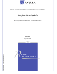
www.hurray.isep.ipp.pt
Technical Report
On the Hardware and Software
Architecture of the Robuter Mobile
Platform: a Hands-On Approach
Emmanuel Lomba
Mário Alves
TR-051103
Version: 1.0
Date: 29 November 2005
Technical Report #051103
On the Hardware and Software Architecture of the Robuter
Mobile Platform: A Hands-On Approach
On the Hardware and Software Architecture of the Robuter
Mobile Platform: A Hands-On Approach
Emmanuel LOMBA, Mário ALVES
IPP-HURRAY!
Polytechnic Institute of Porto (ISEP-IPP)
Rua Dr. António Bernardino de Almeida, 431
4200-072 Porto
Portugal
Email: {ecl,mjf}@isep.ipp.pt
Webpage: http://www.isep.ipp.pt
Abstract
The Robuter is a robotic mobile platform that is located in the “Hands-On” Laboratory of the IPP-Hurray!
Research Group, at the School of Engineering of the Polytechnic Institute of Porto. Recently, the Robuter
was subject of an upgrading process addressing two essential areas: the Hardware Architecture and the
Software Architecture. This upgrade in process was triggered due to technical problems on-board of the
robot and also to the fact that the hardware/software architecture has become obsolete.
This Technical Report overviews the most important aspects of the new Hardware and Software
Architectures of the Robuter. This document also presents a first approach on the first steps towards the use
of the Robuter platform, and provides some hints on future work that may be carried out using this mobile
platform.
Document history
Version
Content
By
Date
0.1
First draft.
ECL
18/10/2005
1.0
First release
ECL, MJF
29/11/2005
© IPP Hurray! Research Group
www.hurray.isep.ipp.pt
Technical Report #051103
On the Hardware and Software Architecture of the Robuter
Mobile Platform: A Hands-On Approach
Table of contents
1 Introduction..................................................................................................................................................................... 3
2 Robuter generalities........................................................................................................................................................ 3
2.1 General description..................................................................................................................................................... 3
2.2 General precautions.................................................................................................................................................... 5
3 Physical Architecture of the Robuter............................................................................................................................ 6
3.1 Main building blocks.................................................................................................................................................. 6
3.2 The RSMPC555 control board................................................................................................................................... 7
3.3 The embedded PC....................................................................................................................................................... 7
3.4 The sensors................................................................................................................................................................. 8
3.5 The actuators...............................................................................................................................................................8
4 Software Architecture..................................................................................................................................................... 9
4.1 Operative System........................................................................................................................................................ 9
4.2 Development tool....................................................................................................................................................... 9
4.3 SynDEx example design........................................................................................................................................... 10
5 Getting started guide..................................................................................................................................................... 12
5.1 Starting and shutting down....................................................................................................................................... 12
5.2 Joystick control......................................................................................................................................................... 12
5.3 Software control – commands.................................................................................................................................. 13
6 Conclusion, future works.............................................................................................................................................. 14
7 References.......................................................................................................................................................................14
© IPP Hurray! Research Group
www.hurray.isep.ipp.pt
2
Technical Report #051103
On the Hardware and Software Architecture of the Robuter
Mobile Platform: A Hands-On Approach
1 Introduction
The Robuter is a robotic mobile platform that is located in the “Hands-On” Laboratory of the IPP-Hurray!
Research Group, at the School of Engineering of the Polytechnic Institute of Porto. Recently, the Robuter
was subject of an upgrading process addressing two essential areas: the Hardware Architecture and the
Software Architecture. This upgrade in process was triggered due to technical problems on-board of the
robot and also to the fact that the hardware/software architecture has become obsolete.
In order to enable a practical use of the Robuter mobile platform (referred as „Robuter“ in the remain of this
Technical Report), a sort of “getting started guide“ is mandatory. Thus, this document provides the most
relevant technical information the Robuter hardware and software achitecture
This Technical Report starts by presenting some general characterisitcs of the Robuter, in Section 2. Then,
Section 3 introduces the physical (hardware) architecture of the robot. The main hardware components are
explained in a „what“ and in a „what for“ manners. Some relevant technical characteristics are also included,
in order to allow the expanding of the functionality of the current Robuter.
Section 4 describes the logical (software) architecture of the Robuter, namely how the control software is
organized and how the user can actually use the robot. Also, an application development example is
presented, based on the manufacturer's (Robosoft) documentation.
Section 5 gives a first practical approach to the Robuter with a simple demonstration on how to put the whole
system running and how to control it via a Joystick or via commands sent throught a serial connection.
Finally, some sugestions on future work are presented on Section 6.
Further information about the Robuter is actually available via Internet at the following address:
http://212.208.189.50/PROJECTS/ROBUTER_RECT/Project/User_Information.html
However, since the above address is not a property of the IPP-Hurray! Research Group, a dedicated site for
the Hurray's Robuter is under development, and will be hosted by the IPP-Hurray Research Group
webserver.
2 Robuter generalities
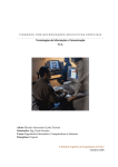
2.1 General description
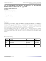
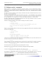
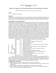
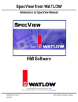
The Robuter (Figure 1) is a rectangular non-holonomic robotic mobile platform, developed by the french
company Robosoft. The locomotion of this robot is performed via the control of two independent DC motors
coupled to each drive wheel. Two additional caster wheels provide the necessary base on the floor.
The Robuter is controlled by an MPC555 micro-controller, allowing manual driving with a Joystick or
autonomous motion controlled by a Single Board Computer that is located inside the robot. Besides this
facility, it is also possible to remotely control that robot via a wireless radio link.
© IPP Hurray! Research Group
www.hurray.isep.ipp.pt
3
Technical Report #051103
On the Hardware and Software Architecture of the Robuter
Mobile Platform: A Hands-On Approach
Length:
102.5 cm
Width:
68.0 cm
Height:
44.0 cm
Weight:
150 kg
Payload:
120 kg
Max. speed:
1.0 m/s
Figure 1 – Robuter Mobile Platform
Basically, the Robuter is equiped with the following items:
2 x 300W DC motors, with gear boxes and brakes;
2 x incremental encoders;
2 x servo-amplifiers;
2 x axes interface between motors and boards;
4 x short range ultrasonic sonars (MIC130);
2 x medium range ultrasonic sonars (MIC340);
1 x RSMPC555 control board dedicated to multi-axis control;
1 x Pentium4 class embedded computer;
1 x Joystick 2-axis for manual operation with security button.
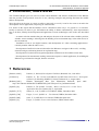
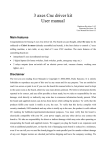
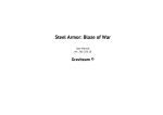
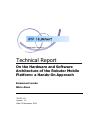
The onboard computer features the Linux Operating System implementing Real-Time operation using the
Real-Time Application Interface1 (RTAI). Figure 2, ilustrates some of the main components of the Robuter.
Figure 2 – Main components of the Robuter
1
http://www.rtai.org
© IPP Hurray! Research Group
www.hurray.isep.ipp.pt
4
Technical Report #051103
On the Hardware and Software Architecture of the Robuter
Mobile Platform: A Hands-On Approach
Besides a medium range ultrasonic sonar (MIC340) and an emergency STOP button, the rear panel features a
battery level indicator and a chronograph (hour counting). Also, this same panel presents the socket for the
control joystick plug.
The Robuter is electrically powered by four 12 V DC sealed lead batteries, serially connected, thus offering a
DC output of 48V. However, some components (sonars) are supplied with 24 V and other components have
dedicated DC/DC converters in order to adjust the power supply to the apropriate levels.
The socket for battery charge is located below the front panel; this panel, as for the rear one, can be lift
enabling the access to the internal parts of the robot may be possible.
2.2 General precautions
The development of any software application can take place in the Robuter's computer via a remote session
through Ethernet connection. In order to save battery life, this development phase should be carried out with
the battery charger plugged into the appropriate socket (below the front panel).
However, when running practical tests that involve motion of the robot, the battery charger plug should be
previously removed from the Robuter, in order to protect the charger from any current overload, as for the
cable itself that may not be long enough. This precaution should be taken into consideration even when the
Robuter is suspended on blocks2.
2
Refer to the “Robuter rectangular base User Information”, for information on how to put the Robuter on blocks.
© IPP Hurray! Research Group
www.hurray.isep.ipp.pt
5
Technical Report #051103
On the Hardware and Software Architecture of the Robuter
Mobile Platform: A Hands-On Approach
3 Physical Architecture of the Robuter
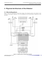
3.1 Main building blocks
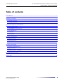
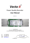
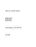
Figure 3 shows the main physical system block diagram. This diagram provides some intuition on the
location of each hardware component. A list of all capabilities for the current Robuter configuration is then
presented.
Figure 3 – Robuter physical system block diagram
© IPP Hurray! Research Group
www.hurray.isep.ipp.pt
6
Technical Report #051103
On the Hardware and Software Architecture of the Robuter
Mobile Platform: A Hands-On Approach
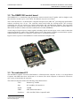
3.2 The RSMPC555 control board
The RSMPC555 is a stand-alone high performance motion control board. Together with its daughter card,
this controller can drive up to 4 axis robots. The Robuter only uses two of these.
This control board uses a 32-bit PowerPC compliant microprocessor (MPC5553) providing high performance
without sacrificing ease of use. The controller main board holds the microprocessor, the necessary
components for one axis control, user isolated input/output and communication channels. The piggy-back
style daughter card allows the extention from one axis up to four axis. The PC104 like connector allows to
add custom modules for future extensions (additional I/O, RAM, EEPROM).
A wide range of logical input or output signals, including optical encoder inputs can be used for both data
acquisition and device control. The available outputs can be either analog or PWM, to control linear or pulsewidth-modulation amplifiers, or digital to control relays or visualization systems.
Figure 4 shows a picture of the RSMPC555 control board and its daughter card.
Figure 4 RSMPC555 control board and Daughter card
3.3 The embedded PC
The embedded computer on board of the Robuter is a Pentium4 class computer. In fact, it is a Single Board
Computer with PSB form factor (185.01mm x 121.41mm). The whole computer is allocated in a shoe-box
style casing, located under the top panel.
This onboard computer features the following main characteristics:
- CPU:
Pentium4 @ 2.4GHz
- Bus:
PCI (33MHz), PC/104-PLUS
- RAM:
512MB
- HDD:
4GB, Hitachi Microdrive
- Interfaces:
ATA/100 IDE, FDD, CompactFLASH
3
http://www.freescale.com
© IPP Hurray! Research Group
www.hurray.isep.ipp.pt
7
Technical Report #051103
- Ports:
On the Hardware and Software Architecture of the Robuter
Mobile Platform: A Hands-On Approach
Ethernet IEEE802.3u 10BASE-T/100BASE-TX,
2 x USB 2.0, IrDA, LPT (EPP/ECP/SPP modes),
COM1 (RS-232), COM2 (RS-232, RS-422, RS-485),
4-bits Digital I/O, 2x CAN ports
- Peripherals:
Keyboard + Mouse PS/2 connector
- Video:
VGA controller AGP2.0 4x 3D graphic engine 8MBram (2048x1536x16)
- other features: Integrated real-time clock, intel 845GV chipset.
Although, this computer is a main hardware part in the robot, it has (so far) a minimal role in the control of
the Robuter. Currently, this computer is used to load the executable control application into the control board
via CAN bus and to communicate with it via serial RS232 link.
The computer can however be used to develop and run higher level applications and to communicate via
different types of link (other than CAN or RS232, provided on the control board), e.g., WiFi. Additionaly the
fact that the computer is mounted inside the robot enables a lot of expansion and enhancement opportunities.
3.4 The sensors
Actually, the Robuter is equiped with two kinds of sensors. The first kind is related to the emergency STOP
button, this one has top priority. This button stops the robot as it resets the control board. This button can
only be operated by human action. Also, the joystick belongs to this first category of sensors, as it also
requires human action.
The other sensor group includes all sensors that are related to the robot navigation. In this group, the Robuter
has ranging, and dead reckoning sensors.
The Robuter's ranging sensors are of two types, disposed as showed previously on this document, in Figure
2. Resuming, there is one medium range sensor on each front and back panels, and two short range sensors
on each side of the robot.
The front and rear panels sensors are of type Microsonic MIC3404 with a detection range between 35cm and
5 meters, thus having a blind zone up to 35cm.
The side sensors are of type Microsonic MIC1305, with a detection range between 20cm and 2 meters,
having a blind zone up to 20cm.
These sensors are ultrasonic ranging sonars with an analog signal output that is a function of the distance
between the top of the sensor and the first detected obstacle. Each sensor is connected to a separate analog
input of the RSMPC555 board.
The dead reckoning sensors are quadrature incremental encoders mounted on each drive motor axis. These
sensors are connected to the appropriate digital inputs of the control board. These sensors are used for
calculating the robot's position and for wheel velocity measurement.
Other sensors can be added to the Robuter, since its control board has several available analog and digital
inputs. Also, intelligent sensor modules can be added to the robot, as it provides several communication
interfaces such as RS232, USB, CAN and Ethernet.
3.5 The actuators
The only actuators included in the Robuter are the two drive motors mounted to each main drive wheel and
the electro-mechanical brakes. However, the Robuter's control board allows the control of two other axis
actuators, and several ON/OFF type ones (that can be plugged into its digital outputs).
4
http://www.microsonic.de/englisch/content_produkte/mic_plus/content_mic_plus_technisch_darstellung4_3.htm
5
http://www.microsonic.de/englisch/content_produkte/mic_plus/content_mic_plus_technisch_darstellung3_3.htm
© IPP Hurray! Research Group
www.hurray.isep.ipp.pt
8
Technical Report #051103
On the Hardware and Software Architecture of the Robuter
Mobile Platform: A Hands-On Approach
4 Software Architecture
4.1 Operative System
Robuter's embedded PC runs Linux RedHat 9.0 Operating System. This operativing system has the
avantages of being royalty free, open sourced, licensed under the GPL – General Public License, being very
well documented and featuring all necessary tools for development onboard of the Robuter itself (or
remotely via Ethernet).
Real-Time requirements can be fulfilled by loading into the Linux kernel some modules that provide realtime extentions and capabilities. These modules are from the RTAI6 – Real-Time Application Interface
project, from the Department of Aerospace Engineering of Politecnico di Milano (DIAPM).
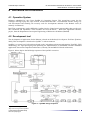
4.2 Development tool
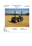
The development of applications for the Robuter is based on the Robosoft Development Toolchain [Pomiers,
2004]. This development is based on the SynDEx7 CAD environment.
SynDEx is a system level CAD software based on the "Algorithm Architecture Adequation" [SynDEx_UM]
methodology, for rapid prototyping and optimizing the implementation of distributed real-time embedded
applications onto multi-component architectures (currently x86 and MPC555 based architecture).
Figure 4, below, depicts the full design sequence of the SynDEx executives.
Figure 4 – SynDEX design sequence
6
http://www.rtai.org
7
http://www-rocq.inria.fr/syndex/
© IPP Hurray! Research Group
www.hurray.isep.ipp.pt
9
Technical Report #051103
On the Hardware and Software Architecture of the Robuter
Mobile Platform: A Hands-On Approach
SynDEx design methodology is based on some GNU development utilities (macroprocessor, compiler, etc)
to produce binaries. In the current case, the above sequence generates the PowerPC ELF 32-bit executable
applications for the MPC555 and the kernel modules for the PC (running RTAI\Linux).
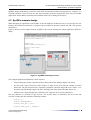
4.3 SynDEx example design
When designing an application with SynDEx CAD, the hardware architecture has to be specified. For the
Robuter, the hardware architecture is composed by one MPC555 operator (named P0) and a PC operator
(named PC).
Figure 5 shows a screen capture from the SynDEx CAD session featuring the sample application [Pomiers,
2004].
Figure 5 – SynDEX CAD design session
The example application implements a short sequence:
•
read an analog port on the control board (P0), that performs the analog to digital convertion;
•
use the result of the conversion (32-bit integer) as input for the func function running in control
board (P0). The func function calls a separately compiled C function and produces two values: a 32bit integer (passed through output 'o0') and a floating point value (passed through output 'o1');
•
send these two values (through the CAN bus) to the computer (PC), for being displayed.
The func function is a function of type myFunc. The myFunc macro is defined by the user in the file
'test.m4x'. Editing this file returns the following contents:
define(-1)
define(‘NOTRACEDEF’)
define(‘ECP_IRQ’,‘0x5’)
define(‘CAN_speed_’,800Kbps)
© IPP Hurray! Research Group
www.hurray.isep.ipp.pt
10
Technical Report #051103
On the Hardware and Software Architecture of the Robuter
Mobile Platform: A Hands-On Approach
define(‘loop_period’,‘10000000’)
# Robosoft MPC555 boards Serial Number (used by the download process)
define(‘P0_CANID_’,0x4000)
# PP: Fix IT timer period to 156/15625=10ms (refer to 555.m4x comments).
dnl define(‘PITCOUNTER’, 1562)
# -------------# myFunc()
#
define(‘myFunc’, ‘ifelse(dnl
MGC,‘LOOP’,‘Ccall_(void, ‘myCall’, int $1, int *$2, float *$3)’)’)
# display()
#
define(‘display’, ‘ifelse(MGC,‘LOOP’,‘dnl
{
int f = 0;
f = (int)(*$1 + *$2);
rt_printk("Sum of input values is %5d.\n", f);
}’)’)
divert‘’dnl
The user macro myFunc is defined as a call to the myCall function [555macros]. The myCall function is
declared in the local file 'myLib.c'. This function is scripted as follows:
#include "fdlibm.h"
void myCall (int in, int *iout, float *fout)
{
double f = 0.75;
*iout = (int)(100 * sin(f));
*fout = (float)(sin(in / 100.));
}
The next step is to add the appropriate makefile rules to the local 'GNUmakefile' and 'User.mk', in order to
automatically launch 'muLib.c' compilation.‘myLib.c’ should be compiled to produce an object file named
‘myLib.555’. Hence, called functions will be copied from ‘myLib.555’ and included into P0 operator object
file. At final compilation step, the composed P0 operator object file will be linked to produce the PowerPC
ELF 32-bit executable binary.
To do so, it is necessary to declare the object file ‘myLib.555’ as a valid library for the P0 operator. This is
done by setting the following variable into the local ‘GNUmakefile’:
P0.libs = myLib.555
Then, the makefile rule needed for producing ‘myLib.555’ has to be inserted. This is done by adding the
following line to the local ‘User.mk’:
myLib.555 : myLib.c
In fact, this rule only sets a dependency between ‘myLib.555’ and ‘myLib.c’. This means, that for compiling
‘myLib.c’ an implicit rule will be applied. This implicit rule corresponds to the one already defined by the
‘mpc555.m4m’ SynDEx kernel macros. Any additional specific need for compilation should be added like
follows:
© IPP Hurray! Research Group
www.hurray.isep.ipp.pt
11
Technical Report #051103
On the Hardware and Software Architecture of the Robuter
Mobile Platform: A Hands-On Approach
myLib.555 : myLib.c
../../crossgcc/bin/ppc-elf32-gcc -o myLib.555 -mcpu=powerpc\
-mhard-float -I../../crossgcc/fdlibm -O2 -c myLib.c
The application can be launched by executing the “make” command from the command prompt line.
'myLib.c' will be automatically compiled before producing 'P0'.
5 Getting started guide
5.1 Starting and shutting down
There are two ways of getting the Robuter started: locally or remotely. Locally, i.e., on the Robuter itself. A
monitor has to be plugged in the appropriate VGA socket, on the on-board embedded computer. In this case,
a keyboard and a mouse have also to be plugged (using a PS/2 splitter connector).
Nevertheless, as plugging some extra hardware on the Robuter is not a practical solution, a better solution
arises: plugging only a network cable on the RJ45 ethernet network plug. Note: even this solution (which
involves physical plug and unplug) should be substituted by a wireless radio link connection.Thus, once the
Robuter is turned on, it will be almost ready to go (just have to launch the application).
Whatever is the connection with the robot, via extra hardware or via (WiFi?) Ethernet connection, once the
Robuter is turned on and the Linux login prompt appears, login and password must be provided:
login: guest
password: guest0
As the Robuter can be seen as a “moving computer”, once it is not needed anymore, it should be turned off.
A normal Linux procedure has to be executed, i.e. shutting down the software platform, inserting the
following command on the command prompt:
> shutdown -h now
If no monitor is plugged on the Robuter, there is no information on when the computer system is off. So,
only after a while, the Robuter master switch can be turned off (e.g., 1 minute, based on practical tests with
local monitor).
5.2 Joystick control
For joystick control, the example application pre-installed by Robosoft can be used. To do so, the following
procedure has to be carried out.
1. Go to the application directory:
> cd syndex/current/last/appsv6/4190_RobuTERRect_Porto_V18
2. Push and release the emergency STOP button on the rear panel of the robot. This action resets the
control board. Now the PC is ready to download the application to the control board.
3. Compile, download and start the application:
> make
The platform is now ready to be operated by a joystick. Note that commands issued from the joystick are
only executed if the joystick button is pressed.
To terminate this application:
> make stop
© IPP Hurray! Research Group
www.hurray.isep.ipp.pt
12
Technical Report #051103
On the Hardware and Software Architecture of the Robuter
Mobile Platform: A Hands-On Approach
Then turning off the Robuter is possible, after a proper Linux machine shut down procedure, as stated earlier.
5.3 Software control – commands
When the Robuter is controlled by an application (software control), it can be considered that it behaves
autonomously, or not, depending on the type of application. If the robot does not need any specific external
command to navigate from one point to another (except, for the “go!” command), then he behaves
autonomously.
We address next how the Robuter can be remotely controlled, where direct command instructions are sent to
the robot via serial communication.
This type of communication can be achieved on board of the robot; i.e., the embedded PC sends commands
to the running application; this could be interprocess communication between a navigation application and
the control application. Or, an application on a remote host sending commands via a wireless media.
In order to control the robot via command instructions, the same steps presented in section 5.1 must be
executed except for the last one (shutting down).
Therefore, assuming the Robuter Linux machine is running in text mode, we should:
> login: guest
> password: guest0
> cd syndex/current/last/appsv6/4190_RobuTERRect_Porto_V18
(push and release the emergency STOP button)
> make
Then, in a second terminal (CTRL+ALT+F2), the minicom application will be used to communicate with the
running control application.
> login: guest
> password: guest0
> minicom8
(in the minicom window)
> CTRL+A and SHITF+A (activates line feed)
> CTRL+A and SHIFT+E (activates the Echo)
After this minicom terminal startup and configuration, the first command to be sent to the control level is to
switch the control to the serial line (code 1 and mode 1):
> R 1 1
Then, the Robuter will accept commands from the serial line of the control board. For example, to perform a
translation of 4000 enconder ticks (753mm), at a speed of 50 encoder ticks per 10ms, we should enter:
> R 400 46000 50
The wheels perform a turn implementing a trapezoidal profile of velocity.
Returning to the joystick control mode is achieved by sending the following command
> R 1 0
As usual, to terminate this real-time application, after exiting minicom:
> make stop (on the first Linux command prompt – CTRL+ALT+F1)
This method of communicating with the robot not only allows to send commands, but also to “ask” for
systems state variables (e.g. > R 7 2 returns the distances measured by the ultrasonic sensors).
A full list of control commands is available in the Robuter technical documentation [Robuter@web].
8
Minicom settings are: 115200 8N2
© IPP Hurray! Research Group
www.hurray.isep.ipp.pt
13
Technical Report #051103
On the Hardware and Software Architecture of the Robuter
Mobile Platform: A Hands-On Approach
6 Conclusion, future works
This Technical Report gives an overview of the current hardware and software architecture of the Robuter
and also provides some practical issues for its use, showing examples and pointing directions that enable
further development.
Since the robot can be seen as a mean to achieve some task (as a tool), it can be also seen as an end in the
development of new applications, improving its characteristics.
It is shown in this report that the Robuter can be controlled in three ways: via joystick or via software,
locally or remotely. In order to give the Robuter the ability to behave autonomously, some improvements
have to be done, namely the development and application of some technologies; such as the ones described
next:
- A remote real-time monitor that gets and analyzes the state of the relevant robot variables: position,
attitude, sensors readings. Allowing also the building of an environment map, as the robot moves in
the environment;
- Installation of one or two digital cameras, and development of a video streaming application to
remotely monitor what the robot “sees”;
- Development of artificial vision tools that allow the Robuter to navigate in the world, avoiding
obstacles and geo-referencing them in an exploration map;
- Development of vision-based navigation algorithms with fusion of all available sensor data;
- Development of an autonomous docking station and respective control application, for enabling the
Robuter to get its batteries charged, between missions.
7 References
[Pomiers, 2004]
Pomiers, P., Robosoft Development Toolchain, Robosoft S.A., June 2004.
[555macros]
Pomiers, P., The 555,m4x and RSB.m4x SynDEx Macro-Executives: Description
of Macros for Handling RSMPC555 boards, Robosoft S.A., August 2004.
[Robuter@web]
Robuter Rectangular Base User Information, Robosoft,
http://212.208.189.50/PROJECTS/ROBUTER_RECT/Project/User_Information.html
April
[SynDEx_IO]
Pomiers, P., The SynDEx “linuxIO_” Macro: An Easy C/C++ Linux User's
Application Interface, Robosoft S.A., April 2004.
[SynDEx_TUT]
Santos, N., et al., SynDEx v6 TUTORIAL, INRIA, December 2003.
[SynDEx_UM]
Forget, J., et al., SynDEx v6 – User Manual, INRIA, December 2003.
[SynDEx_RM]
Sorel, Y., SynDEx Reference Manual, INRIA Rocquencourt.
[SynDEx_Gr]
Forget, J., SynDEx version 6.6.8 Grammar, INRIA, March 2004.
© IPP Hurray! Research Group
www.hurray.isep.ipp.pt
2005
14