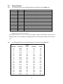
1
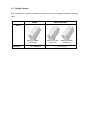
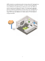
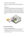
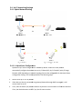
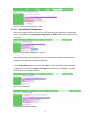
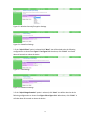
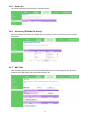
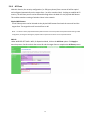
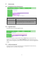
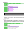
AX821 ConnectedLife Wi-Fi
Fi Booster
User's Manual
Table of Content
1. IMPORTANT INFORMATION ........................................................................................... 1
1.1.
IMPORTANT SAFETY NOTES ........................................................................................... 1
2. INTRODUCTION ............................................................................................................... 2
2.1.
PACKAGE CONTENT ...................................................................................................... 3
2.2.
PRODUCT OVERVIEW .................................................................................................... 4
2.3.
BUTTONS AND LEDS .................................................................................................... 4
3. HARDWARE INSTALLATION .......................................................................................... 5
3.1.
APPLICATION 1 – WI-FI RANGE EXTENDER ..................................................................... 5
3.2.
APPLICATION 2 – FULL HY-FI NETWORKING ................................................................... 7
4. ENCRYPTED PLC NETWORK......................................................................................... 7
4.1.
CREATE AN ENCRYPTED PLC NETWORK GROUP ............................................................ 7
4.2.
REMOVE DEVICE FROM AN EXISTING NETWORK GROUP .................................................. 9
4.3.
CREATE ADDITIONAL ENCRYPTED NETWORK .................................................................. 9
5. ADVANCED WI-FI SETTINGS VIA WEB BROWSER .................................................... 10
5.1.
GETTING STARTED ..................................................................................................... 10
5.2.
LOG IN TO THE SETTING PAGE ..................................................................................... 12
5.3.
HOME ........................................................................................................................ 13
FOR CONFIGURATION IN THE HOME, TAKE THE FOLLOWING STEPS: ............................................ 13
5.3.1.
SELECT LANGUAGE ................................................................................................ 13
5.3.2.
SETUP WIZARD ....................................................................................................... 13
5.3.3.
OPERATION MODE .................................................................................................. 14
5.4.
5.4.1.
HY-FI NETWORKING SETTINGS .................................................................................... 16
HYBRID NETWORK SETTING ..................................................................................... 16
5.4.1.1. HYBRID AUTO CONFIGURATION ................................................................................. 16
5.4.1.2 HYBRID MANUAL CONFIGURATION ........................................................................... 17
5.4.2
POWERLINE SETTINGS ............................................................................................ 19
2
5.4.3
5.5
5.5.1
5.6
HY-FI AUTO-CONFIGURATION .................................................................................. 19
INTERNET SETTINGS ................................................................................................... 20
LAN (LOCAL AREA NETWORK SETTINGS) ................................................................ 20
WIRELESS SETTINGS .................................................................................................. 21
5.6.1
BASIC (BASIC WIRELESS SETTINGS) ........................................................................ 21
5.6.2
ADVANCED (ADVANCE WIRELESS SETTINGS) ............................................................ 22
5.6.3
SECURITY (WIRELESS SECURITY/ENCRYPTION SETTINGS) ......................................... 23
SECURITY MODE: CHOOSE ONE FROM THE OPTIONS. ............................................................... 23
5.6.4
WPS (WI-FI PROTECTED SETUP) ............................................................................ 26
5.6.5
STATION LIST .......................................................................................................... 28
5.6.6
SITE SURVEY (AP MODE SITE SURVEY) ................................................................... 28
5.6.7
MAC FILTER .......................................................................................................... 28
5.6.8
AP CLONE ............................................................................................................. 29
5.7
ADMINISTRATION ........................................................................................................ 30
5.7.1
MANAGEMENT (SYSTEM MANAGEMENT) ................................................................... 30
5.7.2
UPGRADE FIRMWARE ............................................................................................... 30
5.7.3
SETTINGS MANAGEMENT ......................................................................................... 30
5.7.4
STATUS .................................................................................................................. 31
5.7.5
STATISTICS ............................................................................................................. 32
5.7.6
SYSTEM LOG .......................................................................................................... 32
5.8
CHANNEL NUMBER ..................................................................................................... 33
6 ENHANCE PLC PERFORMANCE ................................................................................. 35
7 SPECIFICATIONS .......................................................................................................... 37
3
1. Important Information
1.1. Important Safety Notes
This device is intended for connection to the AC power line. For installation instructions, refer to
the Installation section.
The following precautions should be taken when using this product:
•
•
Please read all instructions before installing and operating this product.
Please keep all instructions for later reference.
•
Please follow all warnings and instructions marked on the product.
•
For safety reasons, this device should not be installed in any electric socket when being
powered on to prevent the venting holes from facing the floor.
•
•
•
•
•
Unplug the Powerline device from the wall outlet before cleaning.
Use a dry cloth for cleaning. do not use liquid cleaners or aerosol cleaners.
Do not operates this device near water.
This device should never be placed near or over a radiator, or heat register.
This device relies on the building’s electrical installation for short-circuit (over current)
protection.
•
•
•
Do not allow anything to rest on the device interconnect plug.
Do not place this device in a location where people may walk on the cords.
Because this device sends data over the power line, it is recommended that you plug it directly
into a power outlet.
•
Do not plug the device into a UPS or power strip with surge protection. (The device has its
own power filter for protection against surges.)
•
Only a qualified technician should service this device. Opening or removing covers may result
in exposure to dangerous voltage points.
•
Unplug the device from the wall outlet and refer the device to qualified service personnel if
the following occurs:
-
If the interconnect cords are damaged or frayed.
If liquid has been spilled onto the device.
If the device has been exposed to rain or water.
If the device does not operate normally when the operating instructions are followed.
If the device exhibits a distinct change in performance.
1
2. Introduction
This user manual describes the AX821: ConnectedLife Wi-Fi Booster device.
The AX821 ConnectedLife Wi-Fi Booster is a high-performance router and/or Wi-Fi range extender
and booster that can be plugged into any outlet in the home to create a robust Wi-Fi network. With
the increasing number of mobile, tablet, and Wi-Fi enabled Smart TVs and Blue-Ray player devices
that stream video in the home, the demand for speedy Wi-Fi is growing. The AX821 is designed to
be a flexible, easy-to-install device that can deliver high-performance Wi-Fi connectivity anywhere
in the home.
Unlike traditional Wi-Fi repeaters or boosters, the AX821 combines the performance of HomePlug
Power Line Communications (PLC) and Dual-Band 802.11abgn Wi-Fi to guarantee robust, whole
home Wi-Fi coverage. By implementing HomePlug PLC technology, the AX821 performance is not
affected by the construction materials used in the home (i.e. brick, concrete, metallic framing, etc),
as it uses the homes electrical wiring as a networking conduit, bringing high-speed, wireless
Internet connectivity to locations where simple Wi-Fi solutions cannot.
The AX821 ConnectedLife Wi-Fi Booster is also designed to prevent the loss of outlet access, which
simplifies the installation for the consumer. Additionally, the pass-through plug uses advanced noise
filtering to ensure that the device’s performance is not impacted when even the noisiest of devices
are plugged into the AX821's replicated power outlet.
Through the implementation of SmartLink™ technology, the AX821 enhances performance and
home coverage by leveraging all three electrical wires—line, neutral and ground. This new offering
increases overall network performance by up to 50% when compared to HomePlug solutions that
only utilize the line and neutral wires. The result is a more robust Internet connection that can be
accessed anywhere in the home.
The AX821 is compliant with HomePlug AV Specification standard and is equipped with 128-bit AES
encryption to keep data secure.
2
2.1. Package Content
Before starting the installation of the d
device,, please make sure the package contains the following
items:
AX821
AX821-BX
BX (Bundle)
Device
Accessories
AX821 ConnectedLife
AX821 ConnectedLife
AX821 ConnectedLife
Wi-Fi
Fi Booster
Wi-Fi Booster
Wi-Fi
Fi Booster
RJ-45
45 Cable x 1
RJ-45
45 Cable x 2
3
2.2. Product Overview
AX821 ConnectedLife Wi-Fi
Fi Booster
AC Pass-through
through Socket
A
B
C
D
E
F
G
H
Ethernet Port
2.3. Buttons and LEDs
Image Label
A
B
LED
ON:: Power on and ready.
Blinking
Blinking: PLC group pairing.
OFF:: Power off.
ON:: PLC connection detected.
Blinking
Blinking:
1. Fast
Fast: Powerline data rate > 60Mbps
2. Normal
Normal:60Mbps > Powerline data rate > 10Mbps
3. Slow
Slow: 10Mbps > Powerline data rate
OFF:: No PLC connection detected.
(They are too far to communicate or it is alone in its logical network).
Steady Green
Green: Wi-Fi network with security protection.
Flash Green
Green: Wi-Fi
Fi network traffic in transaction with security protection.
Steady Red
Red: Wi-Fi network without security protection.
C
Flash Red
Red: Wi-Fi
Fi network traffic in transaction without security protection.
Blinking Green (0.5 sec ON / 0.5 sec OFF): WPS negotiation.
OFF:Wi
Wi-Fi disabled.
4
ON: Ethernet connection detected.
Blinking
Blinking: Network traffic in transaction.
D
OFF: No Ethernet connection detected.
Buttons
E
Power Button
Push to power on/off the device.
AP Clone by default. The function follows Operation Mode setting in WPS
F
configuration.
Press 10 seconds
seconds:
Randomly generate
g
a new PLC network group name.
Press 1 to 3 seconds:
G
Start paring with the other PLC device. Paring procedure keeps for 2 minutes or
ends automatically when they are paired. It can be stopped manually by pressing
the button for 1 to 3 seconds again.
H
Reset
Press 1 second
second: Reset to factory default setting.
Button
Press the button when the device is powered (not in standby mode)
3. Hardware Installation
The AX821 ConnectedLife Wi-Fi
Fi Booster intelligently auto-configures itself based on the role it
plays in the home network, with little
little to no consumer intervention. Specifically, the
t device can
automatically determine if it needs to act as the home router itself, or as a Wi-Fi
Fi range
extender to boost the Wi-Fi
Fi signal of the existing home router.
In many of today's connected homes, Wi-Fi
Wi Fi routers are limited to operating in the 2.4GHz
2.4
band,
which tends to be over-crowded
crowded with access points, ul
ultimately
timately limiting performance. The
AX821, when connected to this router over a simple Ethernet connection, can operate in the
5GHz band, creating a dual-band,
band, dual concurrent Wi-Fi
Wi network which
h can deliver robust
streaming video quality to mobile and tablet devices.
The AX821 will dynamically determine its role in the connected home network.
Examples of these roles are provide below:
3.1. Application 1 – Wi-Fi Range Extender
Install the AX821-B bundle to extend the existing home routers Wi-Fi
Wi coverage.
Quick Installation:
In this example, an AX501 is connected to the existing home router, and the
5
AX821 is placed in a remote location within the home where Wi
Wi-Fi
Fi coverage from
the existing router is poor or non
non-existent. The AX821's EasyConnect feature
clones a WPS (Wi-Fi
Fi Protected Setup)-enabled
Setup)
home router's Wi-Fi
Fi SSID and
security credentials
als with the push of a button. This allows mobile and tablet
devices to seamlessly roam between the home rou
router's Wi-Fi
Fi and the AX821's
Wi-Fi without the need for manual intervention. If the home router does not
support WPS, then a web browser on a mobile, tablet, or PC can be used to
configure the AX821.
6
3.2. Application 2 – Full Hy
Hy-Fi Networking
The AX821, when combined with a second AX821 (i.e. AX821
AX821-BX
BX Bundle) will create the most
robust home networking solution in the industry due to the support of Qualcomm Hy-Fi
technology.
Quick Installation:
In this example, the first AX821 is connected to the existing home router, and the
second AX821 is placed in a remote location within the home where Wi-Fi
Wi
coverage from the existing router iis poor or non-existent. Thanks to the support
of Hy-Fi,
Fi, the two AX821 devices will auto-configure
auto configure themselves based on their
respective roles in the network. The supported configurations are Hy-Fi
Hy Router,
Hy-Fi Extender, or Hy-Fi
Fi Client
Client. The Hy-Fi
Fi software will automatically deter
determine
how the devices need to work with each other to create the most robust network
possible.
4. Encrypted PLC Network
4.1. Create an Encrypted PLC Network Group
The AX821 ConnectedLife Routers/Extenders are compliant with HomePlug AV specification.
Every ‘HomePlug AV’ compliant PLC device that has the same default network name,
“HomePlug AV”,
”, is capable of communicating with other “HomePlug AV” devices. This is the
so-called “Public Network”.
”. This allows two or more Powerline
P
ine devices under the same network
can communicate with one another.
7
If you have a pair of Powerline
owerline devices,
device , either one in the pair can be “device A” or “device B”. By
pressing the GROUP button for more than 10 seconds, it will generate a random network group
(different from HomePlug AV). Users can take the following two steps to change the public
network group to a private network group to protect their data while transmitting over the
powerline. Users also can create more
m
than one private network group by pressing GROUP
button directly without any software installation required.
*NOTE: Placing the devices side-by-side
side will be more convenient during the setting procedure. After the network
group is set, the devicess can be deployed anywhere in the home.
Step I: Clear Group Attribute
Clear the original network group of device B by pressing the GROUP button for more than 10
seconds until all LED lights simultaneously turn off and on one time. Now,, its network group
name has been
en changed to a random name. This means that this device is (1)
( ready to be
assigned another network name or (2) ready to be used as a seed device so other PLC devices
can join a private network group.
Step II: Join to Other Network Group
1. Presss GROUP button of device A for 2 to 3 seconds (make sure POWER LED starts
blinking).
2. Press GROUP button of device B for 2 to 3 seconds (make sure POWER LED starts
blinking).
Device B, which has cleared its group attribute
attribute, will join to the Device A, which
whi has not. This
step ensures that device A and B are both under the same encrypted network. An additional
device C can be added into device A’s logical network by following the same steps. The u
user is
able to assign as many Powerline
owerline devices into the logical network group as allotted in the
SPECIFICATION section.
*NOTE: It does not matter which device’s button is pressed first, but please press the second device’s GROUP
button within two minutes after pressing first device’s GROUP button. After 10 seconds, device will start
communicating with device A.
8
4.2. Remove Device from an Existing Network Group
If you would like to remove Powerline device from an existing network group, generate a new
group name (referring to Step I) to stop communication with an existing network group.
4.3. Create Additional Encrypted Network
If you want to create an additional private network for your power line devices that co-exist
with your existing Powerline private network group, please repeat Steps 1-2 to generate a new
private network group for selected Powerline devices.
NOTE: Users can press the RESET button to reset the network name back to its factory default.
9
5. Advanced Wi-Fi Settings via WEB Browser
5.1. Getting Started
To set up advanced Wi-Fi features such as an SSID or password, please connect to AX821 via
Ethernet or wireless connection, and log in to the setting page through a web browser.
Default username: root
Default password: root
Before logging in to the settings page, the PC or mobile device should be in the same subnet as
this device. To do so, please manually change the PC or mobile's IP address.
Go to "Network Connections" - "Local Area
Connection" "Connection Status" and choose the
Internet Protocol (TCP/IP) and click on
"Properties".
10
Enter IP address such as 192.168.1.XXX
(XXX can be set from 1-128) and click OK
Go to "Settings" - "Wi-Fi" - "Selected SSID" "Advanced settings", then click on "Static" to enter IP address
such as 192.168.1.XXX. (XXX can be set from 1-128) and
Subnet Mask 255.255.255.0
Go to "Settings" - "Wi-Fi" – Press and Hold "Selected SSID" to modify network - then
click on "Show advanced options".
Click "IP settings" to choose "Static" to enter
address such as 192.168.1.XXX.
(XXX can be set from 1-128)
11
5.2. Log in to the Setting Page
Step 1
Step2
Open the web browser and type in
IP address 192.168.1.2
(the IP of this device).
When you see the login window, enter
"root" in both the user name and
password fields.
Note: you can change user name and
Step 3
The AX821 setting page will be
displayed after a successful login. Then, you can
start configuring all necessary settings from
here.
Note: After completing all necessary configurations, DO NOT forget to change the PC or
mobile device's IP address back to your original setting.
12
5.3. Home
For configuration in the home, take the following steps:
5.3.1. Select Language
Currently, English is only the available option in the language setting.
5.3.2. Setup Wizard
The setup Wizard assists you in setting up the device with the minimum amount of required
settings. To do this, click “SETUP
SETUP WIZARD”
WIZARD on the left panel. Then, click the “Next” button. The
wizard will then guide you through the required settings.
:Set up account and password configuration for device login.
Step 1:
Step 2:
:Set up LAN interface.
Step 3:
mode, SSID, etc.
:The page is for basic wireless setting to set network mode
Step 4:
:Set up wireless security and encryption to prevent unauthorized access.
Step 5:
:Click “Finish”” button and the device will reboot to apply the changes.
13
5.3.3. Operation Mode
This device supports five operation modes for the IP network. Click to select one from the
following options and then click the “Apply” button.
AP Mode
The device acts as Wireless Access Point (AP) for wireless clients, and provides connections to
Ethernet and PLC.
Client Mode
This mode enables the establishment of connection to the other AP by using infrastructure
/Ad-hoc networking types. With bridge operation mode, you can directly connect the wired
Ethernet port to your PC and the device will become a wireless adapter.
WDS (Root AP)
The wireless radio device serves the other AP by providing a connection to a wired LAN (the
other AP must use the same chipset as this device).
WDS + AP Mode
This mode combines WDS mode with AP mode, allowing WDS connections and ensuring that
14
wireless clients can survey the device.
WDS Mode
WDS is used to create a network of APs that can be used as one single “virtual” AP. To do so, the
device forwards the packets to another AP with WDS functionality. When this mode is selected,
all wireless clients cannot survey or connect to the device. The device only allows the WDS
connection in WDS mode.
15
5.4. Hy-Fi
Fi Networking Settings
5.4.1. Hybrid Network Setting
5.4.1.1. Hybrid Auto Configuration
Qualcomm Hy-Fi Auto Configuration is enabled by default. Under this mode, devices
automatically configure themselves into aan Hy-Fi Router(HR), Hy-Fi
Fi Client(HC) or Hy-Fi
Hy Range
Extender (HRE) depending on network topology. Please refer to Figure 5-1 for this
th Hybrid Auto
Configuration setting. This can be explained
explaine in the following steps:
1.
2.
3.
Device starts up as a HC by default.
If the device is directly connected to a gateway (detected through DHCP messages), it will
convert itself to an HR.
If not,, then the device (HC) detects whether any devices are connected to its Ethernet interface.
If not,, the device becomes a HRE. If yes, the HC status remains.
16
Figure 5-1: Hybrid Auto Configuration - Enable
5.4.1.2
Hybrid Manual Configuration
You can also assign the device as an HR, HC or HRE manually when Hybrid Auto Configuration
mode is disabled by setting Hybrid Auto Configuration to Disable. Please refer to Figure 5-2 for
the setting.
Figure 5-2: Hybrid Auto Configuration - Disable
After disabling Hybrid Auto Configuration, you can manually set the device to the options as
shown from the dropdown list shown in Figure 5-2.
1. If the Hybrid Router option is selected, click “Next”. You will be asked to do the following
configurations as shown from Figure 5-3 to Figure 5-6. Once done, click “Finish”. It will take
about 40 seconds to reboot the device.
Figure 5-3: LAN Settings
Figure 5-4: Basic Wireless Settings
17
Figure 5-5: Wireless Security/Encryption Settings
Figure 5-6: Powerline Settings
2. If the “Hybrid Client” option is selected click “Next”. You will be asked to do the following
configurations as shown from Figure 5-7 to Figure 5-8. Once done, click “Finish”. It will take
about 40 seconds to reboot the device.
Figure 5-7: LAN Settings
Figure 5-8: Powerline Settings
3. If the “Hybrid Range Extender” option is selected, click “Next”. You will be asked to do the
following configurations as shown from Figure 5-9 to Figure 5-11. When done, click “Finish”. It
will take about 40 seconds to reboot the device.
18
Figure 5-9: IEEE 1905.1 Security Settings
Figure 5-10: LAN Settings
Figure 5-11: Powerline Settings
5.4.2
Powerline Settings
Network Password: HomePlugAV.
You can specify a new value if you’d like your powerline network to be separate from other
powerline networks.
“Save” the configuration for it to take effect.
5.4.3
Hy-Fi Auto-Configuration
This feature, enabled by default, automatically conveys IEEE 802.11 parameters from a registrar
to an AP enrollee to set up the initial configuration or renew an existing configuration of an IEEE
802.11 interface. IEEE 1905.1 AP Auto-Configuration is used to automatically configures
multiple APs to share a single configuration (i.e. same SSID and Pass Phrase). This enables
19
seamless roaming of wireless clients in the network.
Hy-Fi Auto-Configuration functions as follows:
•
•
Devices start up as a HC.
HR, HRE, and HC all have the same firmware, but the one directly connected to
gateway (i.e. home router running a DHCP server) via its Ethernet will turn itself into
an HR, acting as the AP Auto-Configuration registrar.
•
HC detects whether any devices are connected to its Ethernet internet. If none, it
becomes an HRE (AP enabled, acting as the enrollee). Via web interface, the role of
being an HRE can also be manually configured.
5.5
5.5.1
•
When you plug in Hy-Fi enrollee AP devices (e.g. HRE or RE), security configuration (i.e.
SSID, pass phrase) from the HR in the same group will be copied and configured
automatically on the HRE or RE. This means security configuration on the HR (the
registrar) will be propagated to the other APs (the enrollee APs) in the network.
•
DHCP client is enabled by default on the device and the device automatically gets an IP
address.
Internet Settings
LAN (Local Area Network Settings)
LAN setup
Item
Description
IP Address
The Internet Protocol (IP) address.
Subnet mask
The number used to identify the IP subnet network.
Hybrid Auto-Configuration will run a DHCP client on all devices, which will override the manual IP
settings. If no DHCP server is found, the default 192.168.1.2 IP address will be used.
20
5.6
5.6.1
Wireless Settings
Basic (Basic Wireless Settings)
Wireless Network
Item
Description
Radio On/Off
Click to enable/disable wireless function.
Network Mode
Network Name (SSID)
Frequency (Channel)
The available options are 11b, 11g, 11g/n HT20, 11g/n HT40 PLUS (default), 11
g/n HT40 MINUS.
The SSID, which is also called ESSID, is a unique identifier that wireless
networking devices use in order to establish and maintain wireless connectivity.
A SSID can contain up to 32 alphanumeric characters.
Click the drop down box to select the radio channel. Select the unused channel
to prevent radio overlapping.
HT Physical Mode
Item
Description
Default: Mixed (Mixed, Green Field).
Mixed mode: In this mode the device transmits the packets with preamble
compatible legacy (802.11g), so that they can be decoded by legacy devices. The
Operating Mode
device receives and decodes both Mixed Mode packets and legacy packets.
Green Field mode: the device transmits HT packets without the legacy
compatible part. The device receives and decodes both Green Field and legacy
packets.
The 11n device inserts the Guard Interval into the signal. You can choose the
Short Guard Interval
interval between “Long” and “Short”. This option affects the Phy data rate of
radio. Please refer to the table below.
MCS
Modulation Coding Scheme. The available options are “Auto, 0, 1-7”. It changes
the modulation of this device and effects the maximum Phy data rate. We
recommend the “Auto” setting. For more details, please refer to the table below.
Aggregation MSDU
Multiple HT packets can be transmitted with single ACK reply packet. Enable it to
21
(A-MSDU)
apply this function and reduce the network congestion.
Auto Block ACK
Aggregation technique which prevents sending ACK in the communication to
increase the throughput. If this option is enabled, the device will activate this
function when transmitting massive data.
5.6.2
Advanced (Advance Wireless Settings)
Advanced Wireless
Item
Description
You can select the other options including “On” and “Off”. The B/G protection
BG Protection Mode
technology is CTS-To-Self, so it will try to reserve the throughput for 11g clients
from 11b clients connecting to the device as AP mode.
Beacons are the packets sent by the access point to synchronize the wireless
Beacon Interval
network. The beacon interval is the time interval between beacons by this unit in
AP or AP+WDS mode. The recommended default beacon interval is 100
milliseconds.
Data Beacon Rate (DTIM)
This is the Delivery Traffic Indication Map, used to alert the clients that multicast
and broadcast packets buffered at the AP will be transmitted immediately after the
transmission of this beacon frame. You can change the value from 1 to 255. The AP
will check the buffered data according to this value. For example, selecting “1”
means that the buffered data is checked at every beacon.
Short Preamble
Default: Disable. It is a performance parameter for 802.11 b/g mode and is not
supported by some of very early stage of 802.11b station cards. If there is no such
kind of stations associated to this AP, you can enable this function.
Tx Burst
The device will try to send a series of packages with single ACK reply from the
clients. Enable this function to apply.
Wi-Fi Multimedia
22
Item
Description
WMM Capable
Choose “Enable” to apply WMM function.
APSD Capable
Turn on this feature so this device can detect whether the connecting wireless
client device has turned on the power saving feature. If yes, this device will send
packets with power saving tags accordingly.
WMM Parameter
Click this button to edit the WMM parameter.
5.6.3
Security (Wireless Security/Encryption Settings)
Security Mode: Choose one from the options.
Wireless Security/Encryption Settings
Item
Description
Security Mode
Disable, OPEN, SHARED, WEPAUTO, WPA, WPA-PSK, WPA2, WPA2-PSK,
WPA/WPA2 PSK, WPA/WPA2, 802.1X.
Encryption Type: Options vary depending on the authentication mode. The corresponding
options are listed below:
Authentication
Encryption type
Key option
OPEN, SHARED, WEPAUTO
WEP
Default Key ID, WEP Keys 1/2/3/4
WPA/WPA2 PSK (Pre-Shared
TKIP, AES, TKIP/AES
Pass Phrase, Key Renewal Interval
TKIP, AES, TKIP/AES
Radius Server:
Key)
WPA/WPA2 Enterprise
IP Address, Port, Shared Secret, Session Timeout
WEP Encryption Setting
Wired Equivalent Privacy (WEP) is implemented in this device to prevent unauthorized
access to your wireless network. The WEP setting must be the same as each client in your
wireless network to function.
23
•
Authentication Type: OPEN, SHARED and WEPAUTO. When selecting “OPEN” or
“SHARED”, all clients must select the same authentication to associate with the AP. If
selecting “WEPAUTO”, the clients don’t have to use the same “OPEN” or “SHARED”
authentication. They can choose either one for authentication.
•
•
Default Key: Select the “Key ID” as the default key.
WEP Key 1/2/3/4: Select “ASCII” or “Hex” and then enter the key in the text field. The
system will check the entered format and if not correct, a pop-up error message will be
displayed.
Key options are listed as the following:
•
Character input, 5 character (WEP64)
Enter 5 (case sensitive) alphanumeric characters.
•
Character input, 13 characters (WEP128)
Enter 13 (case sensitive) alphanumeric characters.
•
Hexadecimal number input, 10 digit (WEP64)
Enter a 10 digit HEX as an encryption key. You may use characters 0-9 and a-f.
•
Hexadecimal number input, 26 digit (WEP128)
Enter a 26 digit HEX as an encryption key. You may use characters 0-9 and a-f.
WPA Authentication
This device supports six WPA modes including WPA-PSK (pre-shared key), WPA, WPA2-PSK,
WPA2 and additional WPA/WPA2 PSK and WPA/WPA2 mixed modes. For individual and
residential users, it is recommended to select WPA-PSK or WPA2-PSK to encrypt the link
without an additional RADIUS server. This mode simply requires an access point and a
WPA-PSK-supported client station. For WPA/WPA2, authentication is achieved via WPA
RADIUS Server.
•
WPA/WPA2 with pre-shared key:
o Pass Phrase:
24
A pre-shared key must be entered. If the same key is not entered into each
wireless client in your wireless network, communication will not be
established. You can specify Pass Phrase with the key value containing 8-63
ACSII characters.
o Key Renewal Interval:
The WPA Algorithm will regroup the key for a period. The default value is 3600
seconds. Then, you can adjust the time interval.
•
WPA/WPA2:
o When selecting WPA/WPA2, you must add all user accounts as well as the target
device to the RADIUS Server. In the device, specify the RADIUS server address, server
port and server key of the target RADIUS server.
o WPA Algorithms: TKIP, AES, TKIP/AES. This is to set the encryption method. When
selecting TKIP/AES, the client can use either TKIP or AES for the authentication.
•
Radius Server Setting:
•
IP Address: Input the IP Address of the Radius server.
•
Port: Input the port of the Radius server.
•
Shared Secret: Input the Authentication Key.
•
Session Timeout: Input the maximum idle time for this connection.
25
5.6.4
WPS (Wi-Fi Protected Setup)
This function helps establish the Wi-Fi security. WPS modes include PIN (Personal Identification
Number) and PBC (Push Button Configuration). Before starting the WPS process, the WLAN
security must be set up. Start with the Security Mode with one value from the options of
WPAPSK, WPA2PSK, WPA/WPA2PSK to begin the WPS process.
PIN: From the client’s Web UI, select WPS mode PIN. Generate the PIN code and click “Apply”
to start the WPS process. From AP’s Web UI, select WPS mode PIN. Enter the generated PIN and
click “Apply” to start the WPS process.
Client:
AP:
PBC: PBC can be done through the Web UI or the physical WPS button.
•
Press the physical WPS button on both the client and the AP to start and complete the
WPS process.
•
Or, use the client’s Web UI and AP’s Web UI to select WPS mode PBC. Then, click “Apply”
to start and complete the WPS process.
26
WPS can only be performed between an AP and a client. If not, notification messages will
appear.
NOTE:WPS will be available only under the following conditions:
1. Security Mode, WPA-PSK, WPA2-PSK or WPA/WPA2-PSK, is set.
2. Hidden SSID is disabled.
3. The process is run between an AP and a client.
The function of the physical WPS button (default function is AP clone) follows the Operation Mode setting in WPS
configuration. Clicking this physical button will perform the action as set in Operation Mode.
27
5.6.5
Station list
The station list displays Information on associated clients.
5.6.6
Site Survey (AP Mode Site Survey)
Site survey shows information of available APs in the vicinity. Choose one AP from the list to make
connection.
5.6.7
MAC Filter
MAC filtering allows the user to limit specific MAC addresses from associating with the AP. It also
indicates which MAC addresses can associate with the AP.
28
5.6.8
AP Clone
With this function, the security configuration (i.e. SSID, pass phrase) from a source AP will be copied
and configured automatically on the target client – (an AP or another client) - helping to establish Wi-Fi
security. The AP Clone process can be executed through either the Web UI or the physical WPS button.
This enables seamless roaming of wireless clients in the network.
Physical WPS Button:
The AP Clone process can be initiated via the physical WPS buttons from both the source AP and the
target client. The target client will turn itself into an AP.
NOTE:The function of the physical WPS button (default function is AP clone) follows the Operation Mode setting in WPS
configuration, meaning that clicking this physical button will perform the action as set in Operation Mode.
Web UI:
Under WIRELESS SETTINGS > WPS, for Operation Mode, click on the AP Clone option. Click Apply to
start the process. Do this on both the source AP and the target client to complete the AP Clone process.
29
5.7
Administration
5.7.1
Management (System Management)
Administrator Settings
Item
Description
Account
Enter the name for login. The default name is “root”.
Password
Enter the password for login. The default password is “root”.
Confirm Password
Enter the password again.
5.7.2
Upgrade firmware
This page provides the firmware upgrade function.
Click the browse button to browse the file. Click the “Open” button to select the file. The
upgrade process takes about 1 minute. DO NOT POWER OFF the device during the process. In
order to continue configuration, please refresh the PC web-browser to reflect new upgraded FW
settings.
5.7.3
Settings management
You might save system settings by exporting them to a configuration file. Restore them by
importing the file, or reset them to factory default.
30
5.7.4
Status
The page shows system status information.
31
5.7.5
Statistics
Administrator Settings
Item
Memory total
Memory left
Description
This is the total memory size for this device.
This displays the available memory size.
All interfaces
The “Rx Packet”, “Rx Byte”, “Tx Packet” and “Tx Byte” show the status of all interfaces, including
“Ethernet and Wireless”.
5.7.6
System log
Access the system log with this window. For technical support, copy and save the log to text file
and send it to the technical service. Click “Refresh” button to refresh the page or “Clear” button
to clear the log.
32
5.8
Channel Number
5.8.1
The following table lists the available frequencies (in MHz) for the 2.4 GHz radio.
Channel No.
1
2
3
4
5
6
7
8
9
10
11
12
13
14
Frequency
2412
2417
2422
2427
2432
2437
2442
2447
2452
2457
2462
2467
2472
2484
Region Domain
Americas, Taiwan, EMEA, Japan, Australia and China
Americas, Taiwan, EMEA, Japan, Australia and China
Americas, Taiwan, EMEA, Japan, Australia and China
Americas, Taiwan, EMEA, Japan, Australia and China
Americas, Taiwan, EMEA, Japan, Australia and China
Americas, Taiwan, EMEA, Japan, Australia and China
Americas, Taiwan, EMEA, Japan, Australia and China
Americas, Taiwan, EMEA, Japan, Australia and China
Americas, Taiwan, EMEA, Japan, Australia and China
Americas, Taiwan, EMEA, Japan, Australia and China
Americas, Taiwan, EMEA, Japan, Australia and China
EMEA, Japan, Australia and China
EMEA, Japan, Australia and China
Japan, only in 802.11b mode
*: EMEA (Europe, the Middle East and Africa).
The available channel is set by the factory according to region of distribution and cannot be
changed by the user. For example, the available channel of the American model is from Channel
1-11.
5.8.2
The following table lists the available frequencies (in MHz) for the 5 GHz radio.
Channel
36
40
44
48
52
56
60
64
100
104
108
112
116
120
124
Frequency
5180
5200
5220
5240
5260
5280
5300
5320
5500
5520
5540
5560
5580
5600
5620
United
States
Yes
Yes
Yes
Yes
DFS
DFS
DFS
DFS
DFS
DFS
DFS
DFS
DFS
No
No
Germany
Yes
Yes
Yes
Yes
DFS
DFS
DFS
DFS
DFS
DFS
DFS
DFS
DFS
DFS
DFS
33
France
Yes
Yes
Yes
Yes
DFS
DFS
DFS
DFS
DFS
DFS
DFS
DFS
DFS
DFS
DFS
128
5640
No
DFS
DFS
132
136
5660
5680
DFS
DFS
DFS
DFS
DFS
DFS
140
5700
DFS
DFS
DFS
149
5745
Yes
No
No
153
157
5760
5785
Yes
Yes
No
No
No
No
161
165
5805
5825
Yes
Yes
No
No
No
No
34
6
Enhance PLC Performance
Since the Powerline device delivers data over the existing electrical wiring in the house, the
actual performance may be affected by several factors such as electrical noises or wiring length.
To improve PLC performance, please refer to below recommendations:
AC outlets connection
-
Avoid connecting the PLC device to an uninterruptible power supply (UPS) or backup power
supply device. For the best result, connect the adaptor directly to a wall outlet as
recommended.
-
Avoid connecting high-power consuming appliances to the same wall outlet.
For better performance, the following connection is recommended. See the following
illustration:
The following connections are NOT recommended:
35
Connection via Power Strip
If the user intends to connect the PLC device with a power strip, make sure the power strip
does not support a noise filter or a surge protector.
Electrical Interference
Some household appliances may produce noise emission. If noise emission is spread over the
electrical wiring, it will affect the PLC’s performance. For the best results, connect an electrical
noise filter with appliances such as:
• Battery chargers (including cell phone chargers)
•
•
•
•
•
Hair dryers
Power drills
Halogen light
Vacuum cleaner
Lights or lamps with touch-sensitivity feature supported
Electrical Wiring
The PLC device delivers data over existing electrical wiring in the house. Actual PLC data
transfer rate might vary including the transmission distance between the two PLC adapters.
36
7
Specifications
Neurona AX821 ConnectedLife Wi-Fi Booster
Standards
WLAN: IEEE 802.11 b/g, IEEE 802.11n
LAN: IEEE 802.3, IEEE 802.3u
Powerline: HomePlug AV 1.0
Maximum Throughput
WLAN to Ethernet: up to 93 Mbps (Under 802.11n 40MHz)
Powerline to Ethernet: TCP: 92 Mbps
Frequency band
WLAN: 2.4~2.4835GHz
PLC: 2~ 68MHz
RF Power:
802.11b TX: 16 dBm +/- 1.5dB (typ.)@1Mbps
802.11g TX : 16 dBm +/- 1.5dB (typ.)@6Mbps
802.11n TX : 14 dBm +/- 1.5dB (typ.)@6.5Mbps
802.11n TX : 13 dBm +/- 1.5dB (typ.)@13.5Mbps
Sensitivity:
802.11b RX: -82 dBm(typ.)@11Mbps
WLAN transceiver spec
802.11g RX: -70 dBm(typ.)@54Mbps
802.11n RX(20MHz): -67dBm(typ.)@ 72.2Mbps
802.11n RX(40MHz): -64dBm(typ.)@ 150Mbps
Physical Data Rate:
802.11b: 1,2, 5.5, 11Mbps
802.11g: 6, 9, 12, 18, 24, 36, 48, 54Mbps
802.11n (20MHz): MCS0~7, Up to 72.2Mbps
802.11n (40MHz): MCS0~7, Up to 150Mbps
Wi-Fi mode
Wireless AP+ Bridge mode (Default)
Security mode
WLAN
WPS PBC / PIN code, WPA-PSK, and WPA2-PSK
PLC
128-bit AES
Antenna type
2T2R
LAN port
1 port
AC input
100 - 240 V
50-60Hz
Power consumption
5.28W @ 220V
4.52W @ 110V
37
LEDs
POWER LED (Green);
PLC Link/Activity LED (Green);
Wireless & Security LED (dual color);
Ethernet (Green)
Buttons
WPS
GROUP/Pairing
Power on/off
RESET
PLC PHY Rate
500 Mbps
PLC Modulation
OFDM (QAM 8/16/64/256/1024/4096, BPSK, QPSK, ROBO)
PLC Distance
AC Wire : up to 300 meters
Max. dev in a PLC network
Group
8/16 (Active/Total)
Temperature
Operating: 0~40
; Storage: -20~60
Operating: 10~85% Non-Condensing ,
Relative Humidity
Storage: 5~90% Non-Condensing
Dimension
Certification
56 x 105 x 48(H) mm
FCC, CE, CE-LVD, RoHS, WEEE
500Mbps Powerline Ethernet Bridge
RJ-45 port
1 port
PHY Rate
500Mbps
Max Data Rate
TCP : 95 Mbps, UDP : 95 Mbps
Frequency Band
2 to 28 MHz, 30 to 68 MHz
Access Methods
TDMA and priority-based CSMA/CA channel access schemes
Modulation
Supports OFDM 4096/1024/256/64/16/8-QAM, QPSK, BPSK and ROBO
* Dynamic channel adaptation and channel estimation maximizes throughput in harsh
channel conditions,
Other FW Features
* Advanced Turbo Code Forward Error Correction,
* HomePlug® AV MAC: TDMA and priority based CSMA/CA channel access schemes,
* Integrated Quality of Service (QoS) Enhancements
* Supports IGMP managed multicast sessions.
Transmission Distance
AC Wire : up to 300 meters
LAN Standards
100 BASE-TX, 10 BASE-T,
38
PLC Standard
IEEE 1901 compliant /HomePlug AV1.1
Computer OS
OS independent
Max. dev in a network Group 8 Active/ 16 Total
Support for IPv4/IGMP v1,v2,v3 snooping
IGMP
Support for IPv6 and MLD v1,v2 snooping
Encryption
128-bit AES Link Encryption with key management
LEDs
Power(green), PLC Link/Activity(green), Ethernet Link/Activity (green)
Temperature
Operating: 0~40 ℃; Storage: -20~60 ℃
Relative Humidity
Operating: 10~85% Non-Condensing , Storage: 5~90% Non-Condensing
Power Source
100 ~ 240 VAC 50/60Hz
Full load : (230 VAC) = 2.2W;
Power consumption
Standby mode: <0.5W
Certification
CE, CE-LVD, FCC Class B, IC, RoHS
39