1
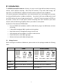
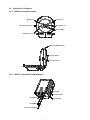
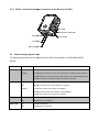
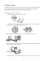
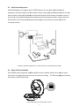
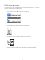
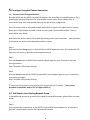
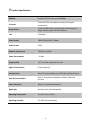
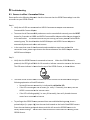
OP500 ConnectedLife
HD
D Camera
User's Manual
Table of Content
1. IMPORTANT INFORMATION ........................................................................................... 3
1.1.
IMPORTANT SAFETY NOTES ........................................................................................... 3
2. INTRODUCTION ............................................................................................................... 4
2.1.
PACKAGE CONTENT ...................................................................................................... 4
2.2.
DESCRIPTION OF EQUIPMENT ........................................................................................ 5
2.2.1.
OP500 CONNECTEDLIFE CAMERA ............................................................................. 5
2.2.2.
AX520 - CONNECTEDLIFE CAMERA ADAPTER ............................................................ 5
2.2.3.
AX510 - CONNECTEDLIFE ADAPTER (INCLUDED IN OP500-B STARTER KIT ONLY) ...... 6
2.3.
3.
UNDERSTANDING DIAGNOSTIC LEDS ............................................................................. 6
HARDWARE INSTALLATION ................................................................................................ 7
3.1.
MULTI-ROOM DEPLOYMENT .......................................................................................... 8
3.2.
MICRO-SD CARD INSTALLATION .................................................................................... 8
4.
OP500 CAMERA APP INSTALLATION.................................................................................. 9
5.
CREATING AN ENCRYPTED CAMERA CONNECTION ............................................................ 10
5.1.
CREATE A PRIVATE ENCRYPTED NETWORK ................................................................... 10
5.2.
ADD CAMERA TO AN EXISTING NETWORK GROUP ......................................................... 10
5.3.
REMOVING AN OP500 CAMERA FROM AN EXISTING NETWORK GROUP ........................... 11
6.
ENHANCING THE CONNECTEDLIFE NETWORK PERFORMANCE ........................................... 11
6.1.
AC OUTLET CONNECTIONS ......................................................................................... 11
6.2.
ELECTRICAL INTERFERENCE ........................................................................................ 11
7.
PRODUCT SPECIFICATIONS ............................................................................................. 12
8.
TROUBLESHOOTING ....................................................................................................... 13
8.1.
CAMERA IS OFFLINE / CONNECTION FAILURE ................................................................. 13
2
1. Important Information
1.1. Important Safety Notes
This device is intended for connection to the AC power line. For installation instructions, refer to
the Installation section.
The following precautions should be taken when using this product:
•
•
Please read all instructions before installing and operating this product.
Please keep all instructions for later reference.
•
•
Please follow all warnings and instructions marked on the product.
For safety reasons, this device should not be installed in any electric socket when being
powered on to prevent the venting holes from facing the floor.
•
•
•
•
Unplug the Powerline device from the wall outlet before cleaning.
Use a dry cloth for cleaning. do not use liquid cleaners or aerosol cleaners.
Do not operates this device near water.
This device should never be placed near or over a radiator, or heat register.
•
This device relies on the building’s electrical installation for short-circuit (over current)
protection.
•
•
Do not allow anything to rest on the device interconnect plug.
Do not place this device in a location where people may walk on the cords.
•
Because this device sends data over the power line, it is recommended that you plug it directly
into a power outlet.
•
Do not plug the device into a UPS or power strip with surge protection. (The device has its
own power filter for protection against surges.)
•
Only a qualified technician should service this device. Opening or removing covers may result
in exposure to dangerous voltage points.
•
Unplug the device from the wall outlet and refer the device to qualified service personnel if
the following occurs:
-
If the interconnect cords are damaged or frayed.
If liquid has been spilled onto the device.
-
If the device has been exposed to rain or water.
If the device does not operate normally when the operating instructions are followed.
If the device exhibits a distinct change in performance.
3
2. Introduction
The OP500 ConnectedLife Camera is a feature rich, easy to install, high definition home monitoring
solution, which redefines simplicity. With 720p HD resolution, 2-way
2 way audio, local storage, and
night vision, the OP500 delivers a superset of features when compared to the competition.
The OP500 implements HomePlug Power Line Communications (PLC) technology, which provides
the ultimate flexibility when it comes to installation. Any outlet in the
the home can be used to install
the OP500 without the worry of poor network quality. Unlike Wi-Fi
Wi Fi based cameras, the OP500 can
be placed in those hard to reach places without interfering with other devices on your home
network, while still delivering HD quality
qu
video to your tablet or smart phone.
Key features of the Neurona OP500 include:
•
Scan the OP500's QR code into a mobile or tablet device, plug it into ANY outlet, and start
monitoring
•
•
•
•
2-Way
Way audio leveraging a built in speaker and microphone
Keep video secure by storing locally using a microSD card
Video playback and activity alerts on mobile or tablet devices
Control the built-in, multi-color
color night light
•
Monitor dark rooms with enhanced night vision
2.1. Package Content
Before starting the installation of the device,
d
, please make sure the package contains the following
items:
OP500
OP500-B (Bundle)
AX520
OP500
OP500
AX510
AX520
OP500
OP500
Camera Adapter
Camera
QR Code Tag
Adapter
Camera Adapter
Camera
QR Code Tag
Manual
OP500 Quick Start Guide
OP500 Quick Start Guide
Installation
OP500 QR Code Tag for installation
i
OP500 QR Code Tag for
or Installation
Cables
None
RJ-45 Cable x 1
4
2.2. Description of Equipment
2.2.1. OP500 ConnectedLife Camera
Microphone
Light Sensor
3.5mm Audio Output Jack
Wide-Angle Lens
Infrared LEDs
Temperature Sensor
Multi-color LED Night Light
Internal Speaker
microSD Card Slot
2.2.2. AX520 - ConnectedLife Camera Adapter
Power LED
Camera Link LED
Group Button
PLC Link LED
Reset Button
Camera Port (w/power)
5
2.2.3. AX510 - ConnectedLife Adapter (Included in OP500-B
OP500 Starter Kit ONLY)
Power LED
Ethernet Link / Activity LED
Group Button
PLC Link LED
Reset Button
Ethernet
net (LAN) Port
2.3. Understanding
rstanding Diagnostic LEDs
The following table describes the operation of the LEDs incorporated in the AX510 and AX520
devices.
LED
Power LED
LED State
Description
OFF
Power off
Blinking
During Pairing Procedure (creating an encrypted PLC network). The PLC adapter or
camera adapter are creating or being joined into the same encrypted network and
will last for 2minutes until they are been succeeded or canceled.
PLC LED
On
PLC adapter or camera
ca
adapter is detected
Off
Neither PLC adapter nor camera
cam
adapter are detected
Blinking
a. Fast: Data transfer
transf rate is higher than 60Mbps
b. Normal: Data transfer rate is between 10 and 60Mbps
60
c. Slow: Data transfer rate is lower than 10 Mbps
Ethernet LED
Camera LED
On
Ethernet link detected
Off
Ethernet link is not detected
On
Camera link detected
Off
Camera link is not detected
6
3. Hardware Installation
The OP500 leverages the home's electrical wiring to create a whole home security and monitoring
network without the requirement of having a Wi-Fi network. To establish this security and
monitoring network, please follow the step-by-step instructions below.
Before getting started, please make sure:
•
The Broadband router
outer is connected to the Internet.
•
The AX510 and AX520 ConnectedLife Adapters are plugged directly
directly into the wall's power
outlet and not in a surge protector or power strip:
Step 1: Plug AX520 ConnectedLife Adapter to AC outlet anywhere in the house.
Step 2: Plug AX520 ConnectedLife Adapter to AC outlet and connect to router or broadband
modem
em with Ethernet cable (provided).
Note: Make sure LEDs illuminate on both the AX510 ConnectedLife Camera and AX520 ConnectedLife adapters.
7
3.1. Multi-Room Deployment
One AX510 Adapter can support up to 7 OP500 Cameras. You can place additional camera
anywhere in the house where you have a power outlet.
outlet Simply plug the additional camera into wall
outlet and the ConnectedLife Adapter
dapter will automatically detect and connect to the new camera. If
the existing ConnectedLife Adapter has established private encryption network, you can press the
Group button on the ConnectedLife and Camera
C
adapters, then the new camera will join the
encrypted network.
For further information, please go to 5.2 Add Camera to an Existing
Existing Network Group
3.2. Micro-SD Card Installation
Every OP500 camera ships with an 8GB microSD card pre-installed,, which can be used to record
events that are triggered by motion, or for continuous recording. The following diagram illustrates
the location of the microSD card:
A class 10 MicroSD card up to 64 GB is required.
8
4. OP500 Camera App Installation
The Neurona OP500 Camera is supported by both iOS and Android mobile devices. To install the
application, please follow the instructions below:
1. Download OP500
0 Camera App from App store or Google Play:
2. Locate the QR Code tag, which is attached to the OP500 cable:
3. Scan QR code, import, or manually type Camera
C
ID to add camera:
4. Activate the Camera by setting up Name and Password in the OP500 Camera App
A
9
5. Creating an Encrypted Camera Connection
5.1. Create a Private Encrypted Network
Both the AX510 and the AX520 ConnectedLife Adapters are HomePlug AV compatible device. Every
HomePlugAV compliant device has the same default network name, which enables them to
communicate with each other without requiring any special user configuration.
Users can easily create an encrypted network with 128-bit encryption for higher levels of security.
Simply press Group button to enable a hassle-free encrypted ConnectedLife network. To do so,
please follow steps below.
Note: Install the devices side by side to make the pairing process more convenient. After procedure
is completed, the device can be deployed anywhere at home.
Step 1:
Press and hold the Group button on both AX510 and AX520 adapters for over 10 seconds until LED
lights turns off and on to generate new encrypted network.
Step 2:
Press the Group button of AX510 ConnectedLife Adapter again for up to 3 seconds to start the
pairing procedure.
Note: The power LED will start blinking.
Step3 :
Press the Group button on the AX520 ConnectedLife Camera Adapter again for up to 3 seconds to
start pairing procedure.
Note: The power LED will start blinking.
To cancel the pairing process, press and hold the Group button for 2 seconds. Once pairing
procedure is completed, both of PLC LED lights will be on.
5.2. Add Camera to an Existing Network Group
To add additional cameras to an existing encrypted ConnectedLife network, please follow the steps
below:
Step 1:
Press and hold the Group button on the Ax520 ConnectedLife Camera Adapter for 10 seconds to
generate a new network name for the ConnectedLife network.
10
Step 2:
Press the Group button on the AX510 ConnectedLife Adapter for approximately 3 seconds in order
to start the pairing process.
Note: The power LED will start blinking.
Step 3:
Press the Group button on the AX520 ConnectedLife Camera Adapter from the new camera for up
to 3 seconds to start the pairing procedure.
Note: The power LED will start blinking
Once the pairing procedure is complete, the LED light on the new Ccamera will turn on.
5.3. Removing an OP500 Camera from an Existing Network Group
To remove an OP500 Camera from an existing encrypted ConnectedLife network, you can press the
RESET button on the OP500 camera that you want to remove. This will return the OP500 back to
its factory default settings.
6. Enhancing the ConnectedLife Network Performance
Neurona's ConnectedLife products leverage the home's existing electrical wiring to create a robust
ConnectedLife network, therefore the actual performance of the network, and therefore quality of
the OP500 video image may be affected by electrical noise. To improve the performance and video
quality of your ConnectedLife Camera, please refer to suggestions below while setting up your
ConnectedLife products
6.1. AC Outlet Connections
•
Avoid connecting Neurona products to an uninterruptible power supply (UPS) or backup
power supply device. For the best results, plug all ConnectedLife products directly into the
power outlet.
•
•
Avoid connecting high-power consuming appliances to the same power outlet.
Avoid plugging ConnectedLife products into power strips
6.2. Electrical Interference
Some household appliances may produce noise emission. If this noise emission spreads over the
home's electrical wiring it will affect your ConnectedLife network performance. For the best
possible results, we recommend using an electrical noise filter with products / appliances such as:
• Battery chargers (including cell phone chargers), Vacuum cleaners, Hair dryers, Halogen light,
Power drills, Lights or lamps with touch-sensitivity feature supported
11
7. Product Specifications
Network
Processor
Image Sensor
Interface PLC PHY rate: Up to 500Mbps
32-bit RISC CPU with hardware video processing &
compression
1/4-inch CMOS sensor. automatically controls dynamic
range, exposure, gain and white balance
Lens
1.3M pixel
Video Quality
1280x720 @10 fps/ 1.5Mbps
Video Format
H.264
Network Requirement
TCP/UDP and DHCP
Power Consumption
~ 5 Watt
Supported OS
iOS 7.0 or later, Android 4.0 or later
Night Vision Distance
9 Feet (3 Meters)
Storage Device
Micro SD card available; up to 64GB @ class10 and above
Dual Directional Audio
Built-in microphone & speaker for Walkie- Talkie like
function
Sensor Detection
Motion / Temperature detection
Night Light
Multiple colors with fading effect
Operating Temperature
0 to 40 °C (32 to 104 °F)
Operating Humidity
20 ~ 90% Non-Condensing
12
8. Troubleshooting
Connectio Failure
8.1. Camera is offline / Connection
Please perform the following diagnostic
agnostic checks in the
he event that the OP500 Camera App is not able
to connect to your OP500 Camera:
Step 1:
•
•
•
Verify that all LEDs are illuminated
illuminate on AX510 ConnectedLife
nnectedLife Adapter and the AX520
ConnectedLife Camera Adapter.
Adapte
To ensure that all ConnectedLife products are on
on the same default network, press the RESET
button for 2 seconds on AX510 and AX520 ConnectedLife Adapters while they are plugged in
to the wall outlet. This will ensure that they are utilizing the factory default ConnectedLife
network group. This should enable the AX510 Adapter and AX520 Camera Adapter to
automatically detect each other and connect.
In
n the event that none of the aforementioned remediation steps have resolved the
connection issues, please
lease try to shorten the distance between the AX510 Adapter
dapter and the
AX520 Camera Adapter.
Step 2:
• Verify that the OP500 Camera is connected to Internet. When the OP500 Camera
C
is
powered, the LED light will blink for 10 seconds to indicate connection status to the Internet.
The LED status indicator is located on the top of the OP500 Camera,, as shown below:
• The status of the OP500 Camera's connection to the Internet can be determined using the
followingg explanation of the LED behavior:
o Successful Internet connectivity is indicated by solid white LED
o If the LED is blinking on and off slowly (i.e. every 1.2 seconds), then verify that the
AX510 is connected to the Internet router
o If the LED is blinking rapidly (i.e. every 0.8 seconds), then verify that the Internet
router has a connected to Internet
•
To you forget the OP500 Camera password that was established during setup, insert a
pointed object (i.e. paper clip)
clip into the reset hole located on the back of the OP500 camera.
Press the reset button gently and release,
release, and this will return the OP500 Camera to its
factory default settings. You will then need to follow the instructions for installing a new
OP500 Camera.
13