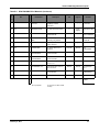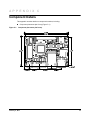
1
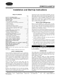
Stellaris® Intelligent Display Module Single-Board Computer (IDM-SBC) Reference Design Kit User ’s Manual RDK-IDM-SBC-UM-03 Co pyrigh t © 2 009– 201 0 Te xas In strumen ts Copyright Copyright © 2009–2010 Texas Instruments, Inc. All rights reserved. Stellaris and StellarisWare are registered trademarks of Texas Instruments. ARM and Thumb are registered trademarks, and Cortex is a trademark of ARM Limited. Other names and brands may be claimed as the property of others. Texas Instruments 108 Wild Basin, Suite 350 Austin, TX 78746 http://www.ti.com/stellaris 2 February 9, 2010 Stellaris® IDM Single-Board Computer Table of Contents Chapter 1: Stellaris® Intelligent Display Module Single-Board Computer RDK Overview ........................ 9 Kit Contents ...................................................................................................................................................... 10 Using the RDK .................................................................................................................................................. 10 Features............................................................................................................................................................ 11 Board Overview ................................................................................................................................................ 12 Board Specifications ..................................................................................................................................... 12 Chapter 2: Hardware Description .................................................................................................................. 13 Block Diagram .................................................................................................................................................. 13 Functional Description ...................................................................................................................................... 14 Microcontroller .............................................................................................................................................. 14 Debugging..................................................................................................................................................... 14 Expansion Connector.................................................................................................................................... 14 Power and Interface Terminal Block ............................................................................................................. 15 Clocking ........................................................................................................................................................ 15 Reset............................................................................................................................................................. 15 SDRAM ......................................................................................................................................................... 15 Power Supplies ............................................................................................................................................. 16 USB............................................................................................................................................................... 16 Ethernet ........................................................................................................................................................ 16 Color QVGA LCD Touch Panel..................................................................................................................... 16 I2S Audio....................................................................................................................................................... 18 Controller Area Network (CAN)..................................................................................................................... 18 Serial Flash and microSD Card .................................................................................................................... 18 Chapter 3: Software Development ................................................................................................................ 21 Software Description......................................................................................................................................... 21 Source Code..................................................................................................................................................... 21 Tool Options ..................................................................................................................................................... 21 Programming the IDM-SBC .............................................................................................................................. 22 Appendix A: Schematics................................................................................................................................ 25 Appendix B: Bill of Materials (BOM) ............................................................................................................. 29 Appendix C: Component Details ................................................................................................................... 33 February 9, 2010 3 4 February 9, 2010 Stellaris® IDM Single-Board Computer List of Tables Table 2-1. Table 2-2. Table 2-3. Table 2-4. Table B-1. LCD-Related Signals..................................................................................................................... 17 I2S Audio-Related Signals............................................................................................................. 18 CAN-Related Signals .................................................................................................................... 18 Serial Flash and microSD-Related Signals ................................................................................... 19 RDK-IDM-SBC Bill of Materials ..................................................................................................... 29 February 9, 2010 5 6 February 9, 2010 Stellaris® IDM Single-Board Computer List of Figures Figure 1-1. Figure 1-2. Figure 2-1. Figure 2-2. Figure 2-3. Figure 2-4. Figure C-1. Intelligent Display Module Single-Board Computer......................................................................... 9 IDM-SBC Board Overview Diagram .............................................................................................. 12 Intelligent Display Module Single-Board Computer Block Diagram .............................................. 13 Debug Connection Pinout ............................................................................................................. 14 Expansion Connector .................................................................................................................... 14 Pluggable Terminal Blocks............................................................................................................ 15 Component placement plot for top ................................................................................................ 33 February 9, 2010 7 8 February 9, 2010 C H A P T E R 1 Stellaris® Intelligent Display Module Single-Board Computer RDK Overview The Stellaris® Intelligent Display Module Single-Board Computer (RDK-IDM-SBC) is a reference design for a complete QVGA touch-screen user interface for control, automation, and instrumentation applications. The design features the powerful Tempest-class LM3S9B92 microcontroller. The IDM-SBC offers USB, Ethernet, CAN, 8 MB of SDRAM, 1 MB of serial Flash, integrated 256 KB flash, and 96 KB SRAM, and provides simplified software development for the RDK using The Stellaris comprehensive graphics library and ARM development tools from ARM tools partners. The 8 MB of SDRAM is connected to the LM3S9B92 microcontroller using the External Peripheral Interface (EPI) bus available as a feature on Tempest-class devices. The efficient performance and robust integration of an ARM® Cortex™-M3 microcontroller, positions the IDM-SBC for use in building access controllers and security systems, intelligent white goods and home appliances, thin clients, and factory automation applications. This user's manual provides comprehensive information on the reference design hardware and software. Figure 1-1. February 9, 2010 Intelligent Display Module Single-Board Computer 9 Stellaris® Intelligent Display Module Single-Board Computer RDK Overview Kit Contents The RDK-IDM-SBC reference design kit contains everything needed to develop and run a range of applications using Stellaris microcontrollers: IDM-SBC board 8 Ω Speaker Retractable ethernet cable USB flash memory stick microSD card Power supply adaptor cable 2-position and 6-position terminal blocks 24 V wall power supply with international plug-set MDL-ADA2 10-pin to 20-pin JTAG adapter module Reference Design Kit CD with tools, complete documentation, and source code including: – Quickstart Guide – User’s Manual – Software Reference Manual – Board Data Sheet – BOM – Schematics – Gerber files The source code can be modified and compiled using any of the following tools: Keil™ RealView® Microcontroller Development Kit (MDK-ARM) IAR Embedded Workbench Code Sourcery GCC development tools Code Red Technologies development tools Texas Instruments’ Code Composer Studio™ IDE Using the RDK The recommended steps for using the RDK are: 10 Follow the Quickstart guide included in the kit. The Quickstart guide will help get the display module up and running in minutes. Use your preferred ARM tool-chain and the Stellaris Graphics library to develop touch-panel, USB, and Ethernet applications. Software applications can be loaded into IDM flash memory using either the Ethernet boot loader or a JTAG/SWD debug interface. See Chapter 3, “Software Development,” for the programming procedure. The Stellaris Graphics Library Software Reference Manual and the Stellaris Peripheral Driver Library Software Reference Manual each contain specific information on software structure and function. Customize and integrate the hardware to suit an end application. This user's manual is an important reference for understand circuit operation and completing hardware modification. February 9, 2010 Stellaris® IDM Single-Board Computer Features The RDK-IDM-SBC reference design kit provides the following features: Bright QVGA LCD touch-screen display – 262 K colors, 3.5" QVGA 320 x 240 pixels – White LED backlight with resistive touch panel Advanced audio – I2S mono Codec for high-quality audio – 0.8 W amplifier directly drives external 8-Ohm speaker Serial connectivity options – USB 2.0 Host – 10/100 Ethernet MAC and PHY – 1 MBPS Controller Area Network (CAN) – I2C Interface for external peripherals and sensors – UART serial port with TTL signal levels High performance microcontroller – 32-bit ARM® Cortex™-M3 core – 256 KB single-cycle flash, 96 KB single-cycle SRAM – 80 MHz operation Versatile board-level memories – 8 MB SDRAM connected by EPI – 1 MB serial flash connected by SPI – microSD card slot – USB Host connector for external mass-storage devices Power supply – Wide input range 12-40 Vdc power supply with auxiliary 5 V power output Screw terminal block for I2C, CAN, and power connections Compact 2.0” x 3.0” PCB footprint Easy to customize – Includes full source code, example applications, and design files – Develop using tools supporting Keil™ RealView® Microcontroller Development Kit (MDK-ARM), IAR Embedded Workbench, Code Sourcery GCC development tools, Code Red Technologies development tools, or Texas Instruments’ Code Composer Studio™ IDE (using a Stellaris evaluation kit or preferred ARM Cortex-M3 debugger) – Supported by Stellaris Graphics Library and StellarisWare® Peripheral Driver Library – Comes with factory-programmed quickstart game demo application – Ethernet boot loader for firmware update February 9, 2010 11 Stellaris® Intelligent Display Module Single-Board Computer RDK Overview Board Overview Figure 1-2 shows an overview of the board. Figure 1-2. IDM-SBC Board Overview Diagram Audio Connector Flex cable to LCD Touch Panel I2S Audio CODEC Integrated Power supply Power and Ground Test Points JTAG/SWD Connector Stellaris LM3S39B92 Microcontroller UART/Expansion 8MB SDRAM microSD Card Slot 1MB Serial Flash CAN Transceiver Power Terminals GND CAN L CAN H +5V I2C SDA I2C SCL GND USB Host +10-40V I2C and CAN Terminals 10/100 Ethernet Board Specifications The following list shows the IDM-SBC’s board specifications: Board supply voltage range: 10-40 Vdc Board supply current with 24 V supply – 55 mA (1.3 W) when running qs-blox application at 50 MHz 5 V power output (for USB Host or +5 V terminal) – 5 V +/- 5% at 500 mA Dimensions (excluding LCD panel): • 2.00” x 3.00” x 0.60” (L x W x H) Speaker – Impedance: 8 Ω (±1 Ω) – Output power: 0.8 W – Format: Mono 12 RoHS status: Compliant February 9, 2010 C H A P T E R 2 Hardware Description The IDM-SBC design uses a Stellaris® LM39B92 microcontroller to handle display functions, touch-screen control, Ethernet, USB, CAN, and other peripheral functions. Only a few additional ICs are necessary to complete the design. The entire circuit is built on a compact four-layer printed circuit board. All design files are provided on the RDK-IDM-SBC CD. Block Diagram Figure 2-1 shows the IDM-SBC block diagram. Figure 2-1. Intelligent Display Module Single-Board Computer Block Diagram RJ45 Jack+ Magnetics Ethernet Touch QVGA Color LCD Module Debug Data 8MB SDRAM EPI USB Type-A Connector USB Host USB 1GB 1MB Serial Flash Stellaris LM3S9B92 Microcontroller Speaker I2S +5V host supply MicroSD card slot SPI Control Audio CODEC and Amp +5V Power Terminal Block DC In 12-40V +3.3V Regulator Step-down switching regulator CAN PHY CAN CAN I2C UART0 Expansion I/O Terminal Block IDM Single Board Computer February 9, 2010 13 Hardware Description Functional Description This section describes the IDM-SBC’s hardware design in detail. Microcontroller The Stellaris LM39B92 is an ARM Cortex-M3-based microcontroller with 256-KB flash memory, 80-MHz operation, Ethernet, USB, EPI and a wide range of peripherals. See the LM39B92 data sheet (order number DS-LM39B92) for complete device details. The IDM-SBC’s LM39B92 microcontroller is factory programmed with a quickstart demo program. The quickstart program resides in on-chip flash memory and runs each time power is applied, unless the quickstart has been replaced with a user program. Debugging The microcontroller supports JTAG and SWD debugging as well as SWO trace capabilities. To minimize board area, the IDM-SBC uses a 0.050” pitch header (J6) which matches ARM’s fine-pitch definition (Figure 2-2). Some in-circuit debuggers provide a matching connector. Other debuggers can be used with the MDL-ADA2 adaptor board included in the RDK. Figure 2-2. Debug Connection Pinout 1 2 3.3V GND GND n/c GND TMS/ SWDIO TCK/ SWCLK TDO TDI SRSTn 9 10 Expansion Connector UART0 signals from the microcontroller are available on J4, an internal expansion connector. The pin-out of this connector is compatible with the power/UART cable used by the ICDI board included in the EK-LM3S9B90 and EK-LM3S9B92 evaluation kits. This then provides a convenient Virtual Com port interface to a PC. A pair of I2C signals are also available, however, jumpers connecting SCL and SDA are normally omitted to avoid conflict with digital signals from the ICDI board. Figure 2-3. Expansion Connector1 1 2 UART0 TX UART0 RX SCL (opt) n/c SDA (opt ) GND GND n/c 7 8 1. Revision A PCBs transpose UART0 RX and TX signals and are, therefore, incompatible with ICDI connections. 14 February 9, 2010 Stellaris® IDM Single-Board Computer Power and Interface Terminal Block Power, CAN, and I2C interfaces are provided through 3.5 mm pluggable terminal blocks. For convenience, the RDK includes the plugs. See the BOM for complete part numbers. I2C SDA I2C SCL GND CAN L CAN H +5V Pluggable Terminal Blocks +10-40VDC GND Figure 2-4. I2C is a short-distance intra-device bus that can be used to add capabilities such as an ADC (for analog measurement) or digital inputs and outputs. CAN is best suited for communication between devices. Refer to the CAN specification for complete details on data rates and bus length. Clocking The IDM-SBC board uses a 16.0-MHz (Y2) crystal to complete the LM3S9B92 microcontroller's main internal clock circuit. An internal PLL, configured in software, multiples this clock to higher frequencies for core and peripheral timing. A 25.0 MHz (Y1) crystal provides an accurate timebase for the Ethernet PHY. Reset The RESETn signal into the LM3S39B92 microcontroller connects to the JTAG/SWD debug connector and to a simple R-C filter circuit to extend reset timing at power up. The LCD Module has special Reset timing requirements requiring a dedicated control line from the microcontroller. SDRAM The LM3S9B92 features an External Peripheral Interface (EPI) module, a high-speed 8/16/32-bit parallel bus for connecting external peripherals or memory without glue logic. Supported modes include SDRAM, SRAM and Flash memories, as well as Host-bus and FIFO modes. On the IDM-SBC, the SDRAM device interfaces directly to the EPI and adds 8MB of memory (4M x 16) which, once configured, becomes part of the LM3S9B92’s memory map at either 0x6000.0000 or 0x8000.0000. The SDRAM interface multiplexes DQ00..14 and AD/BA0..14 without requiring external latches or buffers. Of the 32 EPI signals, only 24 are used in SDRAM mode, with the remaining signals used for non-EPI functions on the board. February 9, 2010 15 Hardware Description Power Supplies The RDK-SBC has a wide input range switching-power supply that creates a 5V 1A rail for board operation. The LM22672 step-down regulator switches at 500KHz with an efficiency of greater than 90%. Board functions require only about 150 mA with the remaining capability available for external interfaces such as USB host. A low drop-out (LDO) regulator (U7) converts the +5V power rail to +3.3V to power digital devices including the microcontroller and SDRAM. USB The LM3S9B92’s full-speed USB controller is configured for Host mode, allowing the SBC to connect directly to USB Flash sticks and other USB devices. U9, a fault-protected switch, controls and monitors power to the USB host port. USB_EPEN, the control signal from the microcontroller, has a pull-down resistor to ensure host-port power remains off during reset. The power switch will immediately cut power if the attached USB device draws more than 1 Amp, or if the switches’ thermal limits are exceeded by a device drawing more than 500mA. USB_PFLT indicates the over-current status back to the microcontroller. Ethernet With its fully integrated 10/100 Ethernet MAC and PHY, the LM3S9B92 requires only a standard Jack with integrated magnetics and a few passive components. The TX and RX signals are routed to the jack as a differential pair. The PHY incorporates MDI/MDI-X cross-over, so the function of the TX and RX pairs can be swapped in software. The Ethernet jack incorporates two status LEDs that can be controlled directly by the Ethernet PHY or by those same pins in GPIO mode. Color QVGA LCD Touch Panel The IDM-SBC features a TFT Liquid Crystal graphics panel with 320 x 240 pixel resolution. The face of the panel is protected during shipping by a thin, protective plastic film which should be removed before use. The panel should be laid on a flat surface during evaluation, to protect it from damage and maximize the sensitivity of the touch screen. Features Features of the LCD Panel include: – Kitronix K350QVG-V1-F display – 320 x RGB x 240 dots – 3.5” 262K colors – Wide temperature – White LED backlight – Integrated RAM – Resistive touch panel 16 February 9, 2010 Stellaris® IDM Single-Board Computer Control Interface The Color LCD module has a built-in controller IC with a multi-mode parallel interface. The EVB uses an 8-bit 8080 type interface with GPIO Port D providing the data bus. Table 2-1. LCD-Related Signals Microcontroller Pin Board Function PE6/ADC1 Touch X+ PE3 Touch Y- PE2 Touch X- PE7/ADC0 Touch Y+ PB7 LCD Reset PD0..7 LCD Data Bus 0..7 PH7 LCD Data/Control Select PB0 LCD Read Strobea PH6 LCD Write Strobe PJ7 Backlight control a. LCD Read function not available on LM3S9B92 Rev B1. See rework note in schematic. Backlight The white LED backlight must be powered for the display to be clearly visible. U9 (FAN5331B) implements a 20mA constant-current LED power source to the backlight. The backlight is controlled by the microcontroller using GPIO PJ7. The timer connected to this pin could be configured to provide a modulated dimming signal Because the FAN5331B operates in a constant current mode, its output voltage will jump up if the LCD should become disconnected. To prevent over-voltage failure of the IC or diode D5, a zener (D6) clamps the voltage. The current will limit to 20mA, but the total board current will be higher than when the LCD panel is connected. If the LCD is not connected, avoid over-heating the backlighting circuit, by setting PJ7 low to completely shut-down the circuit. Power The LCD module has internal bias voltage generators and requires only a single 3.3V dc supply. Resistive Touch Panel The 4-wire resistive touch panel interfaces directly to the microcontroller, using 2 ADC/GPIO channels and 2 GPIO-only signals. The microcontroller creates a resistive divider by driving Y+ and Y- with 3.3V (VOH) and 0V (VOL) respectively. A voltage representing the Y-axis position is then read on the X+ terminal. The process then repeats for the other axis. Note that when the screen is not being touched, the X+ or Y+ sense inputs are floating. The software implements a special state to discharge the capacitor (C10 or C15) to 0V and detect this condition. Refer to the StellarisWare® source code for additional information on touch panel implementation. February 9, 2010 17 Hardware Description I2S Audio The IDM-SBC has advanced audio capabilities using an I2S-connected Wolfson WM8510 CODEC. The CODEC’s integrated amplifier can directly drive an 8 Ω speaker. Although the CODEC supports a microphone input, pin count limits on the LM3S9B92 result in this feature being unconnected. The Microphone signals are still routed to connector J8 in-case the user wishes to wire the ADCDAT signal to the LM3S9B92. Table 2-2. I2S Audio-Related Signals Microcontroller Pin Board Function PB3/I2C0SDA CODEC Configuration Data PB2/I2C0SCL CODEC Configuration Clock PE5/I2STXSD Audio Out Serial Data PE4/I2STXWS Audio Out Framing signal PB6/I2STXSCK Audio Out Bit Clock PF1/I2STXMCLK Audio Out System Clock The Audio CODEC has a number of control registers which are configured using the I2C bus signals. CODEC settings can only be written, but not read, using I2C. Refer to the StellarisWare® example applications for programming information and to the WM8510 data sheet for complete register details. In the default configuration, the LM3S9B96 provides the master Bit Clock (BCLK) and System Clock (MCLK) to the CODEC. Since the CODEC has only one set of clock I/Os for both audio-out and audio-in functions, only the LM3S9B96 I2S module transmit clocks are connected. DriverLib provides I2S source code, with most examples showing Audio Output. Controller Area Network (CAN) Controller Area Network (CAN) is a multicast, shared serial bus standard for connecting automotive or industrial systems. The IDM-SBC board includes a CAN transceiver (U5) capable of communicating at up to 1Mb/s. The end-points of the CAN bus should be properly terminated with 120Ù resistors. Table 2-3. CAN-Related Signals Microcontroller Pin Board Function PB5/CAN0TX CAN Transmit Data PB4/CAN0RX CAN Receive Data Serial Flash and microSD Card To supplement the LM3S9B92 microcontroller’s internal Flash memory, the IDM-SBC board includes a 1MB on-board serial Flash memory and a microSD card slot. Both devices share a SPI 18 February 9, 2010 Stellaris® IDM Single-Board Computer (Serial Peripheral Interface) bus. These memories are typically used for data storage and for large code images which are copied into SDRAM for execution. Table 2-4. Serial Flash and microSD-Related Signals Microcontroller Pin Board Function Jumper Name PA2/SSI0CLK Clock from SPI module SCLK PA3 microSD Card chip select SDCSn PA4/SSI0RX Receive data from SPI module MISO PA5/SSI0TX Transmit data from SPI module MOSI PF0 Serial Flash chip select FLCSn The microSD card is used in SPI mode. 4-bit and 1-bit SD card modes are not supported. February 9, 2010 19 Hardware Description 20 February 9, 2010 C H A P T E R 3 Software Development This chapter provides general information on software development as well as instructions for Flash memory programming. Software Description The software provided with the IDM-SBC provides access to all of the peripheral devices supplied in the design. The Stellaris Peripheral Driver Library is used to operate the on-chip peripherals, the Stellaris Graphics Library is used to render graphical displays on the touch screen, and a set of board-specific drivers are provided to access the off-chip functionality on the IDM-SBC. The Stellaris Graphics Library provides two levels of support for rendering graphical elements. In the lowest level, basic drawing primitives are provided, such as lines, circles, rectangles, and text rendering. Each primitive supports clipping to a single clipping rectangle, allowing only a portion of the display to be affected by the drawing primitives. Building upon the drawing primitives is a widget set, which combines the drawing of graphical elements with reactions to pointer events (in this case, presses on the touch screen). The widget set includes push buttons, check boxes, radio buttons, sliders, listboxes, and drawing canvases. By using the widget set, complex interactive graphical displays can be constructed quickly. A set of drivers for the on-board peripherals is also provided. This includes a driver for the touch screen, the audio codec, the USB, CAN, and the microSD card. Ethernet is supported by TCP/IP stacks and example applications, all within the StellarisWare® libraries. The IDM-SBC is also supplied with a set of example applications that utilize the Stellaris Peripheral Driver Library and the Stellaris Graphics Library, along with the board-specific drivers for the on-board peripherals. These applications demonstrate the capabilities of the IDM-SBC, and provide a starting point for the development of the final application for use on the IDM-SBC. All example applications are integrated with the Stellaris boot loader to allow automatic firmware updates to be performed over the serial port using the LM Flash Programmer application. Source Code The complete source code for the IDM-SBC is included on the RDK-IDM-SBC CD. See the Quickstart Guide for a detailed description of initial RDK hardware set up and how to install the source code. The source code and binary files are installed in the DriverLib tree. Tool Options The source code installation includes directories containing projects and/or makefiles for the following tool-chains: February 9, 2010 • Keil™ RealView® Microcontroller Development Kit (MDK-ARM) • IAR Embedded Workbench • Code Sourcery GCC development tools • Code Red Technologies development tools • Texas Instruments’ Code Composer Studio™ IDE 21 Software Development Evaluation versions of these tools may be downloaded from www.ti.com/stellaris. Note that, due to code size restrictions, the evaluation versions of the tools may not build all example programs for the IDM. A full license is necessary to re-build or debug all examples. Instructions on installing and using each of the evaluation tools can be found in the Quickstart guides (for example, Quickstart-Keil, Quickstart-IAR) which are available for download from the evaluation kit section of our web site at www.ti.com/stellaris. For detailed information on using the tools, refer to the documentation included in the tool chain installation or visit the website of the tools supplier. Programming the IDM-SBC The IDM-SBC software package includes pre-built binaries for each of the example applications. If you installed DriverLib to the default installation path of C:\STELLARISWARE, you can find the example applications for the IDM in “C:\STELLARISWARE\BOARDS\RDK-IDM-SBC”. The Stellaris LM Flash Programmer is a free tool for programming Stellaris microcontrollers. It can be used in two modes to update the firmware on the IDM-SBC. Most IDM-SBC example applications are designed for use with the Stellaris boot loader which supports updating of the main application firmware over Ethernet (this requires a board with Rev C or later of the LM39B92 microcontroller). Alternatively, the LM Flash Programmer utility can be used in conjunction with any Stellaris evaluation board to program the IDM-SBC. The Stellaris evaluation board acts as a USB-to-JTAG/SWD hardware interface and should be used in cases where the boot loader image is not present or where the main application image is not behaving correctly and cannot transfer control to the boot loader. However, in normal operation, it is more convenient to program via Ethernet. To program example applications into the IDM-SBC using the Ethernet-based firmware update (this requires a board with Rev C or later of the LM39B92 microcontroller): 1. Install the LM Flash Programmer utility on a Windows PC. 2. Ensure that the IDM is connected to the same subnet of your Ethernet as the Windows PC that will be used to program the device. 3. Apply power to the IDM. 4. Run LM Flash Programmer. 5. In the Configuration tab, select “Manual Configuration - see below” in the “Quick Set” list. 6. Select “Ethernet Interface” in the list below “Interface” and fill in the IP and MAC addresses for the IDM you are trying to program. Each example application shows this information somewhere on the IDM display. Note that it may take several seconds for the IP address to be allocated. 7. If your PC has multiple network adapters, select the appropriate adapter in the “Ethernet Adapter” list. 8. Move to the Program tab and click the Browse button. Navigate to the example applications directory (the default location is “C:\STELLARISWARE\BOARDS\RDK-IDM-SBC””. 9. Each example application has its own directory. Navigate into the example directory that you want to load and then go to the /gcc directory which contains the binary (*.bin) files. Select the application binary file and click Open. Files that start with a “bl_” prefix are boot loader images and cannot be updated using this method. 10. Click the Program button to start the download process. 11. The program starts once the download is complete. 22 February 9, 2010 Stellaris® IDM Single-Board Computer To replace the boot loader image or to program example applications into the IDM-SBC using a Stellaris evaluation board to provide JTAG/SWD functionality: 1. Install LM Flash Programmer on a Windows PC. 2. Connect the MDL-ADA2 10-pin to 20-pin adapter (included in the RDK) to the evaluation board ribbon cable. This converts the standard 20-pin ARM header on the evaluation board to a fine pitch ARM header. 3. Carefully connect the socket of the adaptor board to J1 on the IDM. 4. Apply power to the IDM and connect the evaluation board (available separately) to a USB port. 5. Run LM Flash Programmer. 6. In the Configuration Tab use the Quick Set control to select LM39B92. 7. Move to the Program Tab and click the Browse button. Navigate to the example applications directory (the default location is “C:\STELLARISWARE\BOARDS\RDK-IDM-SBC). 8. Each example application has its own directory. Navigate into the example directory that you wish to load and then into the /gcc directory which contains the binary (*.bin) files. Files named with a “bl_” prefix are Stellaris boot loader images while those without the prefix are main application images. Select the binary file and click Open. 9. Set the “Erase Method” to “Erase Necessary Pages” and check the “Verify After Program” box. NOTE: Setting “Erase Entire Flash” when attempting to replace a main application image will erase the boot loader image and result in a hang when the IDM next boots. If this occurs, reflash a boot loader image using these instructions. 10. If flashing a boot loader image, set the “Program Address Offset:” value to 0x0000. If programming a main application image, set this value to 0x1000. 11. Next, click on the Program button to start the Erase, Download, and Verify process. 12. Program execution will start once Verify is complete. The Debuggers in each of the tool-chains also include Flash programming capabilities, including support for high-performance in-circuit debug interfaces. February 9, 2010 23 Software Development 24 February 9, 2010 A P P E N D I X A Schematics This sections contains the schematic diagrams for the Intelligent Display Module Single-Board Computer. IDM-SBC Microcontroller, SDRAM, USB, and Ethernet on page 26 IDM-SBC LCD Panel, Serial Memory, and Audio on page 27 IDM-SBC Power and Interface on page 28 February 9, 2010 25 Schematic page 1 1 2 3 Note: UART0 Connections (as shown) are transposed on Rev A PCB. Expansion J4 J5 JTAG/SWD 2 4 6 8 10 47 28 29 30 31 FLASH_CSn SSI0CLK SDCARD_CSn SSI0RX SSI0TX R25 10K XTMS XTCK XTDO XTDI RSTn 90 6 5 61 I2STXSCK I2STXWS I2STXSD I2STXMCLK CON-HDR-2X5-050 80 79 78 77 8MB SDRAM B AD0 AD1 AD2 AD3 AD4 AD5 AD6 AD7 2 4 5 7 8 10 11 13 AD8 AD9 AD10 AD11 D12 BA0/D13 BA1/D14 D15 42 44 45 47 48 50 51 53 DQ0 DQ1 DQ2 DQ3 DQ4 DQ5 DQ6 DQ7 36 40 BA0 BA1 CS WE RAS CAS CLK CKE DQMH DQML NC NC 1 14 27 3 9 43 49 C A0 A1 A2 A3 A4 A5 A6 A7 A8 A9 A10 A11 DQ8 DQ9 DQ10 DQ11 DQ12 DQ13 DQ14 DQ15 +3.3V VDD VDD VDD VDDQ VDDQ VDDQ VDDQ VSS VSS VSS VSSQ VSSQ VSSQ VSSQ 23 24 25 26 29 30 31 32 33 34 22 35 AD0 AD1 AD2 AD3 AD4 AD5 AD6 AD7 AD8 AD9 AD10 AD11 20 21 BA0/D13 BA1/D14 19 16 18 17 CSn WEn RASn CASn 38 37 39 15 SDCLK SDCKE DQM1 DQM0 R24 10K C33 0.1UF 83 84 25 24 23 22 86 85 74 75 76 63 42 19 18 41 14 87 39 50 52 53 54 36 64 XTLN XTALP 17 16 OSC0 OSC1 1 Y1 48 49 Y2 2 25.00MHz R10 16.00MHz C20 C21 C22 C23 10PF 10PF 10PF 10PF 33 12.4K 51 +3.3V C16 0.01UF C17 0.01UF C18 0.1UF 3 D 4 Date 25 Feb 09 A 15 Apr 09 First production release. Incorporates errata. 21 Apr 09 Add rework annotation (PB0/LCD_RDn) 18 May 09 Add notation about UART0 signal transposition. 6 Oct 09 PH3/EPI0S00 PH2/EPI0S01 PC4/EPI0S02 PC5/EPI0S03 PC6/EPI0S04 PC7/EPI0S05 PH0/EPI0S06 PH1/EPI0S07 PE0/EPI0S08 PE1/EPI0S09 PH4/EPI0S10 PH5/EPI0S11 PF4/EPI0S12 PG0/EPI0S13 PG1/EPI0S14 PF5/EPI0S15 PJ0/EPI0S16 PJ1/EPI0S17 PJ2/EPI0S18 PJ3/EPI0S19 PJ4/EPI0S28 PJ5/EPI0S29 PJ6/EPI0S30 PG7/EPI0S31 PB5/U1TX/CAN0TX PB4/CAN0RX PD0 PD1 PD2 PD3 PD4 PD5 PD6 PD7 PB0 PB7/NMI PH6 PH7 PJ7/CCP0 PE2 PE3 PE6/ADC1 PE7/ADC0 USB0DM USB0DP USB0RBIAS PF2/LED1 PF3/LED0 MDIO TXOP TXON RST_n XTLN XTLP RXIN Initial Prototype 9 21 45 57 69 82 94 Fix UART0 signal transposition. 72 65 USB_EPE USB_PFLT I2C_SCL I2C_SDA CAN Transceiver I2C_SCL I2C_SDA 10 11 12 13 97 98 99 100 1 4 LCD_D0 LCD_D1 LCD_D2 LCD_D3 LCD_D4 LCD_D5 LCD_D6 LCD_D7 8 2 TXD RXD CANH 7 6 CANH CANL CANL +5V RS GND 3 5 VCC VREF C41 0.1UF J1 66 89 62 15 55 LCD_D[0..7] +VBUS 95 96 2 1 3 D- D+ G 6 1 2 3 4 TOUCH_XN TOUCH_YN TOUCH_XP TOUCH_YP D1 B72590D0050H160 70 71 B D3 B72590D0050H160 R11 9.10K +3.3V 60 59 58 Ethernet 10/100baseT J6 R12 10K +3.3V +3.3V R13 49.9 R15 49.9 C31 10pF R17 C34 10pF 330 43 +3.3V 3 R26 7 R27 R14 49.9 ERBIAS R16 49.9 C32 10pF 4 5 RX- 6 7 C 8 8 R18 +3.3V C35 10pF RX+ 3 1CT:1 6 10 37 TX+ 1 TX- 2 4 40 +3.3V G1CT:1 5 10 46 G+ 12 11 330 2 1 Y- 9 10 NC Y+ GND +3.3V NC J3011G21DNL VDDA GNDA GND GND GND GND GND GND GND +3.3V VDD VDD VDD VDD VDD VDD VDD VDD LDO VDDC VDDC 8 20 32 44 56 68 81 93 C25 C27 C29 0.01UF 0.01UF 0.1UF +3.3V C38 0.01UF C36 2.2UF U10 FAN2558S12X 7 5 38 88 C26 C28 0.01UF 0.1UF VOUT U16 Required only for LM3S9B96 Rev B1. See errata. C40 0.1UF +5V VIN C30 2.2UF C39 0.1UF EN PG 1 D 3 4 Drawing Title: Intelligent Display Module SBC Page Title: Micro, SDRAM, USB and Ethernet Size Date: 2 154-UAR42-E V 5 LCD_RSTn LCD_WRn LCD_DC BLON LM3S9B92 1 USB Host SN65HVD1050D LCD_D[0..7] 73 A U5 91 92 OSC0 OSC1 Description 0 B PC0/TCK/SWCLK PC1/TMS/SWDIO PC2/TDI PC3/TDO/SWO C24 0.1UF History Revision PB6/I2S0TXSCK PE4/I2S0TXWS PE5/I2S0TXSD PF1/I2S0TXMCLK PB2/I2C0SCL PB3/I2S0SDA RXIP 28 41 54 6 12 46 52 MT48LC4M16A2 +3.3V AD0 AD1 AD2 AD3 AD4 AD5 AD6 AD7 AD8 AD9 AD10 AD11 D12 BA0/D13 BA1/D14 D15 DQM0 DQM1 CASn RASn WEn CSn SDCKE SDCLK +3.3V U4 PF0 PA2/SSI0CLK PA3 PA4/SSI0RX PA5/SSI0TX PB1/USB0VBUS PA6/USB0EPEN PA7/USB0PFLT 4 GL GR +3.3V PA0/U0RX PA1/U0TX 1 I2C_SCL 67 34 35 2 JP3 CON-HDR-2X4-050 1 3 5 7 9 +3.3V LCD_RDn 26 27 A +3.3V Stellaris Microcontroller U1 GND 2 4 6 8 2 1 3 5 7 6 1 I2C_SDA 5 Note: For Rev B1 silicon wire LCD_RDn to +3.3V and PB0 to GND to enable USB Host. 2 JP2 4 5 B Document Number: 2/2/2010 IDM-SBC Sheet 6 1 of 3 Rev B Schematic page 2 2 +3.3V 3 +3.3V C1 0.1UF 4 5 6 +3.3V R3 10K QVGA LCD Panel with touch interface microSD Card Slot R5 10K 1 2 3 4 5 6 7 8 SDCARD_CSn SSI0TX +3.3V SSI0CLK SSI0RX M1 ILEDILED+ LED_A TOUCH_XP XR YD XL YU TOUCH_XN 12 11 9 10 TOUCH_XP TOUCH_YN TOUCH_XN TOUCH_YP C10 C12 C13 C15 0.01UF 0.01UF 0.01UF 0.01UF TOUCH_YP +3.3V RESET CSn SPICLK SPISDI LCD_RSTN 1MB Serial Flash U2 +3.3V +3.3V +3.3V 7 B R1 10K 3 6 1 2 5 FLASH_CSn nHOLD nWP SCK nCE SO SI VDD R9 10K 8 LD0 LD1 LD2 LD3 LD4 LD5 LCD_D0 LCD_D1 LCD_D2 LCD_D3 LCD_D4 C2 0.1UF VSS LCD_D5 LCD_D6 LCD_D7 4 LD6 LD7 LD8 LD9 LD10 LD11 W25X80AVSSIG-ND Audio Connections LD12 LD13 LD14 LD15 LD16 LD17 HSYNC VSYNC DCLK LCD_D[0..7] LCD_D[0..7] J8 +3.3V MICN MICP MICBIAS 1 2 3 4 SPKOUTP 5 SPKOUTN 6 MONOOUT 7 8 +5V Mono Audio CODEC Note: IDM-SBC does not implement Audio In/Mic function. R2 10K R4 10K C U3 18 19 I2C_SCL I2C_SDA 12 13 14 16 15 H1 I2STXSD I2STXWS I2STXMCLK I2STXSCK 5 17 20 SCLK SDIN MONOOUT CSB/GPIO MODE DCVDD DBVDD AVDD SPKVDD SPKVDD VMID 28 MICBIAS 4 MICP 3 2 MICN D MIC2 MICBIAS MICP MICN AVDD CON-HDR-1X8-P100 ADCDAT SPKOUTP DACDAT SPKOUTN FRAME MCLK BCLK NC 21 +3.3V SPKGND SPKGND AGND AGND DGND 22 25 R7 1 OHM VCC DC RD WR PS0 PS1 PS2 PS3 LCD_DC LCD_RDn LCD_WRn +5V +3.3V R8 9 10 6 26 27 +3.3V C14 0.1UF 1 OHM OE C3 2.2UF C4 2.2UF C5 2.2UF C6 2.2UF C7 2.2UF C8 2.2UF C9 2.2UF D Drawing Title: Intelligent Display Module SBC Page Title: LCD Panel, Serial Memory and Audio Size Date: 2 C FPC_Socket_60pin WM8510 1 B M2 1 23 24 8 7 11 A 1 2 3 4 5 6 7 8 9 10 11 12 13 14 15 16 17 18 19 20 21 22 23 24 25 26 27 28 29 30 31 32 33 34 35 36 37 38 39 40 41 42 43 44 45 46 47 48 49 50 51 52 53 54 55 56 57 58 59 60 LED_K 2908-05WB-MG TOUCH_YN R6 10K J3 8-bit 8080 mode J2 A QVGA LCD Panel 1 3 4 5 B Document Number: 2/2/2010 IDM-SBC Sheet 6 2 of 3 Rev B Schematic page 3 1 2 3 4 5 +5V 1A Switching Regulator LED Backlight Controller U6 +VIN 7 A + 6 C42 4.7UF 50V ENABLEn H9 C43 1.0UF 50V 5 2 3 C44 R19 61.9K 0.01UF VIN EN +5V 1 BOOT C49 0.01uF 8 SW 4 FB +5V L1 JP1 B82464Z4333M000 33uH Link-0603 5 6 9 GND EXPAD D5 NR4018T100M 10uH FYV0704SMTF + D2 SS26T3G C51 47UF 4 BLON 2 10V R22 10K LM22672MR-5.0 C52 2.2UF C53 2.2UF VIN SW SHDN FB 1 3 R23 15 GND FAN5333B A D6 BZT52C24 24V ILED- U9 SS RT/SYNC ILED+ L2 C11 0.1UF C19 0.1UF C37 0.1UF B B Main +3.3V 300mA Power Supply U7 PQ1LA333MSPQ +3.3V +3.3V R21 +5V 3 VOUT NR GND ON LED1 Green 1 Power and Interface Terminals Power C50 2.2UF C47 Power LED 0.01UF 2 C46 2.2UF 330 2 VIN 5 2 4 D7 B72590D0050H160 +5V J9 6 1 1 D4 B72590D0050H160 +5V Out CAN H CAN L GND I2C SCL I2C SDA 5 CANH 4 CANL 3 C 2 I2C_SCL 1 1 1 I2C_SDA USB Power Switch TERM-6POS-3.5MM D9 B72590D0050H160 +VIN 2 2 D8 B72590D0050H160 J7 2 1 U8 TPS2051BDBV GND +12-40V Supply TERM-2POS-3.5MM +VBUS +5V 4 3 USB_EPE IN OUT EN OCn GND 5 R20 10K 2 USB_PFLT C45 0.1UF C 1 + C48 47UF 10V D D Drawing Title: Intelligent Display Module SBC Page Title: Power and Interface Size Date: 1 2 3 4 5 B Document Number: 2/2/2010 IDM-SBC Sheet 6 3 of 3 Rev B A P P E N D I X B Bill of Materials (BOM) Table B-1 provides the BOM for the IDM-SBC RDK (RDK-IDM-SBC). Table B-1. RDK-IDM-SBC Bill of Materials It e m Ref Q t y Part Number Description Mft Supplier Stock No. 1 C1, C2, C11, C14, C18, C19, C24, C28, C29, C33, C37, C39, C40, C41, C45, 1 5 GRM188R71H104KA9 3D Capacitor, 0.1uF 50V 10% 0603 X7R TDK Digikey 490-1519-2-ND 2 C10, C12, C13, C15, C16, C17, C25, C26, C27, C38, C44, C47, C49 1 3 C0603C103J5RACTU Capacitor, 0.01uF 50V 5% 0603 X7R Kemet Mouser 80C0603C103J5R 3 C20, C21, C22, C23, C31, C32, C34, C35 8 C0603C100J5GACTU Capacitor 10pF 50V 5% Ceramic NPO/COG 0603 Kemet Mouser 80C0603C100J5G 4 C3, C4, C5, C6, C7, C8, C9, C30, C36, C46, C50, C52, C53 1 3 TMK212BJ105KG-T Capacitor 2.2uF 10V X5R 0805 Panasonic Digikey PCC2324TR-ND 5 C42 1 EEE-FK1H4R7R Capacitor 4.7uF 50V Electro 4.3x5.8mm Panasonic Digikey PCE3817TR-ND 6 C43 1 C1210C105K5RACTU Capacitor 1.0uF 50V X7R 1210 Kemet Digikey 399-3076-1-ND 7 C48, C51 2 TPSB476K010R0250 Capacitor, 47uF 10V Tantalum LowESR 3528 AVX Digikey 478-3085-1-ND 8 D1, D3, D4, D7, D8, D9 6 B72590D0050H160 Diode, ESD protection highspeed 5.6WV 0402 Epcos Digikey 495-3684-1-ND 9 D2 1 SS26T3G Diode Schottky 60V 2A SMB OnSemi Digikey SS26T3GOSCTND 9 D5 1 FYV0704SMTF Diode, Schottky 40V 200mA SOT-23 Fairchild Digikey 512FYV0704SMTF 11 D6 1 BZT52C24-V-GS08 Diode, Zener 24V 500mW SOD123 Vishay Mouser 625-BZT52C24V 12 J1 1 AU-Y1006-R 154-UAR42-E Connector, USB Type A Assmann Kobiconn Digikey Mouser AE9924-ND 154-UAR42-E 13 J2 1 2908-05WB-MG Connector, Micro SD card, push-push SMT 3M Mouser 517-2908-05WBMG 14 J3 1 10085901-6015ELF Connector, FPC 60P, r/a 0.5mm pitch SMT FCI Digikey 609-3439-1-ND 15 J4 2 C44-08BSA1-G Header, 2x4 Shrouded 0.050" pitch SMT Donconnex Donconnec C44-08BSA1-G February 9, 2010 29 Table B-1. RDK-IDM-SBC Bill of Materials (Continued) It e m Ref Q t y Part Number Description Mft Supplier Stock No. Donconnex Donconnec C44-10BSA1-G 16 J5 1 C44-10BSA1-G Header, 2x5 Shrouded 0.050" pitch SMT 17 J6 1 HR961160C J3011G21DNL J3011G21DNLT Connector, RJ45 with 10/100 magnetics, shielded SMT Hanrun Pulse Hanrun Arrow Mouser HR961160C J3011G21DNL 18 J7a 1 284512-2 Terminal Block header 2pos 3.5mm pitch Tyco Digikey A98396-ND 19 J7b 1 284506-2 Terminal Block plug 2pos 3.5mm pitch Tyco Digikey A98173-ND 20 J8 1 DF13-8P-1.25DSA Connector, 1x8 header 1.25mm pitch TH Hirose Digikey H2197-ND 21 J9a 1 284512-6 Terminal Block header 6pos 3.5mm pitch Tyco Digikey A98183-ND 22 J9b 1 284506-6 Terminal Block plug 6pos 3.5mm pitch Tyco Digikey A98377-ND 23 L1 1 B82464Z4333M000 Inductor 33uH 0.08 Ohms 1.6A 10x10mm SMT Epcos Digikey 495-3471-1-ND 24 L2 1 NR4018T100M Inductor 10uH 1A 4x4mm Taiyo Yuden Digikey 587-1664-2-ND 25 LED1 1 LTST-C171GKT LED, 0805 SMT Green LiteOn Mouser / Arrow LTST-C171GKT 26 R1, R2, R3, R4, R5, R6, R9, R12, R20, R22, R24, R25 1 3 ERJ-3GEYJ103V Resistor, 10K 5% 0603 Panasonic Digikey P10KGCT-ND 27 R10 1 Resistor 12.4K 1% 0603 Panasonic Digikey P12.4KHCT-ND 28 R11 1 Resistor 9.10K 1% 0603 Panasonic Digikey P9.10KHCT-ND 29 R13, R14, R15, R16 4 Resistor 49.9 Ohms 1% 0603 Panasonic Digikey P49.9HCT-ND 30 R17, R18, R21 3 Resistor 330 ohms 5% 0603 Panasonic Digikey P330GCT-ND 31 R19 1 Resistor 61.9K 1% 0603 Panasonic Digikey P61.9KHCT-ND 32 R23 1 Resistor 15 Ohms 5% 0603 Panasonic Digikey P15GCT-ND 33 R7, R8 2 Resistor 1 Ohm 5% 0603 Panasonic Digikey P1.0GTR-ND 34 U1 1 LM3S9B92 IC, Microcontroller ARM Cortex Tempest-class TQFP100 Texas Instruments Texas Instruments 35 U2 1 W25X80AVSSIG IC, Serial Flash 8Mbit 3.3V SOIC-8 Winbond Digikey W25X80AVSSIGND 36 U3 1 WM8510GEDS/V IC, Audio CODEC, Mono w/ Amp VoIP SSOP28 Wolfson Mouser 238WM8510GEDS/V 30 ERJ-3GEYJ331V LM3S9B92 February 9, 2010 Stellaris® IDM Single-Board Computer Table B-1. RDK-IDM-SBC Bill of Materials (Continued) It e m Ref Q t y Part Number Description Mft Supplier Stock No. Micron Digikey MT48LC4M16A2 P-7E:G TR 37 U4 1 MT48LC4M16A2P7E:G TR IC, SDRAM 64Mbit (4MBx16) 133MHz TSSOP54 38 U5 1 SN65HVD1050D IC, CAN Transceiver SO-8 TI Arrow / Digikey 296-19416-5-ND 39 U7 1 PQ1LA333MSPQ IC, Voltage regulator 3.3V 300mA SOT-89 Sharp Mouser 852PQ1LA333MSPQ 40 U6 1 LM22672MRE-5.0/ NOP IC, 5V 1A Step-down Switching Reg PSOP8 National Digikey LM22672MRE5.0TR-ND 41 U8 2 TPS2051BDBV IC, Fault protected power switch SOT23-5 TI Digikey 296-21265-1-ND 42 U9 1 FAN5333BSX IC, White LED Driver IC SOT23-5 Fairchild Mouser 512FAN5333BSX 43 Y1 1 NX5032GA25.000000MHZ Crystal, 25.00MHz 5.0x3.2mm SMT NDK Digikey 644-1041-2-ND 44 Y2 1 NX5032GA16.000000MHZ Crystal, 16.00MHz 5.0x3.2mm SMT NDK Digikey 644-1037-2-ND 45 1 BD-IDMSBC-A PCB, FR-4 4-layer ENIG Rev A 2.0" x 3.0" Advanced Advanced BD-IDMSBC-A 46 1 FS-K350QVG-V1-F LCD Module 320 x 240 3.5" TFT with touch Kitronix Kitronix FS-K350QVGV1-F FAN2558S12X IC, Voltage regulator 1.2V 0.18A SOT23-5 Fairchild Mouser 512FAN2558S12X Panasonic Digikey P10GCT-ND 47 U10 1 48 R26, R27 2 Resistor 10 Ohms 5% 0603 TOTAL PCB ITEMS 1 2 0 Do not populate February 9, 2010 H1, H9 (JP1-3 in Rev A PCB or later) 31 32 February 9, 2010 A P P E N D I X C Component Details This appendix contains details on component locations, including: Component placement plot for top (Figure C-1) Figure C-1. Component placement plot for top February 9, 2010 33 34 February 9, 2010 IMPORTANT NOTICE Texas Instruments Incorporated and its subsidiaries (TI) reserve the right to make corrections, modifications, enhancements, improvements, and other changes to its products and services at any time and to discontinue any product or service without notice. Customers should obtain the latest relevant information before placing orders and should verify that such information is current and complete. All products are sold subject to TI’s terms and conditions of sale supplied at the time of order acknowledgment. TI warrants performance of its hardware products to the specifications applicable at the time of sale in accordance with TI’s standard warranty. Testing and other quality control techniques are used to the extent TI deems necessary to support this warranty. Except where mandated by government requirements, testing of all parameters of each product is not necessarily performed. TI assumes no liability for applications assistance or customer product design. Customers are responsible for their products and applications using TI components. To minimize the risks associated with customer products and applications, customers should provide adequate design and operating safeguards. TI does not warrant or represent that any license, either express or implied, is granted under any TI patent right, copyright, mask work right, or other TI intellectual property right relating to any combination, machine, or process in which TI products or services are used. Information published by TI regarding third-party products or services does not constitute a license from TI to use such products or services or a warranty or endorsement thereof. Use of such information may require a license from a third party under the patents or other intellectual property of the third party, or a license from TI under the patents or other intellectual property of TI. Reproduction of TI information in TI data books or data sheets is permissible only if reproduction is without alteration and is accompanied by all associated warranties, conditions, limitations, and notices. Reproduction of this information with alteration is an unfair and deceptive business practice. TI is not responsible or liable for such altered documentation. Information of third parties may be subject to additional restrictions. Resale of TI products or services with statements different from or beyond the parameters stated by TI for that product or service voids all express and any implied warranties for the associated TI product or service and is an unfair and deceptive business practice. TI is not responsible or liable for any such statements. TI products are not authorized for use in safety-critical applications (such as life support) where a failure of the TI product would reasonably be expected to cause severe personal injury or death, unless officers of the parties have executed an agreement specifically governing such use. Buyers represent that they have all necessary expertise in the safety and regulatory ramifications of their applications, and acknowledge and agree that they are solely responsible for all legal, regulatory and safety-related requirements concerning their products and any use of TI products in such safety-critical applications, notwithstanding any applications-related information or support that may be provided by TI. Further, Buyers must fully indemnify TI and its representatives against any damages arising out of the use of TI products in such safety-critical applications. TI products are neither designed nor intended for use in military/aerospace applications or environments unless the TI products are specifically designated by TI as military-grade or "enhanced plastic." Only products designated by TI as military-grade meet military specifications. Buyers acknowledge and agree that any such use of TI products which TI has not designated as military-grade is solely at the Buyer's risk, and that they are solely responsible for compliance with all legal and regulatory requirements in connection with such use. TI products are neither designed nor intended for use in automotive applications or environments unless the specific TI products are designated by TI as compliant with ISO/TS 16949 requirements. Buyers acknowledge and agree that, if they use any non-designated products in automotive applications, TI will not be responsible for any failure to meet such requirements. Following are URLs where you can obtain information on other Texas Instruments products and application solutions: Products Applications Amplifiers amplifier.ti.com Audio www.ti.com/audio Data Converters dataconverter.ti.com Automotive www.ti.com/automotive DLP® Products www.dlp.com Communications and Telecom www.ti.com/communications DSP dsp.ti.com Computers and Peripherals www.ti.com/computers Clocks and Timers www.ti.com/clocks Consumer Electronics www.ti.com/consumer-apps Interface interface.ti.com Energy www.ti.com/energy Logic logic.ti.com Industrial www.ti.com/industrial Power Mgmt power.ti.com Medical www.ti.com/medical Microcontrollers microcontroller.ti.com Security www.ti.com/security RFID www.ti-rfid.com Space, Avionics & Defense www.ti.com/space-avionics-defense RF/IF and ZigBee® Solutions www.ti.com/lprf Video and Imaging www.ti.com/video Wireless www.ti.com/wireless-apps Mailing Address: Texas Instruments, Post Office Box 655303, Dallas, Texas 75265 Copyright © 2010, Texas Instruments Incorporated