1
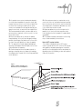
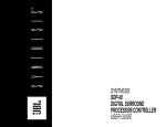
SYNTHESIS
S5160/230
POWER
AMPLIFIER
USER’S
MANUAL
TABLE
OF
CONTENTS
SECTION_______________________________________________________PAGE
1.0
Precautions ________________________________________________________4
1.1
Important Safeguards for Audio Products _______________________________4-7
2.0
Introduction and Features of the S5160 ________________________________8-9
3.0
Operation and Controls ______________________________________________10
3.1
S5160 ________________________________________________________10-12
4.0
Connecting Your Synthesis System ____________________________________13
4.1
JBL Synthesis One – Suggested Rack Mounting Order _____________________14
4.2
JBL Synthesis One – Control Wiring Diagram ____________________________15
4.3
JBL Synthesis One – Interconnection Diagram____________________________16
5.0
Installing the S5160 ________________________________________________17
6.0
Troubleshooting ___________________________________________________18
7.0
Specifications _____________________________________________________19
8.0
Synthesis Limited Warranty __________________________________________20
JBL Synthesis S5160/230 Power Amplifier
User's Manual
©2005 JBL
JBL and Synthesis are registered trademarks of JBL Incorporated.
All Rights Reserved
JBL Synthesis
8500 Balboa Boulevard, Northridge, CA 91329
250 Crossways Park Drive, Woodbury, NY 11797
516.255.4JBL
2, Route de Tours, 72500 Chateau-du-Loir, France
Printed on Recycled Paper
Part Number: S5160/230OM
A Harman International Company
3
1.0
PRECAUTIONS
1.1 Important Safeguards
For Audio Products
PLEASE READ CAREFULLY ALL THE
FOLLOWING IMPORTANT SAFEGUARDS
THAT ARE APPLICABLE TO YOUR EQUIPMENT
CAUTION
RISK OF ELECTRIC SHOCK
DO NOT OPEN
CAUTION: To reduce the risk of electric shock,
do not remove cover (or back).
No user-serviceable parts inside.
Refer servicing to qualified service personnel.
CAUTION: To prevent electric shock,
do not use this (polarized) plug with
an extension cord, receptacle or other outlet
unless the blades can be fully inserted to
prevent blade exposure.
The lightning flash with arrowhead symbol,
within an equilateral triangle, is intended to
alert the user to the presence of uninsulated
“dangerous voltage” within the product’s
enclosure that may be of sufficient magnitude to constitute
a risk of electric shock to persons.
The exclamation point within an equilateral
triangle is intended to alert the user to the
presence of important operating and
maintenance (servicing) instructions in the
literature accompanying the appliance.
1. Read these instructions.
2. Keep these instructions.
3. Heed all warnings.
4. Follow all instructions.
5. Do not use this apparatus near water.
6. Clean only with a dry cloth.
7. Do not block any ventilation openings. Install in accordance with the manufacturer’s instructions.
8. Do not install near any heat sources such as radiators,
heat registers, stoves or other apparatus (including amplifiers) that produce heat.
9. Do not defeat the safety purpose of the polarized or
4
1.0
PRECAUTIONS
grounding-type plug. A polarized plug has two blades with
one wider than the other. A grounding-type plug has two
blades and a third grounding prong. The wide blade or the
third prong are provided for your safety. If the
provided plug does not fit into your outlet, consult an electrician for replacement of the obsolete outlet.
10. Protect the power cord from being
walked on or pinched, particularly at plugs,
convenience receptacles and the point
where they exit from the apparatus.
11. Only use attachments/accessories specified by the
manufacturer.
12. Use only with the cart, stand, tripod, bracket or table
specified by the manufacturer or sold with the apparatus.
When a cart is used, use caution when moving the
cart/apparatus combination to avoid injury from tip-over.
13. Unplug this apparatus during lightning storms or when
unused for long periods of time.
14. Refer all servicing to qualified service personnel.
Servicing is required when the apparatus has been damaged in any way, such as power-supply cord or plug is
damaged, liquid has been spilled
or objects have fallen into the apparatus, the apparatus has
been exposed to rain or moisture, does not operate normally, or has been dropped.
15. Do not use attachments not recommended by the
product manufacturer, as they may cause hazards.
16. This product should be operated only from the type of
power source indicated on the marking label. If you are not
sure of the type of power supply to your home, consult
your product dealer or local power company. For products
intended to operate from battery power, or other sources,
refer to the operating instructions.
17. If an outside antenna or cable system is connected to
the product, be sure the antenna or cable system is
grounded so as to provide some protection against voltage
surges and built-up static charges. Article 810 of the
National Electrical Code, ANSI/NFPA 70, provides information with regard to proper grounding of the mast and supporting structure, grounding of the lead-in wire to an antenna discharge unit, size of grounding conductors, location of
antenna-discharge unit, connection to grounding electrodes, and requirements for the grounding electrode. See
Figure 1.
1.0
PRECAUTIONS
18. An outside antenna system should not be located in
the vicinity of overhead power lines or other electric light
or power circuits, or where it can fall into such power lines
or circuits. When installing an outside antenna system,
extreme care should be taken to keep from touching such
power lines or circuits, as contact with them might be fatal.
19. Do not overload wall outlets, extension cords, or integral convenience receptacles, as this can result in a risk of
fire or electric shock.
20. Never push objects of any kind into this product
through openings, as they may touch dangerous voltage
points or short-out parts that could result in a fire or electric shock. Never spill liquid of any kind on the product.
21. The apparatus shall not be exposed to dripping or
splashing, and no objects filled with liquids, such as vases,
shall be placed on the apparatus.
22. Do not attempt to service this product yourself, as
opening or removing covers may expose you to dangerous voltage or other hazards. Refer all servicing to qualified
service personnel.
23. When replacement parts are required, be sure the
service tech-nician has used replacement parts specified
by the manufacturer or that have the same characteristics
as the original part. Unauthorized substitutions may result
in fire, electric shock or other hazards.
24. Upon completion of any service or repairs to this
product, ask the service technician to perform safety
checks to determine that the product is in proper operating condition.
25. The product should be mounted to a wall or ceiling
only as recommended by the manufacturer.
Note to CATV system installer:
This reminder is provided to call the CATV system
installer’s attention to Article 820-22 of the NEC that provides guidelines for proper grounding and, in particular,
specifies that the cable ground shall be connected to the
grounding system of the building, as close to the point of
cable entry as practical.
Figure 1.
Example of Antenna Grounding as per
National Electrical Code ANSI/NFPA 70
Part No. HCGUL1492/6500 04/2004 EN
5
Deutsch
Wichtige Sicherheitsanweisungen
Español
Instrucciones importantes de sequirdad
Heben Sie sich diese Sicherheitsanweisungen auch für später auf.
Guarde esta instrucciones para uso posterior.
Befolgen Sie alle auf der Vorrichtung stehenden Anweisungen und Warnungen.
Utilice siempre el voltaje correcto. Diríjase a las instrucciones de operación del
fabricante para obtener las especificaciones de potencia. Esté al tanto de que
voltajes de operación distintos requieren el uso de cable y/o enchufes distintos.
Immer nur mit der richtigen Spannung verwenden! Die Gebrauchsanweisungen
des Herstellers informieren Sie über die elektrischen Anforderungen. Vergessen
Sie nicht daß bei vershiedenen Betrievsspannungen ggf. auch verschiedene
Leitungskabel und/oder Verbindungsstacker zu verwenden sind.
Stellen Sie die Vorrightung nicht in ein unbelüftetes Getell oder unmittelbar über
wärmeerzeugende Geräte wie z.B. Tonverstärker. Halten Sie die in den Produktspezifikationen angegebene maximale Umgebungstemperatur bei Betrieb ein.
Schlitze und Öffnungen im GehUause dienen der Belüfung; um verläßlichen
Betrieb sicherzustellen und Überheizen zu vermeiden dürfen diese Öffnungen
nich verstopft oder abgedeckt werden. Stecken Sie nie irgend einen Gegenstand
durch die Belüftungsschlitze. Vergießen Sie keine Flüssigkeiten auf den Apparat.
Dieses Produkt is mit einem 3-drahtigen Erdungsstecher ausgerüstet. Diese
Sicherheitsmaßnahme darf nicht unwirksam gemacht werden.
Schließen Sie nie Tonverstärker unmittelbar an einen Anschluß des Apparates an.
Um elektrischen Schlag oder Feuer zu vermeiden, setaen Sie den Apparat weder Regen
noch Feuchtigkeit aus und betreiben Sie ihn nicht dort wo Wasser eindringen könnte.
Versuchen Sie nicht den Apparat zu betreiben falls er fallen gelassen, beschädigt,
oder Flüssigkeiten ausgesetzt wurde, oder falls sich seine Arbeitsweise derart
ändert daß daraus ein Bedarf nach Raparatur zu schließen ist.
Dieser Apparat sollte nur von qualifizierten Fachleuten geöffnet
werden. Das Abnehmen von Abdeckungen setzt Sie
gefährlichen Spannungen aus.
Dieses Dreick auf ihrem Apparat warnt Sie voe nicht-isolierter,
gefährlicher Spannung im Gehäuse…stark genug um eine
Berührungsgefahr darzustellen.
Diese Dreick auf ihram Apparat bedeutet daß wichtige Betriebsund
Wartungsanweisungen in der mitgelieferten Dokumentation zu
finden sind.
Français
Instructions de Sûreté Importantes
Gardex ces instructions pour réference future.
No instale esta unidad en un estante sin vntilación, ni tampoco directamente
encima de equipose que generen calor tales como amplificadores de potencia.
Fíjese en las temperaturas ambientales máximas de operación que se mencionan
en las especificaciones del producto.
Las aperturas y ranuras del chasis sirven para proveer la ventilación necesaria para
operar la unidad con sequridad y para prevenir sobrecalentamiento, y por lo tanto
no pueden ser obstruidas o cubiertas. No introcuzca objetos de ningún tip a través
de las ranuras de ventilación, y nunca deje caer ningún líquido sobre la unidad.
Este producto está equipado con un enchufe de 3 clavijas con conexión a ierra.
Este es un elemento de seguridad que no debe ser eliminado.
Nunca conecte ningùn tipo de salida de amplificadores de sonido directamente a
los conectores de la unidad.
Para prevenir descargas eléctricas o incendios, mantenga la unidad alejada de la
lluvia, humedad o cualquier lugar en el que pueda entrar en contacto con ague.
No trate de hacer funcionar la unidad si se ha caído, está dañada, ha entrado en
contacto con lítuidos, o si nota cualquir cambio brusco en su funcionamiento
que indique la necesidad de hacerle un servicio de mantenimiento.
Esta unidad deberá ser abierta únicamente por personal calificado. Si usted quita
las coberturas se expondrá a voltajes peligrosos.
Este triángulo que apaece en su componente le advierte sobre la
existencia dentro del chasis de voltajes peligrosos sin aislantes…voltajes que son lo suficientemente grandes como para
causar electrocución.
Este triángulo que aparece en su componente lo alerta sobre las
instrucciones de operación y mantenimiento importantes que
están en los materiales de lectura que se incluyen.
Italiano
Importanti norme di sicurezza
Conservare le presenti norme per l’utilizzo futuro.
Observez toutes les instructions et tous les avertissements marqués sur l’appareil.
Osservare tutte le istruzioni e le avvertenze apposte sull’unita.
Branchez uniguements sur un réseau de tension indiquée. Consultez le manuel
d’instruction du fabriquant pour les spécifications de courant. N’oubliez pas que
différentes tensions peuvent nécessiter l’utilisation de cables et/ou de fiches
deconnexion différents.
Utilizzare esclusivamente con la tensione di rete corretta. Consultare le istruzioni
operative fornite dal fabbricante per i dati riguardanti la tensione e l’assorbimento
di corrente. Potrebbe essere necessario l’uso di cavi di rete e/o di spine diverse a
seconda della tensione utilizzata.
N’installez pas l’appareil en un compartiment non-aéré ou directement au-dessus
d’équipements générateurs de chaleur, tels qu’amplificateurs de courants, etc. Ne
dépassez pas la température ambiante maximale de fonctionnement indiquée
dans les spécifications du produit.
Non installare l’unità in uno scaffale privo di ventilazione oppure direttamente sopra
una fonte di calore, come, ad esempio, un amplificatore. Non superare la temperatura ambientale massima di funzionamento riportata nei dati tecnici del prodotto.
Des fentes et ouvertures sont prévues dans le boîtier pour l’aération; Pour assurer le bon fonctionnement et pour prévenir l’échauffement, ces ouvertures ne
doivent pas être couvertes ou bloquées. N’insérez pas d’objets dans les fentes
d’aération. Empêchez tout liquide de se répandre sur l’appareil.
Le fessure e le altre aperture nella scatola servono alla ventilazione. Per un funzionamento affidabile, e per evitare un eventuale surriscaldamento, queste aperture non vanno ostruite o coperte in nessun modo. Evitare in tutti i casi di inserire
oggetti di qualsiasi genere attraverso le fessure di ventilazione. Non versare mai
del liquido di nessun tipo sull’unità.
Ce produit est muni d’une fiche à trois fils pour la mise à terreee. Ceci est une
mesure de sécurité et ne doit pas être contrariée.
QUesto pordotto viene fornito con una spina a 3 fili con massa. Tale dispositivo
di sicurezza non va leiminato.
Ne connectez jamais d’amplificateurs audio directement aux connecteurs de l’appareil.
Evitare sempre di collegare le uscite dell’amplificatore auio direttamente ai connettori dell’unità.
Pour empêcher les chocs électriques et le danger d’incendie, évitez d’exposer
l’appareil à la pluie ou à l’humidté, et ne le mettez pas en marche en un endroit
où il serait exposé aux éclaboussures d’eau.
N’essayez pas de faire fonctionner l’appareil s’il est tombé à terre, a été endommangé, exposé à un liquide, ou si vous observez des différences nettes dans son
fonctionnement, indiquant la nécessité de réparations.
Cet appareil ne doit être ouvert que par un personnel de service qualifié. En enlevant les couvercles vous vous exposez àdes tensions électriques dangereuses.
Ce triangle, sur votre appaeil vous avertit de la présence de tension dangereuse, non-isolée à l’intérieur du boîtier…une tension
suffisante pour représenter un danger d’electrocution.
Ce triangle sur sur votre appareil vous invite de suivre d’importantes instructions d’utillisation et d’entretien dans la documentation livrée avec le produit.
66
Per prevenire il pericolo di folgorazione e di incendio non esporre l’unità alla
pioggia o ad un’umidtà eccessiva; evitare di adoperare l’unità dove potrebbe
entrare in contatto con acqua.
Evitare di adoperare l’unità se la stessa è stata urtata violentemente, se ha subito
un danno, se è stata esposta ad un liquido o in caso di un evidente cambiamento
dell prestazioni che indichi la necessità di un intervento di assistenza tecnica.
Ogni intervnto sull’unità va esqguito esclusivamente da personale qualificato. La
rimozione della copertura comporta l’esposizione al pericolo di folgorazione.
ll present triangolo impresso sul componente avverte della presenza di tensioni pericolose non isolate all’interno della copertura…tali tensioni rappresentano un pericolo di folgorazione
ll presente triangolo imprsso sul componente avverte l’utente
della presenza nella documentazione allegata di importanti
istruzioni relative al funzionament ed alla manutenzione.
Dansk
Vigtig information om sikkerhed
Suomi
Tärkeitä varten
Gem denne vejledning til senere brug.
Säilytä nämä ohjeet tulevaa käyttoöä varten.
Følg all anvisninger og advaresler på apparatet.
Seuraa kaikkia yksikköön merkittyjä ohjeita ja varoituksia.
Apparatet skal altid tilslttes den korrekte spænding. Der henvises til brugsanvisningen, der indeholder specifikationer for strømforsyning. Der gøres opmærksom på, at ved varierende driftsspændinger kan det blive nødvendigt at bruge
andre lednings- og/eller stiktyper.
Käytä aina oikeaa verkkojännitettä. Tehovaatimukset selviävät valmistajan käyttöohjjeista. Huomaa, että eri käyttöjännitteet saattavat vaatia
toisenlaisen verkkojohdon ja/tai- pistokkeen käytön.
Apparated må ikke monteres i et kabinet uden ventilation eller lige over andet
udstyr, der udvikler varme, f.eks. forstærkere. Den maksimale omgivelsestemperatur ved drift, der står opført i specifikationerne, skal overholdes.
Älä asenna yksikköä telineeseen jossa ei ole tuulet usta, tai välittömästi
lämpöä tuottavien laitteiden, esim. tehovahvistimien, yläpuolelle.
Ympäristön Iämpötila käytössä ei saa ylittää twotespesifikaation maksimilämpötilaa.
Der er ventilationsåbninger i kainettet. For at sikre apparatets drift og hindre
overophidning må disse åbninger ikke blokeres elle tildækkes. Stik aldrig noget
ind igennem ventilationsåbningerne, og pas på aldrig at spilde nogen form for
væske på apparatet.
Kotelo on varustettu tuuletusreiillä ja -aukiooa. Luotettavan toiminnan
varmistamisksi ja ylilämiseksi näitä aukkoja ei saa sulkea tai peittää.
Mitään esineitä ei saa työntää tuuletusaukkoihin. Mitään nestritä ei saa
kaataa yksikköön.
Dette apparat er forsynet med et stik med jordforbindelse. Denne sikkerhedsforanstaltning må aldrig omgås.
Tuote on varustettu 3-jjohtimisella maadoitetulla verkkipistokkeella.
Tämä on turvallisuustoiminne eikä sitä saa poistaa.
Udgangsstik fra audioforstærkere må aldrig sættes direkte i apparartet.
Älä kytke audiotehovahvistimen lähtöjä suoraan mihinkään yksikön liittimeen.
Apparatet må ikke udsættes for regn eller fugt og må ikke bruges i nærheden af
vand for at undgå risiko for elektrisk stød og brand.
Apparatet må aldrig bruges, hvis det er blevet stødt, beskadiget eller vadt, eller
hvis ændringer i ydelsen typer på, at det trænger til eftersyn.
Fette apparat må kun åbnes af fagfolk, Hvis dækslet tages af, udsættes man for
livsfarlig højspænding.
Denne mærkat på komponenten advarer om uisoleret, farlig
spænding i apparatet… høj nok til at give elektrisk stød.
Denne mærkat på komponenten advarer om vigtig driftsog
vedligeholdsinformation i den tilhørende litteratur.
Sähköiskun ja palovaaran välttämiseksi yksikkö ei saa olla sateessa tai
kosteassa, eikä sitä saa käyttää märässä ympäristössa.
Älä käytä yksikköä jos se on pudonnut, vaurioitunut, kostunut, tai jos
sen suorituskkyky on huomattavasti muuttunut, maikä vaatii huoltoa.
Yksikön saa avata vain laitteeseen perehtynyt huoltohenkilö. Kansien
poisto altistaa sinut vaarallisille jännittelille.
Tämä kolmio, joka esiintyy homponentissasi, varoittaa
siua eristämättömän vaarallisen jännitteen esiintymisestä
yksikön sisällä. Tämä jännite saattaa olla riittävä korkea
aiheuttamaan sähköiskuvaaran.
Tämä koimio, joka esiintyy komponentissasi, kertoo sinulle, että tässä tuotedokumentoinnissa esiintyy tärkeitä
käyttö-ja ylläpite-ohjeita.
Norsk
Viktig informasjon om sikkerhet
Svenska
Viktiga säkerhetsföreskrifter
Ta vare pådenne veiledningen for senere bruk.
Spara dess föreskrifter för framtida bruk.
Følg alle anvisningene og advarslene som er angitt på apparatet.
Följ alla anvisningar och varningar som anges på engeten.
Apparatet skal alltid anvendes med korrekt spenning.
Använd alltid rätt nätspänning. Se tillverkarens bruksanvisningar för information om effektkrav. Märkväl, att andra matningsspänningar eventuellt kräver att
en annan typs nätsladd och/eller kontakt anänds.
Produktbeskrivelsen inneholder spesifikasjoner for strømkraav. Vær oppmerksom
på at det ved ulike driftsspenninger kan være nødvendig å bruke en annen ledningog/eller støpseltype.
Apparatet skai ikke monteres i skap uten ventilasjon, eller direkte over varmeproduserende utstyr, som for eksempel kraftforsterkere. Den maksimale romtemperaturen som står oppgitt i produktbeskrivelsen, skal overholdes.
Apparatet er utstyrt med ventilasjonsåpninger. For at apparatet skal være pålitelig
i bruk og ikke overopphetes, må disse åpningene ikke blikkeres eller tildekkes.
Stikk aldri noe inn i ventilasjonsåpningene, og pass på at det aldri søles noen
form for væske på apparatet.
Dette apparatet er utstyrt med et jordet støpsel. Dette er en sikkerhetsforanstaltning som ikke må forandres.
Utgangsplugger fra audioforsterkere skai aldri koples direkte til apparatet.
Unngå brannfare og elektrisk støt ved å sørge for at apparatet ikke utsettes for
regn eller fuktighet og ikke anvendes i næheten an vann.
Apparatet skal ikke brukes hvis det har blitt utsatt for støt, er skadet eller blitt vått,
eller hvis endringer i ytelsen tyder på at det trenger service.
Dette apparatet skal kun åpnes av fagfolk. Hvis dekselet fjernes, utsettes man for
livsfarlig høyspenning.
Komponenten er merket med denne trekanten, som er en
advarsel om at det finnes uisolert, farlig spenning inne i kabinettet…høy nok til å utgjøre en fare for elektrisk støt.
Komponenten er merket med denne trkanten, som betyr at den
tilhørende litteraturen inneholder viktige opplysninger om drift
og vedikehold.
Installera inte enheten i ett oventilerat stativ, eller direkt ovanför utrustningar
som avger värme, t ex effektförstärkare. Se till att omgivningens temperatur
vid drift inte överskrider det angivna värdet i produktspecifikationen.
Behållaren är försedd med hål och öppningar för ventilering. För att garantera
tillförlitlig funktion och förhindra överhettning får dessa oppningar inte blockeras eller täckas. Inga föremål får skuffas in genom ventilationshålen. Inga
vätskor får spillas på enheten.
Produkten är försedd med en jordad 3-trådskontakt. Detta ä en säkerhetsfunktion som inte får tas ur bruk.
Anslut aldrig audioeffektförstärkarutgångar direkt till någon av enhetens
kontakter.
För att undvika elstöt eller brandfara får eenheten inte utsättas för reegn eller
fukt, eller användas på ställen där den blir våt.
Använd inte enheten om den far fallit i golbet, skadats, blivit våt, eller om dess
prestanda förändrats märkbart, vilket kräver service.
Enheten får öppnas endast av behörig servicepersonal. Farliga spänningar blir
tillgängliga när locken tas bort.
Denna triangel, som visas på din komponent, varnar dig om
en oisolerad farlig spänning inne i engeten. Denna spänning
är eventuellt så hög att fara för elstöt föreligger.
Denna triangel, som visas på din komponent, anger att viktiga
bruksanvisningar och servideanvisningar ingår i dokumentationen i fråga.
77
2.0
INTRODUCTION
AND FEATURES
Introduction
Congratulations on your purchase of this JBL Synthesis
S5160 power amplifier! You have purchased a product
that embodies the best of what JBL has learned about the
emotional power of audio reproduction in over fifty years
of preeminence in the field. This amplifier has been
designed and crafted to provide the user with a high level
of sonic performance; special attention has been paid to
minimize the number of components in the audio signal
path, resulting in extremely low distortion, excellent transient response, and wide dynamic range. Synthesis products set new benchmarks in audio technology, and, when
used as part of a complete JBL Synthesis System, will
bring the ambience and acoustics of some of the world’s
greatest concert halls and theaters into your home.
To obtain the best performance from this amplifier, please be
sure to completely read this user’s manual and use the
S5160 only in accordance with its instructions.
Features
The JBL Synthesis S5160 power amplifier features the
following:
®
THX Ultra Specifications
This amplifier meets or exceeds the stringent specifications set by
the THX Ltd. Audio division in their specifications for "Ultra"-class
certification, including power handling, total harmonic distortion,
frequency response, signal to noise ratio, slew rate, and crosstalk.
When incorporated into a complete THX system, you will hear in
your home what the director and sound engineer heard in the
recording studio.
Full Five Channel Operation
The S5160 has been designed to integrate well into the
world of multi-channel audio. It is designed to reproduce
the front left and right, center and side channels, to produce a truly enveloping sound field. When coupled with a
high quality subwoofer amplifier, such as the Synthesis
S800, it is a solid foundation on which to build a highperformance home cinema system that will astound the
listener with its power and realism. The S5160 is specially
designed for use with a Synthesis One system in which
the front left, right and center speakers are bi-amplified for
smoother and more accurate reproduction of every
8
2.0
INTRODUCTION
AND FEATURES
nuance of a movie soundtrack or musical selection. Two
S5160 amplifiers may be used, in conjunction with 2
S800 subwoofer amplifiers, to power a complete 7.1channel home theater system. Alternatively, a single
S5160 may be used with one S800 subwoofer amplifier
to power a 5.1-channel system.
High Power Capability
The S5160 provides a satisfying 160 watts per channel of
distortion-free audio (<0.03% THD) into eight ohms.
Because of their power capabilities, all Synthesis amplifiers
have an extremely wide dynamic range, an element critical
to realistic home cinema. Sound levels equal to those at
original performances are easily recreated in even the largest
of home listening environments.
Auto Turn-On and Power Sequencing Circuitry
When used in a JBL Synthesis System, the S5160 can
be turned on automatically whenever the surround processor is activated. No longer do you have to get out of that
chair to turn on the various pieces of equipment in your
entertainment system; just one touch on the remote control of the surround processor, and you’re a few seconds
away from a truly impressive audio presentation!
Modern amplifiers produce more power per channel (and
frequently have more channels) than those of the traditional two-channel stereo era. Due to the high current
demands of power amplifiers at the instant of turn-on, the
S5160, S7150, and S800 amplifiers and the SDEC digital equalizer are equipped with power sequencing circuits
which turn on each unit in sequence, avoiding the large
instantaneous current demand (and possible house circuit
breaker tripping) that would occur should they all turn on
at the same instant.
2.0
INTRODUCTION
AND FEATURES
Quiet Cooling
The S5160 utilizes a fan to cool the amplifier channels,
ensuring long-term reliability. To reduce fan noise to an
absolute minimum, a thermal sensing and control circuit
has been incorporated in the Synthesis S5160 that senses increases in temperature within the amplifier and powers a fan at a speed proportional to that temperature
increase. When the S5160 is used at lower volume levels,
the fan turns very slowly – and quietly. At high listening
levels (and the higher operating temperatures this creates
within any amplifier), the sensing circuitry causes the fan
to turn faster, producing increased cooling. As a result, the
fan is never turning faster than necessary, and most of the
noise that is generated is masked by the program being
listened to.
2.0
INTRODUCTION
AND FEATURES
power demand, and turns the affected channel(s) and their
blue front panel indicators off until the fault condition is
removed, at which time normal operation is automatically
restored. While protection of this sort is not uncommon in
today’s well-designed amplifiers, a remarkable feature of
the Synthesis S5160’s protective circuits is that they are
optically-coupled to the signal circuit; there is no direct
electrical connection between the signal path and the protective circuitry.
As a result, there can be no coloration of the
music, no interaction between protection and
amplification, until certain thresholds are
exceeded, at which point the channel(s) turn off
completely.
Comprehensive and Isolated Circuit Protection
The S5160 amplifier employs a sophisticated protective
circuit (one for each channel) that senses many possible fault
conditions, such as shorted loudspeaker wires or excess
9
3.0
3.0
OPERATION AND CONTROLS
3.1 S5160
1. Power Switch
Pushing this button is all that is required to turn on the
S5160 if it is not part of a Synthesis system and the
Manual On/Auto On switch ¶ (rear panel) is in the
Manual On position. If the amplifier is used as part of a
JBL Synthesis System, and the Manual On/Auto On
switch ¶ is in the Auto On position, the amplifier will
turn on when the surround processor is activated. The
front panel pushbutton power switch is left in the ON (in)
position. See the description of the Manual On/Auto
On switch ¶ for more information on turning on the
S5160.
2. Standby Indicator (red)
This indicator, immediately above the front panel power
switch, will glow red when the amplifier is in the "standby"
mode, whether operating as part of a Synthesis system or
not. When the S5160 is in the "operate" mode, this light
will shut off and the blue "operate" mode indicators will
light..
3. Power Indicators (blue)
These indicators will light up when the power amplifier is in
the "operate" mode. Each monitors the operation of one
channel, and will extinguish if that channel’s protective circuit is activated.
10
OPERATION AND
CONTROLS
4. Input Jacks (Ch.1 thru Ch.5)
The output signals from the Synthesis digital processor and
equalizer are connected to the input jacks in a Synthesis
one System. We suggest the channels be assigned as follows:
Amplifier #1:
Channel 1
Channel 2
Channel 3
Channel 4
Channel 5
Center Low-Frequency
Center High-Frequency
Right Front Low-Frequency
Right Front High-Frequency
Right Rear Surround
Amplifier #2:
Channel 1
Channel 2
Channel 3
Channel 4
Channel 5
Right Side Surround
Left Side Surround
Left Front Low-Frequency
Left Front High-Frequency
Left Rear Surround
3.0
OPERATION AND
CONTROLS
¢
ª
•
¶
§
‚
∞
S5160/230
5. Speaker Terminals
6. External Fusess
Connect the speakers to these terminals, following the normal convention; wire the "+" side of the speaker to the red
terminal, and the "–" side to the black terminal. Wire the
speakers with the proper polarity; reversing any speaker’s
connections will not damage either the speaker or the
amplifier, but will result in poor low frequency performance
and imprecise imaging.
AC mains fuses are located on the back panel of the
amplifier. These fuses will not blow unless the amplifier is
asked to produce more power than its design allows for a
prolonged period or to prevent excessive current drawn
that could damage internal components during a fault condition.
WARNING: Terminals marked with the flash symbol are
hazardous when live. External wiring connected to those
terminals requires installation by trained personnel, and the
use of ready-made lead cords.
NOTE: The minimum load impedance that this amplifier
can handle safely is eight ohms per channel. Using lower
impedance loads can damage the unit and will void your
warranty!
Wire Run
RunLength
Length
Wire
Rec. Ga.
Minimum
Gauge
Up to 20'
16
Up to 50'
14
Up to 100'
12
The amplifier has been designed to operate under virtually
all conditions. Even momentary short circuiting of the output (speaker) connections will not ordinarily damage the
output circuitry (although this will activate internal protective
circuitry and cause one or more of the front panel LED
indicators to extinguish until the circuit resets.)
Fuse Replacement
To remove the fuse, turn off the power switch and disconnect the power plug from the AC mains. Unscrew the fuse
holder cap and remove the fuse, install the new fuse and
secure the holder cap and reconnect the AC mains. If after
replacing the fuse the unit is inoperative, service is
required; contact your JBL Synthesis dealer.
WARNING: Always unplug the amplifier from
the AC mains before removing any fuse.
IMPORTANT: Never install a fuse that has a
higher rating than that specified on the
back panel of the amplifier or in the owners
manual.
11
3.0
OPERATION AND CONTROLS
7. Auto On/ Manual On Switch
Put this switch in the Auto On position if the amplifier is
being used as part of a JBL Synthesis System. When
used in this way, the S5160 will automatically turn on
when the power switch is depressed and the surround
processor is activated. For other installations, or should
individual control of each component be desired, put this
switch in the Manual On position. The amplifier will then
be controlled solely by the front panel switch.
8. IN/OUT DIN Jacks
If you are using the amplifier as part of a JBL Synthesis
System, it is necessary to use these jacks to interconnect to
other system components, so that control signals (power
on/off and music/cinema mode switching) can be transmitted from one unit to the next, starting at the surround
processor, through the equalizer and amplifiers, and ending
at the speakers. Follow the connection diagrams on the
following pages for detailed information regarding these
connections. Make connections to these jacks only as
shown in the diagrams. If these jacks are used in any
other manner, e.g., to control electric screens, the unit can
be damaged and the warranty will be void. For specific electrical information on these jacks, contact JBL Synthesis
Customer Service.
Do not plug anything into these jacks if you
are not using the S5160 with a JBL Synthesis
System.
12
3.0
OPERATION AND
CONTROLS
9. Speaker Mode Control Connectors
The front left and front right speakers are switched
between Music and Cinema modes by signals present at
both the DIN connectors (as described in the previous
paragraph) AND the 2-conductor connectors shown at ª.
The installer may find it preferable to use 2-conductor wire
(18 gauge recommended) rather than long multi-conductor DIN cables for the mode-switching connection between
the S5160 and these two speakers. Adapters supplied
with the S5160 are used at the speaker end of the wire to
allow connection to the speakers' DIN input connectors.
Proper polarity must be observed as shown in the wiring
diagrams; reverse the connections at one end of the wire
if the speaker(s) do not switch modes (from horn (Cinema)
to tweeter (Music)).
Note that 5-conductor DIN cables MUST be used between
all other components to allow correct power and mode
switching and that the same warning not to plug anything
into these jacks, if you are not using the S5160 with a
JBL Synthesis System applies here; do not attempt to use
these jacks to control anything other than the modeswitching function of Synthesis speakers, as this may damage the S5160 and will void the warranty.
10. AC Inlet
Your S5160 is shipped with an IEC-type removable power
cord that mates with the AC inlet on the rear panel. To
ensure proper operation, use the supplied power cord.
This amplifier is NOT a multi-voltage unit; using a
power cord that is not compatible with a 230V, 50Hz AC
wall receptacle will void the warranty.
4.0
INTERCONNECTIONS IN
SYNTHESIS SYSTEMS
4.0
CONNECTING YOUR
SYNTHESIS SYSTEM
General Information
A Synthesis One installation utilizing the benefits of bi-amplification of the front speakers incorporates a total of 4 power
amplifiers; 2 S5160s, and 2 S800’s. Eight of the ten channels on the S5160s are to be used for driving the HI frequency and LO frequency inputs on the left, center, and right
speakers, as well as the two side ambient speakers, as indicated in the charts on page 8. Please refer to the connection
chart on the following page.
Use the simplified connection diagrams on the following
pages to help you understand how to connect the S5160
amplifier to a JBL Synthesis System. These diagrams are
intended to show the signal flow through the system. For
more detail in making these connections, please refer to the
JBL Synthesis Certified Dealer Installation Manual.
Connect DIN and audio cables between system components, as
shown on the following pages. Make sure that on all power
amplifiers the power switches are in the depressed (ON)
position and that the Auto On/ Manual On switches ¶
are in the Auto On position. Operated in this mode, all of
the components will turn on with one touch of the power button on the surround processor's remote control.
13
4.1 Synthesis One
Suggested Rack Mounting Order
SDP-40
SDEC-1000A
4.0
CONNECTING YOUR
SYNTHESIS SYSTEM
Top
#1
#2
#3
S800/230
#4
S5160/230
14
4.0
CONNECTINGYOUR
YOUR
CONNECTING
SYNTHESISSYSTEM
SYSTEM
SYNTHESIS
4.2Synthesis
SynthesisTwo
One& Three
4.2
ControlWiring
WiringDiagram
Diagram
Control
2
3
INPUTS
4
INPUT 1
5
Y
VIDEO
1
PR
COMPONENT VIDEO
INPUT 2
PB
Y
PR
Y
PR
PB
Y
S-VIDEO
MAIN OUTPUTS
INPUT 3
PR
INPUT 4
Y
PR
2
1 (OSD)
1
AUDIO
2
3
4
5
6
7
FRONT
CENTER
SIDE
SUBWOOFER
REAR
L
(L)
L
(C)
(LS)
L
L
L
L
R
(R)
R
(SUB)
(RS)
R
R
R
R
2
3
4
5
6
S/PDIF
1
2
LFE
MICROPHONE INPUTS
3
1
2
3
VIDEO
Fix
Fix ZONE 2 Var
AUX
L
R
1
AES/EBU
8
2
PB
VIDEO
1
SPEAKERCON
TROL JACK
RECORD OUTPUTS
PB
OUTPUT
PB
1
AUDIO
MAIN AUDIO OUTPUTS
Var
S/PDIF
4
5
1
6
2
IR IN
MAIN
AUDIO
OUTPUTS
RS 232
SDP-40
L
FRONT
CENTER
R
DIN IN
WARNING – To reduce the risk of
fire or electric shock, do not expose
this appliance to rain or moisture.
Do not remove cover. No user
serviceable parts inside. Refer
servicing to qualified service personnel.
R-AMB
L-AMB
R-SUB
LFE
L SUBWOOFER R
L
SIDE
R
REAR
R
L
AUX
R
L
ZONE 2
R
CONTROL JAC
K SIGNALS
SDEC-1000A
Digital Equalizer Controller
JBL Inc., Northridge CA
Made in USA
RS-232
DIN OUT
L
®
CINEMA
MODE
AUTO
MODE
AUTO
ON
MANUAL
ON
THX CONNECTOR
ANALOG INPUT
OUTPUT
L-SUB
SDEC-2500A/230
CINE
MA
MODE
C-LO
C-HI
R-LO
L-LO
AUTO
MODE
R-HI
L-HI
R-IN
AUTO
ON
L - IN
SUB-IN
C-IN
(UseCine
" maode"
M position
on
ly
whenhere
t arenomusic de
mo
speakersin ethyste
s m.)
Manu
al
On
S5160/230
R-AMB-IN
MANUAL
ON
PIN1
PIN2
PIN3
PIN4
PIN5
L-AMB-IN
Manu
al
On
Auto
On
VOIR EL CA
HIER D'
INSTRUCTI
ON
reduc
e the
risk offireor
WARNING; To
electr
ic shock
, do tno
xepose
S800 POWER AMPLIFIER
e to
ain
or
r oistur
me
this applianc
2
4
TO SPEAKERS
Ch. 1
BRIDGED
Input
JBL SYNTHESIS
NORTHRIDGE, CA
BRIDGED
MONO
Ch. 2
Input
STEREO
DESIGNED, ENGINEERED ANDMANUFACT
URED
INTHE UNITED STATES OF AMERICA
E TRIQUE NEPASOUVRIR
AVIS: RISQUE DE CHOC LEC
WARNING:
HAZARDOUS ENERGY, MAKEPROPER SPEAKER
CONNECTI
ONS; SEE OWNERS MANUAL BEFORE USING.
ATTENTION:
F1
T4AL,250VAC
Stere
o/Mon
o Man
ual
On
Mini
mum
4 Ohm
s Ste
reo
Mini
mum
4 Ohm
s Ste
reo
VOIR EL CA
HIER D'
INSTRUCTI
ON
reduc
e the
risk offireor
WARNING; To
electr
ic shock
, do tno
xepose
S800 POWER AMPLIFIER
this applianc
e to
ain
or
r oistur
me
Ch. 1
BRIDGED
Input
JBL SYNTHESIS
NORTHRIDGE, CA
BRIDGED
MONO
STEREO
Ch. 2
Input
Auto
On
DESIGNED, ENGINEERED ANDMANUFACT
URED
INTHE UNITED STATES OF AMERICA
No user
ser
vicea
ble par
ts inside.
Refer
servicin
g toquali
fied per
sonn
el.
E TRIQUE NEPASOUVRIR
AVIS: RISQUE DE CHOC LEC
HAZARDOUS ENERGY, MAKEPROPER SPEAKER
serialnumber
S800/230
T4AL,250VAC
230V~50/60Hz 2400W
IN
TRIGGERS
MANUAL
ON
CAUT
ION
RISK OF ELECTRICSHOCK
DO NOT OPEN
WARNING:
CONNECTI
ONS; SEE OWNERS MANUAL BEFORE USING.
F1
Stere
o/Mon
o Man
ual
On
Mini
mum
4 Ohm
s Ste
reo
WARNING:
HAZARDOUS ENERGY, MAKE PROPER SPEAKER
CONNECTI
ONS. SEE OWNERS MANUAL BEFORE USING
15
15
OUT
AUTO
ON
T4AL,250VAC
F2
Minimu
m8 Ohms
Bridge
Mini
mum
4 Ohm
s Ste
reo
OUT
AUTO
ON
F2
Minimu
m8 Ohms
Bridge
WARNING:
HAZARDOUS ENERGY, MAKE PROPER SPEAKER
CONNECTI
ONS. SEE OWNERS MANUAL BEFORE USING
S800/230
IN
TRIGGERS
MANUAL
ON
CAUT
ION
RISK OF ELECTRICSHOCK
DO NOT OPEN
1) To ensure proper operation, connect the system control lines
exactly as indicated.
2) If any of the control lines become disconnected while the
system is on, turn off all Synthesis components before
reconnecting control lines. This will reset all operation.
1
Ground
Ground
+5vdc whenPowerison
NotUsed
+5vdc n
i iC
ne
ma
mode
5
No user
ser
vicea
ble par
ts inside.
Refer
servicin
g toquali
fied per
sonn
el.
serialnumber
NOTES
3
Auto
On
ATTENTION:
S5160/230
2
PIN1 Ground
PIN2 +5vdc n
i iC
ne
ma
mode
AUDIO
TRIGGER OUTPUTS
4
Auto
On
T4AL,250VAC
230V~50/60Hz 2400W
4.0
CONNECTING YOUR
CONNECTING
YOUR
SYNTHESIS
SYSTEM
SYNTHESIS SYSTEM
4.3
4.3 Synthesis
Synthesis Two
One & Three
Interconnection
Interconnection Diagram
Diagram
2
3
INPUTS
4
INPUT 1
5
Y
VIDEO
1
INPUT 2
PR
PB
Y
PR
Y
PR
COMPONENT VIDEO
Y
PB
S-VIDEO
MAIN OUTPUTS
INPUT 3
PR
INPUT 4
Y
PR
2
1 (OSD)
1
2
3
4
AUDIO
6
1
8
(LS)
(C)
(R)
R
(RS)
(SUB)
FRONT
CENTER
R
1
2
3
4
5
6
LFE
MICROPHONE INPUTS
1
3
2
SIDE
SUBWOOFER
L
REAR
L
5
1 to6 RCA
-RCA 2.5 mete
r Surround
Processor
toSDEC2500A
7 to11 RCA
-Rt.RCA 2.0 mete
r SDEC2500Ato
S7150/230, Rtangle
RCA
attac
hestoAmp
side
12 & 13 RCA
-RCA 2.0 mete
r SDEC2500AtoS800
Amp
s
14 & 15 RCA
-Rt.RCA 2.5 mete
r Surround
Processorto
S7150/230 rear
ambi
ent
chann
elsforusein
7.1 systems
#
R
R
VIDEO
Fix
Fix ZONE 2 Var
AUX
L
Var
L
R
AUDIO
MAIN AUDIO OUTPUTS
AUDIO
TRIGGER OUTPUTS
4
3
S/PDIF
2
4
7
(L)
L
R
R
AES/EBU
5
L
L
2
PB
VIDEO
1
Cables Included in S2500IC
RECORD OUTPUTS
PB
OUTPUT
PB
S/PDIF
1
2
IR IN
6
MAIN
AUDIO
OUTPUTS
RS 232
L
FRONT
CENTER
R
LFE
L SUBWOOFER R
L
SIDE
L
R
REAR
R
L
AUX
R
ZONE 2
L
R
SDP-40
type
length
useage
SDEC-1000A/230
DIN IN
SDEC-1000A
Digital Equalizer Controller
JBL Inc., Northridge CA
Made in USA
RS-232
DIN OUT
WARNING – To reduce the risk of
fire or electric shock, do not expose
this appliance to rain or moisture.
Do not remove cover. No user
serviceable parts inside. Refer
servicing to qualified service personnel.
R-AMB
L-AMB
R-SUB
®
CINEMA
MODE
AUTO
MODE
AUTO
ON
MANUAL
ON
THX CONNECTOR
ANALOG INPUT
OUTPUT
L-SUB
C-LO
C-HI
R-LO
L-LO
R-HI
L-HI
R-IN
L-IN
SUB-IN
C-IN
R-AMB-IN
L-AMB-IN
ATTENTION:
VOIR LE CAHIE
R D'
INSTRUCTION
Tore
ducetherisk offirero
WARNING; ele
ctricshock, donot
exp
ose
S800 POWER AMPLIFIER
thisapp
liance
torai
n or
mo
isture
Ch. 1
BRIDGED
Input
JBL SYNTHESI
S
NORTHRIDGE, C
A
BRIDGED
MONO
Ch. 2
Input
STEREO
DESIGNED, ENGINEERED ANDMANUFACTUR
ED
INTHEUNITED STATES OFAMERICA
OUT
TO
MANUAL AU
ON
ON
No user
servic
eabl
e pa
rtsinsid
e.Refer
servicingtoqualified rsonn
peel.
Manual
On
S7150/230
Auto
On
CAUTION
RISK OF ELECTRICSHOCK
DO NOT OPEN
OCELECTRIQ
UE NEPAS OUVRIR
AVIS: RISQUE DE CH
ENERGY, MAKEPROPER SPEAKER
WARNING: HAZARDOUS
CONNEC
TIONS; SEE OWNERS MANUAL BEFORE USING.
T4AL, 250VAC
F2
ual
Stereo
/Mono Man
On
m
Minimu
4 OhmsStereo
WARNING:
HAZ
ARDOUS ENERGY, MAKE PROPER SPEAKER
CONNECT
IONS. SEE OWNERS MANUAL BEFORE USING
S800/230
ATTENTION:
F1
Minimu
m Ohms
8
Bridge
Minimu
m
4 OhmsStereo
serialmber
nu
VOIR LE CAHIE
R D'
INSTRUCTION
Tore
ducetherisk offirero
WARNING; ele
ctricshock, donot
exp
ose
S800 POWER AMPLIFIER
thisapp
liance
torai
n or
mo
isture
Ch. 1
BRIDGED
Input
JBL SYNTHESI
S
NORTHRIDGE, C
A
BRIDGED
MONO
STEREO
Ch. 2
Input
Auto
On
DESIGNED, ENGINEERED ANDMANUFACTUR
ED
INTHEUNITED STATES OFAMERICA
CAUTION
RISK OF ELECTRICSHOCK
DO NOT OPEN
ENERGY, MAKEPROPER SPEAKER
WARNING: HAZARDOUS
serialmber
nu
S800/230
16
16
T4AL, 250VAC
230V~50/60Hz 2400W
IN
TRIGGERS
OUT
TO
MANUAL AU
ON
ON
No user
servic
eabl
e pa
rtsinsid
e.Refer
servicingtoqualified rsonn
peel.
OCELECTRIQ
UE NEPAS OUVRIR
AVIS: RISQUE DE CH
S7150/230
IN
TRIGGERS
CONNEC
TIONS; SEE OWNERS MANUAL BEFORE USING.
F1
T4AL, 250VAC
F2
Minimu
m Ohms
8
Bridge
ual
Stereo
/Mono Man
On
Minimu
m
4 OhmsStereo
Minimu
m
4 OhmsStereo
WARNING:
HAZ
ARDOUS ENERGY, MAKE PROPER SPEAKER
CONNECT
IONS. SEE OWNERS MANUAL BEFORE USING
Auto
On
T4AL, 250VAC
230V~50/60Hz 2400W
5.0
PHYSICAL
CONSIDERATIONS
5.0
INSTALLING YOUR
POWER AMPLIFIER
Installation of the S5160 is a straightforward process.
IMPORTANT: Amplifier must be installed following
the directions described below, to insure adequate
performance and safety never install the
amplifier with less free spacing around the
amplifier than the specified.
1. The Synthesis S5160 power amplifier has been
designed to be mounted in EIA standard racks or stacked
freestanding as long as there are four inches (10cm) of
free spacing around the amplifier (Top, sides and rear) If
the S5160 is being mounted in a rack, it is suggested that
its feet be removed prior to installation. If the S5160 will
be stacked with other components, use the feet that came
attached to the unit. This will ensure that there is sufficient
air space underneath so that heat can be dissipated effectively.
2. Make sure that the amplifiers are located in a well-ventilated, cool area. Be certain that the front and rear panels
are not obstructed, as the cooling fan brings air in from the
front and expels it at the rear. It is very important not to
obstruct the airflow from the center front panel; heat
buildup and premature failure may occur.
17
6.0
6.0
TROUBLESHOOTING
TROUBLESHOOTING
Problem: Amplifier does not turn on. Neither the red nor blue
indicator lights are on.
Make sure that the amplifier is plugged in, and verify that there is
the proper voltage (230V) at the wall outlet.
Problem: The red indicator lights, but the blue indicators do not
light up when the power switch is depressed.
1. If the amplifier is being used in a Synthesis system, make sure
that the surround processor is turned on, the Auto On/Manual
On switch is in the Auto On position, and that all of the necessary DIN cables are connected between the various system
components. Refer to the "CONNECTING YOUR SYNTHESIS
SYSTEM" section for reference.
2. If the amplifier is not being used with a Synthesis system, make
sure that the Auto On/Manual On switch is in the Manual On
position.
Problem: There is no sound from the speakers, but the
er is on (blue indicators lit).
amplifi-
1. Make sure that the surround processor or equalizer is on, and
that the correct source has been connected and selected.
2. Make sure that the correct outputs are connected from the
surround processor or equalizer to the amplifier.
3. Make sure that the speakers are connected to the correct terminals. Check for short circuits at both ends of the speaker
cables.
Problem: Not all of the amplifiers turn on in a Synthesis system.
1. Make sure that all required DIN cables are connected between
system components. Refer to the "CONNECTING YOUR SYNTHESIS SYSTEM" section.
2. Make sure that each amplifier has its Auto On/Manual On switch
in the Auto On position.
18
Problem: Insufficient audio from the speakers.
Check that the output levels of the surround processor or
equalizer are set properly.
Problem: Insufficient bass.
Verify that the speakers have been wired to the amplifier with
the correct polarity.
Problem: Front speakers do not switch from music to cinema
mode.
1. Make sure that the screw terminal and DIN adapter cables to
speakers are correctly wired and are connected to the correct
jacks on the S5160.
2. Make sure that all required DIN cables are connected between
system components.
Problem: Audible hum from the speakers.
1. Check the power outlets and make sure that there is a solid
earth ground present. (The services of an electrician may be
required.)
2. Make sure that all signal cables are routed away from power
cords.
3. If these suggestions fail, experiment by running ground wires
between the rear panel screws of the amplifiers and the other
system components, such as the surround processor or signal
processing package.
If you still encounter difficulty after trying the above suggestions, call
your JBL Authorized Dealer or visit our website at www.jbl.com for
further assistance.
7.0
7.0
SPECIFICATIONS
SPECIFICATIONS
Rated Power Output
160W per channel into 8 ohms, all channels driven
THD
< 0.03% 20Hz - 20kHz
Input Impedance
28k ohms
Sensitivity
1V in = 28.28V out (THX Level)
1.25V in = 150 watts out
Frequency Response ( at 1 W )
S/N Ratio ( A-weighted at rated power )
20Hz – 20kHz
≥ 100dB
Damping Factor ( 8 ohms )
≥≥ 400
Dynamic Headroom
5Hz – 100kHz
+ 0, – 0.25dB
+ 0, – 3dB
IM Distortion
≤ 0.03%
Unit Size
178 mm (H) x 484 mm (W) x 495 mm (D) – 7” H x 19” W x 19¹⁄₂” D
Unit Weight
44 kg – 97 Ibs
Shipping Weight
50 kg – 111 Ibs
All features and specifications are subject to change without notice.
THX is a trademark of THX Ltd.
19
JBL Synthesis
8500 Balboa Boulevard
Northridge, CA 91329
250 Crossways Park Drive
Woodbury, NY 11797
800-336-4JBL
Chateau-du-Loir, France
Part No. S5160/230 OM
Printed in USA on recycled paper