1
T-8420A, 8421A, 8422A
T-8720A, 8722A
SERVICE MANUAL
Please read this manual before making any adjustments.
TWIN NEEDLE LOCK STITCHER
This service manual is intended for T-8420A, 8421A, 8422A, 8720A, 8722A; be sure to read the instruction manual before this
manual.
Carefully read the “SAFETY INSTRUCTIONS” below and the whole of this manual to understand this product before you start
maintenance.
As a result of research and improvements regarding this product, some details of this manual may not be the same as those for
the product you purchased.
If you have any questions regarding this product, please contact a Brother dealer.
SAFETY INSTRUCTIONS
1. Safety indications and their meanings
This service manual and the indications and symbols that are used on the machine itself are provided in order to ensure safe
operation of this machine and to prevent accidents and injury to yourself or other people.
Indications
DANGER
The instructions which follow this term indicate situations where failure to follow the
instructions will almost certainly result in death or severe injury.
CAUTION
The instructions which follow this term indicate situations where failure to follow the
instructions could cause injury when using the machine or physical damage to equipment
and surroundings.
Symbols
·····
This symbol (
) indicates something that you should be careful of. The picture inside the triangle
indicates the nature of the caution that must be taken.
(For example, the symbol at left means “beware of injury”.)
·····
This symbol (
·····
This symbol (
) indicates something that you must do. The picture inside the circle indicates the
nature of the thing that must be done.
(For example, the symbol at left means “you must make the ground connection”.)
) indicates something that you must not do.
T-8400A, 8700A
i
2. Notes on safety
DANGER
Wait at least 5 minutes after turning off the power switch and disconnecting the power cord from the wall outlet before
opening the face plate of the control box. Touching areas where high voltages are present can result in severe injury.
CAUTION
Environmental requirements
Use the sewing machine in an area which is free
from sources of strong electrical noise such as
high-frequency welders.
Sources of strong electrical noise may cause
problems with correct operation.
Any fluctuations in the power supply voltage should
be within ±10% of the rated voltage for the machine.
Voltage fluctuations which are greater than this may
cause problems with correct operation.
The power supply capacity should be greater than
the requirements for the sewing machine's
electrical consumption.
Insufficient power supply capacity may cause
problems with correct operation.
The relative humidity should be within the range of
45% to 85% during use, and no dew formation
should occur in any devices.
Excessively dry or humid environments and dew
formation may cause problems with correct
operation.
Avoid exposure to direct sunlight during use.
Exposure to direct sunlight may cause problems with
correct operation.
In the event of an electrical storm, turn off the power
and disconnect the power cord from the wall outlet.
Lightning may cause problems with correct
operation.
The ambient temperature should be within the
range of 5°C to 35°C during use.
Temperatures which are lower or higher than this
may cause problems with correct operation.
Installation
Machine installation should only be carried out by a
qualified technician.
Contact your Brother dealer or a qualified
electrician for any electrical work that may need to
be done.
The sewing machine weighs approximately 50 kg.
The installation should be carried out by two or
more people.
Do not connent the power cord until installation is
complete. The machine may operate if the treadle is
depressed by mistake, which could result in injury.
Turn off the power switch before inserting or
removing the plug, otherwise damage to the control
box could result.
Be sure to connect the ground. If the ground
connection is not secure, you run a high risk of
receiving a serious electric shock, and problems
with correct operation may also occur.
ii
T-8400A, 8700A
All cords should be secured at least 25 mm away
from any moving parts. Furthermore, do not
excessively bend the cords or secure them too firmly
with staples, otherwise there is the danger that fire or
electric shocks could occur.
If using a work table which has casters, the casters
should be secured in such a way so that they cannot
move.
Use both hands to hold the machine head when
tilting it back or returning it to its original position. If
only one hand is used, the weight of the machine
head may cause your hand to slip, and your hand
may get caught.
Be sure to wear protective goggles and gloves when
handling the lubricating oil and grease, so that they
do not get into your eyes or onto your skin, otherwise
inflammation can result.
Furthermore, do not drink the oil or eat the grease
under any circumstances, as they can cause
vomiting and diarrhea.
Keep the oil out of the reach of children.
CAUTION
Sewing
This sewing machine should only be used by
operators who have received the necessary training
in safe use beforehand.
The sewing machine should not be used for any
applications other than sewing.
Be sure to wear protective goggles when using the
machine.
If goggles are not worn, there is the danger that if a
needle breaks, parts of the broken needle may enter
your eyes and injury may result.
Turn off the power switch at the following times.
The machine may operate if the treadle is depressed
by mistake, which could result in injury.
When using a clutch motor, the motor will keep
turning even after the power is switched off as a
result of the motor’s inertia. Wait until the motor stops
fully before starting work.
When threading the needle
When replacing the bobbin and needle
When not using the machine and when leaving
the machine unattended
If using a work table which has casters, the casters
should be secured in such a way so that they cannot
move.
Attach all safety devices before using the sewing
machine. If the machine is used without these
devices attached, injury may result.
Do not touch any of the moving parts or press any
objects against the machine while sewing, as this
may result in personal injury or damage to the
machine.
Use both hands to hold the machine head when
tilting it back or returning it to its original position. If
only one hand is used, the weight of the machine
head may cause your hand to slip, and your hand
may get caught.
If an error occurs in machine, or if abnormal noises or
smells are noticed, immediately turn off the power
switch. Then contact your nearest Brother dealer or a
qualified technician.
If the machine develops a problem, contact your
nearest Brother dealer or a qualified technician.
Cleaning
Turn off the power switch before carrying out
cleaning. The machine may operate if the treadle is
depressed by mistake, which could result in injury.
When using a clutch motor, the motor will keep
turning even after the power is switched off as a
result of the motor’s inertia. Wait until the motor stops
fully before starting work.
Use both hands to hold the machine head when
tilting it back or returning it to its original position. If
only one hand is used, the weight of the machine
head may cause your hand to slip, and your hand
may get caught.
Be sure to wear protective goggles and gloves when
handling the lubricating oil and grease, so that they
do not get into your eyes or onto your skin, otherwise
inflammation can result.
Furthermore, do not drink the oil or eat the grease
under any circumstances, as they can cause
vomiting and diarrhea.
Keep the oil out of the reach of children.
Maintenance and inspection
Disassembly,
assembly,
maintenance
and
inspection of the sewing machine should only be
carried out by a qualified technician.
Ask your Brother dealer or a qualified electrician to
carry out any maintenance and inspection of the
electrical system.
Turn off the power switch and disconnect the power
cord from the wall outlet at the following times,
otherwise the machine may operate if the treadle is
depressed by mistake, which could result in injury.
When using a clutch motor, the motor will keep
turning even after the power is switched off as a
result of the motor’s inertia. Wait until the motor stops
fully before starting work.
・ When carrying out inspection, adjustment and
maintenance
・ When replacing consumable parts such as the
rotary hook and knife
Turn off the power switch before inserting or
removing the plug, otherwise damage to the control
box could result.
T-8400A, 8700A
Use both hands to hold the machine head when tilting
it back or returning it to its original position. If only one
hand is used, the weight of the machine head may
cause your hand to slip, and your hand may get
caught.
If the power switch needs to be left on when carrying
out some adjustment, be extremely careful to observe
all safety precautions.
Be careful not to touch your fingers or the lubrication
amount check sheet against moving parts such as the
rotary hook or the feed mechanism when checking
the amount of oil supplied to the rotary hook,
otherwise injury may result.
Use only the proper replacement parts as specified by
Brother.
If any safety devices have been removed, be
absolutely sure to re-install them to their original
positions and check that they operate correctly before
using the machine.
Any problems in machine operation which result from
unauthorized modifications to the machine will not be
covered by the warranty.
iii
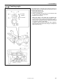
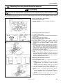
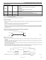
3.Warning labels
The following warning labels appear on the sewing machine.
Please follow the instructions on the labels at all times when using the machine. If the labels have been removed or are
difficult to read, please contact your nearest Brother dealer.
<T-8420A, 8720A>
1
2
Be sure to connect the ground. If the ground
connection is not secure, you run a high risk of
receiving a serious electric shock, and problems with
correct operation may also occur.
3
Direction of operation
Safety devices:
(A) Finger guard
(B) Thread take-up cover
(C) Belt cover
2955M
Oil pan
2956M
2954M
iv
T-8400A, 8700A
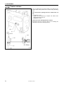
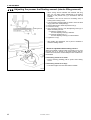
<T-8421A, 8422A, 8722A>
1
2
3
Be sure to connect the ground. If the ground connection is not
secure, you run a high risk of receiving a serious electric shock,
and problems with correct operation may also occur.
4
Direction of operation
Safety devices:
(A) Finger guard
(B) Thread take-up cover
Oil pan
2867M
Control box
2083M
2868M
T-8400A, 8700A
v
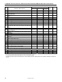
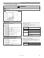
CONTENTS
1. MACHINE SPECIFICATIONS .............. 1
4-10. Unifying stitch lengths for normal feed and
2. NOTES ON HANDLING ....................... 5
reverse feed ................................................ 23
3. LUBRICATION SYSTEM ..................... 6
4-11. Rotary hook bases position......................... 24
4-12. Clearance between rotary hook and needle
3-1. Needle bar and thread take-up, needle bar
plate ............................................................ 26
rocking mechanism and presser bar bushing
(minimum lubrication type)............................ 6
4-13. Clearance between rotary hook and
opener......................................................... 27
3-2. Needle bar and thread take-up, needle bar
rocking mechanism and presser bar bushing
4-14. Presser foot height ...................................... 27
(semi dry type) .............................................. 7
4-15. Installing the feed dog ................................. 28
3-3. Feed regulator and feed rocker shaft
4-16. Feed dog position........................................ 28
bushing (both semi dry and minimum
lubrication type)............................................. 8
3-4. Rotary hook base (both semi dry and
minimum lubrication type)............................. 9
4-17. Feed dog height .......................................... 29
4-18. Feed dog angle ........................................... 30
4-19. Tension release........................................... 31
4-20. Thread trimming timing (Models with
3-5. Feed bar (both semi dry and minimum
thread trimmer: T-8422A, 8722A) ............... 32
lubrication type)............................................. 9
4. ADJUSTMENT ..................................... 10
4-21. Replacing the fixed knife and movable knife
(Models with thread trimmer:
4-1. Safety switch position (DD motor
T-8422A, 8722A)........................................... 34
specifications: T-8421A, 8422A, 8722A) ...... 10
4-22. Movable knife position (Models with thread
4-2. Thread take-up amount for thread take-up
trimmer: T-8422A, 8722A) .......................... 35
spring ............................................................ 11
4-23. Plate spring (Models with thread trimmer:
4-3. Thread take-up spring tension ...................... 12
4-4. Thread take-up amount ................................ 13
T-8422A, 8722A) ........................................ 37
4-24. Tension release wire (Models with thread
trimmer: T-8422A, 8722A) .......................... 38
4-5. Upper shaft and lower shaft timing
(Under-table motor specifications:
4-25. Thread wiper (Models with thread trimmer:
T-8420A, 8720A)........................................... 14
4-6. Upper shaft and lower shaft timing
T-8422A, 8722A) ........................................ 39
4-26. Adjusting the needle up stop position ......... 41
(DD motor specifications:
T-8421A, 8422A, 8722A) .............................. 15
4-7. Needle drop forward-back position ............... 17
4-8. Needle and rotary hook timing...................... 20
4-27. Adjusting the treadle ................................... 41
4-28. Adjusting the rotary hook lubrication
amount ........................................................ 42
4-29. Adjusting the presser foot floating amount
4-9. Quick reverse device (DD motor specifications:
T-8421A, 8422A, 8722A) .............................. 22
T-8400A, 8700A
(minute lifting amount) ................................ 43
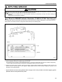
5. APPLYING GREASE ........................... 44
5-1. When the GREASE indicator illuminates
(T-8420A, 8720A: Semi dry type) ................. 44
5-2. When “GREASEUP” appears (T-8421A,
11. CONTROL BOX AND MOTOR
(T-8421A, 8422A, 8722A) .................. 76
11-1. Removing and installing the control box ..... 76
11-2. Control box and motor rating plate.............. 77
8422A, 8722A: Semi dry specifications) ....... 47
6. GREASE APPLICATION AND
LUBRICATION WHEN DISASSEMBLING
AND REPLACING PARTS....................... 50
7. SWITCHING FROM NEEDLE FEED
TO LOWER FEED................................ 53
8. REPLACING GAUGE PARTS
(CHANGING THE NEEDLE WIDTH) ... 55
9. FUNCTION SETTINGS
(T-8421A, 8422A, 8722A) .................... 57
9-1. Maximum sewing speed and start backtack
sewing speed setting methods ..................... 57
9-2. Using the LOCK key ..................................... 58
9-3. Setting the DIP switches............................... 58
9-4. Setting functions ........................................... 59
9-5. Function List.................................................. 60
9-6. Clearing saved data (Initialization)................ 74
11-3. Control circuit board .................................... 79
11-4. Checking the motor and power supply ....... 81
11-5. Checking the solenoids............................... 82
12. TREADLE UNIT ASSEMBLY
(T-8421A, 8422A, 8722A) .................. 83
12-1. Types .......................................................... 83
12-2. Standard setting values .............................. 84
12-3. Setting method for standard depression
strokes ........................................................ 85
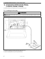
13. STANDING OPERATION PEDAL
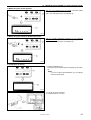
(T-8421A, 8422A, 8722A) .................. 87
13-1. Installing the foot plug ................................. 87
13-2. Connectors.................................................. 88
14. TROUBLESHOOTING ....................... 89
14-1. Sewing ........................................................ 89
14-2. Error code displays
10. CONTROL SYSTEM
(T-8421A, 8422A, 8722A) .................. 75
T-8400A, 8700A
(T-8421A, 8422A, 8722A).........................101
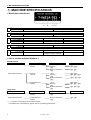
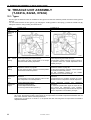
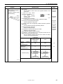
1. MACHINE SPECIFICATIONS
1. MACHINE SPECIFICATIONS
< Model plate indications >
A
A
B
C
D
B
4
Standard hook
Rotary hook
7
Large hook
0
Thread trimmer
Quick reverse
Thread wiper
Lubrication type
1
-
Use
2
○
0
-
-
4
○
○
0
Minimum lubrication
F
E
C D E
3
Semi dry
3
For light-weight and
medium- weight materials
For foundation
T
○
-
5
For heavy-weight materials
< List of models and specifications >
Standard hook
Thread trimmer
With thread trimmer
Without thread trimmer
Motor
DD motor
T-8422A
DD motor
T-8421A
Under-table motor
T-8420A
Lubrication type
(Dry)*
Semi dry
-[]3[]
Minimum lubrication
-[]0[]
Use
(-[][]3)
-[][]3, (-[][]5)
( Dry)*
Semi dry
-[]3[]
Minimum lubrication
-[]0[]
(-[][]3, -[][]F)
-[][]F, -[][]3, (-[][]5)
( Dry)*
Semi dry
-[]3[]
Minimum lubrication
-[]0[]
(-[][]3, -[][]F)
-[][]F, -[][]3, (-[][]5)
-[][]3, -[][]5
(-[][]F), -[][]3, -[][]5
-[][]F, -[][]3, -[][]5
Large hook
Thread trimmer
With thread trimmer
Motor
DD motor
T-8422A
Lubrication type
Minimum lubrication
-[]0[]
Use
-[][]3, -[][]5
Without thread trimmer
Under-table motor
T-8420A
Minimum lubrication
-[]0[]
-[][]3, -[][]5
* ( ) types are not included in the specification lineup.
It is available from local dealers by special order or by installing optional parts.
1
T-8400A, 8700A
1. MACHINE SPECIFICATIONS
< Drive motor >
Installation position
DD motor
Built into machine head
Type
Control circuit
AC servo motor (4-pole, 550W)
Microprocessor
Under-table motor
Installed under table
(obtained locally)
Clutch motor, etc.
-
< Gauge part widths (compatibility with bed and rotary hook base) >
Refer to the parts book for the availability of gauge parts for various specifications.
Model
Standard bed
Special order
T-8420A, 8421A
Max. 77 mm
T-8422A
Max. 45 mm
1.6 – 38.1 mm
T-8720A
Max. 68 mm
T-8722A
Max. 45 mm
T-8400A, 8700A
2
1. MACHINE SPECIFICATIONS
< Specifications >
T-8420A (Standard hook, Without thread trimmer, Under-table motor)
T-8421A (Standard hook, Without thread trimmer, DD motor)
-[][]F
Use
Max. sewing speed
(Dry)
Semi dry
Minimum
lubrication
and continuous
-[][]3
For light-weight and
For foundation
medium- weight
materials
3,000 rpm
3,000 rpm
3,000 rpm
1,000 rpm (T-8421A only)
4 mm
7 mm
13 mm
1 mm
Feed dog height
5 mm
56.8 mm
Thread take-up lever
No.5
51.9 mm
Thread take-up lever No.3
Needle bar stroke
Presser foot pressure
-
250 – 1,800 rpm (T-8421A only)
Lifting lever
Knee lifter
Thread take-up stroke
For heavy-weight
materials
4,000 rpm
Start backtacking
backtacking speed
End backtacking speed
Max. stitch length
Presser foot height
-[][]5
33.4 mm
7.5 – 58.5 N
Rotary hook
Needle DP x 5
(Standard/Organ)
Feed mechanism
Arm pocket width
T-8420A
T-8421A
Weight
10 – 78 N
Horizontal rotary hook (vertical axis)
Standard hook
#11
#14
#22
(#9 – #14)
(#11 – #16)
(#14 – #22)
Needle feed / Lower feed (Can be switched)
120 x 264 mm
42.5 kg
46.5 kg
T-8422A (Standard hook, With thread trimmer, DD motor)
Use
Max. sewing speed
(Dry)
Semi dry
Minimum
lubrication
and continuous
Start backtacking
backtacking speed
End backtacking speed
Max. stitch length
Presser foot height
Feed dog height
Thread take-up stroke
Needle bar stroke
Presser foot pressure
Rotary hook
Needle DP x 5
(Standard/Organ)
Feed mechanism
Arm pocket width
Weight
3
-[][]3
For light-weight and
medium- weight materials
3,000 rpm
-[][]5
For heavy-weight materials
-
3,000 rpm
4,000 rpm
3,000 rpm
250 – 1,800 rpm
1,000 rpm
4 mm
Lifting lever
Knee lifter
5 mm
7 mm
13 mm
1 mm
51.9 mm
Thread take-up lever No.3
33.4 mm
10 – 78 N
Horizontal rotary hook (vertical axis)
Standard hook
#14
#22
(#11 – #16)
(#14 – #22)
Needle feed / Lower feed (Can be switched)
120 x 264 mm
49.5 kg
T-8400A, 8700A
1. MACHINE SPECIFICATIONS
T-8720A (Large hook・Without thread trimmer, Under-table motor)
T-8722A (Large hook・With thread trimmer, DD motor)
-[][]3
For light-weight and
medium- weight materials
Use
Max.
sewing Minimum
speed
lubrication
Start backtacking and continuous
backtacking speed
End backtacking speed
Max. stitch length
Presser
foot Lifting lever
height
Knee lifter
Feed dog height
Thread take-up stroke
Needle bar stroke
Presser foot pressure
Rotary hook
Needle DP x 5
(Standard/Organ)
Feed mechanism
Arm pocket width
Weight
T-8720A
T-8722A
-[][]5
For heavy-weight materials
3,000 rpm
250 – 1,800 rpm (T-8722A only)
1,000 rpm (T-8722A only)
7 mm
7 mm
13 mm
1 mm
62.4 mm
Thread take-up lever No.6
33.4 mm
10 – 78 N
Horizontal rotary hook (vertical axis)
Large hook
#14
#22
(#11 – #16)
(#14 – #22)
Needle feed / Lower feed (Can be switched)
120 x 264 mm
42.5 kg
49.5 kg
T-8400A, 8700A
4
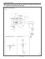
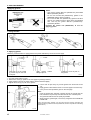
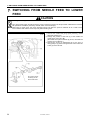
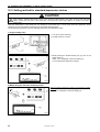
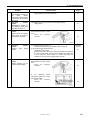
2. NOTES ON HANDLING
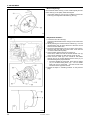
2. NOTES ON HANDLING
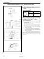
About the machine set-up location
Do not set up this sewing machine near other equipment
such as televisions, radios or cordless telephones,
otherwise such equipment may be affected by electronic
interference from the sewing machine.
The sewing machine should be plugged directly into an AC
wall outlet. Operation problems may result if extension
cords are used.
2086M
<T-8420A, 8720A>
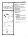
Carrying the machine
2959M
The machine should be carried by the arm by two people
as shown in the illustration.
<T-8420A, 8720A>
Make sure that the machine pulley does not turn.
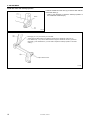
<T-8421A, 8422A, 8722A>
Hold the motor cover (A) by hand also so that the pulley
does not rotate.
<T-8421A, 8422A, 8722A >
2870M
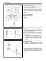
Tilting back the machine head
Hold section (B) with your foot so that the table does not
move, and then push the arm with both hands to tilt back
the machine head.
2871M
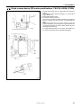
Returning the machine head to the upright position
1. Clear away any tools, etc. which may be near the table
holes.
2. While holding the face plate with your left hand, gently
return the machine head to the upright position with your
right hand.
2872M
5
T-8400A, 8700A
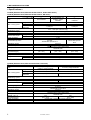
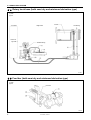
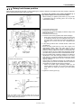
3. LUBRICATION SYSTEM
3. LUBRICATION SYSTEM
3-1. Needle bar and thread take-up, needle bar rocking mechanism and
presser bar bushing (minimum lubrication type)
Thread take-up
mechanism
Two
Oil terminal
Oil tank
3007M
[G] Lubrication points requiring grease
(1) Wick
(2) Felt
Folded over twice
Needle bearing
Presser bar bush
Two
Oil recovery
from jaw
3008M
T-8400A, 8700A
6
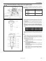
3. LUBRICATION SYSTEM
3-2. Needle bar and thread take-up, needle bar rocking mechanism and
presser bar bushing (semi dry type)
[G] Lubrication points requiring grease
(1) to (7) require grease application.
(8) Wick
[Grease applied]
Thread take-up mechanism
Presser bar bush
3009M
3010M
7
T-8400A, 8700A
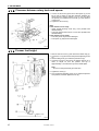
3. LUBRICATION SYSTEM
3-3. Feed regulator and feed rocker shaft bushing (both semi dry and
minimum lubrication type)
The lubricating oil inside the oil cover is used for lubricating these parts.
[G] Lubrication points requiring grease
(1) to (7) Wick
(8) Felt
A Felt
Top of bed
Feed regulator
Feed regulator
Needle
bearing
Felt A
Felt A
Oil cover
3011M
T-8400A, 8700A
8
3. LUBRICATION SYSTEM
3-4. Rotary hook base (both semi dry and minimum lubrication type)
(1) Wick
(2) Felt
<Left side>
Oil tank
<Right side>
Air bleeding
< Same as
right side >
Needle bearing
3012M
3-5. Feed bar (both semi dry and minimum lubrication type)
(1) Wick
(2) Felt
Feed bar
3098M
9
T-8400A, 8700A
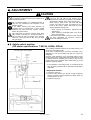
4. ADJUSTMENT
4. ADJUSTMENT
CAUTION
Disassembly, assembly, maintenance and inspection
of the sewing machine should only be carried out by
a qualified technician.
Turn off the power switch and disconnect the power
cord from the wall outlet at the following times,
otherwise the machine may operate if the treadle is
depressed by mistake, which could result in injury.
When using a clutch motor, the motor will keep
turning even after the power is switched off as a
result of the motor’s inertia. Wait until the motor
stops fully before starting work.
Ask your Brother dealer or a qualified electrician to
carry out any maintenance and inspection of the
electrical system.
If any safety devices have been removed, be
absolutely sure to re-install them to their original
positions and check that they operate correctly
before using the machine.
Use both hands to hold the machine head when
tilting it back or returning it to its original position. If
only one hand is used, the weight of the machine
head may cause your hand to slip, and your hand
may get caught.
・ When carrying out inspection, adjustment and
maintenance
・ When replacing consumable parts such as the
rotary hook and knife
If the power switch needs to be left on when carrying
out some adjustment, be extremely careful to
observe all safety precautions.
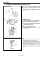
4-1. Safety switch position
(DD motor specifications: T-8421A, 8422A, 8722A)
The standard installation position for the safety switch (1) is
shown in the illustration at left.
At the time of shipment from the factory, dimension (A) is
adjusted to 3 mm, and normally this does not need to be
readjusted.
However, if the dimensions of the work table make it so that
the gap between the machine bed and the table hole is wider
or narrower than the standard gap (1.5 mm), it may have an
adverse effect on the operation of the safety switch (1). If this
happens, adjust as follows.
If the spring operating stroke is too short,
the safety switch will not operate.
Machine bed
Table
* If the operation of the safety switch (1) is affected in this
way, the sewing machine will not start when the treadle is
depressed.
< Adjustment method >
1. Loosen the screw (2).
2. Move the safety switch (1) to the left or right to adjust its
position so that the gap (B) between the safety switch (1)
and the table is 4.5 mm.
3. Tighten the screw (2).
3013M
T-8400A, 8700A
10
4. ADJUSTMENT
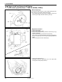
4-2. Thread take-up amount for thread take-up spring
3014M
< Measurement method >
Pass upper thread through
thread take-up
The standard thread take-up length for thread take-up
springs R (1) and L (2) is 7 mm. You can adjust the thread
take-up amounts by changing the heights of the stopper
[right] (3) and the stopper [left] (4).
* The standard heights of the stopper [right] (3) and the
stopper [left] (4) are when the are aligned with the tension
stud (5).
< Adjustment method >
The thread take-up amount for a thread take-up spring
decreases when the height of the stopper is increased.
Height of stopper [right] (3) [for right thread]
1. Loosen the screw (6), and then slide the stopper [right] (3)
to adjust the thread take-up amount.
2. Tighten the screw (6).
Height of stopper [left] (4) [for left thread]
1. Loosen the screw (7), and then slide the stopper [left] (4)
to adjust the thread take-up amount.
2. Tighten the screw (7).
3015M
Note:
If using a thread trimming sewing machine, the trailing
length for the left upper thread may become shorter after
thread trimming because of the twist in the thread.
The trailing length is normal if the upper thread length is
35 mm when the thread is pulled from the needle hole. If
the thread length is shorter than this, reduce the thread
take-up amount of the thread take-up spring.
However, if using fine threads (such as #50 polyester
thread or finer), reducing the thread take-up amount too
much may cause the right upper thread to be cut too short,
or it might result in thread trimming errors for the left upper
thread.
35mm or more
Pull
Trailing thread
3016M
11
T-8400A, 8700A
4. ADJUSTMENT
4-3. Thread take-up spring tension
< Measurement method >
Do not pass thread through
thread take-up
Upper limit position when
measuring thread take-up
amount
The standard tensions for the thread take-up spring R (1) and
thread take-up spring L (2) are as follows depending on
sewing machine specifications.
For foundation (-[][]F)
For light-weight and medium-weight materials
(-[][]3)
For heavy-weight materials (-[][]5)
0.25N
0.35N
0.70N
< Adjustment method >
Stronger
Weaker
Weaker
Stronger
Thread take-up spring R (1) [for right thread]
1. Loosen the set screw (3), and turn the adjusting thumb (4)
to adjust the tension.
2. Tighten the set screw (3).
Thread take-up spring L (2) [for left thread]
1. Loosen the tension nut (5).
2. Use a small screwdriver to turn the tension stud (6) to
adjust the tension.
3. Tighten the tension nut (5).
3017M
T-8400A, 8700A
12
4. ADJUSTMENT
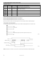
4-4. Thread take-up amount
2928M
<For non-foundation specifications>
The thread take-up amount is adjusted by how the thread is
passed through the thread amount adjuster (1).
< Using the standard thread amount adjuster (1) >
For non-foundation specifications
Do not pass the thread through the thread amount adjuster
(1). Loosen the screw (2) and slide the thread amount
adjuster (1) to the right-side position.
Do not pass the
thread through.
For foundation specifications
Pass the thread through the thread amount adjuster (1).
The standard position of the thread amount adjuster (1) is
when the screw (2) is in the center of the adjustment range.
< Adjusting the thread take-up amount >
When the thread has been passed through the thread
amount adjuster (1), the thread take-up amount becomes
less when the thread amount adjuster (1) is moved to the
right.
<For foundation specifications>
Center
It is better not to pass the thread through the thread
amount adjuster (1):
• When sewing heavy materials using a sewing machine
with foundation specifications
• When the thread take-up amount is not enough, such as
when the stitch length is increased
Pass the thread
through.
It is better to pass the thread through the thread amount
adjuster (1):
• When sewing with slippery threads such as synthetic
yarns
• When sewing light materials
• When sewing with a stitch length of 2 mm or less
• When sewing under any of the above three conditions and
you would like to prevent skipped stitches, thread
tightening problems such as looping, or thread breakages
2929M
3018M
Thread take-up
amount is too large
Thread take-up
amount is too small
Start of movement
< Guide to adjustment >
The standard thread take-up amount is when the thread
tension spring (3) starts to move when the loop is moved to
point (B) which is slightly in front of point (A) where the rotary
hook tip catches the upper thread loop and the rotary hook
thread amount is at its maximum.
• If the thread take-up amount is too large, the thread
tension spring (3) will not start to move even after point
(A) is passed.
….. This can cause skipped stitches, poor thread
tightening and thread breakages.
• If the thread take-up amount is too small, the thread
take-up spring (3) will start moving before point (B).
….. This can cause thread breakages, overtightening of
the upper thread and pulling of the seam.
The thread take-up amount required will vary depending on
the type of thread, the thickness of the material and the stitch
length, so adjust the thread take-up amount to suit the
sewing conditions.
3019M
13
T-8400A, 8700A
4. ADJUSTMENT
4-5. Upper shaft and lower shaft timing
(Under-table motor specifications: T-8420A, 8720A)
1. Remove the needle.
2. Tilt back the machine head.
3. Remove the timing belt (1).
(Gradually slide the timing belt (1) to the right while
turning the machine pulley forward.)
3020M
4. Place the timing belt (1) onto timing pulley D (2) so that
the mark (3) on timing pulley D (2)is aligned with the bed
reference line (4) when the thread take-up is at its highest
position.
(Place the timing belt (1) part of the way on and then
gradually slide the timing belt (1) to the left while turning
the machine pulley.)
3021M
< Adjustment method >
When the thread take-up is at its
highest position
When the needle bar is at its
highest position
1. Check that the mark (3) on timing pulley D (2)is aligned
with the bed reference line (4) when the thread take-up is
at its highest position.
Also at this time, check that the <A> mark on the machine
pulley is visible in about the middle of the belt cover
window.
2. Check that the <–> mark on the machine pulley is visible
in about the middle of the belt cover window when the
needle bar is at its highest position.
3. Install the needle.
3022M
T-8400A, 8700A
14
4. ADJUSTMENT
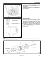
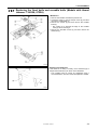
4-6. Upper shaft and lower shaft timing
(DD motor specifications: T-8421A, 8422A, 8722A)
< Before adjusting >
Check that the index mark (1) on the machine pulley and the
index mark (2) on the pulley holder are aligned.
* If the index marks (1) and (2) are not aligned, loosen the
screws (3) and align the index marks (1) and (2).
3023M
3024M
< Adjustment method >
1. Remove the needle.
2. Tilt back the machine head.
3. Remove the retaining ring (4) and then remove the pin (5)
and the washer (6).
4. Remove the screw (7), and loosen the screw (8).
(The screw (7) can be loosened by inserting a screwdriver
into the cut-away part in the oil pan (9) underneath the
table.)
5. Remove the quick reverse solenoid (10).
3025M
6. Remove the timing belt (11).
(Gradually slide the timing belt (11) to the right while
turning the machine pulley forward.)
3026M
15
T-8400A, 8700A
4. ADJUSTMENT
7. Place the timing belt (11) onto timing pulley D (12) so that
the mark (13) on timing pulley D (12) is aligned with the
bed reference line (14) when the thread take-up is at its
highest position.
(Place the timing belt (11) part of the way on and then
gradually slide the timing belt (11) to the left while turning
the machine pulley.)
3027M
< Adjustment method >
1. Check that the mark (13) on timing pulley D (12)is aligned
with the bed reference line (14) when the thread take-up is
at its highest position.
Also at this time, check that the <A> mark on the machine
pulley is visible in about the middle of the belt cover
window.
2. Check that the <−> mark on the machine pulley is visible
in about the middle of the belt cover window when the
needle bar is at its highest position.
3. Install the quick reverse solenoid (10).
4. Install the needle.
When the thread take-up is
at its highest position
When the needle bar is at
its highest position
3028M
Note:
When assembling the joint unit (15) after it has been disassembled, install so that the mark (18) on timing pulley U (17) is
aligned with the center of the screw (16) at the front.
Securely tighten
Sewing machine
operating direction
3029M
T-8400A, 8700A
16
4. ADJUSTMENT
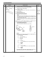
4-7. Needle drop forward-back position
< Checking method >
1. Set the stitch length dial to "0".
2. Move the needle bar (1) to its lowest position.
3. The gap between the needle bar (1) and the presser bar
(3) should be 13.3–13.7 mm at the bottom edge of the
presser bar bush (2).
If adjustment is necessary, follow the procedure below.
3030M
3031M
< Adjustment method >
1. Remove the seven screws (4) and then remove the rear
cover (5).
2. Loosen the bolt (6).
3. Move the needle bar (1) forward or back so that the gap
between the needle bar (1) and the presser bar (3) is
13.3–13.7 mm as described in <Checking method>
above.
4. Tighten the bolt (6).
5. Check once more that the gap is 13.3–13.7 mm.
(This is because the needle bar (1) may move when the
bolt (6) is tightened.)
6. Install the rear cover (5).
7. Check that the needle goes into the middle of the needle
hole in the feed dog (7).
(The needle will actually be slightly to the front when it
goes into the feed dog (7), and will be slightly to the back
when it comes out.)
The needle should not be touching the feed dog (7).
* If the needle touches the feed dog, check the steps in
"4-16. Feed dog position").
3032M
< Reference >
If distance (A) is too large
• The feed dog (7) will touch the needle when the stitch
length dial is at the maximum setting
• Skipped stitches and needle breakages may occur.
• Lower thread trimming errors at the right side and upper
thread trimming errors at the left side may occur.
If distance (A) is too small
• The feed dog (7) will touch the needle when the stitch
length dial is at the maximum setting.
• Skipped stitches and needle breakages may occur.
• Lower thread trimming errors at the left side and upper
thread trimming errors at the right side may occur.
Touches if too small
Touches if too large
3033M
17
T-8400A, 8700A
4. ADJUSTMENT
3034M
3035M
Note:
When adjusting the needle drop forward-back position, do
not move the feed rocker arm (2) and the needle bar rock
arm (3) with respect to the feed rocker shaft (1).
If they are moved, they may cause interference between the
various mechanisms, and the needle drop position may shift
when changing to lower feed.
Realignment if these parts are accidentally moved
1. Set the stitch length dial to "0".
2. Tighten the screw (4) to secure the feed rocker arm (2) to
the feed rocker shaft (1).
3. Move bolt (5) from (B) to (C).
(Be careful not to pull bolt (5) out too far, otherwise the
washer (6) may fall down.)
4. Check that the gap (A) between the needle bar (7) and
the presser bar (8) is 13.3–13.7 mm.
(If gap (A) is incorrect, adjust while referring to "Needle
drop forward-back position" on the previous page.)
5. Move bolt (5) from (C) back to (B).
(Be careful not to pull bolt (5) out too far, otherwise the
washer (6) may fall down.)
6. Check once more that the gap (A) between the needle bar
(7) and the presser bar (8) is 13.3–13.7 mm.
If gap (A) is incorrect:
1) Loosen the screw (9).
2) Turn the needle bar rock arm (3) to adjust the gap
(A) between the needle bar (7) and the presser bar
(8) to 13.3–13.7 mm.
3) Tighten the screw (9).
(Be careful not to move the needle bar rock arm (3)
sideways at this time. If it is moved sideways, the
needle bar rocker link (10) may move out of
alignment. Refer to "Needle bar rocker link
sideways position" on the following page for details.)
4) Check once more that the gap (A) between the
needle bar (7) and the presser bar (8) is 13.3–13.7
mm.
7. Check that the needle goes into the middle of the needle
hole in the feed dog (11).
If the needle touches the feed dog (11), adjust the position
of the feed dog (11) to match the needle position. (Refer
to "4-16. Feed dog position".)
Do not fully remove the
bolt (5) so this does not
fall down.
3036M
T-8400A, 8700A
18
4. ADJUSTMENT
Needle bar rocker link sideways position
Install the needle bar rocker arm (3) so that it is flush with the
feed rocker shaft (1).
* Refer to the following to check the sideways position of
the needle bar rocker link (10).
Flush
3037M
A small gap (0–1 mm) is necessary on both sides.
* These gaps are determined by the sideways position of the needle bar rocker arm (3).
* If no clearance (0–1 mm) can be obtained even though the needle bar rock arm (3) and the
feed shaft (1) are installed flush, you will need to adjust the sideways position of the feed
shaft (1).
Gap is almost 0 mm.
3038M
19
T-8400A, 8700A
4. ADJUSTMENT
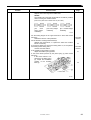
4-8. Needle and rotary hook timing
1. Set the stitch length dial to the actual length of the stitches
to be sewn.
Standard stitch length
Specifications
-[][]F
-[][]3
-[][]5
Stitch length dial
2
2
3
2. Remove the rubber cap (1).
3. Loosen the screw (5) and move the needle bar (2) up or
down to adjust so that the top reference line (3) on the
needle bar (2) is aligned with the bottom edge of the
needle bar bracket (4) when the needle bar (2) is at its
lowest position.
(Be careful not to turn the needle bar (2) at this time.)
4. Securely tighten the screw (5).
5. At this time, the gaps (A) and (B) between the needle (6)
and the front of the feed dog (7) should be about the
same as each other.
Needle bar lowest position
3039M
6. Turn the machine pulley forward to raise the needle bar
(2) until the reference line ((8) or (9), depending on the
feed condition) on the needle bar (2) is aligned with the
bottom edge of the needle bar base (4).
7. In this condition, secure the machine pulley with tape or
similar, so that the needle bar (2) will not move.
The procedure up to this point determines the needle bar lift
amount.
Note:
If the needle bar lift amount is too large
• It will cause poor tightening in the right thread.
• Both the left and right seams will become uneven, and
skipped stitches or thread breakages will occur.
• Upper thread trimming errors may occur, or the upper
thread may be cut too short (models with thread trimmer).
• The upper thread trailing length will be too long (models
with thread trimmer).
Lower feed
Needle feed
3040M
If the needle bar lift amount is too small
• Skipped stitches and thread breakages will occur.
• The upper thread trailing length will be too short (models
with thread trimmer).
T-8400A, 8700A
20
4. ADJUSTMENT
3041M
8. Loosen the screws (10), and then remove rotary hook
base cover FL (11) and FR (12).
(The screws (10) is designed so that they cannot be
removed from the rotary hook base cover FL (11) and FR
(12) to prevent them from being lost.)
9. Loosen the set screws (13) (three each at left and right).
(However, be careful not to loosen them too much,
otherwise the set screws (13) will touch the inside surface
of the rotary hook base and the pinion gear (14) will not be
able to turn. Loosen the set screws by the minimum
amount which will still allow the rotary hook to move
freely.)
10. Turn the rotary hook by hand to align the rotary hook tip
(15) with the middle of the needle. (Do not turn the
machine pulley at this time.)
11. Tighten the set screws (13).
(Tighten the three set screws (13) a little bit at a time in
order so that the pinion gear (14) does not become
tilted.)
12. Remove the tape that is securing the machine pulley.
3042M
Color in
Mark
3043M
13. Use an oil-based marker pen to color in the hollow of the
needle.
14. With the needle raised, turn the machine pulley forward
while pushing the needle against the rotary hook tip (15)
with your finger to make a mark from the rotary hook tip
(15) in the hollow of the needle.
15. Check that the distance (C) from the intersection
between the mark from the rotary hook tip (15) and the
center line of the needle to the top edge of the needle
hole is 1–1.5 mm.
* If the distance is not 1–1.5 mm, loosen the screw (15)
again and adjust the height of the needle bar.
* If dimension (C) has been adjusted, the highest
reference line (3) on the needle bar (2) may be hidden
by the bottom edge of the needle bar base (4) when
the needle bar is at its lowest position, but this is not a
problem.
If using a thread such as polyester thread which does
not easily form stable loops
* If problems such as skipped stitches or upper thread
breakages occur, set the above distance (C) to 0.7–0.8
mm to make it easier for the rotary hook tip (15) to catch
the upper thread loop.
Note:
• When the stitch length is changed, distance (C) will also
change, so re-check distance (C) at such times.
• During quick reverse operation, distance (C) for the left
needle will become shorter, so do not set it to less than
0.7 mm, otherwise the rotary hook tip (15) may touch the
projection (D) and this could damage the rotary hook tip
(15).
Needle bar
lowest position
Mark
3044M
21
T-8400A, 8700A
4. ADJUSTMENT
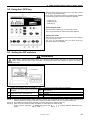
4-9. Quick reverse device (DD motor specifications: T-8421A, 8422A, 8722A)
3045M
1. Set the stitch length dial 1/2 a step below the maximum
setting.
(For example, if the maximum setting is 4, set the stitch
length dial to 3.5.)
2. Tilt back the machine head.
3. Loosen the screws (1) and (2).
(The screw (2) can be loosened by inserting a screwdriver
into the cut-away part in the oil pan (3) underneath the
table.)
4. When the reverse lever (4) is fully lowered, move the
solenoid bracket (7) so that there is no gap between the
quick reverse solenoid (5) and the rubber stopper (6), and
then tighten the screw (1).
* If the gap mentioned above is too large, the operation of
the quick reverse solenoid (5) will become sluggish.)
3046M
3047M
T-8400A, 8700A
22
4. ADJUSTMENT
4-10. Unifying stitch lengths for normal feed and reverse feed
1822M
Normal feed
The following explains how to make the stitch lengths the
same for normal feed and reverse feed.
1. Set the stitch length dial to the actual stitch length that is
to be sewn.
Standard stitch lengths
Model
Specifications
Reverse feed
T-8420A
T-8421A
T-8422A
11 stitches
T-8720A
T-8722A
3048M
Stitch length dial
-[][]F
2
-[][]3, -[][]5
3
-[][]3, -[][]5
4
2. Turn the machine pulley by hand or run the sewing
machine at low speed (220 rpm) and sew using normal
feed and reverse feed (11 stitches each way).
3. If adjustment is necessary, carry out the following.
1) Remove the rear cover.
2) Loosen the set screw (1).
3) Turn the eccentric shaft (2) within a range of 90
degrees to adjust.
(If you turn the eccentric shaft more than 90 degrees,
the adjustment will be reversed.)
The standard position is when the index mark (3) on
the eccentric shaft (2) is aligned with the set screw (1).
• If the stitch length is longer for normal feed
than for reverse feed
Turn the eccentric shaft (2) in the direction of A.
• If the stitch length is shorter for normal feed
than for reverse feed
Turn the eccentric shaft (2) in the direction of B.
4. After adjusting, securely tighten the set screw (1) while
gently pushing the eccentric shaft (2) toward the feed
regulator (4).
3049M
23
T-8400A, 8700A
4. ADJUSTMENT
4-11. Rotary hook bases position
When changing the gauge part width, or when adjusting the clearance between the needle and the rotary hook tip, adjust the
left and right movement of the rotary hook bases.
< If moving the position of the rotary hook bases by a
3050M
large amount (about 1 mm or more at one side) >
* When loosening or tightening the screws (1) to (5), insert
a screwdriver into the cut-away part in the oil pan (6)
underneath the table.)
3051M
Eccentric side
faces upward
Models with thread trimmer
1. Tilt back the machine head.
2. Loosen the four screws (1).
3. Loosen the two screws (2) slightly so that the rotary hook
base (7) can move.
4. Loosen the two screws (3).
5. Loosen the set screws (4) (three each at left and right).
* Each group of three set screws (4) has one screw with
a rounded tip that fits into the V-shaped screw stop in
the lower shaft. Loosen the set screws only slightly so
that they do not come out from the V-shaped screw
stop.
6. If the sewing machine has a thread trimmer, loosen the
two bolts (8).
7. Move the rotary hook base (7) to the left or right to its
approximate position (when the rotary hook tip (9) is
approximately 0.2 mm away from the needle in its final
position), and then tighten the screws (1). At this time, the
eccentric sides of the two needle upper positioning shafts
(5) will be facing upward as shown in the illustration at left.
8. Turn the needle upper positioning shafts (5) to make fine
adjustments to the left and right positions of the rotary
hook bases (7) so that the clearance between the needle
and the rotary hook tip (9) is 0.05 mm or less but so that
they do not touch.
At this time, the clearance between the needle and the
needle guard (10) should be smaller than the clearance
(A) between the needle and the rotary hook tip (9).
* When the needle upper positioning shafts (5) are
turned until they feel stiff, you can then move the rotary
hook bases (7) easily by running your hand along
them.
9. Tighten the screws (2) and (3).
3052M
0.05 mm or less
Distance (A) or less
When the needle is bent toward the rotary hook tip (9), the
needle and rotary hook tip (9) should not touch even if the needle
and the needle guard (10) do touch.
T-8400A, 8700A
24
4. ADJUSTMENT
Touching
gently
Touching
gently
10. Lastly, tighten the set screws (4) (three each at left and
right).
At this time, push the right spiral gear (11) gently to the
right (so that it gently touches the thrust washer (12)
inside the rotary hook base (7)). Also push the left spiral
gear (13) gently to the right (so that it gently touches the
thrust washer (15) in between the spiral gear (13) and
the cover (14)) when tightening the set screws.
Note:
After tightening the spiral gears (11) and (13), do not try
and force the needle upper positioning shafts (5) to turn in
order to make fine adjustments to the sideways positions
of the rotary hook bases (7), otherwise damage may
result.
3053M
3100M
11. For thread trimming sewing machines
1) Tighten the bolts (8).
2) Lower the needle bar to its lowest position.
3) Loosen the nut (16).
4) Turn the adjusting connecting rod (21) to adjust so
that the roller (19) of the main lever (18) goes into
the groove in the thread trimmer cam (20) when the
thread trimmer solenoid (17) is pressed.
5) Tighten the nut (16).
3101M
< If moving the position of the rotary hook bases by a small amount (about 1 mm at one side) >
For example:
• When readjusting the clearance between the needle and the rotary hook tip
• When changing small-width gauge parts (such as 6.4 mm ← → 4.8 mm or 4.8 mm ← → 3.2 mm)
The amount of eccentricity in the needle upper positioning shafts (5) (refer to the illustration on the previous page) is 1.7 mm.
Therefore, when adjusting the sideways movement of the rotary hook bases (7) to about 1 mm to one side, you do not need
to loosen the screws (1). Carry out steps 1., 3., 4., 5., 6., 8., 9., 10. and 11. in "If moving the position of the rotary hook bases
by a large amount" on the previous page.
(Steps 2. and 7. are not required.)
25
T-8400A, 8700A
4. ADJUSTMENT
4-12. Clearance between rotary hook and needle plate
The clearance (A) between the rotary hook (1) and the
needle plate (2) is adjusted as follows at the time of shipment
from the factory.
Model
Without thread trimming
T-8420A
T-8421A
T-8720A
With thread trimming
T-8422A
T-8722A
Distance (A)
0.9 – 1.2 mm
1.4 – 1.7 mm
3054M
3055M
• Check clearance (A) each time parts such as the rotary
hook (1) and the needle plate (2) that affect clearance (A)
are replaced.
• To adjust clearance (A), replace the thrust ring (4) that is
in between the rotary hook (1) and the rotary hook base
(3).
• Three types of thrust ring (4) are available. Measure the
thickness of the thrust ring (4) that is currently being used,
and replace it with a thrust ring (4) of the appropriate
width.
Part code
SA4444-001
SA4038-001
S09260-001
Thickness
0.8 mm
1.0 mm
1.2 mm
• When replacing the rotary hook (1), loosen the three set
screws (5). Be careful not to lose the thrust ring (4) at this
time.
Touching gently
Note:
There is a piece of felt (7) for lubrication at the base of the
rotary hook shaft (6). Gently press down on the rotary
hook (1) when tightening the set screws (5) so that the
rotary hook (1) does not lift up.
If the clearance is too large
• The inner rotary hook may come out from the needle
plate (2).
If the clearance is too small
• Poor thread tightening may occur.
• Lower thread trimming errors may occur (models with
thread trimmer).
• The right upper thread may be cut too short (models
with thread trimmer).
* These problems may occur particularly if the stitch
length is large or when carrying out thread trimming
during chaining-off.
3056M
T-8400A, 8700A
26
4. ADJUSTMENT
4-13. Clearance between rotary hook and opener
1. Loosen the set screw (3) and move the opener (1) to the
left or right to adjust so that the clearance between the
rotary hook (2) and the opener (1) is 0.1–0.3 mm when
the opener (1) is pulled as far as it will go in the direction
of the arrow.
2. Tighten the set screw (3).
Note:
If the clearance is too large
• Upper thread trimming errors may occur (models with
thread trimmer).
• The right upper thread may be cut too short (models with
thread trimmer).
If the clearance is too small
• The rotary hook may become damaged.
• The opener (1) may become damaged.
3057M
4-14. Presser foot height
3058M
1. Remove the rear cover (1) and remove the rubber cap (2).
2. Loosen the nut (3) and loosen the presser adjusting screw
(4).
3. Use the lifting lever (5) to raise the presser foot (6).
4. Loosen the screw (7) and move the presser bar (8) up or
down to adjust so that the presser foot (6) is
approximately 7 mm above the top of the needle plate.
Note:
Do not turn the presser bar (8) at this time.
5. Tighten the screw (7).
6. Turn the presser adjusting screw (4) to adjust the presser
foot pressure, and then tighten the nut (3).
Approx. 7mm
3059M
27
T-8400A, 8700A
4. ADJUSTMENT
4-15. Installing the feed dog
1. Install the feed dog (1) to the feed bar (2) with the two
screws (3).
2. Tighten the feed dog support set screw (4) so that the tip
of the set screw (4) touches the bottom of the feed dog
(1).
3. Tighten the nut (5) to secure the set screw (4).
Touch
* The set screw (4) is not used for installing the feed dog at
an angle.
3060M
4-16. Feed dog position
3061M
< Forward-back position adjustment >
Carry out this adjustment if the needle and the needle hole in
the feed dog are not positioned correctly even though the
clearance between the needle bar and the presser bar
(13.3–13.7 mm) is correct.
1. Loosen the two screws (1).
2. Turn the feed rocker base arm (3) to adjust so that the
needle drops into the middle of the needle hole in the feed
dog (2).
(The needle will actually be slightly to the front when it
goes into the feed dog (2), and will be slightly to the back
when it comes out.)
3. Tighten the screw (1).
Note:
Do not overtighten the screw (1), otherwise it will
damage the feed rocker base arm (3).
Needle
3062M
< Left-right position adjustment >
Should not be
touching at
any points
Adjust so that neither side of the feed dog touches the
needle plate (4) when the needle plate (4) is secured to the
bed with the screws (5) and (6).
If the needle plate and the feed dog are touching, loosen the
screw (1) and move the feed rocker base arm (3) sideways
to adjust.
3063M
T-8400A, 8700A
28
4. ADJUSTMENT
4-17. Feed dog height
Turn the machine pulley forward until the feed dog (1) is at its
highest position, and then adjust so that the feed dog
(1)protrudes 0.9–1.1 mm from the top of the needle plate (2).
3064M
3065M
1. Tilt back the machine head.
2. Loosen the screw (3) just enough so that the feed bar (4)
can slide.
3. Turn the height adjustment screw (5) as shown in the
illustration to adjust the height of the feed dog (1).
4. Securely tighten the screw (3).
5. Recheck the height of the feed dog (1).
Note:
If the feed dog is too high
• The feed dog may touch the needle plate.
• The stitch length may become longer than the stitch
length dial setting.
• Thread tightening may be poor when using thick threads.
• It may be difficult to obtain uniform stitch lengths for
normal feed and reverse feed.
• Lower thread trimming errors may occur (models with
thread trimmer).
If the feed dog is too low
• The stitch length may become shorter than the stitch
length dial setting.
• It may be difficult to obtain uniform stitch lengths for
normal feed and reverse feed.
• The feed dog may touch the movable knife (models with
thread trimmer).
• Large variations in stitch length may occur at slow and
fast sewing speeds.
Lower
Higher
3066M
29
T-8400A, 8700A
4. ADJUSTMENT
4-18. Feed dog angle
The standard angle for the feed dog is when the mark (2) on
the feed bar shaft (1) is aligned with the reference line (4) on
the feed rocker base arm (3).
1. Tilt back the machine head.
2. Loosen the set screw (5).
3. Insert a screwdriver into the slit (6) in the feed bar shaft
(1), and turn it to make the adjustment.
4. Tighten the set screw (5).
Front raised
Standard
* When the angle of the feed dog is adjusted, the
forward-back position of the feed dog will change. Loosen
the two screws (7) and adjust the forward-back position of
the feed dog in accordance with the needle (for lower feed,
in accordance with the needle plate).
* In addition, when the angle of the feed dog is adjusted,
the height of the feed dog will also change, so readjust the
height of the feed dog.
Front lowered
3067M
T-8400A, 8700A
30
4. ADJUSTMENT
4-19. Tension release
3005M
Carry out adjustments as follows based on the status of the
tension discs when presser foot is raised using the lifting
lever.
If the tension disc opening amount is smaller than 0.8
mm
1. Loosen the nut (1).
2. Tighten the set screw (2) to adjust the tension disc
opening amount to 0.8 mm.
3. Tighten the nut (1).
If the tension disc opening amount is normal
Check that the tip of the set screw (2) is touching the
underside of the tension release plate (4).
Rear of
sewing machine
3006M
31
T-8400A, 8700A
4. ADJUSTMENT
4-20. Thread trimming timing (Models with thread trimmer: T-8422A, 8722A)
3068M
< Checking method >
1. Remove the needles.
2. Tilt back the machine head.
3. While pressing the thread trimmer solenoid (1), turn the
machine pulley forward until the machine pulley becomes
stiff to turn (the point where the movable knife starts
moving).
4. The "T" mark on the machine pulley must be aligned with
the mark (2) on the motor cover.
At this time, the allowable range for the "T" mark is within
2 mm from the center of the mark (2).
* Check the thread trimmer timing according to the position
of the "T" mark when the movable knife makes its first
slight movement.
3069M
3070M
If the thread trimming timing is too early
• If it is extremely early (4 mm or more), thread trimming
errors will occur.
• The right upper thread may be cut extremely short.
• The upper thread trailing length will be too long after
thread trimming.
If the upper thread trailing length is too long, it will not be
picked up by the pre-tension and the lower thread holding
performance will become poorer.
(The correct upper thread trailing length after thread
trimming is 33–45 mm.)
Early
3071M
Late
Note:
If the thread trimming timing is too late
• If it is extremely late (4 mm or more), thread trimming
errors will occur.
• The upper thread trailing length will be too short after
thread trimming (about 30 mm).
[Checking method]
1. Open the slide plate.
2. Under actual sewing conditions, turn the machine
pulley to cut the threads.
3. If thread trimming is normal, the thread will be trimmed
when the upper thread is held by the loop spreader (3)
of the rotary hook as shown in the illustration.
If the thread trimming timing is late, the thread will
come out of the loop spreader (3) when the thread is
cut and the upper thread will be too short.
Upper thread
T-8400A, 8700A
32
4. ADJUSTMENT
< Before adjusting >
Check that the index mark (1) on the machine pulley and the
index mark (2) on the pulley holder are aligned.
* If the index marks (1) and (2) are not aligned, loosen the
screws (3) and align the index marks (1) and (2).
3023M
3072M
< Adjustment method >
1. Loosen the four set screws (4).
(Check that the thread trimmer cam (5) is free of the lower
shaft (6).)
2. While pressing the thread trimmer solenoid (7), turn the
thread trimmer cam (5) in the direction of the arrow until it
starts to become stiff to turn.
3. Secure the thread trimmer cam (5) so that it cannot move,
and then align the mark (8) on the motor cover with the
"T" mark on the machine pulley.
4. At this position, tighten the four set screws (4).
At this time, make sure that the thread trimmer cam (5)
cannot move sideways (so that there is no gap at (A)).
5. Check that the mark (9) in the middle of the thread
trimmer cam (5) is roughly aligned with the mark (11) on
the ball bearing bush (10) at this time.
* The same applies for lower feed. There are two marks
(11) on the ball bearing bush (10) -- one for needle
feed and one for lower feed -- and the second mark
should be almost opposite the first.
6. Repeat the steps in "Checking method" on the previous
page.
3073M
33
T-8400A, 8700A
4. ADJUSTMENT
4-21. Replacing the fixed knife and movable knife (Models with thread
trimmer: T-8422A, 8722A)
3074M
< Removal >
1. Remove the needles and raise the presser foot.
2. Loosen the screw (1), remove the pan screw (2), and then
remove the needle plate (3).
3. Remove the screws (4) and then remove the movable
knife (5).
* Be careful not to damage the edge of the movable
knife (5) when removing it.
4. Remove the shoulder screws (6) and then remove the
fixed knife (7).
3075M
Sharpening the fixed knife
If the thread is not being cut easily, use a whetstone (8) to
sharpen the fixed knife (7) as shown in the illustration.
* The movable knife (5) cannot be sharpened using a
normal whetstone, and so it should be replaced if needed.
3076M
T-8400A, 8700A
34
4. ADJUSTMENT
3077M
< Installation >
1. Turn the machine pulley by hand until the opener (1) is
being pulled as far as possible in the direction of the arrow,
and then secure the machine pulley so it will not turn.
2. Provisionally install the movable knife (2) with the screws
(3).
* Install the movable knife (2) above the plate spring (4).
3. While pressing the top of the movable knife (2) with your
finger, slide the movable knife (2) until the gap between
the tip of the movable knife (2) and the stopper (5) is
0.05–0.2 mm, and then securely tighten the screws (3).
* If the movable knife (2) and the stopper (5) are touching
or if the gap is too large, thread trimming errors will
result.
4. Install the fixed knife (6) to the needle plate (7) with the
shoulder screws (8).
5. Install the needle plate (7) with the screw (9) and the pan
screw (10).
6. Install the needles to the needle clamps and lower the
presser foot.
3078M
4-22. Movable knife position (Models with thread trimmer: T-8422A, 8722A)
< Vertical position adjustment >
Should be no
gaps
1. Remove the needle plate.
2. Loosen the set screw (2) of the set collar (1) and the
screw (4) of the thread trimmer lever (3).
3. Move the movable knife lever (7) up or down to adjust so
that the movable knife (5) gently touches the movable
knife bracket (6).
4. Adjust the set collar (1) and the thread trimmer lever (3)
so that there are no gaps between them and the rotary
hook bases, and then tighten the set screw (2) and the
screw (4).
Note:
If the movable knife is below the movable knife bracket
• The operation of the thread trimming mechanism will
become stiff and the sewing machine may stop.
• The threads will not be cut cleanly.
If the movable knife is above the movable knife bracket
• Thread trimming errors will occur.
• The movable knife will touch the sewing machine bed and
the sewing machine will stop.
• Lower thread holding will become poor.
3079M
35
T-8400A, 8700A
4. ADJUSTMENT
3080M
< Forward-back position adjustment >
The standard installation distances for the movable knife (5)
are shown in the illustration.
If adjustment is necessary, loosen the screws (8) and (9) of
the thread trimmer lever and move the movable knife (5)
back and forth.
3081M
Note:
When adjusting the position of the movable knife, the installation distances shown in the illustration above should be within ±
0.5–1 mm.
If the movable knife is to the front (if the distances are smaller than the standard distances)
• If the movable knife is a long way to the front, upper thread trimming errors will occur.
• Lower thread holding will be poorer after thread trimming.
Skipped stitches or thread pulling out will occur at the sewing start. (Take particular care of this on sewing machines with
large-capacity rotary hooks.)
• The upper thread trailing length will be too short after thread trimming.
At the right side in particular, the cut end of the upper thread will remain near the movable knife and it will cause the upper
thread to be cut extremely short.
If the movable knife is to the back (if the distances are larger than the standard distances)
• Upper thread trimming errors will occur. In addition, if the movable knife is a long way to the back, lower thread trimming
errors will occur.
• Lower thread holding will be poorer after thread trimming.
Skipped stitches or thread pulling out will occur at the sewing start. (Take particular care of this on sewing machines with
large-capacity rotary hooks.)
• The upper thread trailing length will be too long after thread trimming.
If the upper thread trailing length is too long, it will not be picked up by the pre-tension and the lower thread holding
performance will become poorer.
(The correct upper thread trailing length after thread trimming is 33–45 mm.)
• When the article being sewn is removed after thread trimming, the end of the upper thread will be pressed by the plate
spring because the upper thread trailing length is too long, and this will cause resistance.
T-8400A, 8700A
36
4. ADJUSTMENT
4-23. Plate spring (Models with thread trimmer: T-8422A, 8722A)
With twin needle sewing machines, the next article cannot be sewn unless the lower threads are held after thread trimming,
so the plate spring adjustment must be carried out correctly.
When the movable knife is not installed, the correct height for
the plate spring (1) is 7 mm.
3082M
The installation position for the plate spring (1) is shown in
the illustration at left. Loosen the screw (2) and adjust the
gap between the movable knife bracket (3) and the plate
spring (1) to 0.5–2.0 mm.
3083M
3084M
When the movable knife is installed ...
• The end of the plate spring (1) touches flush against the
underside of the movable knife (4). If it only touches at an
angle, skipped stitches or thread pulling-out problems
may occur.
In particular, these problems may occur if the upper
threads are finer than the lower threads.
• The standard positions of the movable knife (4) and the
plate spring (1) are the positions where the hook tip of the
movable knife (4) is roughly aligned with the rounded part
of the plate spring (1).
(Refer to "Forward-back position adjustment" for the
movable knife on the previous page.)
Aligned
3085M
Note:
If the lower thread holding is too strong
• Skipped stitches or thread pulling-out problems will occur at the sewing start.
If the lower thread holding is too weak, or if it is uneven at both sides
• Skipped stitches will occur at the sewing start.
37
T-8400A, 8700A
4. ADJUSTMENT
4-24. Tension release wire (Models with thread trimmer: T-8422A, 8722A)
3086M
If the upper thread trailing length is too short after thread
trimming, or if the tension discs stay open, carry out the
following adjustments.
* Lower the presser foot before making the adjustments.
If the upper thread trailing length is too short
(the tension release wire does not operate sufficiently
during thread trimming)
1. While pressing the thread trimmer solenoid (1), turn the
machine pulley forward.
2. The tension discs (4) open by approximately 0.8 mm
when the roller of the tension release lever (2) reaches
the top of the projection on the thread trimmer cam (3).
3. If the tension discs (4) do not open by approximately 0.8
mm, turn the nut (5) to adjust.
* If there is a difference between the opening amounts of
the left and right tension discs (4), you can adjust using
the set screw (6). After adjusting, secure the set screw
(6) with adhesive.
4. Check that the tension discs (4) open when the roller of
the tension release lever (2) reaches the top of the
projection on the thread trimmer cam (3), and that they
close when the roller is level.
Approx. 0.8mm
If the tension discs remain open
1. Check that the tension release lever (2) is in its original
position.
2. Check that the tension release lever spring (7) is not
removed.
3. After carrying out the above checks, adjust using the nut
(5).
* If adjustment is not possible, replace the tension release
wire (8).
Roller
Projection
3087M
Note:
If the tension disc opening is too small
• The running of the thread will be sluggish when the thread
is passing through the tension discs.
• The upper thread will pull out of the needle or the upper
thread trailing length from the needle may be too short.
If the tension disc opening is too large
• Thread tightening problems will occur.
• Damage to parts will result.
Underside of tension
3088M
T-8400A, 8700A
38
4. ADJUSTMENT
4-25. Thread wiper
(Models with thread trimmer:T-8422A, 8722A)
3089M
1. Stop the sewing machine in the needle up stop position.
2. Turn off the power switch.
3. Set the stitch length dial to "2".
< Forward-back position adjustment >
4. Remove the solenoid cover (1).
5. Loosen the screws (4) and move the solenoid (5) up or
down to adjust so that the tip of the thread wiper (3) is
0.3–0.5 mm in front of the tip of the needle when the
solenoid link (2) is pushed by hand as shown in the
illustration.
6. Securely tighten the screws (4).
7. Install the solenoid cover (1).
Note:
If the distance is too large
• The thread wiper (3) may touch the presser foot.
If the distance is too small
• Thread wiping errors will occur.
3090M
< Left-right position adjustment >
8. Pass the thread through the needle.
9. Loosen the screws (6) and move the thread wiper to the
left or right to adjust so that the hooked parts of the thread
wiper (3) securely hold the threads.
10. Securely tighten the screws (6).
Approx. 0.3mm
3091M
39
T-8400A, 8700A
4. ADJUSTMENT
3092M
Approx. 3mm
< Return position forward-back adjustment >
11. Loosen the screws (8) and move the stopper (9) up or
down to adjust so that the distance between the tip of the
thread wiper (3) and the presser bar (7) is approximately
3 mm when the thread wiper (3) has returned.
12. Securely tighten the screws (8).
* The tip of the thread wiper (3) may not hold some types
of thread, so bring the thread wiper (3) close to the
needle so that the thread can still be pulled out from the
material cleanly. In addition, check that the needle set
screw does not touch the needle wiper (3).
Note:
If the distance is too large
• The thread wiper (3) may touch the needle clamp (10).
If the distance is too small
• The thread wiper (3) may touch the presser bar (7).
3093M
3094M
< Vertical position adjustment >
13. The path for the tip of the thread wiper(3) is shown in the
illustration.
14. Loosen the screw (11) and turn the thread wiper guard
(12) to adjust so that the gap between the tip of the
needle and the thread wiper (3) is 0.5–1 mm when the
solenoid link (2) is pushed by hand as shown in the
illustration.
15. Securely tighten the screw (11).
Note:
The stopping position for the tip of the needle will vary
slightly after thread trimming.
Carry out thread trimming several times, and adjust so
that the clearance is 0.5–1 mm at the lowest position that
occurs at these times.
If the distance is too large
• Thread wiping errors will occur.
If the distance is too small
• The thread wiper (3) will touch the needle.
3095M
*
After adjusting, carry out a test sewing and check that
thread wiping is carried out correctly.
T-8400A, 8700A
40
4. ADJUSTMENT
4-26. Adjusting the needle up stop position
2210M
(-10–20)
Becomes higher
The needle up stop position will vary slightly depending on
the size of the sewing load. Adjust if the difference is too
great.
1. While pressing the needle up/down key (1), turn on the
power switch.
2. “n.0 xx” will appear in the main display (2).
(“xx” is the setting value for the needle up stop position,
and “0” is the default setting.)
or
key (3) to change the
3. Press the rightmost
setting value for the needle up stop position.
key, the setting value will increase
• If you press the
up to 20 and the needle up stop position will become
lower.
• If you press the
key, the setting value will decrease
down to -10 and the needle up stop position will
become higher.
4. Press the ENTER key (4) for two seconds or more.
A long buzzer will sound and the main display (2) will
change to stitch number display mode. (This completes
the needle up stop position setting.)
* A setting value of “10” corresponds to an angle of rotation
of approximately 10° for the upper shaft.
Becomes lower
2138M
2139M
2913M
4-27. Adjusting the treadle
2301M
< Forward depression sensitivity adjustment >
If the machine starts running at low speed when your foot is
simply resting on the treadle, or if the treadle pressure is felt
to be too weak, adjust the position (a to c) at which the
treadle spring (1) is hooked onto the treadle lever (2).
* a is the heaviest, and the setting becomes progressively
lighter at b and c.
< Backward depression sensitivity adjustment >
1. Loosen the nut (3) and turn the bolt (4).
* When the bolt (4) is tightened, the treadle operation
becomes heavier, and when it is loosened, the
operation becomes lighter.
2. Tighten the nut (3).
< Adjusting the treadle stroke >
Remove the nut (5), and then move the connecting rod joint
(6) from the position in figure A to the position in figure B.
The treadle stroke will then be increased by approximately
27%.
At this time, the treadle forward and backward depression
sensitivity will change, so readjust if necessary.
2302M
41
T-8400A, 8700A
4. ADJUSTMENT
4-28. Adjusting the rotary hook lubrication amount
CAUTION
Be careful not to touch your fingers or the lubrication amount check sheet against moving parts such as the rotary
hook or the feed mechanism when checking the amount of oil supplied to the rotary hook, otherwise injury may
result.
Use the following procedure to check the amount of oil being supplied to the rotary hook when replacing the rotary hook or
when changing the sewing speed.
< Guide to lubrication adjustment >
2998M
1. Tilt back the machine head.
2. Turn the oil adjusting screw (1) to adjust the height to
within 9–14 mm.
< Checking the lubrication amount >
More oil
Less oil
2942M
Spattered oil
1. Turn off the power switch.
2. Remove the thread from all points from the thread take-up
to the needle.
3. Remove the needle and the bobbin.
4. Use the lifting lever to lift the presser foot.
5. Turn on the power switch.
6. Run the machine at the normal sewing speed for
approximately 1 minute without sewing any material
(following the same start/stop pattern as when actually
sewing).
7. Place the lubrication amount check sheet (2) to the left of
the rotary hook (the right side is the right side of the rotary
hook), and hold it in place while running the sewing
machine at the normal sewing speed for approximately 8
seconds. (Any type of paper can be used as the
lubrication amount check sheet (2).)
8. Check the amount of oil which has spattered onto the
sheet.
* If the sewing machine speed is fast, the amount of
lubrication will tend to be greater. If running the sewing
machine at 3,000 rpm or less, the amount (C) in the right
side of the illustration will be correct.
< Adjusting the lubrication amount >
Too much
Correct
Too little
1. Tilt back the machine head.
2. Turn the adjusting screw (1) to adjust the lubrication
amount.
• If the rotary hook adjusting screw (1) is turned
counterclockwise, the lubrication amount becomes
greater.
• If the rotary hook adjusting screw (1) is turned
clockwise, the lubrication amount becomes smaller.
3. Check the lubrication amount again according to the
procedure given in “Checking the lubrication amount”
above.
* Turn the adjusting screw (1) and check the lubrication
amount repeatedly until the lubrication amount is
correct.
4. Check the lubrication amount again after the sewing
machine has been used for approximately two hours.
3099M
T-8400A, 8700A
42
4. ADJUSTMENT
4-29. Adjusting the presser foot floating amount (minute lifting amount)
3096M
Floating amount
• When sewing stretch materials and materials with long
pile, you can make minute adjustments to the floating
amount for the presser foot (1) in accordance with the
material.
• In addition, this can be useful for increasing ease of
working when sewing curves.
1. Turn the sewing machine pulley by hand to move the feed
dog (2) below the needle plate (3).
2. Use the lifting lever to lower the presser foot (1).
3. Loosen the nut (4).
4. Use a hexagon wrench to turn the adjusting screw (5) to
adjust the floating amount.
• To raise the presser foot (1) ...
Turn the adjusting screw (5) clockwise.
• To lower the presser foot (1) ...
Turn the adjusting screw (5) counterclockwise.
5. Tighten the nut (4).
* After making the adjustment, sew a piece of material to
check the floating amount.
< Guide to adjustment when sewing curves >
Lower
When the material is placed under the presser foot (1) and
the feed dog (2) is moved to its lowest position and the
material is moved, there should ideally be some resistance in
the material.
Raise
If the floating amount is too small
• Ease of working (handling) will be poorer when sewing
curves.
If the floating amount is too large
• The stitch lengths and seam lines will be unstable.
3097M
43
T-8400A, 8700A
5. APPLYING GREASE
5. APPLYING GREASE
CAUTION
Be sure to wear protective goggles and gloves when handling the lubricating oil and grease, so that they do not get
into your eyes or onto your skin, otherwise inflammation can result.
Furthermore, do not drink the oil or eat the grease under any circumstances, as they can cause vomiting and
diarrhea.
Keep the oil out of the reach of children.
5-1. When the GREASE indicator illuminates (T-8420A, 8720A: Semi dry type)
If the GREASE indicator (1) illuminates and the buzzer sounds each time the treadle is depressed, it means that it is time to
apply grease to the sewing machine. Apply grease while referring to the following page.
2994M
<Rear>
Buzzer
2995M
<To continue sewing temporarily without applying grease>
1. Press the RESET switch (2) for approximately one second.
(The buzzer will stop sounding but the GREASE indicator (1) will remain illuminated even when the treadle is depressed.)
* Use an object with a sharp point to firmly push in the RESET switch (2) as far as it will go.
2. Sewing can continue in this condition, but if the cumulative sewing machine operating time reaches a further 10 hours, the
buzzer will start sounding again. If this happens, apply grease and then reset the alarm display by referring to the
procedure on the following page.
* If you continue to use the sewing machine after carrying out the reset procedure but without applying grease,
problems with the sewing machine may result.
T-8400A, 8700A
44
5. APPLYING GREASE
<Applying grease>
NOTE:
・ Use only the grease <BZL-301 (SA2694-001) in the blue
tube> specified by Brother.
・ Do not use the BZL-300 (SA2355-001) grease in the
white tube with this sewing machine.
Blue
・ Do not use the BZL-301 (SA2694-001) grease in the blue
tube for any models except for those which are indicated
with “Use only the grease <BZL-301 (SA2694-001)>
specified by Brother”.
Purchase the grease unit (SA2693-001) to use for
applying grease.
2934M
1. Using the tube
2935M
2. Applying grease
Follow the procedure below to apply grease to the places indicated by arrows on the next page.
Grease
Grease
Insert the tip of the nozzle
(1) all the way into the hole
in the part.
1.
2.
3.
4.
Apply grease without
letting it spill out.
Tighten the screw to push in
the grease.
2936M
Turn the power switch to “OFF”.
Remove the screw (2). (Refer to the next page for greasing locations.)
Apply grease to each of the holes until the grease overflows slightly.
Tighten the screw (2) to push in the grease.
5. Use a cloth to wipe away any excess grease from around the screw
(2).
6. Apply grease to all locations shown on the next page in the same way.
7. Carry out the reset procedure given on the next page.
Note:
・ Once the grease tube has been opened, remove the nozzle from the
tube, attach the cap securely and store the tube in a cool dark place.
・ The grease should be used as quickly as possible.
・ When using the grease again, remove any old grease from inside the
nozzle first.
(Store the tube away carefully once the tube has been opened, otherwise the
grease remaining inside the tube may deteriorate, and this may affect its lubricating
performance.)
2937M
45
T-8400A, 8700A
5. APPLYING GREASE
2996M
Turn the machine pulley until the
screw (1) can be seen.
Use the tip of a screwdriver or similar to
apply 5-10 mm beads of grease to the slide
block slider (2).
4 places at top,
bottom, left and right
of the slide block (3)
* Pour oil into the oil cover at the same time.
2939M
<Resetting the cumulative operating time>
Once the grease has been applied, follow the procedure
below to reset the cumulative time between grease
applications.
1. Press the RESET switch (1) for about 5 seconds until a
short beep (about 0.5 seconds) sounds. (Release the
switch once the buzzer sounds.)
* Use an object with a sharp point to firmly push in the
RESET switch (1) as far as it will go.
2. Press the RESET switch (1) once more for approximately
5 seconds.
A long beep (about 2 seconds) will sound, and the reset
procedure will be carried out.
<Checking method after resetting>
If only the POWER indicator (2) illuminates when the sewing
machine is next used, the reset procedure has been carried
out successfully.
2997M
Note:
・ If the reset procedure has not been carried out successfully, repeat steps 1 and 2 above.
・ If the GREASE indicator (3) does not illuminate and the buzzer does not sound when the RESET switch (1) is pressed,
operate the sewing machine for more than 30 seconds, and then carry out the reset procedure again.
・ The RESET switch (1) should never be pressed except when carrying out the reset procedure after grease application.
T-8400A, 8700A
46
5. APPLYING GREASE
5-2. When “GREASEUP” appears
(T-8421A, 8422A, 8722A: Semi dry specifications)
If “GREASEUP" flashes on the main display (1) and a buzzer sounds when the power switch is turned on, it means that
grease needs to be applied. (The sewing machine will not operate at this time, even if the treadle is depressed.)
Apply grease while referring to the following page.
2191M
<To continue sewing temporarily without applying grease>
1. Press the RESET key (2).
2. The main display (1) will change to stitch number display mode, and sewing will be possible when the treadle is depressed.
(The power indicator (3) will flash.)
NOTE
・ If you do not apply grease when the “GREASEUP” notification appears, the notification will continue to appear and the
power indicator (3) will flash each time the power is turned on until you reset the notification by carrying out the
procedure on the following page.
・ If you continue to use the sewing machine after the “GREASEUP” notification appears without applying grease (or
without carrying out the reset procedure), “Err100” will appear after a certain period of time and the sewing machine will
be forcibly prevented from operating for safety reasons.
If this happens, apply grease and carry out the reset procedure.
* If you continue to use the sewing machine after carrying out the reset procedure but without applying grease,
problems with the sewing machine may result.
47
T-8400A, 8700A
5. APPLYING GREASE
<Applying grease>
NOTE:
・ Use only the grease <BZL-301 (SA2694-001) in the blue
tube> specified by Brother.
Blue
・ Do not use the BZL-300 (SA2355-001) grease in the
white tube with this sewing machine.
2934M
・ Do not use the BZL-301 (SA2694-001) grease in the blue
tube for any models except for those which are indicated
with “Use only the grease <BZL-301 (SA2694-001)>
specified by Brother”.
Purchase the grease unit (SA2693-001) to use for
applying grease.
1. Using the tube
2935M
2. Applying grease
Follow the procedure below to apply grease to the places indicated by arrows on the next page.
Grease
Insert the tip of the nozzle
(1) all the way into the hole
in the part.
1.
2.
3.
4.
Apply grease without
letting it spill out.
Tighten the screw to push in
the grease.
2936M
Turn the power switch to “OFF”.
Remove the screw (2). (Refer to the next page for greasing locations.)
Apply grease to each of the holes until the grease overflows slightly.
Tighten the screw (2) to push in the grease.
5. Use a cloth to wipe away any excess grease from around the screw
(2).
6. Apply grease to all locations shown on the next page in the same way.
7. Carry out the reset procedure given on the next page.
NOTE:
・ Once the grease tube has been opened, remove the nozzle from the
tube, attach the cap securely and store the tube in a cool dark place.
・ The grease should be used as quickly as possible.
・ When using the grease again, remove any old grease from inside the
nozzle first.
(Store the tube away carefully once the tube has been opened, otherwise
the grease remaining inside the tube may deteriorate, and this may affect
its lubricating performance.)
2937M
T-8400A, 8700A
48
5. APPLYING GREASE
2938M
Turn the machine pulley until the
screw (1) can be seen.
Use the tip of a screwdriver or similar to
apply 5-10 mm beads of grease to the slide
block slider (2).
4 places at top,
bottom, left and right
of the slide block (3)
* Pour oil into the oil cover at the same time.
2939M
<Resetting the cumulative operating time>
After the grease has been applied, carry out the following
procedure to reset the cumulative time between grease
applications.
1. Turn the power switch to “ON”. “GREASEUP” will flash in
the main display (1) and the buzzer will sound.
2. Press the RESET key (2). The main display (1) will
change to stitch number display mode.
3. Press and hold the LOCK key (3) for 2 seconds or more.
The lock icon (4) will switch off and the lock will be
released.
4. Press the FUNC (Function) key (5). “n.134 xxx” will
appear in green in the main display (1).
(xxx represents the time between grease applications.)
5. Press the rightmost key (6). The “xxx” will change to
“0”.
6. Press and hold the ENTER key (7) for two seconds or
more.
The buzzer will make a long beep, and then the main
display (1) will change to stitch number display mode.
(This completes the reset procedure.)
2940M
49
T-8400A, 8700A
2139M
6. GREASE APPLICATION AND LUBRICATION WHEN DIASASSEMBLING AND REPLACING PARTS
6. GREASE APPLICATION AND LUBRICATION WHEN
DISASSEMBLING AND REPLACING PARTS
CAUTION
Be sure to wear protective goggles and gloves when handling the lubricating oil and grease, so that they do not get
into your eyes or onto your skin, otherwise inflammation can result.
Furthermore, do not drink the oil or eat the grease under any circumstances, as they can cause vomiting and
diarrhea.
Keep the oil out of the reach of children.
When disassembling parts and reassembling parts during replacement, apply or fill with grease or lubricate the following
places marked with ○.
<Greasing>
NOTE:
・ Use only the grease <BZL-301 (SA2694-001) in the blue
tube> specified by Brother.
Blue
・ Do not use the BZL-300 (SA2355-001) grease in the
white tube with this sewing machine.
2934M
・ Do not use the BZL-301 (SA2694-001) grease in the blue
tube for any models except for those which are indicated
with “Use only the grease <BZL-301 (SA2694-001)>
specified by Brother”.
Purchase the grease unit (SA2693-001) to use for
applying grease.
・Filling means filling places such as grease sumps of meshing parts or gaps between bearing.
・Numbers in the table marked with * indicate places were grease is applied when the operation panel gives a greasing-up
warning.
Dry ... Option specifications
No.
Specifications
Applying or filling locations
Apply
Fill
○
○
○
○
○
○
○
○
○
○
○
○
○
○
○
○
○
○
○
○
○
○
○
○
○
○
○
(Dry)
Semi dry
○
Upper shaft mechanism
Meshing part of thread take-up lever and thread
1*
take-up support shaft
Meshing part of thread take-up lever and thread
take-up slide block, thread take-up slide block and
2*
needle bar connecting rod, and needle bar connecting
rod and needle bar crank shaft
Needle bar rocking mechanism
Meshing part of needle bar and needle bar base
3*
(upper)
4*
Meshing part of needle bar and needle bar base (lower)
Meshing part of needle bar connecting rod slide block
5*
and slide block slider
Meshing part of needle bar clamp and needle bar
6
connecting rod slide block
Meshing part of needle bar clamp and needle bar
7
connecting rod
8*
Meshing part of needle bar rocker shaft and bush L
Meshing part of needle bar rocker shaft and needle
9
bearing
10
Both sides of needle bearing case
11
Both sides of needle bar rocker shaft thrust washer
Meshing part of outside of needle bearing case and
12
arm hole
T-8400A, 8700A
Minimum
lubrication
○
○
○
○
○
○
○
○
○
50
6. GREASE APPLICATION AND LUBRICATION WHEN DIASASSEMBLING AND REPLACING PARTS
No.
Specifications
Applying or filling locations
(Dry)
Semi dry
Minimum
lubrication
Apply
Fill
○
○
○
○
○
○
○
○
○
○
○
○
○
○
○
○
○
○
○
○
○
○
○
○
○
○
○
○
○
13
14
Meshing part of needle bar rocker shaft and bush R
Both sides of bush R
Meshing part of needle bar rocker link and needle bar
15
rocker link shaft
Meshing part of needle bar rocker link and zigzag link
16
bush
17
Both sides of needle bar rocker link
Presser foot mechanism
18* Meshing part of needle bar and presser bar bush
19
Meshing part of needle bar and presser bar bush
20
Meshing part of presser bar guide bracket and arm
21
Meshing part of presser bar lifting crank and arm
Meshing part of tension release plate assembly,
22
presser bar lifting lever and presser bar lifting lever
shaft
23
Sloping surface of tension release plate
Meshing part of knee lifter connecting rod and shoulder
24
screw (2 places)
Meshing part of knee lifter lever and shoulder screw (2
25
places)
Feed mechanism
26
Meshing part of reverse lever shaft
Meshing part of level feed eccentric wheel and needle
27
bearing
Meshing part of connecting rod and eccentric wheel
28
shaft and shoulder screw
29
Meshing part of feed regulating stud and arm
30
Sliding parts of feed regulator and stopper
Feed shaft mechanism
31* Meshing part of feed bar and feed bar shaft
Meshing part of feed bar shaft and feed rocker base
32
arm, and both sides of thrust washer
Meshing part of feed bar slide block and feed bar fork,
33*
and feed bar slide block and feed lifting eccentric wheel
Rotary hook mechanism
34* Meshing part of opener link shaft and opener link
Threading mechanism
35
Meshing part of tension release bar and arm hole
○
○
○
○
○
○
○
○
○
○
○
○
○
○
○
○
○
○
○
○
○
○
○
○
○
○
○
○
○
○
○
○
○
○
○
○
○
○
○
○
○
○
○
○
○
○
○
○
○
○
○
○
○
○
○
○
○
○
○
○
・ For sewing machines with thread trimmer, refer to the following page.
・ For sewing machines without thread trimmer, after installing the parts, apply grease to the locations specified on pages 46
and 49.
51
T-8400A, 8700A
6. GREASE APPLICATION AND LUBRICATION WHEN DIASASSEMBLING AND REPLACING PARTS
Thread trimming sewing machines only (T-8422A, 8722A)
No.
Application locations
Quick reverse mechanism
1 Meshing part of solenoid lever shaft and solenoid lever assembly
2 Sliding parts of solenoid lever assembly and pin
Rotary hook mechanism
3 Meshing parts of movable knife lever L and R and rotary hook base
4 Sliding parts of movable knife lever and rotary hook base
5 Sliding parts of set screw collar and rotary hook base
Thread trimmer mechanism
6 Meshing part of thread trimmer connecting rod L and R and shoulder screw
7 Rounded contact parts of round joints L and R
8 Meshing part of driving rod plate and main lever assembly
9 Meshing parts of driving rod and bed
10 Meshing parts of main lever shaft and main lever
11 Meshing parts of main lever assembly roller and thread trimmer cam (around whole of thread trimmer can
groove)
12 Left side of thread trimmer cam (around whole of tension release cam)
13 Meshing parts of solenoid lever shaft and solenoid lever
14 Meshing parts of solenoid lever and shoulder screw
15 Meshing parts of solenoid lever and plunger pin
16
Meshing parts of tension release lever assembly and shoulder screw
Apply
○
○
○
○
○
○
○
○
○
○
○
○
○
○
○
○
<Lubrication> ... Thread trimming sewing machines only (T-8422A, 8722A)
Use only the lubricating oil (Nisseki Mitsubishi Sewing Lube 10N; VG10) specified by Brother.
* If this type of lubricating oil is difficult to obtain, the recommended oil to use is <Exxon Mobil Essotex SM10; VG10>.
No.
Lubrication locations
Thread trimmer mechanism
1 Sliding parts of tension release lever assembly roller and shaft
2 Sliding parts of main lever roller and shaft
Tension release mechanism
3 Between inner and outer tension release wires
Lubricate
○
○
○
After installing the parts, apply grease to the locations specified on pages 46 and 49.
T-8400A, 8700A
52
7. SWITCHING FROM NEEDLE FEED TO LOWER FEED
7. SWITCHING FROM NEEDLE FEED TO LOWER
FEED
CAUTION
Switching between upper feed and lower feed should only be carried out by a properly qualified technician.
Turn off the power supply and disconnect the power cord before carrying out this procedure. Otherwise the machine
will operate if the treadle is pressed by mistake, which could result injury.
When using a clutch motor, the motor will keep turning even after the power is switched off as a result of the
motor’s inertia. Wait until the motor stops fully before starting work.
3102M
1. Remove the needle feed gauge parts (feed dog, needle
plate and presser foot).
2. Change the position of the bolt (2) of the needle bar
rocker link (1) from (A) to (B).
(Be careful not to pull out the bolt (2) too far, otherwise the
washer (3) may fall down.)
3. Remove the screw (5) (sharpened tip) at the front of
timing pulley D (4) in the turning direction. Also loosen the
screw (6) on the far side.
Do not fully remove
the bolt (2) so this
does not fall down.
53
T-8400A, 8700A
7. SWITCHING FROM NEEDLE FEED TO LOWER FEED
4. Turn timing pulley D (4) forward 180 degrees with respect
to the lower shaft (7), and then insert the removed screw
(5) into the hole (8) that does not have a screw inserted.
(The screw (6) at the far side will be in the far screw hole
(8).)
5. Tighten the screw (5) (sharpened tip) so that it fits into the
screw stop groove in the lower shaft (7).
6. Tighten the screw (6) that was loosened in step 3 above.
7. Install the lower feed gauge parts (feed dog, needle plate
and presser foot) and carry out the respective
adjustments.
* If the needle does not go into the needle hole for the
lower feed needle plate, adjust the position of the
needle. (Refer to “4-7. Needle drop forward/back
position”.)
8. Carry out the adjustments in “4-8. Needle and rotary hook
timing”.
9. For the T-8421A, 8422A and 8722A, set function No. 34
on the operation panel to “0”.
(Refer to “8-4. Function settings”.)
3103M
T-8400A, 8700A
54
8. REPLACING GAUGE PARTS (CHANGING THE NEEDLE WIDTH)
8. REPLACING GAUGE PARTS
(CHANGING THE NEEDLE WIDTH)
CAUTION
Replacement of gauge parts should only be carried out by a qualified technician.
Turn off the power supply and disconnect the power cord before carrying out this procedure. Otherwise the machine
will operate if the treadle is pressed by mistake, which could result injury.
When using a clutch motor, the motor will keep turning even after the power is switched off as a result of the
motor’s inertia. Wait until the motor stops fully before starting work.
Gauge parts should only be replaced with parts specified by Brother.
3104M
<Removal>
1. Remove the needle and the slide plate.
2. Remove the needle clamp (1) by turning it in the direction
of the arrow.
3. Raise the presser foot (3) using the lifting lever (2).
4. Remove the presser foot (3).
5. Remove the needle plate (4) and the feed dog (5).
6. Tilt back the machine head.
< Moving the rotary hook base >
・ If moving the stitch width more than approx. 1 mm to
one side
Carry out steps 2 to 6 in “4-11. Rotary hook base
position”.
・ If moving the stitch width approx. 1 mm to one side
Carry out steps 3 to 6 in “4-11. Rotary hook base
position”.
3105M
<Installation>
1. Install the needle clamp (1). Tighten to approximately 3 N,
and be careful not to overtighten.)
2. Install the needle.
3. Install the feed dog (5).
(Refer to “4-15. Installing the feed dog”.)
4. Turn the machine pulley and check that the needle drops
into the middle of the needle hole in the feed dog (5).
(Loosen the screw (6) and turn the needle bar (7) to
adjust.)
3106M
55
T-8400A, 8700A
8. REPLACING GAUGE PARTS (CHANGING THE NEEDLE WIDTH)
5. Readjust the needle and rotary hook timing.
(Refer to “4-8. Needle and rotary hook timing”.)
6. Move the rotary hook base to adjust the clearance between the needle and the rotary hook tip.
・ If moving the stitch width more than approx. 1 mm to one side
Carry out steps 7 to 11 in “4-11. Rotary hook base position”.
・ If moving the stitch width approx. 1 mm to one side
Carry out steps 8 to 11 in “4-11. Rotary hook base position”.
7. Return the machine head to its original position.
8. Instal the needle plate (4) and the presser foot (3).
9. If it is a thread trimming sewing machine, adjust the thread wiper.
(Refer to “4-25. Thread wiper”.)
T-8400A, 8700A
56
9. FUNCTION SETTINGS (T-8421A, 8422A, 8722A)
9. FUNCTION SETTINGS (T-8421A, 8422A, 8722A)
9-1. Maximum sewing speed and start backtack sewing speed setting methods
If the LOCK key icon (1) is on, release the lock before carrying out the following
operations.
2232M
1
(Current setting)
Maximum sewing speed
・ The main display will change from an orange display to a
green display.
Start backtack sewing speed
3107M
2
Maximum sewing speed setting
Example:
3,500 rpm
・ The maximum sewing speed can be set to a speed from
220 rpm to the maximum sewing speed that has been set
for the head detector unit.
・ If all numbers in the sewing speed control display (2) are
illuminated, sewing will be carried out at the maximum
speed that is set here when the treadle is fully depressed.
2235M
3108M
3
・ The start backtack sewing speed can be set to a speed
from 220 rpm to 1,800 rpm.
(The factory default setting is 1,000 rpm.)
Start backtack sewing speed setting
Example:
1,600 rpm
3109M
4
・ When sewing starts, the sewing speed display disappears
and returns to the orange display.
2159M
NOTE:
When the main display is green, normal key operations such as the start backtack key and the fixed stitch key cannot be
used. Press the MAX key once more to clear the sewing speed display and return to the orange display. Normal key
operations can then be carried out.
57
T-8400A, 8700A
9. FUNCTION SETTINGS (T-8421A, 8422A, 8722A)
9-2. Using the LOCK key
2212M
When the power switch is turned on, the LOCK key (1) turns
on. (The icon (2) is illuminated.)
In this state, the following three key operations are disabled
so that setting values cannot be changed accidentally.
・ FUNC key (3)
・ ENTER key (4)
・ MAX key (5)
<Releasing the lock>
Press down the LOCK key (1) for 2 seconds or more.
The icon (2) will switch off and the lock will be released.
<Setting the lock>
When the icon (2) is switched off, press down the LOCK key
(1) for 2 seconds or more.
The icon (2) will illuminate and the above three key
operations will become disabled.
9-3. Setting the DIP switches
DANGER
Wait at least 5 minutes after turning off the power switch and disconnecting the power cord from the wall outlet
before opening the face plate of the control box. Touching areas where high voltages are present can result in
severe injury.
Control Box
2237M
1
2
3
4
Presser foot position when the treadle is
returned to the neutral position after thread
trimming
Presser foot lowering when the treadle is
depressed to step 1. (See NOTE 2)
ON
OFF
ON
OFF
Presser foot is lowered. (Export specification)
Presser foot is kept raised. (Japanese specification only)
(See NOTE 1.)
Enabled
Disabled
Spare
Always set to off. (See NOTE 3.)
(NOTE 1) Once the knee lifter switch is used to lower the presser foot, the treadle can not be used to raise the presser foot
while the machine is stopped; at this time, only the knee lifter is able to raise and lower the presser foot.
(NOTE 2) The treadle unit should also be adjusted when using this function. (Refer to page 83.)
(NOTE 3) When set to ON, treadle operation is disabled, so it should always be left at OFF.
If set to ON, the messages “
” (green) and “
” (orange) will flash alternately in the
display.
T-8400A, 8700A
58
9. FUNCTION SETTINGS (T-8421A, 8422A, 8722A)
9-4. Setting functions
・ If the LOCK key icon (1) is on, release the lock before carrying out the following
operations.
・ If the MAX key icon (2) is on, press the MAX key to return the main display to stitch
number display (orange).
2238M
1
Function no.
Setting value
・ The main display will change to green and function setting
mode will be enabled.
2239M
2
・ Refer to the "Function List" to select the number for the
function that you would like to change the setting for.
Selecting the function number
Example:
Function no.
14
2240M
3
・ Refer to the "Function List" to change the setting to a value
within the setting range.
Changing the setting value
Example:
Setting value
1
2241M
4
・ The buzzer will sound for approximately 1 second, and
then the setting will be accepted.
・ The main display will return to the stitch number display
(orange).
2242M
(Press for 2 seconds or more)
NOTE:
・ If you depress the treadle before pressing the ENTER key, the main display will return to orange and the setting value
will not be changed.
・ If you change the function number after changing the setting value but before pressing the ENTER key, the setting
value will not be changed.
You need to press the ENTER key for each function number for the setting to be accepted.
59
T-8400A, 8700A
9. FUNCTION SETTINGS (T-8421A, 8422A, 8722A)
9-5. Function List
Function No. 0−13
No.
Initial value
Setting range
Setting details
Needle up stop position setting
0
0 (degrees)
-10–20
(degrees)
Becomes higher
Becomes lower
2243M
Becomes higher
2244M
Needle down stop position setting
1
0 (degrees)
-10–10
(degrees)
2
0
0–1
3
1
0–1
4
0
0–1
5
0
–
6
0
0–1
7
0
0–1
9
0
0–1
11
(NOTE 1)
0
0–4
12
0
0–1
13
0
0–1
Becomes lower
Depressing forward when depressed backward (thread trimming)
0: Disabled (depressing forward is enabled after returning to neutral
position)
1: Enabled
Power supply voltage drop check (reset detection) function
0: Not used
1: Used; "Err 6" is displayed when a voltage drop occurs
Buzzer (electronic sound) for panel operation
0: Used
1: Not used
(Do not change this setting.)
Needle penetration up operation
0: Used
1: Not used
Backtack sewing speed
0: Limited by sewing speed control key
1: Not limited by sewing speed control key
End backtack sewing speed
0: Separate setting from start backtack sewing speed is possible
1: Setting for start backtack sewing is used
Option actuator operation setting
0: Half stitch correction sewing
1: Single stitch correction sewing
2: Single reverse stitch correction sewing (reverse feed)
3: Thread trimming
4: Single end backtack cycle cancel
5: Presser foot lifter rises (alternate*)
6: Presser foot lifter rises (momentary*)
Presser foot status when treadle is returned to neutral after thread trimming
0: Presser foot drops (See NOTE 2)
1: Presser foot does not drop
Presser foot status after treadle stops at neutral
0: Presser foot does not lift
1: Presser foot lifts
(NOTE 1) If function No. 69 is set to “3”, operation is enabled.
(NOTE 2) Presser foot will not drop if DIP switch 1 is set to OFF.
*…
(Alternate): The presser foot rises or drops each time the option actuator is pressed.
(Momentary): The presser foot rises only while the option actuator is being pressed.
T-8400A, 8700A
60
9. FUNCTION SETTINGS (T-8421A, 8422A, 8722A)
Function No. 14−27
No.
Initial value
Setting range
14
0
0–1
15
0
0–1
16
3 (minutes)
0–30 (minutes)
17
0
0–2
18
20 (ms)
10–200 (ms)
19
50 (ms)
10–200 (ms)
20
50 (ms)
10–200 (ms)
Setting details
Actuator function
0: Reverse stitch switch during operation, correction sewing switch when
stopped
1: Thread trimming switch
Slow stop control when treadle is returned to neutral
0: Slow stop control without step operation
1: Above control is not used
Overtime function
0: Not used
1–30: Machine stops after continuous operation for set time, and "Err 8" is
displayed.
Correction sewing function (See NOTE 3)
0: Half stitch correction sewing/Single stitch correction sewing
1: No correction sewing/Single stitch correction sewing
2: Reverse stitch (reverse feed) correction sewing/Single stitch correction
sewing
Thread wiping and presser foot lift operation timing after thread trimming
Thread wiping
Presser foot
lifting
0
0–1
22
0
0–1
0 (stitches)
0–99 (stitches)
Stitch number G
0 (stitches)
0–99 (stitches)
Stitch number H
0 (stitches)
0–99 (stitches)
Stitch number I
26
0
0–1
27
0
0–1
Needle up stop
(fully ON)
Start backtack sewing operation
0: Stitch number A, B (N stop)
1: Stitch number A, B, A, B (N stop double)
End backtack sewing operation
0: Stitch number C, D
1: Stitch number C, D, C, D (N stop double)
21
23
(NOTE 4)
24
(NOTE 5)
25
(NOTE 6)
2245M
Motor
Speed for moving to end backtack
0: Decelerates to low speed, then end backtacking starts
1: Decelerates to end backtacking speed, then end backtacking starts
(Cycle time can be shortened.)
Continuous backtacking operation
0: Stitch number A, B, C, D
1: Stitch number A, B x D times
(NOTE 3) The setting to the left of the " / " symbol is when the correction stitch icon is off, and the setting to the right is when
the correction stitch icon is on.
Turn the power off and back on again when this setting is changed. The setting will be enabled after the power
turns back on.
(NOTE 4) Stitch number setting is enabled when Function No. 118 is set from "1" to "3".
(NOTE 5) Stitch number setting is enabled when Function No. 118 is set to "2" or "3".
(NOTE 6) Stitch number setting is enabled when Function No. 118 is set to "3".
61
T-8400A, 8700A
9. FUNCTION SETTINGS (T-8421A, 8422A, 8722A)
Function No. 28−39
No.
Initial value
28
0
Setting range
0–1
Setting details
Feed direction when stopping immediately after start backtacking
0: Quick reverse solenoid turns off and stops in
normal feed direction
1: After stopping, quick reverse solenoid turns OFF
(See NOTE 7)
2246M
29
0
0–3
30
150
(ms)
0–500
(ms)
31
0
0–1
32
300 (ms)
10−990 (ms)
33
0
0–1
34
1
0–1
35
0
0–1
36
180
(seconds)
(3 minutes)
0–240
(seconds)
37
0
0–1
40 (ms)
20–120 (ms)
12
10–12
38
(NOTE 12)
39
(NOTE 13)
Actuator function when sewing machine is stopped
0: None
1: Presser foot lifter rises (alternate*)
2: Presser foot lifter rises (momentary*)
3: Quick reverse device operates
Delay time until motor starts operating when using automatic presser lifter
and the presser foot is raised when sewing starts
Stopping during start backtacking and speed during start backtacking
0: When treadle is returned to neutral, start backtacking finishes and then
operation stops, and the speed is the start backtacking (constant) speed
1: When treadle is returned to neutral, stopping is possible while start
backtacking is in progress, and the start backtacking speed corresponds
to the treadle depression amount (low speed up to start backtacking
speed)
Presser foot lifter solenoid fully ON time
Operation during pleat sewing setting
0: Reverse sewing operation when actuator switch is ON
1: Fixed stitch sewing operation when actuator switch is ON
(fixed stitch sewing recall function)
Changing twin needle lock stitcher feed specifications
0: Lower feed
1: Needle feed
Presser foot soft down mode
0: Automatic mode (See NOTE 8)
1: Manual mode (See NOTE 9)
Presser foot lift time
0: No timer function (does not drop)
1−240: Presser foot drops after set time
Automatic presser foot lifter type
0: Solenoid type (See NOTE 10)
1: Pneumatic type (See NOTE 11)
Delay time for presser foot lifter solenoid to turn on after presser foot drop
command
Voltage detection constant for presser foot lifter solenoid to turn on after
presser foot drop command
(NOTE 7) Operates when treadle is lightly pressed when Function No. 31 is set to "0".
(NOTE 8) Adjustment of Function No. 39 is necessary.
(NOTE 9) Adjustment of Function No. 38 is necessary.
(NOTE 10) Duty during chopping can be changed using Function No. 115.
(NOTE 11) Duty during chopping can be changed using Function No. 116.
(NOTE 12) Only enabled when Function No. 35 is set to "1".
(NOTE 13) Only enabled when Function No. 35 is set to "0". If set to "10", response is fastest and operating noise is greatest.
*…
(Alternate): The presser foot rises or drops each time the option actuator is pressed.
(Momentary): The presser foot rises only while the option actuator is being pressed.
T-8400A, 8700A
62
9. FUNCTION SETTINGS (T-8421A, 8422A, 8722A)
Function No. 40−54
No.
Initial value
Setting range
40
0
0–1
41
0
0–1
42
0
0–1
43
0
0–1
44
0
0–1
45
80 (ms)
0–500 (ms)
46
0
0–1
47
0
0–1
48
0
0–1
47
0
0–1
48
0
0–1
49
0
0–1
51*
0
0–1
52
2 (needles)
1–99 (needles)
53*
10
(needles)
0–100
(needles)
54*
1
0–2
Setting details
Operation after knee switch is used to raise and lower presser foot (See
NOTE 14)
0: Presser foot cannot be raised and lowered by depressing the treadle
backward
1: Above operation is possible
Presser foot lifting when treadle is depressed backward to 1st step after
returning to neutral
0: Possible
1: Not possible
Operation when treadle is depressed backward
0: Thread trimming operation
1: Thread trimming operation disabled (presser foot is raised when treadle
is depressed backward)
Depressed backward operation after treadle is returned to neutral and
needle stops in the up position
0: Single stitch is sewn and then the thread is trimmed (lock stitchers)
1: Thread wiping operation when needle is stopped in up position (chain
stitchers)
Operation when Standing operation variable speed pedal is on
0: Sewing speed corresponds to treadle depression amount
1: Sewing speed corresponds to sewing speed control key setting (constant
speed)
Delay time from standing pedal turning on until motor starts operating
Operation during standing operation when AUTO function is on
0: Sewing pauses when presser foot lifter pedal is on (operation pause)
1: Above function is not used
Operation during standing operation when AUTO function is on
0: Operation stops when high speed pedal turns back on, and restarts when
off
1: Above function is not used
Thread trimming pedal function after thread trimming during standing
operation
0: Presser foot can be raised and lowered
1: Above operation not used (only possible using presser foot lifter pedal)
Alternate standing operation pedal and treadle operation (See NOTE 15)
0: Treadle operation is disabled after standing operation pedal is used
1: Treadle operation can also be used after standing operation pedal is
used (alternate operation is possible)
Correction stitch sewing using actuator switch after thread trimming
0: Not possible (switch operation disabled)
1: Possible
Number of slow start stitches
Count units for stitch counter display
0: No counting operation
1–100: Display counts down by number of stitches set
Operation when stitch counter warning occurs ("!" icon is illuminated)
0: Starting using treadle is enabled as normal
1: Starting using treadle is disabled (thread trimming by depressing treadle
backward is possible)
2: Starting using treadle is completely disabled once treadle is returned to
neutral and operation stops
(NOTE 14) Setting is only enabled when DIP switch 1 is set to OFF.
(NOTE 15) Presser foot lifter pedal operation is not included. In the case of simultaneous operation, the standing operation
pedal takes priority.
*…
Settings indicated with ” * ” are enabled when the power is turned off and then back on.
**…
(Alternate): The puller rises or drops each time the presser foot switch is pressed.
(Momentary): The puller rises only while the presser foot switch is being pressed.
63
T-8400A, 8700A
9. FUNCTION SETTINGS (T-8421A, 8422A, 8722A)
Function No. 47−68
No.
Initial value
Setting range
55
(NOTE 16)
0
0–1
56
0
0–1
57
(NOTE 17)
0
0–1
58
0
0–1
59
0 (ms)
0–150 (ms)
Setting details
Operation after treadle is depressed backward or knee switch is operated
when presser foot is raised
0: When treadle is returned to neutral, presser foot is raised
1: When treadle is returned to neutral, presser foot is lowered
Function for preventing needle bar operation when treadle is accidentally
depressed forward when it is returned to neutral after being depressed
backward
0: Used
1: Not used
Operation when treadle is depressed forward to 1st step when presser foot
is raised
0: Presser foot is lowered
1: Presser foot is not lowered
Presser foot soft up function
0: Not used
1: Used (Function No. 59 and No. 60 must be set.)
Presser foot soft up timer setting
(When Function No. 58 is set to "1")
Presser foot lifting
60
0 (ms)
(fully ON)
0–99 (ms)
2247M
61
0
0–1
62
(NOTE 18)
0
0–1
63
0
0–1
64
(T-8422A
-[][]3)
2
0~2
0
(Other)
65
(NOTE 18)
150 (ms)
10–500 (ms)
66
(NOTE 18)
0
0–1
67
(NOTE 18)
0 (degrees)
-20–20
(degrees)
68
(NOTE 20)
0
0–1
Highest needle position stop operation
0: Not used
1: Used
Thread wiping operation during highest needle position stop operation
0: Thread wiping occurs after needle stops in highest position
1: Thread wiping occurs after thread trimming, and then needle bar is raised
Thread trimming timer operation
0: Not used (Thread trimming is off when needle bar is stopped at the up
position)
1: Used (Time is set using Function No. 73)
Thread trimming gain adjustment
0:1
1:1/2
2:1/4
[Do not change this setting.]
Delay time until reverse operation starts during highest needle position stop
operation
Presser foot lift timing during highest needle position stop operation
0: Presser foot is raised after needle bar is raised
1: Presser foot is raised before needle bar lift operation starts (See NOTE
19)
Highest needle position stop position setting
Becomes lower
Becomes higher
2248M
Seam matching function during automatic backtacking
0: Operation does not stop when switching cloth feed direction
1: Operation momentarily stops when switching cloth feed direction
(NOTE 16) Setting is only enabled when DIP switch 1 is set to ON.
(NOTE 17) Setting is only enabled when DIP switch 2 is set to ON.
(NOTE 18) Setting is enabled when Function No. 61 is set to "1".
(NOTE 19) Operation is disabled when Function No. 62 is set to "1". Presser foot is raised after needle bar is raised.
(NOTE 20) Used when you would like to match the seam accurately during automatic backtacking. Use Function No. 78 to
set the stop position and Function No. 79 to change the time before restarting.
T-8400A, 8700A
64
9. FUNCTION SETTINGS (T-8421A, 8422A, 8722A)
Function No. 69
No.
Initial value
69
Setting range
0
Setting details
Actuator (option) function
0: No function
1: Stitch counter actuator
2: Sewing speed actuator
3: Option actuator
0–3
<When set as a stitch counter actuator>
Connect to connector CN9 on the control circuit board.
Stitch counter actuator
Stitch counter warning LED
2249M
・ The stitch counter warning LED illuminates when the stitch counter display reaches "-5".
(This is the same function as the "!" icon in the operation panel icon display.)
・ When the stitch counter actuator is pressed, treadle operation is possible.
(This is the same operation as the RESET key on the operation panel.)
<When set as a sewing speed actuator>
Connect the switches to connector CN11 on the control circuit board.
Low speed
switch
Medium
speed switch
High speed
switch
2250M
・ When the low speed switch is pressed, the sewing speed becomes 1,000 rpm. The speed can be changed by setting
Function No. 122.
・ When the medium speed switch is pressed, the sewing speed becomes 3,000 rpm. The speed can be changed by setting
Function No. 121.
・ When the high speed switch is pressed, the sewing speed returns to the maximum sewing speed that has been set using
the MAX key.
<When set as an option actuator>
Connect to connector CN9 on the control circuit board.
Option Actuator
2251M
・ Set the operation using Function No. 11.
65
T-8400A, 8700A
9. FUNCTION SETTINGS (T-8421A, 8422A, 8722A)
Function No. 70−72
No.
Initial value
Setting range
70
(NOTE 21)
6
0–6
71
(NOTE 22)
0 (needles)
0–99 (needles)
72
(NOTE 22)
10
(seconds)
5–30
(seconds)
Setting details
Option output setting
0: Puller
1: Needle cooler (synchronized output during operation)
2: Air saving
3: Condense
4: Chain stitch thread trimming (thread wiping)
5: Pneumatic wiper
6: No output
Number of stitches from sewing start until puller is lowered
0: Synchronized with presser foot lifter operation
1−99: Puller is lowered after the set number of stitches is sewn
Time until puller is lowered
(NOTE 21) The factory default setting is for no output, so the output must be set. Output is from pins 2–4 of connector CN15
on the control circuit board.
(NOTE 22) Setting is enabled when Function No. 70 is set to "0".
<When set to puller>
・ When the sewing machine is stopped, the puller is lowered after 10 seconds in synchronization with the automatic presser
foot lifter.
・ During sewing, the puller is only raised when the reverse mechanism operates.
・ The time of 10 seconds can be changed by setting Function No. 72.
・ Function No. 71 can be used to set the number of stitches until the puller is lowered after sewing starts. If the puller is
raised (in synchronization with the automatic presser foot lifter) while the sewing machine is stopped after thread trimming,
this operation occurs.
<When set to needle cooler (synchronized output during operation)>
・ Output is synchronized with motor operation.
Motor
2252M
Option
<When set to air saving>
・ Output only occurs at the sewing start and the sewing end. A material edge sensor (S2) is required for output at the
sewing end.
・ Function No. 108 is used to set the number of stitches at the sewing start. Output only occurs while the number of stitches
set are being sewed after sewing starts.
・ The number of stitches at the sewing end is set by fixed stitch number E at the operation panel. Output occurs when the
edge of the material is detected.
・ The delay time after thread trimming until output turns off is set using Function No. 112. If the needle stops in the down
position after the edge of the material is detected, output turns off when the needle stops.
Motor
Option
Needle up signal
Material edge sensor signal
Fixed stitch number E
2253M
T-8400A, 8700A
66
9. FUNCTION SETTINGS (T-8421A, 8422A, 8722A)
<When set to condense>
・ Start backtacking or end backtacking must be set.
・ For the sewing start, set stitch number B to "0". Output will occur while stitches for stitch number A are being sewn.
・ For the sewing end, set stitch number C to "0". Output will occur while stitches for stitch number D are being sewn.
Stop
Motor
Operation
Needle up signal
Option
Stitch number A
Stitch number D
2254M
<When set to chain stitch thread trimming (thread wiping)>
・ After thread trimming, the thread wiper signal is output.
・ Use Function No. 109 and No. 110 to set the timer operation.
Motor
Option
Needle up stop
2255M
<When set to pneumatic wiper>
・ After thread trimming, output is synchronized with the automatic presser foot lifter.
・ Use Function No. 111 and No. 112 to set the timer operation.
・ When the presser foot is lowered, option output turns off.
Needle up stop
Motor
Presser foot lifting
Option
2256M
67
T-8400A, 8700A
9. FUNCTION SETTINGS (T-8421A, 8422A, 8722A)
Function No. 73−79
No.
Initial value
73
90 (ms)
(NOTE 23)
50–150 (ms)
180
(degrees)
-345–345
(degrees)
-345–345
(degrees)
-345–345
(degrees)
-345–345
(degrees)
0–350
(degrees)
100 (ms)
10–500 (ms)
74
15 degrees
75
-30 degrees
76
-30 degrees
77
(NOTE 24)
78
(NOTE 25)
79
(NOTE 26)
Setting range
15 degrees
Setting details
Thread trimming on time
Quick reverse solenoid on timing during start backtacking/continuous
backtacking
Quick reverse solenoid off timing during start backtacking/continuous
backtacking
Quick reverse solenoid off timing during end backtacking
Quick reverse solenoid on timing during end backtacking
Pause position when switching feed direction
Pause time when switching feed direction
(NOTE 23) Setting is enabled when Function No. 63 is set to "1".
(NOTE 24) Setting is enabled when Function No. 22 or No. 26 is set to "1".
(NOTE 25) Setting is enabled when Function No. 68 is set to "1". The stopping position is the angle after the need up signal
turns on.
(NOTE 26) Setting is enabled when Function No. 68 is set to "1". The reverse feed mechanism switches at the stopping
position.
When the stopping time has elapsed, the sewing machine restarts automatically.
<Settings for Function Nos. 74−77>
・ If the values are set to values that are less than the initial value (- direction), the quick reverse solenoid on/off timing
becomes faster. If the seam length immediately before switching occurs is short, change the setting to a value in the direction.
・ If the values are set to values that are greater than the initial value (+ direction), the quick reverse solenoid on/off timing
becomes slower. If the seam length immediately after switching occurs is short, change the setting to a value in the +
direction.
T-8400A, 8700A
68
9. FUNCTION SETTINGS (T-8421A, 8422A, 8722A)
Function No.80−88
No.
Initial value
80*
0
81*
0
82*
0
83*
0
84*
0
85*
0
Setting range
-7–7
-5–5
-5–5
-5–5
-5–5
-6–6
86*
0
-2–2
87*
0
-2–2
88*
0
0–2
Setting details
Treadle backward on (thread trimming) point
Treadle backward 1st step on (presser foot lifting) point
Treadle forward 1st step on (presser foot dropping) point
Treadle forward on (starting) point
Treadle variable speed range starting point
Treadle high speed range reaching point
Variable speed range starting point for standing operation variable speed
pedal
High speed range reaching point for standing operation variable speed pedal
Treadle speed curve
0: Constant
Speed
1: Curves downward
2: Curves upward
Depression stroke
*…
2257M
Settings indicated with " * " are enabled when the power is turned off and then back on.
With the treadle neutral position as the 0 point, the values in the forward direction are + (plus) values, and those in the
backward direction are - (minus) values, so that the speeds accelerate or decelerate around the standard setting.
(Refer to page 84 for details.)
(ex. 1) Setting for Function No. 80
Speed
Treadle backward stroke
Neutral
Depression stroke
2258M
(ex. 2) Setting for Function No. 83
Speed
Treadle backward stroke
Neutral
Depression stroke
2259M
(ex. 3) Setting for Function No. 85
Speed
Treadle backward stroke
69
Neutral
Depression stroke
T-8400A, 8700A
2260M
9. FUNCTION SETTINGS (T-8421A, 8422A, 8722A)
Function No. 90−107
No.
Initial value
Setting range
220 (rpm)
(T-8422A-[][]3)
90
150–300 (rpm)
220 (rpm)
(Other)
220
91
150–300 (rpm)
(rpm)
1400
500–2,500
92
(rpm)
(rpm)
220
INCH–1,000
93
(rpm)
(rpm)
3,000
INCH–3,000
94
(rpm)
(rpm)
1,800
INCH–3,000
96
(rpm)
(rpm)
HIL
INCH–HIL
98
(rpm)
(rpm)
INCH–5,000
99
(NOTE 28)
(rpm)
101
0
102
0
103
0
104
50
105
10
106
7
107
0
-
Setting details
Thread trimming speed (TRIM)
Low speed (INCH)
Stop improvement speed (POS)
[Do not change this setting.]
Slow speed (SLOW)
Start backtacking limit speed (SBL) (See NOTE 27)
End backtacking speed (EBT)
Automatic speed (AUTO)
Maximum sewing speed limit speed (HIL) (See NOTE 29)
[Do not change this setting.]
[Do not change this setting.]
[Do not change this setting.]
[Do not change this setting.]
[Do not change this setting.]
[Do not change this setting.]
[Do not change this setting.]
(NOTE 27) This is the upper limit for the start backtacking speed setting. Refer to page 57 for details on start backtacking
speed settings.
(NOTE 28) This setting is read from the head detector unit.
(NOTE 29) This is the upper limit for the maximum sewing speed setting. Refer to page 57 for details on maximum sewing
speed settings.
T-8400A, 8700A
70
9. FUNCTION SETTINGS (T-8421A, 8422A, 8722A)
Function No. 108−114
No.
Initial value
108
0 (needles)
(NOTE 30)
109
10 (ms)
(NOTE 31)
110
0 (ms)
(NOTE 31)
111
0 (ms)
(NOTE 32)
112
2000 (ms)
(NOTE 33)
113
0 (needles)
(NOTE 34)
114
0 (needles)
(NOTE 34)
Setting range
0–99 (needles)
Setting details
Number of stitches for option output (C1)
0–990 (ms)
Delay time until option output turns on (C2)
0–990 (ms)
Option output on time (C3)
0–990 (ms)
Delay time until option output turns on (C4)
0–9900 (ms)
Option output on time (C5)
0–99 (needles)
Number of stitches for option output (C6)
0–99 (needles)
Number of stitches for option output (C7)
(NOTE 30) Setting is enabled when Function No. 70 is set to "2".
(NOTE 31) Setting is enabled when Function No. 70 is set to "4".
(NOTE 32) Setting is enabled when Function No. 70 is set to "5".
(NOTE 33) Setting is enabled when Function No. 70 is set to "2" or "5".
(NOTE 34) The stitch number control output signal can be set in accordance with the variable input signal.
<Stitch number control output signal>
The variable input signal should be connected to connector CN6. The output signal is sent to connector CN11.
External input
External output; signal is open collector output within maximum 10 mA
2262M
Motor
Needle up signal
Variable input signal
Output signal
2263M
NOTE: If Function No. 112 and No. 113 are set to "0", output is synchronized with the variable input signal.
71
T-8400A, 8700A
9. FUNCTION SETTINGS (T-8421A, 8422A, 8722A)
Function No. 115−118
No.
Initial value
115
(NOTE 35)
10
(1.0 ms)
Setting range
1–49
0.1–4.9 (ms)
Setting details
On time when solenoid-type presser lifter solenoid is chopping
Presser foot
lifting
(fully ON)
2264M
On time when pneumatic-type presser lifter solenoid is chopping
116
(NOTE 36)
25
(2.5 ms)
1–49
(0.1–4.9 ms)
Presser foot
lifting
(fully ON)
2265M
On time when quick reverse solenoid is chopping
117
11
(1.1 ms)
1–49
(0.1−4.9 ms)
Quick reverse
solenoid
(fully ON)
2266M
Sewing pattern setting when name label key is on
0: E–F–E–F (Name label attaching)
1: E–F–E–F–G
2: E–F–G–H–H–G–F–E (Pocket sewing 1)
3: E–F–G–H–I–H–G–F–E (Pocket sewing 2)
118
(NOTE 37)
0
0–3
2267M
(NOTE 35) Setting is enabled when Function No. 37 is set to "0".
(NOTE 36) Setting is enabled when Function No. 37 is set to "1".
(NOTE 37) When set to "1", stitch number G is set for function No. 23.
When set to "2", stitch number G is set for function No. 23 and stitch number H is set for Function No. 24.
When set to "3", stitch number G is set for function No. 23, stitch number H is set for Function No. 24 and stitch
number I is set for Function No. 25.
T-8400A, 8700A
72
9. FUNCTION SETTINGS (T-8421A, 8422A, 8722A)
Function No. 119−131
No.
Initial value
119
3
120
5
121
3000 (rpm)
(NOTE 38)
122
1000 (rpm)
(NOTE 38)
45
123
(degrees)
Setting range
200–5000
(rpm)
200–5000
(rpm)
30–90
(degrees)
124*
0
0–1
125
0
0–1
126
1 (seconds)
0–120
(seconds)
127
10
-
128
0
0–3
129
130
131
0
0
14
-2–2
-2–2
-
Setting details
[Do not change this setting.]
[Do not change this setting.]
Speed when medium speed switch is on
Speed when low speed switch is on
Servo lock release angle (Do not change this setting.)
Material edge sensor logic selection
0: Detects material absent
1: Detects material present
Servo lock operation
0: None
1: When stopped
2: When presser foot lifting signal is on
Servo lock timer setting
0: No timer operation
1–120: Timer operates (1–120 seconds)
[Do not change this setting.]
Flicker reduction function (when flickering occurs from fluorescent light)
0: None
1: Medium flicker reduction
2: Low flicker reduction
3: High flicker reduction
4: [Do not use this setting, otherwise the motor will overheat.]
Motor acceleration gain [Do not change this setting.]
Motor deceleration gain [Do not change this setting.]
[Do not change this setting.]
(NOTE 38) Setting is enabled when Function No. 69 is set to "2".
*…
Settings indicated with " * " are enabled when the power is turned off and then back on.
Function No.132−136
The following function numbers show maintenance information.
No.
132
133
134
135
136
73
Description of displays
Cumulative power on time (Actual time = Displayed time x 10)
Cumulative operating time (Actual time = Displayed time xxxx x 10)
Cumulative greased-up operating time (time = display xxx x 1 hour)
ROM version (x.xxx)
Maximum sewing speed setting history (rpm)
T-8400A, 8700A
9. FUNCTION SETTINGS (T-8421A, 8422A, 8722A)
9-6. Clearing saved data (Initialization)
<Types of data that are cleared>
When saved data is cleared, the following data are returned to factory default settings.
・ All data that has been set using the operation panel (including function setting data)
<Initializing the data>
Initializing all data
1. While pressing the RESET key on the operation panel, turn on the power switch.
The main display will change to orange and "iniT ALL" will be displayed.
2. Press the ENTER key.
Initialization will be carried out and the "iniT ALL" display will change to green.
3. After this, the operation panel and the treadle can be operated. When an operation is carried out, the display will return to
the normal display.
Initializing only speed data
1. While pressing the MAX key on the operation panel, turn on the power switch.
The main display will change to orange and "iniT rPM" will be displayed.
2. Press the ENTER key.
The speed data will be initialized to the speed data from the head detector unit and the "iniT rPM" display will change to
green.
3. After this, the operation panel and the treadle can be operated. When an operation is carried out, the display will return to
the normal display.
Initializing only the function setting data
1. While pressing the FUNC key on the operation panel, turn on the power switch.
The main display will change to orange and "iniT FUnC" will be displayed.
2. Press the ENTER key.
Initialization of the function setting data will be carried out and the "iniT FUnC" display will change to green.
3. After this, the operation panel and the treadle can be operated. When an operation is carried out, the display will return to
the normal display.
<Clearing data automatically>
When the power is turned on for the first time, the treadle and the operation panel cannot be operated for a period of
approximately 4 seconds.
After approximately 4 seconds, the main display will change to green and "init rPM" will be displayed. "iniT rPM" means that
the sewing machine's speed settings have been initialized.
In addition, this display will also appear in the following cases approximately 4 seconds after the power has been turned on.
・ When the control box has been replaced
・ When a sewing machine with different speed specifications to the control box is connected
NOTE:
When the power switch is turned on, any of the sewing machine's sewing speeds that are different from the setting data in
the head detector unit are reset automatically.
When initialization is complete, the main display will change to green and "init rPM" will be displayed.
After this, the operation panel and the treadle can be operated. When an operation is carried out, the display will return to
the normal display.
T-8400A, 8700A
74
10. CONTROL SYSTEM (T-8421A, 8422A, 8722A)
10. CONTROL SYSTEM (T-8421A, 8422A, 8722A)
3110M
Turn on the power switch (1).
A. When the treadle is depressed
1. When the treadle (2) is depressed, a voltage corresponding to the amount of treadle depression is transmitted by the
treadle unit (3) to the control box (4).
2. The DD motor (5) that is directly linked to the sewing machine receives a voltage that corresponds to the treadle
depression amount from the control box (4), causing the DD motor (5) to operate at the speed represented by the treadle
depression amount, and this makes the sewing machine operate.
B. When the treadle is returned to the neutral position
1. When the treadle (2) is returned to the neutral position (when the operator's foot is removed from the treadle), a signal
indicating that the treadle is at the neutral position is transmitted by the treadle unit (3) to the control box (4), and the
electrical brake is then applied to slow the DD motor (5).
2. The encoder circuit board that is installed to the DD motor (5) sends a signal to the control box (4) so that the electrical
brake is applied in order to stop the sewing machine at the stopping position (needle up or needle down) set by the pulley
(6) that is attached to the DD motor (5).
C. When the treadle is depressed backward
1. When the treadle (2) is depressed backward, a signal indicating thread trimmer operation is transmitted by the treadle unit
(3) to the control box (4), and the DD motor (5) slows down to the thread trimming speed (inching speed). [For models with
thread trimmer]
2. The encoder circuit board that is installed to the DD motor (5) sends a signal to the control box (4) so that
the electrical brake is applied in order to stop the sewing machine at the needle up stopping position set by
the pulley (6) that is attached to the DD motor (5).
For models with thread trimmer, the thread trimming operation is carried out immediately before the sewing
machine stops at the needle up stop position.
75
T-8400A, 8700A
11. CONTROL BOX AND MOTOR (T-8421A, 8422A, 8722A)
11. CONTROL BOX AND MOTOR
(T-8421A, 8422A, 8722A)
11-1. Removing and installing the control box
DANGER
Wait at least 5 minutes after turning off the power switch and disconnecting the power cord from the wall outlet
before opening the face plate of the control box. Touching areas where high voltages are present can result in
severe injury.
<Removal>
1. Remove the repeat cable tie (1), and then disconnect the
connectors (2) to (7) from the sewing machine.
* Be careful not to break the pawls of connectors (5), (6)
and (7).
2321M
2. Disconnect the power supply connector (8) and the motor
connector (9).
3. Disconnect the ground wire (10).
3123M
2323M
4. Loosen the nuts (11) and (12) (without removing them).
5. Remove the bolt (13) and nut (14).
6. Pivot the control box around the bolt (15) and pull it out to
remove it from the table.
<Installation>
2324M
Install by following the removal procedure in reverse.
T-8400A, 8700A
76
11. CONTROL BOX AND MOTOR (T-8421A, 8422A, 8722A)
11-2. Control box and motor rating plate
<Control box>
・ Check the phase, voltage and type for the control box.
・ Some specifications are identical for both single- and three-phase. (appears on name plate)
Model
MD-741A: Single-phase
MD-751A: Three-phase
Motors with an alphabetical symbol of “A” or after are
for twin needle sewing machines.
The MD-7410/7510 cannot be used with twin needle
sewing machines.
Phase
Voltage
Serial No.
3111M
Serial No.
144-52
Destination
Power supply voltage
Treadle unit
Operation panel
Sewing machine
77
1
2
3
4
5
7
9
L
1
2
3
5
8
4
6
4
1
Japan
Asia/Middle East
USA/Mexico
Canada
Oceania (C-TICK)
Turkey/ North Africa
China
Europe/Greece (CE)
100V
110V
200V
220–240V
380–415V
1 forward 1 backward step type
2 forward 2 backward step type
External
T-8421A, 8422A, 8722A
T-8400A, 8700A
11. CONTROL BOX AND MOTOR (T-8421A, 8422A, 8722A)
<Motor>
Serial No.
3117M
3118M
T-8400A, 8700A
78
11. CONTROL BOX AND MOTOR (T-8421A, 8422A, 8722A)
11-3. Control circuit board
DANGER
Wait at least 5 minutes after turning off the power switch and disconnecting the power cord from the wall outlet
before opening the face plate of the control box. Touching areas where high voltages are present can result in
severe injury.
<Name and function of each part>
2328M
Connectors
79
(2)
(14)
(15)
(16)
(18)
(19)
(5)
(6)
(10)
(1)
(20)
(13)
(3)
(21)
(22)
(9)
(23)
Head detector unit connector
Option connector A
Solenoid-type presser lifter connector
Sewing machine connector
Synchronizer connector
Operation panel connector
Relay connector
Coupler connector
Control power supply connector
Treadle connector
Standing operation connector
Puller connector
Option connector 1
Option connector 2
Option connector 3
Cooling fan power supply connector
Thermistor connector
Connect to sewing machine connectors.
Connect to power supply circuit board connectors.
Connect to transformer connectors.
Connect to treadle unit connector.
Connect to plug (sold separately) for standing operation
Connect to solenoid for puller or other device.
Connect to sewing speed actuator.
For input/output signals used by external devices
Connect to stitch counter actuator.
Only used for three-phase high-voltage specifications.
Connect to shorted connector when not using three-phase
high-voltage specifications.
T-8400A, 8700A
11. CONTROL BOX AND MOTOR (T-8421A, 8422A, 8722A)
Fuses
Terminal board
DIP switch
LED indicators
(8)
(11)
(12)
(17)
(4)
(7)
Solenoid power supply fuse (5A)
Illumination lamp power supply fuse (5A)
Terminal board
DSW
Red LED
Green LED
For preventing overcurrent
For illumination lamp (6 V)
For function selection
Indicates power supply circuit board problems.
Indicates that the power is on.
(21) Connector CN6
Signal name
Remarks
1
+5V
DC +5V
2
IN
Variable signal input
For stitch counting
3
SPSP
Speed command input
[Not used by the T-8421A, 8422A, 8722A]
4
STOP
Operation prevention input
L level: Operation prevented
5
ND
Needle down signal output (*)
L level: Needle down stop position
6
NU
Needle up signal output (*)
L level: Needle up stop position
7
ENG
Machine shaft sync signal (*)
45 pulses/stitch
8
STBY
Operation signal output (*)
H level: Operation in progress
9
S0V
0V (GND)
10
ENC-A
A phase signal output (*)
Encoder A phase (180 pulses/stitch)
11
ENC-B
B phase signal output (*)
Encoder B phase (180 pulses/stitch)
(*) Open collector output
(22) Connector CN9
Signal name
Remarks
1
+5V
DC +5V
2
UNTH_LED
Stitch counter LED signal output
3
UNTH_SW
Stitch counter switch input signal
4
S0V
0V (GND)
5
IN1
Variable input signal 1
6
IN2
Variable input signal 2
Stitch counter warning LED
Stitch counter actuator
(3) Connector CN11
Signal name
Remarks
1
+5V
DC +5V
2
LED1
Option signal output 1
3
LED2
Option signal output 2
4
LEFT_UP_SW
Option signal input 1
5
RIGHT_UP_SW
Option signal input 2
Sewing speed actuator (medium speed)
6
RESET_SW
Option signal input 3
Sewing speed actuator (low speed)
7
S0V
0V (GND)
Sewing speed actuator (high speed)
T-8400A, 8700A
80
11. CONTROL BOX AND MOTOR (T-8421A, 8422A, 8722A)
11-4. Checking the motor and power supply
CAUTION
Turn off the power switch and disconnect the power cord from the wall outlet before carrying out these operations.
The machine may operate if the treadle is depressed by mistake, which could result in injury.
If the power switch needs to be left on when carrying out some adjustment, be extremely careful to observe all
safety precautions.
3112M
<Motor>
1. Disconnect the motor connector 4P (1) from the control
box.
2. Measure the resistance of the motor connector (1) using
an ohmmeter in the x 1 range.
If the value is as shown in the table below, the connector
is normal.
W phase
U phase
Between 2–3
Between 3–4
Between 4–2
V phase
Approx. 1.6Ω
1883M
<Power switch>
1. Disconnect the power supply connector 6P (2) from the
control box.
2. Turn on the power switch.
3. Measure the voltage at the power supply connector (2)
using the AC voltage range of a multimeter, and check
that the voltage is within the allowable range for the
specified voltage rating.
<100 V type>
Ground wire
100 V type (100–120 V)
Measure the AC voltage between terminals 2–3.
200 V type (200–240 V)
[A] For three-phase
Measure the AC voltage between terminals 4–5,
5–6 and 6–4.
<200 V type>
[B] For single-phase
Measure the AC voltage between terminals 4–6.
1884M
81
T-8400A, 8700A
11. CONTROL BOX AND MOTOR (T-8421A, 8422A, 8722A)
11-5. Checking the solenoids
DANGER
Wait at least 5 minutes after turning off the power switch and disconnecting the power cord from the wall outlet
before opening the face plate of the control box. Touching areas where high voltages are present can result in
severe injury.
Control box
2330M
<Machine head>
1. Disconnect the sewing machine connector 14P (1) from
the control circuit board.
2. Measure the resistance of the sewing machine connector
(1) using an ohmmeter in the x 1 range.
If the values are as shown in the table below, the
connector is normal.
Sewing machine connector 14P
Thread trimmer solenoid
Between 3–10
Between 4–11
Between 5–12
Between 6–13
Thread wiper solenoid
Quick reverse solenoid
Between 7–14
Actuator switch
Safety switch
Thread trimming solenoid: Approx.
7.6Ω
Thread wiper solenoid: Approx. 5.7Ω
Quick reverse solenoid: Approx. 4.8Ω
When actuator is pressed: 0Ω
When actuator is released: ∞Ω
When machine head is upright (switch
ON): 0Ω
When machine head is tilted back
(switch OFF): ∞Ω
1886M
<Solenoid-type presser lifter connector>
1. Disconnect the solenoid-type presser lifter connector 6P
(2) from the control circuit board.
2. Measure the resistance of the solenoid-type presser lifter
connector (2) using an ohmmeter in the x 1 range.
If the values are as shown in the table below, the
connector is normal.
Solenoid-type presser lifter connector 6P
Knee switch
Between 3–6
Between 4–5
Presser lifter solenoid
2331M
T-8400A, 8700A
Presser lifter solenoid: Approx. 9.6Ω
When knee switch is pressed: 0Ω
When knee switch is released: ∞Ω
82
12. TREADLE UNIT ASSEMBLY (T-8421A, 8422A, 8722A)
12. TREADLE UNIT ASSEMBLY
(T-8421A, 8422A, 8722A)
12-1. Types
・ The two types of treadle unit that are available are the type that controls the automatic presser foot lifter and the type that
does not.
・ You can switch between the two types by (A) changing the hooking position of the spring (1) inside the treadle unit; (B)
setting DIP switch 2; and (C) setting the treadle stroke.
Types
Operation
<A>
Difference in
spring
position
Treadle unit G
Does not control automatic presser lifter
[a]
Treadle unit H
Controls automatic presser lifter
[b]
(1)
(1)
1839M
1840M
<B>
DIP switch
setting
DIP switch 2: OFF
<When depressing the treadle forward>
The presser foot lifter control signal is not output
when the treadle is being depressed.
DIP switch 2: ON
<When depressing the treadle forward>
The automatic presser foot lifter signal is output at
the position before the treadle depression force
suddenly changes.
<C>
Signal
setting
Carry out the setting in "Setting method for standard
depression strokes" on page 85.
Set the neutral position, maximum forward position
and maximum backward position.
<D>
Depression
force
<When depressed forward and depressed
backward>
The depression force hardly changes at all from the
start of depression until full depression.
Carry out the setting in "Setting method for standard
depression strokes" on page 85.
Set the neutral position, maximum forward position
and maximum backward position.
The first modulation position for the treadle
depression force is set automatically.
<When depressed forward and depressed
backward>
The depression force suddenly changes at a point
between the start of depression and full depression.
<E>
Depression
signal
< When depressed forward >
The sewing machine starts.
< When depressed backward >
The sewing machine starts. (NOTE 1)
(NOTE 1)
83
<When depressed forward and depressed
backward>
An automatic presser lifter signal is output at the
point before the depression force suddenly
changes, and the sewing machine starts at the point
after the depression force suddenly changes.
The presser foot lifter control signal is output while the treadle is depressed backward. However, if DIP switch 1 is
set to OFF, the presser foot lifter control signal is not output when the treadle is depressed backward after the
knee switch has been used to raise the presser foot.
Furthermore, if Function No. 41 is set to "1", the presser foot lifter control signal is not output when the treadle is
depressed backward.
T-8400A, 8700A
12. TREADLE UNIT ASSEMBLY (T-8421A, 8422A, 8722A)
12-2. Standard setting values
Specification
Operation
Function
No.
Symbol
(diagram
below)
Spring position setting
Function
-
S0
82
S1
83
S2
84
S3
85
S4
-
S5
81
S6
80
S7
-
S8
Neutral point
Forward automatic presser
lifter operating point
Low
speed
operation
starting point
Speed change starting point
Maximum speed reaching
point
Maximum
forward
depression point
Back automatic presser
lifter operating point
Thread trimmer operating
point
Maximum back depression
point
Treadle unit G
Does not control automatic
presser lifter
No
forward/back
1st
step
modulation
(Figure [a] on previous page)
Length from S0
Force (N)
(mm)
0
-
Treadle unit H
Controls automatic presser lifter
Forward/back
1st
step
modulation
(Figure [b] on previous page)
Length from S0
Force (N)
(mm)
0
-
-
-
2 (NOTE 1)
10
3
10
5
25
6
-
7
-
S5-1
-
S5-1
-
14.5
12
14.5
32
-
-
2 (NOTE 2)
14
5
22
5
35
8
28
8
43
(NOTE 1) Setting is enabled when DIP switch 1 is set to ON and Function No. 13 is set to "1".
(NOTE 2) Setting is enabled when Function No. 12 is set to "0".
・ When the connecting rod installation position is on the inside, the measurement value is the amount of movement of the
treadle from the neutral position to the forward position and to the backward position.
・ For treadle unit -H, the point of change (F) in the forward depression force is between S1 and S2, and the point of change
(R) in the backward depression force is between S6 and S7.
Speed
Backward depression
Neutral
Forward depression
T-8400A, 8700A
1841M
84
12. TREADLE UNIT ASSEMBLY (T-8421A, 8422A, 8722A)
12-3. Setting method for standard depression strokes
CAUTION
Wait at least 5 minutes after turning off the power switch and disconnecting the power cord from the wall outlet
before opening the face plate of the control box. Touching areas where high voltages are present can result in
severe injury.
When the specifications of the treadle unit are changed or if the treadle unit or control circuit board are replaced, it will be
necessary to make new settings according to the procedure described below.
Use the following procedure to set the operating positions for the depression stroke.
1) Signal setting entry
1. Turn off the power switch (1).
2. Set DIP switch No.4 to ON.
2332M
3. While pressing the thread trimming key (2), turn on the
power switch (1).
"PdFF x.xxx" will appear in the main display (3).
(x.xxx indicates the depression voltage.)
2333M
2) Memorizing the maximum forward position
With the treadle depressed forward to the maximum forward
position, press the thread trimming key (2).
"Pdnn x.xxx" will appear in the main display (3).
2334M
85
T-8400A, 8700A
12. TREADLE UNIT ASSEMBLY (T-8421A, 8422A, 8722A)
3) Memorizing the neutral position
With your foot released from the treadle, press the thread
trimming key (2).
"Pdrr x.xxx" will appear in the main display (3).
2335M
4) Memorizing the maximum backward position
With the treadle depressed backward to the maximum
backward position, press the thread trimming key (2).
"Pd-- x.xxx" will appear in the main display (3).
2336M
5) Completion of setting
1. Press the ENTER key (4).
The buzzer will sound and the main display (3) will switch
off.
NOTE:
If you do not press the ENTER key (4), the settings
will not be memorized.
2337M
2. Turn off the power switch (1).
3. Set DIP switch No.4 to OFF.
2338M
T-8400A, 8700A
86
13. STANDING OPERATION PEDAL (T-8421A, 8422A, 8722A)
13. STANDING OPERATION PEDAL
(T-8421A, 8422A, 8722A)
The foot plug assembly CDD (J04099-001) that is sold separately is required.
13-1. Installing the foot plug
DANGER
Wait at least 5 minutes after turning off the power switch and disconnecting the power cord from the wall outlet
before opening the face plate of the control box. Touching areas where high voltages are present can result in
severe injury.
2339M
1. Connect the foot plug (1) to connector CN3 on the control circuit board.
2. Connect the standing pedal connector (2) to the foot plug (1).
3. Secure the standing pedal cord (3) with a repeat cable tie (4).
87
T-8400A, 8700A
13. STANDING OPERATION PEDAL (T-8421A, 8422A, 8722A)
13-2. Connectors
<At foot plug>
No.
1
2
3
4
5
6
7
8
9
Standing operation pedal
9P connector
DC+8 V
High-speed switch
Thread trimmer switch
SOV
Spare
Low-speed switch
Presser foot switch
Variable speed input
Ground
2340M
<At pedal>
NOTE:
Connector types
Manufacturer
MOLEX
Connector No.
1292 P
Connector terminal
1380 TL
1867M
<A> Two-step pedal
<B> Variable speed pedal
Presser foot
Low speed
Thread trimming
High speed
Presser foot
Low speed
Thread trimming
High speed
1868M
T-8400A, 8700A
88
14. TROUBLESHOOTING
14. TROUBLESHOOTING
Please check the following points before calling for repairs or service.
If the following remedies do not fix the problem, turn off the power switch and consult a qualified technician or the place of
purchase.
DANGER
Wait at least 5 minutes after turning off the power switch and disconnecting the power cord from the wall outlet
before opening the face plate of the control box. Touching areas where high voltages are present can result in
severe injury.
CAUTION
Turn off the power switch and disconnect the power cord before carrying out troubleshooting.
The machine may operate if the treadle is depressed by mistake, which could result in injury.
When using a clutch motor, the motor will keep turning even after the power is switched off as a result of the
motor’s inertia. Wait until the motor stops fully before starting work.
14-1. Sewing
Problem
1
Poor thread tightening
・Upper thread is not tight.
・Lower thread is not tight.
・Loops appear in seam.
Possible cause
Has the thread been threaded incorrectly?
If the thread is threaded incorrectly, thread it correctly.
Is the upper thread tension or lower thread tension too weak?
Adjust the upper thread tension or lower thread tension.
Is the thread take-up spring operating range too small?
Lower the position of the stopper.
Is the thread path not smooth enough?
Use a file with a fine grain or sandpaper to polish smooth the
thread path.
Is the bobbin not turning smoothly?
Pull out the lower thread to check that there is no slackness in
the thread tension, or replace the bobbin or bobbin case.
Is the thread take-up amount too large?
Adjust the thread take-up amount.
Is the clearance between the rotary hook and the opener too large?
Adjust the clearance between the rotary hook and the opener.
Is the feed dog too high?
Adjust the feed dog height.
Is the clearance between the rotary hook and the needle plate too
small?
Adjust the clearance between the rotary hook and the needle
plate.
0574M 0573M 0977M
89
T-8400A, 8700A
Page
Instruction
manual
Instruction
manual
11
13
27
29
26
14. TROUBLESHOOTING
Problem
Possible cause
Page
<8422A, 8722A>
Is the thread being hooked onto the tip of the movable knife?
Adjust the forward-back position of the movable knife.
36
If using a sewing machine with medium-weight material
specifications, poor thread tightening may occur depending on the
type of material being sewn.
In such cases, replace the presser foot with one that has slots on
the underside, or replace the feed dog with a grooved feed dog.
(Refer to the parts book for details such as part codes.)
Grooves
Slot
2944M
2 Skipped
stitches
while sewing
occur
Is the needle tip bent? Is the needle tip blunt?
If the needle tip is bent or broken, replace the needle.
Is the needle properly installed?
If it is incorrect, install the needle correctly.
Is the machine properly threaded?
If it is incorrect, thread the thread correctly.
Is the presser foot pressure too weak?
Adjust the presser foot pressure.
Is the needle too thin? Is this causing needle deflection?
Replace the needle with a needle that is one rank thicker.
Is the needle too thick for the thread?
Try using a needle with a count that is one lower than the
current needle.
Is the presser foot too high?
Adjust the height of the presser foot.
If using the presser foot minute lifting function, stop using the
function or reduce the floating height.
Is the thread take-up spring too weak?
Adjust the tension of the thread take-up spring.
Is the thread take-up amount too large?
Adjust the thread take-up amount.
Is the rotary hook tip out of shape?
Correct the shape of the rotary hook tip, or replace the rotary
hook.
Is the clearance between the needle and the rotary hook tip correct?
Adjust the position of the rotary hook base.
Are the needle height and needle bar lift amount correct?
Adjust the needle and rotary hook timing.
Is the clearance between the needle and the needle guard of the
rotary hook correct?
Adjust the position of the rotary hook base.
Instruction
manual
Instruction
manual
Instruction
manual
Instruction
manual
Instruction
manual
27
43
12
13
26
24
20
24
2945M
T-8400A, 8700A
90
14. TROUBLESHOOTING
Problem
Skipped stitches
while sewing
Possible cause
occur
Page
Is the sewing speed too fast?
<T-8420A, 8720A>
Check whether the correct motor pulley (with the correct outer
diameter) that matches the maximum sewing speed and
frequency of your particular model and sewing specifications is
being used.
If it is not correct, replace the motor pulley.
Instruction
manual
* Depending on the type of material or thread, skipped
stitches may still occur if the maximum sewing speed is
within the standard speed range. In such cases, reduce the
operating speed by selecting a motor pulley that is one size
smaller.
2945M
3
Uneven seam
Is the presser foot pressure too weak?
Adjust the presser foot pressure.
Is the presser foot too high?
Adjust the height of the presser foot.
If using the presser foot minute lifting function, stop using the
function or reduce the floating height.
Is the feed dog too low?
Adjust the feed dog height.
Is the bobbin scratched?
If the bobbin is damaged, smooth it with an oiled grindstone or
replace it.
2948M
4
<T-8421A, 8422A, 8722A>
Check whether the maximum sewing speed is correct for the
swing machine model and specifications.
If they are not correct, reduce the sewing speed while referring
to “Maximum sewing speed setting method”.
* Depending on the type of material or thread, skipped
stitches may still occur if the maximum sewing speed is
within the standard speed range. In such cases, use the
sewing speed control keys to reduce the sewing speed.
Material slippage
(For lower feed)
<T-8420A, 8720A>
Is the V-belt tension too low?
Adjust so that there is 10-14 mm of deflection in the V-belt
when it is pushed with a finger.
Is the presser foot pressure too strong?
Adjust the presser foot pressure.
2950M
91
T-8400A, 8700A
57
Instruction
manual
Instruction
manual
27
43
29
Instruction
manual
Instruction
manual
14. TROUBLESHOOTING
Problem
5
Possible cause
Large degree of puckering
(excess tension)
Is the needle too wide?
Replace with a needle that is as narrow as possible.
Is the upper thread tension too strong?
Make the upper thread tension as weak as possible.
Is the lower thread tension too strong?
Make the lower thread tension as weak as possible.
Are the thread take-up spring tensions too strong?
Make the thread take-up spring tension as weak as possible.
Is the thread take-up spring operating range too large?
Move the stopper to as high a position as possible.
Is the presser foot pressure too strong?
Adjust the presser foot pressure.
Is the thread take-up amount too small?
Adjust the thread take-up amount.
Is the needle hole in the feed dog too large?
Replace with a feed dog with a smaller hole.
Page
Instruction
manual
Instruction
manual
Instruction
manual
12
11
Instruction
manual
13
NOTES:
The needle hole in the feed dog should be as small as possible
without causing the needle to break.
(Refer to the parts book for details such as part codes.)
Is the sewing speed too fast?
<T-8420A, 8720A>
Check whether the correct motor pulley (with the correct outer
diameter) that matches the maximum sewing speed and
frequency of your particular model and sewing specifications is
being used.
If it is not correct, replace the motor pulley.
Instruction
manual
* Depending on the type of material or thread, puckering
may still occur if the maximum sewing speed is within the
standard speed range. In such cases, reduce the operating
speed by selecting a motor pulley that is one size smaller.
<T-8421A, 8422A, 8722A>
Check whether the maximum sewing speed is correct for the
swing machine model and specifications.
If they are not correct, reduce the sewing speed while referring
to “Maximum sewing speed setting method”.
* Depending on the type of material or thread, puckering
may still occur if the maximum sewing speed is within the
standard speed range. In such cases, use the sewing
speed control keys to reduce the sewing speed.
57
Instruction
manual
<8422A, 8722A>
If using a sewing machine with heavy-weight material specifications,
is a presser foot with slots on the underside or grooved feed dog
being used?
Use a presser foot without slots.
Use a feed dog without grooves.
(Refer to the parts book for details such as part codes.)
Grooves
Slot
2949M
2944M
T-8400A, 8700A
92
14. TROUBLESHOOTING
Problem
6
Possible cause
Upper and lower threads
are breaking.
Is the needle bent or is the needle tip broken?
Replace the needle if it is bent or broken.
Is the needle properly installed?
If it is incorrect, install the needle correctly.
Is the machine properly threaded?
If it is incorrect, thread the thread correctly.
Is oil being supplied to the rotary hook?
If the level of lubricating oil does not reach the bottom reference
line in the oil gauge window, fill the oil tank with lubricating oil.
Is the upper or lower thread tension too weak or too strong?
Adjust the upper thread or lower thread tension.
Is the rotary hook blocked with dust or thread scraps?
Clean the rotary hook.
Is the tension of the thread take-up spring correct?
Adjust the tension of the thread take-up spring.
Is the upper thread may be loose because the thread take-up spring
operating range is too small?
Adjust the position of the stopper.
Is the rotary hook, feed dog or other part damaged?
If they are damaged, smooth them with an oiled grindstone or
replace the damaged parts.
Is the thread path damaged?
If the thread path is damaged, smooth it with sandpaper or
replace the damaged part.
Is the thread take-up amount correct?
Adjust the thread take-up amount.
Is the presser foot installed correctly?
Install the presser foot so that it faces the correct way.
Is the needle hole of the feed dog damaged?
Grind the needle hole of the feed dog.
Is the rotary hook stopper groove in the needle plate damaged?
Grind the rotary hook stopper groove or replace the needle
plate.
Is the clearance between the rotary hook and the opener correct?
Adjust the clearance between the rotary hook and the opener.
Is the clearance between the needle and the rotary hook tip correct?
Adjust the position of the rotary hook base.
Is the clearance between the rotary hook on the needle plate
correct?
Adjust the clearance between the rotary hook and the needle
plate.
Are the needle height and needle bar lift amount correct?
Adjust the needle and rotary hook timing.
Does the twist come back into the thread? Furthermore, are the
stitches concealed?
If using polyester thread, the following steps can reduce the
problem.
1) Reduce the upper thread tension and reduce the thread
take-up spring tension as much as possible.
2) Wind the thread around the needle.
0471M
93
Page
3113M
T-8400A, 8700A
Instruction
manual
Instruction
manual
Instruction
manual
Instruction
manual
Instruction
manual
12
11
13
27
24
26
20
12
14. TROUBLESHOOTING
Problem
Possible cause
If sewing thick materials using synthetic threads, is the sewing speed
too high and is the thread breaking from heat?
<T-8420A, 8720A>
Check whether the correct motor pulley (with the correct outer
diameter) that matches the maximum sewing speed and
frequency of your particular model and sewing specifications is
being used.
If it is not correct, replace the motor pulley.
* Depending on the type of material or thread, thread
breakages may still occur if the maximum sewing speed is
within the standard speed range. In such cases, reduce the
operating speed by selecting a motor pulley that is one size
smaller.
<T-8421A, 8422A, 8722A>
Check whether the maximum sewing speed is correct for the
swing machine model and specifications.
If they are not correct, reduce the sewing speed while referring
to “Maximum sewing speed setting method”.
* Depending on the type of material or thread, thread
breakages may still occur if the maximum sewing speed is
within the standard speed range. In such cases, use the
sewing speed control keys to reduce the sewing speed.
7
Broken needles
Is the material being pushed or pulled with excessive force during
sewing?
Is the needle bent, is the needle tip broken, or is the needle hole
blocked?
Replace the needle.
Does the needle drop into the center of the needle hole in the feed
dog?
Check the needle drop position. If the needle does not drop into
the center of the needle hole in the feed dog, reinstall the feed
dog.
If the needle bar has rotated, rotate the needle bar to the
correct position.
Are joints being sewn using a fine needle?
Replace with a needle that is one rank thicker.
Page
Instruction
manual
57
Instruction
manual
Instruction
manual
28
Caution
0469M
8
<T-8422A, 8722A>
Upper thread trimming
errors
It is extremely dangerous to leave any pieces of broken needle
sticking in the material. If the needle breaks, search for all pieces
until the whole of the needle is found again.
Furthermore, we recommend we recommend that through steps
be taken to account for such needles to comply with product
liability regulations.
Is the movable knife damaged or bent?
Replace the movable knife.
Is the thread trimming timing correct?
Adjust the thread trimming timing.
Is the clearance between the movable knife and the stopper too
large?
Adjust the clearance between the movable knife and the
stopper.
Is the clearance between the rotary hook and the opener correct?
Adjust the clearance between the rotary hook and the opener.
Is the clearance between the needle and the rotary hook tip correct?
Adjust the position of the rotary hook base.
Is the clearance between the rotary hook and the needle plate
correct?
Adjust the clearance between the rotary hook and the needle plate.
Are the needle height and needle bar lift amount correct?
Adjust the needle and rotary hook timing.
Is the movable knife installed correctly?
Adjust the forward-back position of the movable knife.
Is the thread take-up spring operating range too small?
Lower the position of the stopper.
T-8400A, 8700A
34
32
35
27
24
26
20
36
11
94
14. TROUBLESHOOTING
Problem
9
<T-8422A, 8722A>
Lower thread trimming
errors
Possible cause
Page
Is the movable knife damaged or bent?
Replace the movable knife.
Is the tip of the movable knife too low?
Replace the movable knife.
Is the rotary hook too high?
Adjust the height of the rotary hook.
Is the clearance between the movable knife and the stopper correct?
Adjust the clearance between the movable knife and the
stopper.
Is the needle hole in the feed dog too large?
Replace with a feed dog with a smaller hole.
Is the feed dog too high?
Adjust the feed dog height.
Has the rotary hook tip been ground too much?
Replace the rotary hook.
NOTE:
If the rotary hook tip is repaired by grinding until the diameter of
the rotary hook tip is smaller by 0.2 - 0.3 mm, the movable
knife will move out of position and problems such as those
described in the following item may occur. If this happens,
adjust the stopper to move the movable knife back into
position.
34
34
26
35
29
26
Stopper
Shift movable knife
3114M
Is the clearance between the needle and the rotary hook tip correct?
Adjust the position of the rotary hook base.
NOTE:
If the needle to rotary hook tip gap is adjusted while the needle
guard is applied, the needle may bend and cannot be properly
adjusted. Adjustment in this condition will result in an improper
movable knife position, causing the lower thread to be pushed
out, and trimming errors to occur.
Pushed out
Rotary hook tip
Lower thread
Needle guard
3115M
95
T-8400A, 8700A
24
14. TROUBLESHOOTING
Problem
10
Possible cause
<T-8422A, 8722A>
Lower thread is tangled at
the sewing start.
Spinning of bobbin during
thread trimming
Lower
thread
Page
Is the bobbin spinning direction correct when the lower thread is
being pulled?
Set the bobbin so that it turns in the opposite direction to the
rotary hook.
Is there too much thread
wound onto the bobbin?
The
bobbin
winding
amount should not be
more that 80%.
2124M
Is the bobbin turning smoothly?
If the bobbin is not turning smoothly, replace the bobbin.
Is the rotary hook thread path damaged?
Grind or replace the rotary hook.
Is a bobbin other that the light-alloy bobbins specified by Brother
being used?
Use only bobbins which are specified by Brother.
Is the anti-spin spring attached?
Attach the anti-spin spring.
Is the pressure of the anti-spin spring too weak?
Replace the anti-spin spring.
Are the following settings or parts incorrect?
(In particular, if using threads such as polyester threads that can
easily cause racing of the rotary hook)
Use the following settings and parts that match the sewing
machine model and specifications.
Thread
speed
Instruction
manual
Instruction
manual
Instruction
manual
Instruction
manual
Instruction
manual
Instruction
manual
T-8422-[][]3
(For light-weight and
medium-weight
materials)
Other
200
220
70
2
0
64
Weak spring
Strong spring
SA4458-001
Spring color (white)
SA2826-001
Spring color (black)
trimming
Function No. 90
Thread trimming gain
adjustment
Function No. 64
Extension spring
2951M
3119M
T-8400A, 8700A
3120M
96
14. TROUBLESHOOTING
Problem
Possible cause
11 <T-8422A, 8722A>
Skipped stitches at sewing
start
Thread
unravelling
at
sewing start
Page
Is the thread take-up spring tension too strong?
Reduce the tension of the thread take-up spring.
Is the thread take-up spring operating range too large?
Raise the position of the stopper.
Is the needle too wide?
Try using a needle with a count that is one lower than the
current needle.
Is the feed dog too low?
Adjust the feed dog height.
Is the lower thread tension too strong?
Reduce the lower thread tension.
NOTE:
Skipped stitches and thread pulling out at the sewing start can
occur when the amount of thread wound on the bobbin is small
and a fine thread is being used.
For large-capacity rotary hooks in particular, the lower thread
tension will be stronger so wind some other thread onto the
bobbin first.
If sewing light or medium-weight materials, is a presser foot with
slots on the underside or grooved feed dog being used?
Use a presser foot without slots.
Use a feed dog without grooves.
(Refer to the parts book for details such as part codes.)
Grooves
Slot
2944M
NOTE:
If the stitch is held early by the presser foot, skipped stitch and
unravelling will occur less frequently.
Slot
[Large hook]
Long
Slot
[Standard hook for heavy-weight materials]
Short
No slot
[Standard hook for medium-weight materials]
Short
If the stitch length is small under certain conditions when using a
large-capacity rotary hook, use a standard rotary hook.
2946M
97
3121M
T-8400A, 8700A
12
11
Instruction
manual
29
Instruction
manual
14. TROUBLESHOOTING
Problem
Possible cause
Page
Is the needle hole in the feed dog too large?
Replace with a feed dog with a smaller hole.
NOTES:
The needle hole in the feed dog should be as small as possible
without causing the needle to break.
(Refer to the parts book for details such as part codes.)
[For
extra
heavy-weight
materials]
[For heavy-weight
materials]
[For medium-weight
materials]
3122M
Are the trailing lengths of the upper threads too short after thread
trimming?
Reduce the tension of the pretension.
Are the threads not being trimmed cleanly?
Sharpen the fixed knives, or replace the fixed and movable
knives if necessary.
Is the sewing speed too fast at the sewing start? Or, is the presser
foot floating at the sewing start?
Use the slow start feature.
Is the needle up stop position too high?
Adjust the needle up stop position.
Is the lower thread pressed by the plate spring (1) after thread
trimming?
If the lower thread is not
pressed by the plate spring
(1), adjust the installation
position of the movable
knife (2).
Instruction
manual
34
Instruction
manual
41
35
Lower thread
2947M
T-8400A, 8700A
98
14. TROUBLESHOOTING
Problem
12
13
14
15
Possible cause
<T-8422A, 8722A>
After thread trimming, the
upper thread trailing length
from the needle is too
short.
The upper thread pulls out
of the needle.
<T-8422A, 8722A>
Thread wiper does not
hold the thread.
Does the thread come out smoothly from the cotton stand?
Check that the thread is not wound around anything and that it
feeds out smoothly.
Is the tension of the pretension too strong?
Reduce the tension of the pretension.
Is the thread take-up spring operating range too large?
Raise the position of the stopper.
Is the hook of the movable knife badly worn?
Replace the movable knife.
Do the tension discs operate during thread trimming?
Tension Adjust the tension release wire.
Is the thread trimming timing correct?
Adjust the thread trimming timing.
Is the movable knife installed correctly?
Adjust the forward-back position of the movable knife.
Is the clearance between the rotary hook and the opener correct?
Adjust the clearance between the rotary hook and the opener.
Is the clearance between the rotary hook and the needle plate
correct?
Adjust the clearance between the rotary hook and the needle
plate.
Is the rotary hook stopper groove in the needle plate damaged?
Grind the rotary hook stopper groove or replace the needle
plate.
Are the threads not being trimmed cleanly?
Sharpen the fixed knives, or replace the fixed and movable
knives if necessary.
Is the thread wiper installed in the correct position?
Adjust the position of the thread wiper.
Are the trailing lengths of the upper threads too long after thread
trimming?
Adjust the pretension.
Adjust the thread trimming timing.
Adjust the forward-back position of the movable knife.
Is the plate spring tension too strong?
Adjust the installation position of the plate spring.
Are the threads not being trimmed cleanly?
Sharpen the fixed knives, or replace the fixed and movable
knives if necessary.
<T-8422A, 8722A>
The thread wiper strikes
the needle because of
irregularity in the needle
up stop position.
Is the needle up stop position too low?
Adjust the needle up stop position.
Is the thread wiper installed in the correct position?
Adjust the position of the thread wiper.
Machine
sewing.
Is the power supply voltage too low?
Check the power supply.
(If the power cord is too long or too many appliances are being
run from a single outlet, this may cause voltage drops which will
in turn cause the reset function to activate and stop the
machine, even if the power supply itself is normal.)
stops
during
<T-8421A, 8422A, 8722A>
Is the fixed stitch key turned on?
Press the fixed stitch key so that the indicator turns off.
99
T-8400A, 8700A
Page
Instruction
manual
11
34
38
32
36
27
26
34
39
Instruction
manual
32
36
37
34
41
39
81
Instruction
manual
14. TROUBLESHOOTING
Problem
Possible cause
Page
16
<T-8420A, 8720A>
The GREASE indicator on
the
alarm
display
illuminates and the buzzer
sounds when the treadle is
depressed.
This is a notification that it is time to apply grease.
Apply grease to the sewing machine.
44
17
<T-8421A,
8422A,
8722A>
“GREASEUP” flashes on
the operation panel when
the power is turned on.
This display is to notify you that it is time to apply grease.
Apply grease.
47
18
<T-8421A,
8422A,
8722A>
Machine does not operate
when power is turned on
and treadle is pressed.
Is the power supply connector
disconnected from the control
box?
Insert
the
connector
securely.
81
2952M
19
20
<T-8421A,
8722A>
Machine stops
sewing.
8422A,
during
<T-8421A,
8422A,
8722A>
Nothing appears on the
operation panel display.
Is the fixed stitch key turned on?
Press the fixed stitch key so that the indicator turns off.
Is the power supply voltage too low?
Check the power supply.
(If the power cord is too long or too many appliances are being
run from a single outlet, this may cause voltage drops which will
in turn cause the reset function to activate and stop the
machine, even if the power supply itself is normal.)
Is the power supply connector
disconnected from the control
box?
Insert
the
connector
securely.
Is
the
operation
Instruction
manual
81
2952M
81
panel
connector inside the control
box disconnected?
Insert
the
connector
securely.
79
2197M
T-8400A, 8700A
100
14. TROUBLESHOOTING
14-2. Error code displays (T-8421A, 8422A, 8722A)
If an error code appears on the operation panel display
1. Make a note of the error code and then turn off the power.
2. After the operation panel display has turned off, eliminate the cause of the error and then
turn the power back on.
2198M
Error code
Err
1
(Overvoltage)
Possible cause
Page
Is the power supply voltage abnormally high?
Check the voltage.
77
Voltage rating label
Problem with control box.
Replace the control box.
2199M
Err
2
(Overcurrent)
Is connector CN7 or CN8 inside the control
box disconnected?
Insert the connector securely.
79
2200M
Err
3
(Encoder error)
Is connector CN4 inside the control box
disconnected?
Insert the connector securely.
79
2201M
Err
(Motor lock)
4
Is the motor connector disconnected from the
control box?
Insert the connector securely.
76
2202M
Has the machine locked up?
Turn off the power and then turn the machine pulley by hand and check that it
turns easily.
101
T-8400A, 8700A
14. TROUBLESHOOTING
Error code
Err
5
(Safety
switch
operated)
Possible cause
Is connector CN13 inside the control box
disconnected?
Insert the connector securely.
Is the machine head tilted back?
Return the machine head to its normal position.
Check the operation of the safety switch.
Err
6
(Voltage drop)
Err
7
(Panel
communicaiton
error)
This is displayed when there is a problem in communication with the operation panel
CPU.
Is connector CN5 inside the control box
disconnected?
Insert the connector securely.
9
This is displayed when the motor is abnormally overheated and temperature
protection has been activated.
After the temperature cools down, turn the power switch back on and continue
normal operation.
Problem with motor.
Replace the motor.
10
(Solenoid
overcurrent)
Err
2197M
This appears on the display when the sewing machine has been operating
continuously for 3 minutes or more.
Turn the power switch off and then back on again, and then operate the
sewing machine normally.
(Motor
overheating)
Err
10
2203M
8
(Over time)
Err
79
Is the power supply voltage too low?
Check the power supply voltage.
Was the power turned on while the treadle was still depressed?
Return the treadle to the neutral position, and then turn on the power switch.
Problem with operation panel or control box.
Replace the operation panel or control box.
Err
Page
11
(Motor
overheating
sensor problem)
This is displayed when abnormal current is flowing in a solenoid (thread trimming,
thread wiping, quick reverse or presser foot lifter).
Check the resistances of each solenoid.
Problem with control circuit board.
Replace the control box.
81
79
76
82
76
Is connector CN5 inside the motor disconnected?
Securely insert the connector.
3116M
T-8400A, 8700A
102
14. TROUBLESHOOTING
Error code
Err
12
(Solenoid power
supply problem)
Possible cause
Page
Is the solenoid fuse F2 (5 A) blown?
Replace the fuse.
80
Problem with control circuit board.
Replace the control box.
2343M
Err
13
(Treadle
error)
unit
Is connector CN2 inside the control box
disconnected?
Insert the connector securely.
76
79
Is there a broken wire in the treadle connector cord?
Replace the treadle unit.
2344M
Err
14
(Head
detector
unit data error)
Problem with head detector unit
Check that connector CN18 inside the
control box is securely connected.
Replace the head detector unit.
79
2345M
Err
15
(Abnormal motor
operation error)
Err
16
(Thread trimming
overtime error)
Err
18
(EEPROM
access error)
Err
19
(Control
box
overheating)
103
Problem with motor.
Replace the motor.
Problem with motor driver.
Replace the control box.
76
This is displayed when the sewing machine motor locks during thread trimming.
Remove any thread that is tangled.
Check that there are no problems with the thread trimming mechanism.
This is displayed when data could not be written correctly into the memory element
of the control circuit board.
Replace the control box.
This is displayed when the control box is abnormally warm.
(3-phase specifications only)
Check that there is no problem with the cooling fan.
If there is a problem, replace the cooling fan.
T-8400A, 8700A
76
14. TROUBLESHOOTING
Error code
Err
(Treadle
error)
Err
20
setting
21
(Thermistor error)
Possible cause
Page
Has the setting for standard depression strokes been set correctly?
Repeat the setting for standard depression strokes.
Treadle unit malfunction.
Replace the treadle unit.
85
Is connector CN16 inside the control box
disconnected?
Insert the connector securely.
79
2347M
The error codes (orange) and error details (green) are displayed alternately.
Error code
Err 100
(GrEASEUP)
Err 101
(diP SW 4)
Possible cause
Page
This appears on the display when the sewing machine has continued to be used for
a certain period after the “GREASEUP” notification appears without the grease
being applied (without the reset procedure being carried out).
Apply grease and then carry out the reset procedure.
47
Is DIP switch No.4 inside the control box set
to ON?
Set DIP switch No.4 to OFF.
80
2205M
If an error code that is not listed above appears, contact the place of purchase.
T-8400A, 8700A
104
SERVICE MANUAL
15-1, Naeshiro-cho, Mizuho-ku, Nagoya 467-8561, Japan. Phone: 81-52-824-2177
Printed in Japan
T-8400A, 8700A
I4060867B
2004. 06. B (1)