1
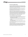
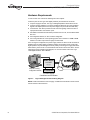
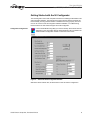
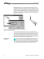
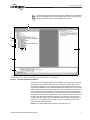
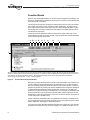
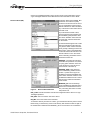
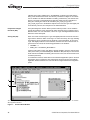
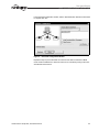
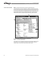
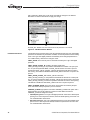
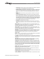
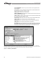
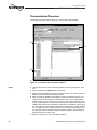
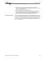
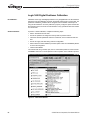
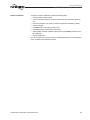
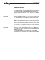
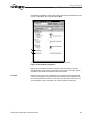
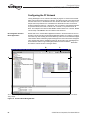
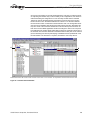
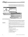
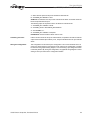
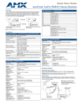
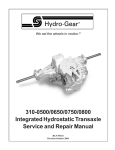
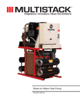
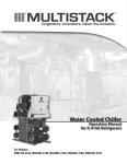
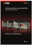
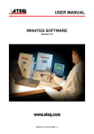
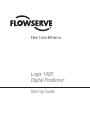
Logix 1400
Digital Positioner
Start-up Guide
Flow Control Division
Logix 1400 Digital Positioner Start-up Guide
Scope
This manual is provided for those users unfamiliar with fieldbus devices. It also provides
documentation to fill any gaps in information between fieldbus device user’s manuals
and configurator software manuals. This information is beneficial to those with a good
understanding of the new and emerging fieldbus technology but without experience
using it.
This document was written to be used specifically with the Logix 1400 digital positioner.
It is not meant to replace the Logix 1400 Digital Positioner User’s Manual, or be a complete guide to the fieldbus or NI Configurator software. This document will explain the
steps necessary to configure and bench-operate the Logix 1400 digital positioner. It
assumes the user has the positioner mounted to an actuator, tubed properly and with a
good air supply. This document references the NI Configurator (version 2.25) as the host
tool.
Definitions
AI block: Analog Input block. This block receives an analog signal and coverts it to a FF
signal.
AO block: Analog Output block. This function block produces an analog output signal.
This block controls the input to a transducer block.
Configurator: Software tool used to access data and configure FF devices
DD: Device Description. Files used by configurator software or other FF host, which
describes an FF device. DDs allow for custom manufacturer specific features to be
added to a FF device, and the host to have access to those custom features.
FF: FOUNDATION™ fieldbus. Communications protocol used in the Logix 1400 digital
positioner.
FINAL_VALUE: Fieldbus terminology for the positioner’s command signal.
Function Blocks: All FF device functions are divided into virtual function blocks. For
example, if the device is capable of performing PID control, a PID function exists.
FVPTB block: Flowserve Valve Positioner Transducer block. This block handles the
configuration, calibration and diagnostics for the Logix 1400 digital positioner.
Logix 1400 digital positioner: Flowserve’s FOUNDATION fieldbus two-wire valve positioner.
mA: Milliamperes
PID block: Proportional, Integral, Derivative control function block
RS block: Resource block. This block contains basic FF information and configuration
data
VDC: Volts, Direct Current.
2
©1999 Flowserve Corporation, Flow Control Division
Flow Control Division
Logix 1400 Digital Positioner Start-up Guide
FOUNDATION fieldbus Basics
The FOUNDATION fieldbus protocol is an all-digital, two-wire method of interconnecting
field devices. A traditional 4-20 mA analog loop calibrator can not be used with a Logix
1400 digital positioner. The positioner always receives its command signal from a digital
source. In essence, when configured, a FF loop becomes a local area network (LAN)
and the positioner receives it command over the network.
Because the Logix 1400 digital positioner is a two-wire device, existing wiring from a 420 mA application can be used. FF devices require 9-32 VDC power supply, and FF
power supply conditioner. (Just because the same wire can be used, it does not mean
the device is powered similar to other 4-20 mA devices.)
The different functions within an FF device are found in virtual function blocks. For
example, if a device is capable of performing PID control, the device will have a PID
function block. In an FF network any function block in one device can have a virtual connection to the function block of another device. This makes it possible to have any vendor’s transmitter PID function block connected to a Logix 1400 digital positioner analog
out function block, thus controlling the valve. Any combination of these virtual function
blocks is possible, regardless of who manufactures the devices. The NI Configurator
allows for easy graphical connection, or ‘wiring’ of the function blocks.
The Logix 1400 digital positioner contains four function blocks;
1. Resource block (RB). The RB contains basic FF information.
2. PID control block. This block is capable of performing PID control of a process. Honeywell designed the Logix 1400 digital positioner’s PID. Honeywell should be consulted for assistance in tuning this block.
3. Analog Out (AO). This function sends the command signal to the transducer block. It
can receive the signal from another function block, or be written to directly from the
Configurator.
4. Transducer block (FVPTB). This block converts the command signal
(FINAL_VALUE) to valve position. Positioner configuration, calibration and diagnostics are handled in this block.
The user should read all documentation that comes with any FF device. FF documentation can be obtained from the Fieldbus Foundation. The final section of this document
provides FF contact information.
To allow for product differentiation, the FF specification permits manufacturers to add
custom features to an FF device. For the host systems to take advantage of these custom features the manufacturer supplies a Device Description (DD). The DDs must be
installed correctly for the Configurator to take full advantage of a device’s functionality. A
later section details proper DD installation when using the NI Configurator.
©1999 Flowserve Corporation, Flow Control Division
3
Flow Control Division
Logix 1400 Digital Positioner Start-up Guide
Hardware Requirements
In order to have a FF network the following items are required:
FF device (such as the Logix 1400 digital positioner) and the DDs for the device
1. FF power supply 9-32 VDC. The Logix 1400 digital positioner draws about 23 mA.
2. FF power supply conditioner. The power conditioner allows for the communications
signals to be superimposed onto the power supply line (much like the HART filter).
3. FF terminator. This device prevents excess noise from getting onto the bus due to
improper termination of unused FF spurs.
4. NI Fieldbus card. National Instruments produces both a PC-AT, and a PCMCIA Fieldbus card.
5. NI Configurator software, or other vendor’s configurator.
6. PC running Windows 95 or NT operating system with a minimum of 16MB of RAM.
Pentium or Pentium II processor is highly recommended.
A PC running the Configurator, the power supply and the FF device are all connected in
parallel to the FF Power Supply Conditioner. Polarity is important, but the Logix 1400
digital positioner is protected against reverse polarity. Connecting the supply wires backwards will only cause a loss of communications and should not harm the device. The following figure shows a simple wiring diagram, for more information refer to the Logix
1400 Digital Positioner User’s Manual.
Power Supply
9-32 VDC
(+) (-)
Computer running
configurator software
FF Terminator
FF Power Supply
Conditioner and Terminator
Figure 1:
Logix 1400 Digital Positioner Wiring Diagram
NOTE: Contact information for the FF supply, conditioner and terminator can be found in
the last section of this document.
4
©1999 Flowserve Corporation, Flow Control Division
Flow Control Division
Logix 1400 Digital Positioner Start-up Guide
Getting Started with the NI Configurator
The NI Configurator comes with complete instructions for installing the NI Fieldbus card
and Configurator software. The instructions that came with the software should be followed carefully, ensuring that the software is installed and running properly. This document is not meant to cover NI Configurator software installation, or troubleshooting.
Flowserve does not offer technical support for the NI Configurator.
Configurator Configuration:
Launch the NI-FBUS Config utility (icon seen to the left). Select Port0. Click the
Edit button. In the Port window click the Advanced button. Fill in the fields in the
Advanced Stack Configuration window to match the screen below.
Figure 2:
Advanced Stack Configuration Window
With these values entered click, OK three times to save and exit the configuration.
©1999 Flowserve Corporation, Flow Control Division
5
Flow Control Division
Logix 1400 Digital Positioner Start-up Guide
DD Installation: While still in the Configuration utility select Board0, and click the
DD Info button. Take note of DD base directory field. This is the root directory for the DD
installation; any root directory is acceptable. The DDs must be installed in the correct
location in order for the Configurator to find them. From the directory listed in base (root)
directory field, create the sub-directory 464C53. In the 464C53 directory, create the subdirectory 0201. Install the DDs in the 0201 directory. Two files with the same four-digit
hexadecimal name should be found, along with different file extensions (XXXX.ffo and
XXXX.sym). These are the DDs.
B
A
C
A. DD base directory B. Directory Tree for DDs for example used C. Install DDs here
Figure 3:
DD Installation Windows
The two sub-directories created are specific to the Logix 1400 digital positioner. If
another device is to be attached to the bus, the correct sub-directory structure will have
to be created and the DDs installed. Always start the subdirectories in the directory
listed in the base DD directory field. Click OK in the DD info screen. More information
about how to create the directory structure for the DDs can be found in the Resource
Block section of this document. Whenever changes are made within Configuration Utility
the NI-FBUS must be restarted for the new settings to take effect.
Launching the NI
Configurator:
6
In order to run the Configurator software NI-FBUS (a fieldbus communications
driver must be running). To start the NI-FBUS double-click on the blue icon
shown on the left. Once running, the window will automatically minimize. Next
launch the NI_FBUS Configurator (icon with the NI logo and 3 squares seen at
the left). Click OK on the Add Links window. The Configurator window should
now open and the NI Fieldbus card should be listed in the window on the left.
©1999 Flowserve Corporation, Flow Control Division
Flow Control Division
Logix 1400 Digital Positioner Start-up Guide
Flowserve does not support the NI tools suite. If problems occur, check that all
steps in the installation manual were followed correctly and verify wiring and
setup. If the problem persists, contact National Instruments.
A
B
C
D
I
E
F
G
H
A. Transducer Block B. NI FF Card C. Logix 1400 Digital Positioner D. Function Blocks E. Function Block Tag Name
F. Function Block Type G. Main Configurator Window H. Status Window I. Help Window
Figure 4:
NI Configuration Set-up Window
Connect the Logix 1400 digital positioner to the fieldbus. One of the LEDs on the Logix
1400 digital positioner should start to blink. If not, verify wiring polarity and that the
power supply is plugged in. Once the NI card and Logix 1400 digital positioner are connected to the Fieldbus, the Logix 1400 digital positioner should show up in the NI Configurator’s main window (as seen above). Wait for the small hour glass icon that pops up
next to each device and function block to go away. Under the Logix 1400 digital positioner, four function blocks should be listed. Each function block should have the function
block tag name and type listed in apprentices. The four functions blocks are (AO)= Analog Out, (PID)= PID control, (RB)= Resource block, and (FVPTB)= Flowserve Valve
Positioner Transducer Block. If any of the blocks are listed as unknown (UKN) the DDs
are incorrect or not installed properly. If this occurred, try re-installing the DDs, and
restarting the NI-FBUS application.
NOTE: To view the transducer block, click the Transducer block icon.
©1999 Flowserve Corporation, Flow Control Division
7
Flow Control Division
Logix 1400 Digital Positioner Start-up Guide
Function Blocks
With the Logix 1400 digital positioner on the bus and NI Configurator now talking to the
positioner, configuration and calibration can take place. To do this, a brief understanding
of function blocks in necessary.
The function block’s tag name and type are listed under the device in the main Configurator window. Tag names can be changed for easier identification. To change the tag
name, right click the mouse cursor on the tag name. Select the Set Tag option. Type in
the new tag name, and click the Set button. Note that the block types (AO, PID, RB, or
FVPTB) remain unchanged.
To gain access to the parameters within a function block, simply double click on the
function blocks tag name in the main window. A pop-up window with several tabs similar
to the one below should now be seen.
A B
C D
E
F
G
H
I
J
A. Write (writes changes made within the block; must be clicked to apply parameter changes) B. Write All (writes all parameters to the
device) C. Read (reads the value of the selected parameter) D. Read All (reads all parameters from the function block) E. Clear (normally inactive) F. Refresh (redraws the screen) G. Customize Parameters (allows user to view custom sets of parameters)
H. Changes to one of three views I. Help J. Periodic Updates
Figure 5:
Function Block Parameter Window
Normally in a function block window, the All tab or the Custom tab is used. Click the Custom tab. Notice the Periodic Updates box in the upper left corner. The NI Configurator
does not constantly update the parameters within a function block window, so some of
the data may be stale. By checking the Periodic Update box the Configurator will attempt
to update the viewed parameters at the specified rate. On a busy bus, updating the
parameters may take longer than the specified rate. Once checked, the Parameters tab
under the other tabs in the Function Block window will be updated. Otherwise use the
Read button to verify that a parameter is correct. Do not assume that the value shown is
correct until a read or update is done.
The NI Configurator will display some of the parameters in decimal or hexadecimal format. To toggle between the two modes, move the mouse cursor inside the function block
window. Right click, and toggle the Hexadecimal option.
The next four sections detail what parameters must be set to within the Logix 1400 digital positioner’s function blocks to control the positioner on a Fieldbus network. It is not
8
©1999 Flowserve Corporation, Flow Control Division
Flow Control Division
Logix 1400 Digital Positioner Start-up Guide
meant to be a detailed description of the function blocks or their parameters. See the
Logix 1400 Digital Positioner User’s Manual and FF documentation for more details.
Resource Block (RB)
All function blocks have a MODE_BLK
parameter. Out Of Service (OOS)
means the function block is not executing. FF specifications require that the
Resource block be in Auto mode before
any of the other function blocks will exit
the OOS mode.
To put the Resource block in Auto,
open the Resource block window and
find the MODE_BLK parameter. Double-click on TARGET. Select Auto and
uncheck OOS. Click the Write button
on the tool bar.
An asterisk should appear next to TARGET, this indicates that the value has
not yet been written. Wait for the asterisk to go away, indicating the value has
been written. Click on the Read button
until the ACTUAL field reads Auto. The
Resource block is now in Auto mode.
Other noteworthy parameters found in
the Resource block are:
RESTART: Processor will reset both
the fieldbus and positioner card, similar
to cycling power. Selection of this will
cause the device to drop off the network and then come back up.
REVSION_ARRY: Three elements
exist in REVISION_ARRAY. Element
number 1 (closest to the top) is the
Fieldbus (Honeywell) Embedded Software version. Element number 2 is the
Fieldbus Stack Revision level. The final
element is the Positioner Embedded
Code revision.
Figure 6:
Resource Block Windows
MANUFAC_ID: This should always
equal a 0x00464c53 (4607059) (this is
Flowserve’s FF Manufacturer ID number). Converting this number to ASCII
will produce FLS.
DEV_TYPE: This will be 0x0202. This tells the Configurator that the device is a Logix
1400 digital positioner.
DEV_REV: This is the revision level of the device.
DD_REV: This is the revision level of the DDs.
To create the directory structure for a device, go to the DD base directory listed in the NIFBUS Config. In that directory create a sub-directory that matches the last six digits of
the hexadecimal number listed in MANUFAC_ID. Do not include the ‘0x’ hexadecimal
©1999 Flowserve Corporation, Flow Control Division
9
Flow Control Division
Logix 1400 Digital Positioner Start-up Guide
identifier. Next create a subdirectory in the MANUFAC_ID directory that matches the
DEV_TYPE hexadecimal numbers. This directory should be four digits. Do not include
the ‘0x’ identifier. The DDs are installed in the DEV_TYPE directory. Two exist for each
device. Their name is a hexadecimal four-digit name made from the combination of
DEV_REV and DD_REV with the file extensions [dev_rev|dd_rev].sys and
[dev_rev|dd_rev].ffo. Go to the Windows Explorer tool to see the Logix 1400 digital positioner directory structure, and compare it to the data listed above.
Proportional Integral
Derivative (PID)
Honeywell designs this function block to perform PID loop control. It is not needed to
operate the positioner. Some of its features will be discussed in the Configuring the FF
Network section. For more information, refer to the Logix 1400 Digital Positioner User’s
Manual or contact Honeywell.
Analog Out (AO)
When in an active control loop, the Logix 1400 digital positioner receives its command
signal into the AO block. When not running in an active control loop, the Logix 1400 digital positioner can be controlled from the AO block or the FVPTB block. To control the
Logix 1400 digital positioner from the AO block, the block must be in manual mode. To
get this block out of OOS, set the following parameters in the AO block.
•
•
CHANNEL = 1
SHED_OPT = NormalShed_NormalReturn
Click the write button to apply. Use Read or Periodic Update to verify the changes have
taken place. Now try to set the MODE_BLK: TARGET to Man (manual). If it won’t exit the
OOS mode and CHANNEL and SHED_OPT are both correct, the AO block needs to be
scheduled (executed).
To schedule the AO block, double-click the Function Block Application option in the main
(left) window of the Configurator. Click and drag the AO block into the Function Block
Application Window. Next from the menu bar select Configure/Download Configuration
option.
C
A
B
A. Click to open Function Block application window B. Drag AO function block into the Function Block Application Window C. Function
Block Application Window
Figure 7:
10
Function Block Window
©1999 Flowserve Corporation, Flow Control Division
Flow Control Division
Logix 1400 Digital Positioner Start-up Guide
In the Download Configuration window, click the Download button. Wait for the download
to complete then exit.
Figure 8:
Download Configuration Window
Repeat the steps to put the AO block into manual mode. With the AO block in MAN
mode and the FVPTB block in AUTO the valve can be controlled by writing to the OUT:
VALUE within the AO block.
©1999 Flowserve Corporation, Flow Control Division
11
Flow Control Division
Logix 1400 Digital Positioner Start-up Guide
Transducer Block (FVPTB)
NOTE: To view the transducer block, first click the Transducer Block icon.
The transducer block is where all configuration, calibration and diagnostics are set up,
and read. Due to the large amount of data that can be accessed in the transducer block,
the custom view option should be used and the parameters of interest selected. To do
this, choose the Custom tab in the FVPTB Window and click the Custom button on the
tool bar. Check the items to view in the pop-up selection menu. Check the Periodic
Update button to have the Configurator update the data every couple of seconds.
B
A
C
A. Periodic Update Box B. Custom Parameters C. Selection Menu
Figure 9:
Transducer Block Window
If the positioner is to be controlled by the AO block, the FVPTB block must be in Auto. If
the positioner is to be controlled by the FVPTB the AO block must be in OOS and
FVPTB in OOS. To move the valve, write to FINAL_VALUE: VALUE.
12
©1999 Flowserve Corporation, Flow Control Division
Flow Control Division
Logix 1400 Digital Positioner Start-up Guide
Logix 1400 Digital Positioner Configuration
Configuration of the Logix 1400 digital positioner is done almost exclusively in the transducer block (FVPTB).
Open the transducer block (FVPTB) window by double-clicking its tag in the main NI
Configurator window. The FVPTB MODE_BLK: TARGET parameter must be set to OOS
in order to do any configuration.
Due to the large number of parameters in the FVPTB configuration is easiest under the
Custom tab. Use the Custom Config button to select parameters to be viewed or modified. Check the Periodic Update box to ensure that the data being viewed is current.
The following table summarizes basic configuration of a Logix 1400 digital positioner on
a 25 square-inch actuator and linear valve.
Table 1: Logix 1400 Digital Positioner Parameters
Default
Value
Parameter
MODE_BLK:TARGET
Auto
Function
Determines the mode of the function block.
FINAL_VALUE
No default
Command going to positioner before characterization, soft stops, or MPC.
FINAL_VALUE_CUTOFF_HI
110%
This will saturate the actuator in an open position, if FINAL_VALUE
becomes greater than the cutoff value.
FINAL_VALUE_CUTOFF_LO
1%
This will saturate the actuator in a close position, if FINAL_VALUE
becomes less than the cutoff value. This is the same has the Minimum
Position Cutoff feature of the Logix 1200 digital positioner. The new terminology matches FF terminology.
FINAL_POSITION_VALUE
Dynamic
Actual stem position in percent of stroke.
DAC_PERCENT
Dynamic
DAC output in percent.
CONTROL_FLAGS
Advanced
Model
Used to tell positioner type of actuator and characterization to use.
GAIN_UPPER
2
Maximum proportional gain used.
GAIN_LOWER
1
Minimum proportional gain used.
GAIN_MULT
0.05
Adjust the rate of change between GAIN_UPPER and GAIN_LOWER.
Same as in the Logix 1200 digital positioner.
IGAIN
10
Integral gain.
IL_OFFSET
30-70%
DAC value to hold spool in a null position. This value is automatically
adjusted during a stroke calibration procedure.
SOFTSTOP-HIGH
110%
Software upper stroke limit.
SOFTSTOP_LOW
-10%
Software lower stroke limit.
PRESS_UNITS
Psi
Units pressure sensors reading are expressed in.
TEMP_UNITS
Degrees F
Units temperature is expressed in.
To set the FVPTB in OOS mode, double-click on MODE_BLK: TARGET, in the pop up
box check the OOS box. Click the Write button. With the block mode is set to OOS
(MODE_BLK: ACTUAL = OOS), editing the parameters is now permitted. To change or
©1999 Flowserve Corporation, Flow Control Division
13
Flow Control Division
Logix 1400 Digital Positioner Start-up Guide
edit a parameter, double-click on the value, and make the changes in the Edit box.
Remember to click the Write button to apply the change.
A
A. MODE_BLK: TARGET must have OOS selected to edit parameters in the FVPTB
Figure 10: FVPTB Parameter Window
Parameter Definitions:
The following list summarizes some of the key parameters within the Logix 1400 digital
positioner. For definitions of parameters not listed, use the help window in the NI Configurator. The Logix 1400 digital positioner automatically stores changed parameters in
non-volatile memory whenever the change is made.
FINAL_VALUE: This is the set point or command received by the Logix 1400 digital
positioner.
FINAL_VALUE_CUTOFF_HI: If FINAL_VALUE is greater than
FINAL_VALUE_CUTOFF_HI, the positioner will saturate the actuator in an open position. A 1 percent hysteresis added, so FINAL_VALUE must be more than 1 percent
smaller than FINAL_VALUE_CUTOFF_HI before the positioner will allow the valve to
start closing. This feature is disabled in SOFTSTOP_HIGH is less than or equal to 100
percent
FINAL_VALUE_CUTOFF_LO: If FINAL_VALUE is less than
FINAL_VALUE_CUTOFF_LO, the positioner will saturate the actuator in a closed position. A 1 percent hysteresis is added, so FINAL_VALUE must be more than 1 percent of
FINAL_VALUE_CUTOFF_LO before the positioner will allow the valve to start opening.
This feature is disabled in SOFTSTOP_LOW is less than or equal to 0 percent
FINAL_POSITION_VALUE: This is the valve’s stem position as sensed by the positioner. This value is always reported in percent of stroke.
CONTROL_FLAGS: Eight options exist under CONTROL_FLAGS. Each option has a
significant effect on how the positioner controls the valve. Make sure that the
CONTROL_FLAGS is configured correctly.
14
•
Quick Opening Curve: The Logix 1400 digital positioner comes with a default quick
opening curve. If this response is desired, check the Quick Opening Curve and Custom Characterization Active boxes
•
Equal Percent Curve: The Logix 1400 digital positioner comes with a default equal
percent curve. If this response is desired, check the Equal Percent Curve and Custom Characterization Active boxes.
©1999 Flowserve Corporation, Flow Control Division
Flow Control Division
Logix 1400 Digital Positioner Start-up Guide
•
Actuator Type: Check this box only when the positioner is mounted on a single acting type actuator. This will disable the second pressure sensor.
•
Positioner Model: This parameter is automatically set at power-up. It tells the positioner if it is an advanced (pressure sensors) model or standard (no pressure sensors). If the user wishes to over-ride the Auto Model Detect feature, consult the
factory.
•
Actuator Style: Check this box only if the positioner is mounted on a rotary type
actuator.
•
Custom Characterization Active: Check this box if the user wishes to have the
FINAL_VALUE parameter characterized. If the Quick Opening or Equal Percent box
is also checked the positioner will use a factory defined curve. If only Custom Characterization Active is checked a user-defined curve will be used. Note that when this
box is checked the curve can not be changed. If the user wishes to use a different
curve, or edit the custom curve, the user must first uncheck this box.
•
•
Fail Position: Currently this has no function.
Air Action: Check this box only if the actuator is tubed to be ATC (Air-To-Close)
After configuring CONTROL_FLAGS, remember to click the Write button to apply the
values.
GAIN_UPPER: The Logix 1400 digital positioner uses a special gain algorithm. The
proportional gain increases with a decrease in error. This allows for maximum resolution
and speed. GAIN_UPPER is the upper limit to proportional gain.
GAIN_LOWER: The Logix 1400 digital positioner uses a special gain algorithm. The
proportional gain increases with a decrease in error. This allows for maximum resolution
and speed. GAIN_LOWER is the lower limit to proportional gain.
GAIN_MULT: The Logix 1400 digital positioner uses a special gain algorithm. The proportional gain increases with a decrease in error. This allows for maximum resolution
and speed. GAIN_MULT adjust the transition rate between GAIN_UPPER and
GAIN_LOWER.
IGAIN: In addition to proportional gain the Logix 1400 digital positioner used integral as
well. This in the integral gain setting. Typically this is set to 10.
IL_OFFSET: This parameter tells the positioner where the spool valves ‘null’ position is.
This value is set during a stroke calibration procedure, and typically requires no further
adjustments.
CMD_USED: This is the set point or command to which the positioner is controlling.
After FINAL_VALUE is acted on by Characterization, Softstops and
FINAL_VALUE_CUTOFF, CMD_USED reports the modified or used command value.
CALIBRATE: This parameter initiates Calibration. Three types of calibration are available: stroke, pressure sensors (advanced models only) and stroke time test. Stroke time
test will measure the stoke speed of the actuator from a 1 percent to 99 percent position,
and from 99 percent to 1 percent. To learn more about calibration refer, to the Calibration section of this document.
PRESS_CAL: Before doing a pressure sensor calibration, enter the supply pressure
being used (in units expressed by PRESS_UNITS).
SOFTSTOP_HIGH: Software-imposed stroke limit. The positioner will not allow the
valve to open beyond the value shown in this parameter.
SOFTSTOP_LOW: Software-imposed stroke limit. The positioner will not allow the valve
to close beyond the value shown in this parameter.
CYCLE_COUNTER: : This parameter counts the number of cycles that have occurred.
©1999 Flowserve Corporation, Flow Control Division
15
Flow Control Division
Logix 1400 Digital Positioner Start-up Guide
CYCLE_DEADBAND: In order for a cycle to be counted, it must be greater than the
value in this field.
CYCLE_LIMIT: If CYCLE_COUNTER exceeds this value, the yellow LED will start to
blink and a warning generate in TRAVEL_FLAGS.
TRAVEL_ENG: Total distance the valve traveled.
TRAVEL_DEADBAND: Amount in percent of stroke the valve must move for the movement to be added to TRAVEL_ENG.
TRAVEL_ALERT: If TRAVEL_ENG exceeds this value, the yellow LED will start to blink
and a warning generated in TRAVEL_FLAGS.
STROKE_ENG: Stoke length of valve. This value is used to calculate TRAVEL_ENG.
TRAVEL_UNITS: Units of measure used to calculate TRAVEL_ENG.
PRESS_UNITS: Units of measure that pressure sensor readings are expressed in.
TEMP_UNITS: Units of measure that temperature is expressed in.
FAIL_MODE: Should a communication loss occur between the fieldbus card and positioner card this parameter sets the fail-mode of the valve. Nothing selected will cause
the positioner to hold the last known command should a communication loss occur.
A
B
C
D
E
F
G
A. Selection to use quick-opening characterization curve B. Selection to use equal-percent characterization curve C. Actuator type
D. Positioner model type E. Actuator style F. Characterization active; if the quick-open or equal-percent option are selected, that curve
will be used. If neither is selected, the characterization curve will be user-defined G. Air action of actuator
Figure 11: CONTROL_FLAGS Window
16
©1999 Flowserve Corporation, Flow Control Division
Flow Control Division
Logix 1400 Digital Positioner Start-up Guide
Stroke Characterization
In addition to three pre-defined and embedded characterization curves, the Logix 1400
digital positioner has a 21-point custom stroke characterization feature. This allows the
user to define a unique set of operating parameters customizable to his process conditions.
Table 2: Transducer Block Characterization Parameters
Parameter
MODE_BLK
Description
Value — Meaning
Comments
Permitted Modes:
The operating
mode of the trans- Auto — Auto (target
ducer block
mode)
The transducer
block must be out
of service before
the user can edit
OOS — Out Of Service or change characterization.
CONTROL_FLAGS Byte values which
select positioner
operation features
1 Quick Opening
Curve*
Loads factorydefined QO curve
as custom curve.
2 Equal Percent
Curve
Loads factorydefined equal percent curve as custom curve.
3 Actuator Type
4 Advanced Model
5 Rotary Actuator
Gain
6 Custom Characterization Active
Activates custom
curve. If ‘Off’,
response is
‘Linear.’
7 Fail Position TBD
8 Air Action
CURVEX
Numeric X value
array for custom
point.
X-axis value for custom Pair each X-value
stroke characterization with correspondpoint. Range -10 to 110 ing Y-value to
define the desired
(1x21 array points)
point.
Values must be in
ascending (or
equal) order.
CURVEY
Numeric Y value
array for custom
point.
Y-axis value for custom
stroke characterization
point. Range -10 to 110
(1x21 array points)
* Must not be selected if a custom curve is to be created or edited.
©1999 Flowserve Corporation, Flow Control Division
17
Flow Control Division
Logix 1400 Digital Positioner Start-up Guide
Characterization Procedure
The following procedure outlines setting up a custom stroke characterization.
A
C
B
A. X-axis variables (21) B. Y-axis variables (21) C. Control Flags window
Figure 12: Custom Stroke Characterization Window
Steps:
18
1. Verify the process is in a safe condition and that the valve may be taken out of service.
2. Put the Transducer block MODE_BLK out of service.
3. Make sure that Quick Opening Curve, Equal Percent Curve, nor Custom Characterization Active are selected in CONTROL_FLAGS.
4. Enter the values for CURVEX and CURVEY to define the desired response. Care
must be taken to assure that each CURVEX value has the correct corresponding
CURVEY value. The user may choose any number in the range to define the curve.
The 21 CURVEX points do not need to be evenly spaced, if so desired. However, the
CURVEX values must be in ascending (or equal) order. The CURVEY points may be
any value in the range, ascending or descending. The response is a linear interpolation, or straight-line, response between points. All 21-points must be defined. (i.e. If
only five point sets were needed to define the desired operation, the remaining 16
points would need to be set to 110.)
5. Write the changes to the Logix 1400 digital positioner.
©1999 Flowserve Corporation, Flow Control Division
Flow Control Division
Logix 1400 Digital Positioner Start-up Guide
6. Activate the custom curve by selecting Custom Characterization Active in
CONTROL_FLAGS. (NOTE: Make sure that neither Quick Opening Curve nor Equal
Percent Curve has been selected.)
7. Write the changes to the Logix 1400 digital positioner.
8. Verify the proper operation of the stroke response by incrementally writing values to
FINAL_VALUE. (The Resource block must also be OOS first.) CMD_USED,
FINAL_POSITION_VALUE, and the valve response should track the desired curve.
9. Return the valve to service by returning both MODE_BLKs back to Auto.
Characterization Retention
Once a custom curve has been loaded into the Logix 1400 digital positioner’s memory it
is retained in the EPROM until it is either edited or replaced. Turning Custom Characterization Active on or off now selects between a linear response (Off), or the new custom
curve (On). If either of the other two factory curves is selected, it will overwrite the custom curve in RAM only. The custom curve will automatically be activated again when the
factory curve is deselected.
©1999 Flowserve Corporation, Flow Control Division
19
Flow Control Division
Logix 1400 Digital Positioner Start-up Guide
Logix 1400 Digital Positioner Calibration
Re-Cal Button:
Calibration of the Logix 1400 digital positioner is very straightforward. The Re-Cal button
will perform a stroke calibration procedure, but the DIP switches are no longer used. The
parameter CONTROL_FLAGS must be configured over the fieldbus network prior to
using the Re-Cal button. Once the positioner is properly configured, press and hold the
Re-Cal button for five seconds. The Re-Cal button is only operational when the FVPTB
is in OOS mode.
Stroke Calibration:
To perform a stroke calibration, complete the following steps:
•
•
•
Set the Transducer block to OOS.
•
•
Ensure air supply and valve tubing matches configuration.
•
Ensure the positioner is configured correctly. Refer to previous section.
Check the Periodic Update box under the Custom tab, in the Transducer block window.
Select Perform a stroke calibration procedure option under the CALIBRATE parameter in the NI Configurator.
Click the Write Button.
The valve should now go closed, open, then to a mid-stroke position for a few seconds.
CALIBRATE will return to normal operation at the completion of the calibration process
Figure 13: Calibration Window
20
©1999 Flowserve Corporation, Flow Control Division
Flow Control Division
Logix 1400 Digital Positioner Start-up Guide
Pressure Calibration:
To perform a pressure calibration complete the following steps:
•
•
•
•
•
•
•
•
Set the Transducer block to OOS.
Check the periodic update box under the Custom tab, in the Transducer Block window.
Ensure the positioner is an advance model (see parameter CONTROL_FLAGS).
Ensure air supply.
Set PRESS_CAL to air supply pressure value.
Set PRESS_UNITS to the proper pressure units
Select Perform Pressure Calibration option under the CALIBRATE parameter in the
NI Configurator.
Click the Write button.
The valve should now go closed, then open. CALIBRATE will return to normal operation
at the completion of the calibration process.
©1999 Flowserve Corporation, Flow Control Division
21
Flow Control Division
Logix 1400 Digital Positioner Start-up Guide
Controlling the Valve
The Logix 1400 digital positioner (or the valve position) can be controlled with one of
three basic methods. The first method is to control the valve directly from the Transducer
block (FVPTB). When setting up and configuring the positioner, this is a logical method
to use. The second method in through the AO block. This method will verify that the
positioner is receiving a command from the AO block. This method can be used when
setting up the FF network or when troubleshooting the network. The final method is to
put the positioner in a FF network and receive its command signal from a function block
in a device on the loop.
From the XD:
Control from the FVPTB is the easiest to set up. The FVPTB and AO must both be set to
OOS. This can be accomplished by two methods: The simplest method is to put the
Resource block in OOS. (Whenever the Resource block is in OOS mode, all other blocks
will go to the same mode.)
NOTE: This could cause problems if the device has any function blocks being used in an
FF network, because all function blocks will go to OOS mode, and stop executing.
The second method is to have the FVPTB and AO OOS open their respective windows
in the Configurator and set MODE_BLK: TARGET to OOS.
Once the two block are set to OOS write, in percent of stroke, the new valve position in
the FVPTB’s FINAL_VALUE: VALUE parameter field and click the Write button. The
positioner will move the valve to that position.
From the AO:
Control from the AO block is almost as simple. The AO must be set to MAN (manual)
mode, and the FVPTB must be in Auto. To get the any of the function blocks out of OOS
the RB must be set to Auto.
To get the AO block into MAN mode two parameters must be set. The CHANNEL
parameter must be set to 1 and the SHED_OPTS parameter to anything but initialized.
22
©1999 Flowserve Corporation, Flow Control Division
Flow Control Division
Logix 1400 Digital Positioner Start-up Guide
(NormalShed_NormalReturn is the typical setting.) After these two parameters are properly set, the AO MODE_BLK can be changed to MAN.
A
B
A. CHANNEL must be set to 1 B. SHED_OPT cannot be set to Uninitialized
Figure 14: Manual Mode Configuration
With the AO now in MAN mode set the FVPTB to Auto mode. Writing to the OUT:
VALUE parameter, in the AO block, will control the valve position. The FINAL_VALUE
parameter in the FVPTB will now track the AO’s OUT: VALUE.
FF Control:
Fieldbus control is much more complicated. The FF network must be configured with
some type of transmitter (AI) and control function block (PID). The configuration must
then be downloaded to the devices. For this reason, the next section will cover FF network configuration. Valve control within a FF control loop will be covered here.
©1999 Flowserve Corporation, Flow Control Division
23
Flow Control Division
Logix 1400 Digital Positioner Start-up Guide
Configuring the FF Network
The big advantage to an FF network is the ability to program or connect function block
within a device to another FF device on the bus. This allows process control to be moved
from the control room, to the field devices. This section will outline how to setup a very
simple control loop. Reference to a standard FF AI block will be made. The AI block
must be configured to output 0 – 100 percent. The AI could be in a temperature transmitter, pressure sensor, flow meter, 4-20 mA to FF converter, or any device with an AI
block. The example in this section used SMAR’s IF302 4-20mA to FF converter. Details
into the setup of the SMAR AI are not included in this document.
NI Configurator Function
Block Application:
Double-click on the Function Block Application selector in the main window of the Configurator. This will open the Function Block Application window. To configure or create a
FF control loop, click and drag the function block tag name into the Function Block Application window. When released a graphical wiring block for the function block will appear
in the window. Drag into the application window an AI block the Logix 1400 digital positioner PID block and the Logix 1400 digital positioner AO block. Click the Wire button
and wire the network as seen in the figure below.
B
A
C
D
E
A. Function Block Application Selector B. Loop Time Box C. Wire button D. Function Block Application Window E. Function Block
Wiring display
Figure 15: Function Block Wiring Window
24
©1999 Flowserve Corporation, Flow Control Division
Flow Control Division
Logix 1400 Digital Positioner Start-up Guide
Once the function blocks are virtually wired together the next step is to adjust to schedule. Adjusting the schedule may not be necessary for all configurations, but it seems to
make downloading the configuration run more smoothly. Double-click the Schedule
Selector to open the Schedule window (seen below). Execution time of the function
blocks is shown in blue. Scheduled network time is shown in red. Click and slide the
function blocks to allow a small amount of time between each. The Configurator schedules execution immediately after the previous block finishes execution. Next adjust the
loop time. Scroll to the end of the schedule and note the total loop execution time. Go
back to the Function Block Application window and change the value in the Loop Time
box. Make loop time at least 100ms greater than the total sum of execution times seen in
the schedule. This extra time allows for unscheduled tasks to take place on the network
(such as detecting new devices) and keeping Link Masters devices updated with a live
list and schedule. The shorter the Loop Time, the faster the control loop will run.
A
B
C
A. Schedule Selector B. Function block execution time as seen on the schedule C. Gap between function block execution time
Figure 16: Schedule Selector Window
©1999 Flowserve Corporation, Flow Control Division
25
Flow Control Division
Logix 1400 Digital Positioner Start-up Guide
With the function blocks programmed and the schedule adjusted, the project can be
downloaded. Click the Download Project button on the toolbar. When the download
screen pops up, click the Link Masters button. In the Link Masters area make sure only
the NI card is selected. This is only to make the download feature run more smoothly.
C
A
B
A. Download status bar B. Ensure the NI Card is selected C. Link Masters button
Figure 17: Download Projects Windows
Close the Network Parameters window. Click the Download button. The status bar will
show progress of the download. The download can take several minutes. Close the window once the download is complete. The Network in now programed or configured.
Function Block
Configuration:
The next step is to configure the function blocks to run automatically. Remember that the
Resource block mode for both devices must be set to Auto.
AI Block: The AI mode must be set to Auto, and the output in terms of 0 – 100 percent.
The output of the AI block will be passed directly to the valve positioner in this configuration. Consult the Logix 1400 Digital Positioner User’s Manual for configuration instructions.
PID Block: The Logix 1400 digital positioner’s PID block was designed by Honeywell.
This section will describe how to pass an input directly to the PID’s output. For more
information on how to configure the PID, consult the Logix 1400 Digital Positioner User’s
Manual or Honeywell.
Do the following to set up the PID block:
1. Set MODE_BLK: TARGET to OOS.
2. Set SHED_OPTS to NormalShed_NormalReturn.
3. Set BYBASS to Off.
4. Set CONTROL_OPTS to Direct Acting.
5. Set MODE_BLK: TARGET to Man.
6. Read the Value in IN: VALUE.
26
©1999 Flowserve Corporation, Flow Control Division
Flow Control Division
Logix 1400 Digital Positioner Start-up Guide
7. Write value the previous step to SP:VALUE and OUT:VALUE.
8. Set MODE_BLK:TARGET to Auto.
AO Block: The AO block must be put into Cascade mode. When in Cascade mode the
block’s output will tracks its input.
The following steps are required to set the AO block into cascade mode.
1. Set MODE_BLK: TARGET to OOS.
2. Set SHED_OPTS to NormalShed_NormalReturn.
3. Set CHANNEL to 1.
4. Set MODE_BLK: TARGET to Cas|Auto.
FVPTB Block: Set the transducer block mode to Auto.
Controlling The Valve:
If all the function blocks are set up as outlined above, the positioner should now tack the
output of the transmitter (the AI block). If not, verify that the blocks are set up as outlined
above.
Saving the Configuration:
This configuration can be saved by the Configurator. This is recommended if the PC is
going to be disconnected or removed from the FF network. The Configurator is not able
to reconstruct the graphical wiring diagram, so reconstructing a pre-configured network
is extremely difficult. By saving the configuration, the graphical wiring diagram is saved.
Saving is done upon exit from the Configurator software.
©1999 Flowserve Corporation, Flow Control Division
27
Flow Control Division
Logix 1400 Digital Positioner Start-up Guide
Initiating a Valve Signature
A feature of the Logix 1400 digital positioner is the ability to capture and store a valve
diagnostic signature in the positioner’s volatile RAM. A signature is the collected data
response of the valve to a pre-defined set of operating conditions. This stored data can
later be uploaded to the host system for analysis of potential problems. By comparing a
baseline signature (when the valve is new) to subsequent signatures at later times, a
rate of change can be tracked which can help predict possible faults in the valve before
they happen. This is called ‘predictive maintenance’.
NOTE: The purpose of the positioner is to act as the data acquisition device for the signature. Analysis of the data is not done on the device, but in the supervisory system.
System Preparation
WARNING: By definition, the collection of the signature requires the unmanaged operation of the positioner. Therefore, the process must be in a safe
operating mode where unexpected movement of the valve will not cause a
hazardous condition.
Before a valve signature can be run, the Transducer block must out of service.
Table 3: Transducer Block Signature Parameters (1 of 2)
Parameter
MODE_BLK
Description
The operating mode of
the transducer block
Value — Meaning
Permitted Modes:
Auto — Auto (target mode)
OOS — Out of service
SIG_FLAGS
Comments
The transducer block must be in
the OOS mode to perform a signature
Select the desired signature
options and then make sure the
signature parameters are set to the
1 - STEP_RAMP selects which desired operation before beginning the signature.
type of signature is desired.
Select for ramp signature.
Byte values that select 0 - VALVE INIT initializes valve
which signature options for signature capture. Readare used
only
2 - SIG_COMPLETE sets status byte when the signature has
been completed, Read-only
4 - PRESS_MEAS selects if
actuator pressure readings are
desired as part of the signature.
Select for readings
5 - BEGIN_SIG set to initiate
the signature routine.
SIG_START
Beginning position point -10% to 110% position range
(%) for signature
Set higher than the stop position
for a valve closing signature.
SIG_STOP
Ending position point
(%) for signature
-10% to 110% position range
Set lower than the starting position
for a closing signature
RAMP_RATE*
Desired rate (% per
minute) for ramp
%/Min. (Minimum value is 1.0.)
Typically this is set to 100. Very
long times could result in completely filling the 10K RAM buffer.
Can only be set when
STEP_RAMP in SIG_FLAGS has
been selected.
28
©1999 Flowserve Corporation, Flow Control Division
Flow Control Division
Logix 1400 Digital Positioner Start-up Guide
Table 3: Transducer Block Signature Parameters (2 of 2)
Parameter
Description
Value — Meaning
Comments
SAMPLE_TIME
Data acquisition time
between samples
Seconds. Range 0.1 to 2.55.
Set to a valid value before running signature. Typically 0.1
Determines the number of data
points stored in the signature.
STEP_TIME*
Delay time after step
Seconds. Range 0-650.0 Typically set to 0.1
Allows settling time to capture
valve response to the step. Can
only be set when STEP_RAMP in
SIG_FLAGS is not selected.
SIG_INDEX
Pointer used for data
transfer
Write the desired packet value.
Writing a value between 1 and the
max number shown in
SIG_COUNTER moves that packet
of data into the SIG_DATA array for
retrieval.
SIG_COUNTER
Indicates number of
data points collected
Increments by 1 as each data
packet is collected
SIG_DATA
Array for the storage
and transfer of signature data
Order of data is:
Command (%)
Position (%)
Port 2 pressure
Port 1 pressure
STROKE_TSTPSI
Supply pressure in psi
for stroke test
150 psi max.
STROKE_OPENTIM
Stroking time during
opening
Seconds
Determined during the last stroke
calibration where the Step Time
Test option was ran
STROKE_CLOSEDTIM
Stroking time during
closing
Seconds
Determined during the last stroke
calibration where the Step Time
Test option was ran
* Special Note: Because of the internal database size limit of 10K within the fieldbus device, the values for
RAMP_RATE or STEP_TIME may be recalculated to the most reasonable value to allow using the database. The
new value will appear in the parameter after the desired one is written. This is done to prevent accidental overflow
of the database.
The database may possibly overflow because of timing constraints. If this should happen, SIG_COMPLETE will
not appear, but BEGIN_SIG will be turned off. BLOCK_TEST element 6 will be set to 10 (0x0a) as an error indication. Since this does not affect operation of the positioner itself, no actual error will be reported over fieldbus.
©1999 Flowserve Corporation, Flow Control Division
29
Flow Control Division
Logix 1400 Digital Positioner Start-up Guide
Signature Procedure
The following steps are an example of how to initiate a ramp signature capture.
A
A. Signature Flags box
Figure 18: Ramp Signature Window
1. Make sure the process is in a safe condition and notify the control room that the
valve will temporarily be taken off-line.
2. Verify preparedness to proceed.
3. Put the Transducer block MODE_BLK out of service.
4. Set SIG_START to desired value.
5. Set SIG_STOP to desired value.
6. Set SAMPLE_TIME to desired value. (Typically 0.1)
7. In SIG_FLAGS, select; STEP_RAMP, PRESS_MEAS.
8. Write values to the Logix 1400 digital positioner.
9. Set RAMP_RATE to desired value (typically 100).
10. Write value to the Logix 1400 digital positioner.
11. In SIG_FLAGS, select BEGIN_SIG.
12. Write value to the Logix 1400 digital positioner.
30
©1999 Flowserve Corporation, Flow Control Division
Flow Control Division
Logix 1400 Digital Positioner Start-up Guide
13. The valve will stroke to the beginning position (as defined by SIG_START) and will
begin ramping to the desired ending position, as defined by SIG_STOP. Notice that
SIG_COUNTER will increment while this takes place. (Typically approximately 670
data sets will be collected with the above settings and full stroke of the valve. Exact
numbers will vary.)
14. SIG_FLAGS indicates SIG COMPLETE.
15. Return the MODE_BLK to Auto.
16. Notify control room the valve is back on-line.
The stored signature will remain in the Logix 1400 digital positioner volatile RAM until
the either the unit is powered down, or another signature is taken which overwrites the
previous one.
STEP SIGNATURE
If a step signature was desired, do not select STEP_RAMP in SIG_FLAGS, and then
set the STEP_TIME prior to selecting BEGIN_SIG.
Collection of Stored
Signature
The collection of the stored signature is accomplished by the host system. It is not part
of the device. See host system programming.
A simple utility using National Instruments NIFBUS is available from Flowserve for
retrieving a signature file. This file is stored in a text format that can be imported into
other programs for plotting and analysis.
Contact Flowserve for more details.
Contact Information
Fieldbus Foundation
9390 Research Blvd.
Suite 11-250
Austin, TX 78759
512-794-8890 voice
512-794-8893 fax
www.fieldbus.org/information/
RELCOM Inc. (FF power conditioners and terminators)
2221 Yew Street
Forest Grove, OR 97116
800-383-3765 voice
503-357-0491 fax
E-mail: [email protected]
National Instruments (Configurator software)
6504 Bridge Point PKWY
Austin, TX 778730-5039
512-794-0100 voice
Support number: 512-794-5678
www.natinst.com
[email protected]
©1999 Flowserve Corporation, Flow Control Division
31
FCD VLAMN146-00a
©1999 Flowserve Corporation. Flowserve Corporation, Flow Control Division