1
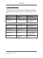
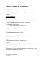
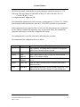
ControlNet ISA Interface Adapter
(Catalog No. CN-1000)
Installation Guide
1850 Research Drive
Suite 300
Troy, Michigan 48083
TEL:
FAX:
Web:
(248) 524-3890
1-888-PYRASOL
(248) 524-3899
www.pyramid-solutions.com
Pyramid Solutions
Table of Contents
1. OVERVIEW ..................................................................................................................................................................1
2. FEATURES ....................................................................................................................................................................2
3. CN-1000 DIAGRAM...................................................................................................................................................3
4. CONFIGURATION......................................................................................................................................................4
4.1 BASE M EMORY A DDRESS......................................................................................................................................4
4.2 8/16 BIT HOST A CCESS SELECT ...........................................................................................................................6
4.3 MAC ID....................................................................................................................................................................6
4.4 INTERRUPT CONFIGURATION ..............................................................................................................................7
5. ADDITIONAL PORTS/JUMPERS...........................................................................................................................8
5.1 GENERAL REGISTER(DEBUG) PORT .....................................................................................................................8
5.2 ISP PORT ..................................................................................................................................................................8
5.3 INT 1 JUMPERS........................................................................................................................................................8
6. INSTALLATION..........................................................................................................................................................9
7. STATUS INDICATOR LIGHTS............................................................................................................................. 10
APPENDIX A - RUNNING THE CARD DIAGNOSTICS ....................................................................................... 11
APPENDIX B - ERROR CODES ................................................................................................................................ 16
APPENDIX C - COMPATIBLE SOFTWARE.......................................................................................................... 17
APPENDIX D - FIRMWARE UPDATES ................................................................................................................... 18
APPENDIX E - WARRANTY INFORMATION....................................................................................................... 19
Document Number CN1000-0198-001
May 13, 1999
i
Pyramid Solutions
Contents Included in Package
The package that you ordered should include the following items:
Item Number
Quantity
Description
1
2
3
1
1
1
CN-1000 Card
CN-1000 Installation Guide
CN-1000 Utility disk containing diagnostic program, flash
update utilities and readme file
Document Number CN1000-0198-001
May 13, 1999
ii
Pyramid Solutions
Handling the Card
Warning: The CN-1000 card contains electronic components which are
highly sensitive to electrostatic discharge (ESD). Handling the card without
the proper ESD protection can cause internal damage to the card. Please
take the following precautions to protect against ESD damage:
•
•
•
Always store the card in its protective bag when not in use.
Before handling the card, be sure to wear a static strap and touch a
grounded object to release any built-up static charge.
Never touch the backplane connector or interface connector pins of
the CN-1000 card.
Document Number CN1000-0198-001
May 13, 1999
iii
Pyramid Solutions
Specifications
The operating parameters listed below describe the environment for the CN-1000 card. In
addition, the CN-1000 card should not exceed the specifications defined in the documentation
for your computer.
Power Requirements
Operating Temperature
Storage Temperature
Operating Humidity
Document Number CN1000-0198-001
May 13, 1999
5V ± 5%, 400mA Typical
0°C to 50°C
-40°C to 85°C
5% to 95% non-condensing
iv
Pyramid Solutions
1. Overview
The CN-1000 is an ISA half-size card for a standard AT expansion slot which allows a host
computer to communicate on a ControlNet™ network either through redundant coaxial cables
or the isolated NAP port.
The CN-1000 is shipped ready for use with existing software products to allow ControlNet
developers the ability to create custom Adapter Class or Message Class products for
embedded or PC based applications. Refer to Appendix B for a list of the software that is
currently compatible with the CN-1000.
ControlNet is a trademark of ControlNet International, Ltd.
Document Number CN1000-0198-001
May 13, 1999
1
Pyramid Solutions
2. Features
The CN-1000 provides the following features:
ControlNet Interface:
•
•
•
•
•
Fully compatible with ControlNet specification version 1.03.
Supports 100 pin MQFP CNA10 with external FLASH interface.
Isolated Network Access Port (NAP)
Redundant coaxial ControlNet connections.
LED network status indicators
PC Interface:
•
•
•
•
•
•
•
•
Compact half-size card
Supports 8/16 bit ISA interface.
Host interface to FLASH allows dynamic downloading of communication code.
Requires only 4K of host memory.
Host can support multiple CN-1000 cards
No host I/O space required.
Memory based PCB configuration - base address DIP switch selectable.
Interrupt jumper selectable
Document Number CN1000-0198-001
May 13, 1999
2
Pyramid Solutions
3. CN-1000 Diagram
S1
S2
FLASH
General
Register
CNA10
Status LED's
ISP PORT
16 Bit
Mode
NAP Port
PAL
BNC Connector - A
INT0
BNC Connector - B
INT1
Diagnostic status
indicators
Network Access Port (NAP)
RJ-45 Connector for connecting
programming terminals to
devices on a ControlNet network
Channel A
Redundant media
BNC connectors
A
BNC Connectors for connecting
directly to a ControlNet network
Channel B
B
Document Number CN1000-0198-001
May 13, 1999
3
Pyramid Solutions
4. Configuration
Before installing the CN-1000 card, the following must be configured on the card:
•
•
•
Base Memory Address
Host Interface Access type (8 or 16-bit)
CN-1000 card’s interrupt.
4.1 Base Memory Address
The CN-1000 card interfaces to the PC via a 4 Kbyte dual port memory. This dual port
memory must be mapped to an unoccupied, contiguous 4 Kbyte host memory address space,
and is restricted to addresses in the range C000:0000 to EF00:0000.
NOTE:
The CN-1000 card’s dual port memory must be mapped to an unoccupied
4 Kbyte host memory region in order to avoid conflicts with other interface cards and
system memory. If a conflict exists, the system will not operate properly.
In addition, when using a 386 or greater host PC, caching and shadow memory must be
disabled for the 4 Kbytes of memory used by the CN-1000 card.
Document Number CN1000-0198-001
May 13, 1999
4
Pyramid Solutions
The CN-1000 base address is configured using switches S1 and S2.
Warning: Be careful not to touch other components on the CN-1000
card when setting the switches or jumpers.
The following table illustrates various CN-1000 card Base Memory Address Configurations:
S2-1
S2-2
S1-1
S1-2
S1-3
S1-4
Closed
Closed
Closed
Closed
Closed
Closed
Closed
Closed
Closed
Closed
Closed
Closed
Closed
Closed
Closed
Closed
Closed
Open
Closed
Closed
Closed
Closed
Closed
Closed
Closed
Closed
Closed
Closed
Closed
Closed
Closed
Closed
Closed
Closed
Open
Closed
Closed
Closed
Closed
Closed
Closed
Closed
Closed
Closed
Open
Open
Open
Open
Open
Open
Open
Open
Closed
Closed
Closed
Closed
Closed
Closed
Open
Open
Open
Open
Closed
Closed
Closed
Closed
Open
Open
Open
Open
Closed
Closed
Closed
Closed
Open
Open
Closed
Closed
Open
Open
Closed
Closed
Open
Open
Closed
Closed
Open
Open
Closed
Closed
Closed
Open
Closed
Open
Closed
Open
Closed
Open
Closed
Open
Closed
Open
Closed
Open
Closed
Open
Closed
Closed
Document Number CN1000-0198-001
May 13, 1999
Base
Address
C000:0000
C100:0000
C200:0000
C300:0000
C400:0000
C500:0000
C600:0000
C700:0000
C800:0000
C900:0000
CA00:0000
CB00:0000
CC00:0000
CD00:0000
CE00:0000
CF00:0000
D000:0000
E000:0000
5
Pyramid Solutions
4.2 8/16 Bit Host Access Select
The Host PC communicates with the CN-1000 card via the PC’s expansion slot data bus. This
bus on the PC can support either 8 or a 16 bit devices. The default configuration is for 16
bit host access. Jumper P4 on the CN-1000 card should be populated for proper operation
of the software applications listed in Appendix B.
8-Bit Host Access
16-Bit Host Access
Jumper: Unpopulated
Jumper: Populated
Warning: You must not place this card in an 8-bit expansion slot.
Improper operation and damage to the card will result.
Warning: Be careful not to touch other components on the CN-1000
card when setting the switches or jumpers.
4.3 MAC ID
The CN-1000’s MAC ID must be configured by the software application via the dual port
memory. The default MAC ID is 0.
NOTE:
When the CN-1000 card’s MAC ID is set to 0, the card will be off-line.
The CN-1000 won’t join the network until a valid MAC ID is configured.
Document Number CN1000-0198-001
May 13, 1999
6
Pyramid Solutions
4.4 Interrupt Configuration
The CN-1000 provides a single interrupt to the PC. The interrupt can be configured for one of
the following PC interrupts: IRQ3, IRQ4, IRQ5, IRQ7, IRQ10, IRQ11, IRQ12, or IRQ15.
The interrupt is configured via Jumper P5 on the CN-1000 card.
The table below summarizes the associated interrupt configurations for Jumper P5:
Pins Shorted
1 and 2
3 and 4
5 and 6
7 and 8
9 and 10
11 and 12
13 and 14
15 and 16
Function
IRQ-3 Selected
IRQ-4 Selected
IRQ-5 Selected
IRQ-7 Selected
IRQ-10 Selected
IRQ-11 Selected
IRQ-12 Selected
IRQ-15 Selected
Document Number CN1000-0198-001
May 13, 1999
7
Pyramid Solutions
5. Additional Ports/Jumpers
5.1 General Register(Debug) Port
The General Register Port (P8) is used for monitoring various signals for software development
purposes. The signals on this port are defined as follows:
Pin
P8-2
P8-4
Label
GND
CLKOUT
P8-6
P8-8
P8-10
P8-12
P8-14
G_NET_EN
B
VCC
VCC
MONITOR
TONE
P8-16
GND
Description
Ground
10 MHz output clock used for synchronous transmit media.
This is an inverted version of the TxClock provided on the
ASIC.
Active high global network transmit enable.
+5 Volt Supply
+5 Volt Supply
Reserved for future use.
Output pin that provides a 100 nsec pulse at every tone (the
start of each Network Update Time (NUT))
Ground
5.2 ISP Port
The ISP Port (P1) is used for programming various electronic components on the CN-1000
card and should be left unused.
5.3 INT 1 Jumpers
The INT 1 Jumpers (P6) are reserved for future use.
Document Number CN1000-0198-001
May 13, 1999
8
Pyramid Solutions
6. Installation
1)
Power down the computer by turning off power switch.
Important: When you remove the AC power cord from the PC, you lose the chassis
ground. The ESD protection is lost.
2)
Remove computer cover to gain access to computer motherboard.
3)
Select a vacant 16 or 32 bit expansion slot. The CN-1000 card will only function in a 16
or 32 bit ISA/EISA expansion slot.
4)
Remove the vacant expansion slot blank (rear bracket) by loosening the screw on the back
of the computer.
Important: Before handling the card, be sure to wear a static strap and touch a
grounded object to release any built-up static charge.
5)
Before you insert the card in the vacant slot, make sure you have correctly set all of the
jumpers and switches on the card.
6)
Insert the card into the edge connector and tighten the expansion slot screw.
7)
Turn the computer on to verify that the system starts up as it did previously.
8)
If the system boots up as it previously did, run the diagnostic tests for the CN-1000 card
(refer to Appendix A for instructions on running the diagnostic software).
9)
If the diagnostic tests pass, replace the computer cover.
Document Number CN1000-0198-001
May 13, 1999
9
Pyramid Solutions
7. Status Indicator Lights
The status indicator lights on the CN-1000 card give you information about the card and the
network when you are connected via the BNC connectors. The table below outlines the states
and explains what each state means to you and the action you should take, if any, to correct the
state.
A and B LED’s
Off
Steady red
Alternating red/green
Alternating red/off
Cause
No power
Faulted unit
Self-test
Incorrect node configuration
Action
None or power up
Cycle power or reset unit
None
Check network address and
other ControlNet
configuration parameters
A or B LED’s
Off
Cause
Channel disabled
Steady green
Flashing green/off
Flashing green/off
Normal operation
Temporary errors
Node is not configured to go
online
Media fault
Action
Program network for
redundant media if needed
None
None, node will self-correct
Make sure the configuration
node is present and working
Check media for broken
cables, loose connectors,
missing terminators, etc.
Cycle power or reset unit
Flashing red/off
Flashing red/green
Document Number CN1000-0198-001
May 13, 1999
Incorrect network
configuration
10
Pyramid Solutions
Appendix A - Running the Card Diagnostics
The CN1000 Diagnostic Software provides a simple set of displays and controls to allow a
CN1000 installation to be verified.
The software is a DOS application. It must be run in DOS; it cannot be run from within
Windows.
Running the Diagnostics
1. Using Command Line Arguments.
The command line arguments for the Diagnostic Software are used to specify the hardware
parameters to be used by the software to access the CN-1000 test card.
The command line syntax is as follows.
CN1000 [?] [-dDP_Addr] [-iIrq] [-mMacId] [-o]
All arguments are optional and will default to the values described below if they are not used.
Each argument is described below.
?
Display an explanation of the command line syntax.
-dDP_Addr
Set the dual port base address segment to DP_Addr. This value is assumed to be in
hexadecimal. The default value is D000.
-iIrq
Set the interrupt request number to Irq. The default value is 12.
-mMacId
Set the MAC ID of the CN-1000 to MacId. The default value is 0. If the MAC ID is set to 0,
the CN-1000 will be initialized, but will not attempt to join the network.
-o
Enable support of old CNA10 test cards (Allen-Bradley cards made before the CN-1000).
The default value is to support the CN-1000 card.
Document Number CN1000-0198-001
May 13, 1999
11
Pyramid Solutions
The following example command line sets up the Diagnostic Software to interface to a CN1000 with a dual port address of E000:0000, an IRQ of 5, and set the MAC ID to 15.
CN1000 -dE000 -i5 -m15
2. Using the Optional Configuration File
The command line arguments can also be stored in a configuration file, CN1000.CFG. This file
must be present in the same directory where the CN1000.EXE executable is stored and run.
If the software detects the existence of the CN1000.CFG file, the parameters are read from the
file first, then any command line arguments, if any, are processed. Hence, the command line
arguments can be used to override any configuration file settings.
The configuration file is a text file which can be edited using any text editor.
The components of the configuration file are as follows:
Keyword
/*
*/
DpSeg:
Arguments
MacId:
[Base
Address]
[IRQ
Number]
[MAC ID]
Card:
small, new
Irq:
Description
Open comment. Everything in the file after this will be ignored
until a Close Comment sequence is found.
Close comment
Base segment address of the CN1000 test card’s dual port
memory, for example 0xD000
Interrupt number for the CN1000 test card. (3,4,5,7,10,11,12,
or 15)
MAC ID value to be used by the CN1000 test card when it
joins the network
Small indicates that an old CNA10 test card is being used. New
indicates that the Pyramid Solutions CN-1000 is being used.
Document Number CN1000-0198-001
May 13, 1999
12
Pyramid Solutions
User Interface
The user interface displays the current status of the test card, and is updated in real time.
The following parameters are displayed.
• MAC ID
• Network mode
• Elapsed time, in ASIC timer ticks, since the diagnostic software was started
• LED status
• Channel A and B network status
• Dual port base memory address
• IRQ number
• Test card firmware revision
• Identity information, including vendor ID, device type, device code, device name, and
device serial number.
There are only 2 interactive commands available to the user of the Diagnostic Software.
• <Esc> will exit the software and return to DOS
• <F1> will display an explanation of the parameters displayed by the software.
Installation Verification
When the Diagnostic Software is started, it will verify that the CN-1000 test card is set up
correctly to match the software parameters.
If the status display appears and is updated after an initialization period (usually 5 seconds or
less), the card is set up correctly for the memory and interrupt parameters that were used to
start the software.
The following sections describe the Diagnostic Software behavior in various typical installation
scenarios.
1. Zero MAC ID
The status display should show the following values if the software was started with a MAC ID
of 0.
• The ASIC time should be running
• MAC ID = ‘XXX’
• Net Mode = ‘Power Up’
• LED's: both channels flashing green
• Channel A = ‘Temp error’
Document Number CN1000-0198-001
May 13, 1999
13
Pyramid Solutions
•
Channel B = ‘Temp error’
2. Non-Zero MAC ID, No Active Network
The status display should show the following values if the software was started with a valid
MAC ID, but no active network (either no other nodes, or no connection).
• The ASIC time should be running
• MAC ID = the selected MAC ID
• Net Mode = ‘Chk 4 Cable’
• LED's: both channels flashing red
• Channel A = ‘Lonely’
• Channel B = ‘Lonely’
3. Non-Zero MAC ID, Active Network On 1 Channel
The status display should show the following values if the software was started with a valid
MAC ID and the network has other active nodes, but only 1 network channel is connected
• The ASIC time should be running
• MAC ID = the selected MAC ID
• Net Mode = ‘On Line’
• LED's: solid green on the connected channel, flashing red on the unconnected channel
• Channel A = ‘Network OK’ if connected, ‘Lonely’ if unconnected
• Channel B = ‘Network OK’ if connected, ‘Lonely’ if unconnected
4. Non-Zero MAC ID, Active Network On Both Channels
The status display should show the following values if the software was started with a valid
MAC ID, the network has other active nodes, and both channels are connected
• The ASIC time should be running
• MAC ID = the selected MAC ID
• Net Mode = ‘On Line’
• LED's: both channels solid green
• Channel A = ‘Network OK’
• Channel B = ‘Network OK’
Document Number CN1000-0198-001
May 13, 1999
14
Pyramid Solutions
5. Non-Zero MAC ID, Active Network, Duplicate MAC ID
The status display should show the following values if the software was started with a valid
MAC ID, but the MAC ID is the same as another node on the network.
• The ASIC time should be running
• MAC ID = the selected MAC ID
• Net Mode = ‘Dup Node’
• LED's: railroad red - alternating flashing red
• Channel A = ‘Rogue’
• Channel B = ‘Rogue’
6. Incorrect Memory Base Address
If the value specified for the dual port memory base address is incorrect, or the CN-1000 is not
working correctly, the Diagnostic Software will exit with the following error.
MEMORY ERROR: Unable to initialize card at Address XXXX:0000
Where XXXX is the address parameter specified to the software.
7. Incorrect IRQ Number
If the value specified for the interrupt request number is incorrect, or the CN-1000 is not
working correctly, the Diagnostic Software will exit with the following error.
IRQ ERROR: Unable to capture interrupt at IRQ XX
Where XX is the IRQ parameter specified to the software.
Document Number CN1000-0198-001
May 13, 1999
15
Pyramid Solutions
Appendix B – Error Codes
The following is a list of possible error codes encountered:
Fault Code
0x704
0x710
0x711
0x725
Description
Explanation/Resolution
CD_COMM_PROC_SELFTEST_F
AIL
The diagnostic utility will exit with fault code
0x704 if it is executed with a malformed or
incorrect Base Memory Address (dp_addr).
To fix this problem, run the utility with the Base
Memory Address (dp_addr) that the CN-1000
is configured for. Look at the table on page 5
of the user manual for the correct Base
Memory Address Configurations.
CD_INCOMPATIBLE_ASIC_FIR The diagnostic utility will exit with fault code
MWARE
0x710 if the firmware version running on the
CN-1000 is not version 1.3.17 or later. To fix
this problem, upgrade to the latest firmware
and diagnostic utility release. The latest release
can be found on the Pyramid Solutions Web
Site.
CD_MAC_PROC_SELFTEST_FAI The diagnostic utility will exit with fault code
L
0x704 if it is executed with a malformed or
incorrect Base Memory Address (dp_addr).
To fix this problem, run the utility with the Base
Memory Address (dp_addr) that the CN-1000
is configured for. See the table on page 5 of
the user manual for the correct Base Memory
Address Configurations.
CD_UNSUPPORTED_INT_NUMB The diagnostic utility will exit with fault code
ER
0x725 if it is executed with an invalid IRQ. To
fix this problem, run the utility with the IRQ that
the CN-1000 is configured for. See page 7 of
the user manual for a list of valid IRQs.
Document Number CN1000-0198-001
May 13, 1999
16
Pyramid Solutions
Appendix C - Compatible Software
The CN-1000 card is currently compatible with the following software:
•
•
•
ControlNet Conformance Test Software
Allen-Bradley’s Adapter Class Example Code, CNA30S
Allen-Bradley’s Scanner Class Example Code, CNA40S
Document Number CN1000-0198-001
May 13, 1999
17
Pyramid Solutions
Appendix D – Firmware Updates
The firmware on the CN-1000 needs to be updated to the latest release (version 1.3.17) prior
to running the diagnostic application or other software applications. Update instructions are
included in the README file located on the Diagnostic Software disk.
All firmware or software upgrades for the CN-1000 can be found at:
http://www.pyrasol.com/DataCom/support.htm
Document Number CN1000-0198-001
May 13, 1999
18
Pyramid Solutions
Appendix E - Warranty Information
Pyramid Solutions warrants all new products to be free of defects in material and workmanship
when applied in the manner for which they were intended and according to Pyramid Solutions’
published information on proper installation. The Warranty period is one year from the date of
shipment.
Pyramid Solutions will repair or replace, at its option, all products returned to it freight prepaid,
which prove upon examination to be within the Warranty definitions and time period.
EXCLUSIVE REMEDIES/LIMITATION OF WARRANTY. THE REMEDIES SET
FORTH IN THE ABOVE PARAGRAPH ARE CUSTOMER’S EXCLUSIVE
REMEDIES FOR BREACH OF WARRANTY. PYRAMID SOLUTIONS
DISCLAIMS ALL OTHER WARRANTIES, EXPRESS OR IMPLIED, INCLUDING
ANY WARRANTIES OR MERCHANTABILIBY OR FITNESS FOR A
PARTICLAR PURPOSE.
Limitation of Liability. If the exclusive remedy set forth above should fail, Pyramid Solutions’
liability for all claims brought in connection with any product shall be limited to Customer’s
actual direct damages, not to exceed the cost of the products. In any event, Pyramid Solutions
shall not be liable for any indirect, incidental, consequential or reliance damages (including
negligence and strict liability) and whether or not such damages are foreseen.
Limitation on Actions. Any claim arising from or related to this Agreement must be brought
within two years after the cause of action arises.
Product Returns
If it should be necessary to return or exchange items, please contact Pyramid Solutions for a
Return Authorization Code.
Pyramid Solutions, Inc.
1850 Research Drive, Suite 300
Troy, Michigan 48083-2167
Phone
FAX
Web
(248) 524-3890
1-888-PYRASOL
(248) 524-3899
www.Pyramid-Solutions.com
Document Number CN1000-0198-001
May 13, 1999
19