1
Hard Reset Configuration Word/Machine State
Register Initialization Process
The first register value to get established is the Hard Reset Configuration Word (HRCW). During power-on
reset, RSTCONF determines if HRCW is read from the data bus or if a default value of 0 is used. The second
register that needs to be initialized after the HRCW value is established is the Machine State Register
(MSR). This register is part of the PowerPC core register set. The MSR contains bits that define fundamental
system functions. On power-up reset it’s default value is 0.
HRCW is only loaded at certain times. In this example, power-up reset is described. However, power-up
reset isn’t the only type of reset that causes HRCW to be re-loaded. These other types are listed in the reset
section of the MPC860 PowerQUICC User’s Manual.
The IP bit in HRCW is important to the reset process in terms of software flow. It’s value determines where
the PowerPC exception vector table is located when a reset occurs. If IP in HRCW is 0 (default), the value
transparently written to MSRip bit 25 is 1. In this case, the exception vector table needs to start at physical
address 0xFFFn_nnnn. If IP in HRCW is 1, the value transparently written to the MSRip bit 25 is 0 and the
exception vector table is assumed to start at physical address 0x000n_nnnn. In this example, RSTCONF is
asserted so the data bus is read. The HRCW value is provided by BCSR0 and the value driven on the data
bus is 0x41600000. For HRCWip, whose bit is set, means that the vector table is located at 0x000n_nnnn.
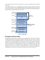
Once initialization software starts to run, the initialization code relocates the vector table to 0x00000000 by
copying the vector table from FLASH to DRAM.
The Initial Internal Space Base (ISB) bits in HRCW are also important because they determine the value of
the Internal Memory Map Register (IMMR). The IMMR value gives the starting address of the internal
memory map registers space. This example chose an ISB value of 10 which establishes the IMMR physical
base address at 0xFF000000.
Full descriptions of all bits in the HRCW are explained in the Reset section of the MPC860 PowerQUICC
User’s Manual. The MSR is accessed with the mtmsr and mfmsr assembly mnemonics. The MSR is
explained in the PowerPC Register Set chapter of the PowerPC™ Microprocessor Family: The
Programming Environments for 32-Bit Microprocessors Manual.
Register Initialization
Table 1 contains the list of most registers that were initialized and their values:
Table 1. Initialized Registers
Register
4
Description
Value
MSR
Machine State Register
0x1002
SRR1
Status Save/Restore Register
0x1002
HRCW
Hard Reset Configuration Word
0x4160
LR
Link Register
Current IP value
IMMR
Internal Memory Map Register
0xFF000000
SYPCR
System Protection Control Register
0xFFFFFF88
MPTPR
Memory Periodic Timer Prescaler Register
0x0800
MAMR
Machine A Mode Register
0xBBA21114
Example Software for the MPC860 Demonstrating Initialization
MOTOROLA