1
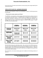
29 MAY 98
Freescale Semiconductor
Freescale Semiconductor, Inc...
Application Note
GETTING STARTED WITH THE MPC860:
A Design Guide
Netcomm Applications
Freescale, Austin, Texas
INTRODUCTION
Hello, and welcome to designing with Freescale’s MPC860 PowerQUICC!
We would like to thank you for choosing a Freescale processor. Freescale understands that in
the field of integrated communications controllers, you have a choice. We’re proud to have
your business.
We’d like to introduce you to some resources available to you as an 860 designer. Then
we’ll offer a step-by-step guide to developing hardware and software for the 860, and point
out materials that may support your efforts.
THE WEB
The World Wide Web has fast become the most efficient way to provide a wide variety of
support materials to customers. We invite you to visit our home on the web at:
http://www.mot.com/netcomm
The main NetComm home page tends to highlight new additions to the page and also
contains the links to the other sections of the site. As a designer, it is more likely that you will
© Freescale Semiconductor, Inc., 2004. All rights reserved.
For More Information On This Product,
Go to: www.freescale.com
Freescale Semiconductor, Inc.
find three other areas of our page most valuable: The Engineer’s Toolbox, the Publications
Library, and the Support & FAQ area.
The Engineer’s Toolbox
Click on the TOOLBOX for example code, schematics, monitor packages, part models,
initialization tools, and more. Files tend to be provided in a ZIP-compressed format or PDF
format for Adobe’s Acrobat Reader.
Freescale Semiconductor, Inc...
Publications Library
Click on PUBLICATIONS LIBRARY for our collection of
users manuals, technical
summaries, application notes (or “appnotes”), and user manual errata (listed as manual
addendums). Also in this section you will find user’s manuals for our software, downloadable
microcode packages, and our development systems.
Support & FAQ
Click on SUPPORT & FAQ to find the latest device errata, as well as find information on how
to subscribe to our Mailing Lists which periodically broadcasts device news.
The Frequently Asked Questions (FAQ) page provides a search engine that gives you the
power to parse through actual helpline database issues on our products, accumulated over
our years of experience. Why lose valuable time-to-market investigating a bug in your
design if someone has already asked us about the same issue? When in doubt, check it out
using the FAQ. Bookmark the link http://www.mot.com/netcommfaq to go directly to the FAQ
search engine.
THE MPC860 PowerQUICC USER’S MANUAL
The MPC860 User’s Manual provides the most detailed information about the part and its
operation. From I/O capabilities to programming models to interfaces, this is a must-have for
anyone working with the 860.
The manual’s document number is MPC860UM/AD and the manual can be obtained in
electronic format from the Publications Area of the web page or through the Literature
Distribution Center (discussed shortly).
We are also pleased to announce the pending release of the new REV 1 edition of the 860
User’s Manual. This new edition has updated tables and diagrams, improved organization of
the material, and new sections that better illustrate operation of the part to the reader. An
Acrobat PDF version of the REV 1 manual is availble in the Publications Library of our
website.
2
For More Information On This Product,
Go to: www.freescale.com
Freescale Semiconductor, Inc.
PowerPC 32-Bit MICROPROCESSOR MANUAL
This manual complements the MPC860 PowerQUICC User’s Manual by going into great
detail on such topics as the PowerPC register set, exceptions, and the PowerPC instruction
set. The document number is MPCFPE32B/AD.
Freescale Semiconductor, Inc...
THE MPC860 TRAINING CDROMS
NetComm is producing another valuable tool that will assist to educate yourself on the
operation of the MPC860. Derived directly from the 4-day training course available from
Freescale, NetComm is making available a set of MPC860 Training CDROMs. Certainly you
can use them to train yourself before you begin your design, but these discs should also prove
to be a handy reference once your design is underway. This training set introduces a wealth
of information to the new designer as well as serve as a collection of insights to reinforce the
knowledge of the experienced engineer. There are many ways in which you might want to use
this training. The information has been arranged in a sequential fashion, so if you desire, you
may proceed through the course from start to finish as though you were actually taking the
class. It is also possible to use the Table of Contents or the Keyword Index to randomly
access the material as if you were thumbing through a manual.
This CDROM set will be available through Freescale’s Literature Distribution Center, beginning
in June 1998 (estimated).
THE NETCOMM GENERAL INFORMATION CD-ROM
Tired of downloading large documents from our web-site? We offer user’s manuals and
large software packages such as the MCUinit processor initialization tool in a CD-ROM
format. While everything that is contained on this CD-ROM is also located on the web, this
disc may be more convenient for those customers with low-bandwidth access to the internet.
This disc may be obtained by contacting Freescale’s Literature Distribution Center using the
methods described in a moment, and requesting item CDRONETCOM/D. Use the web for
downloading smaller documents, and documents which could change frequently.
THE LITERATURE DISTRIBUTION CENTER
Hard copies of our manuals and CD-ROMs can be obtained by contacting Freescale
Semiconductor Product Sector’s Literature Distribution Center (LDC). The LDC’s web page
can currently be accessed through the Literature Retrieval area of:
http://www.mot-sps.com/sps/General/sales.html
Additional contact information is as follows:
USA/Europe/Locations Not Listed
3
For More Information On This Product,
Go to: www.freescale.com
Freescale Semiconductor, Inc.
P.O. Box 5405, Denver, Colorado 80217
1-800-441-2447 or 1-303-675-2140
Japan
Nippon Freescale Ltd.: SPD Strategic Planning Office
4-32-1, Nishi-Gotanda, Shinagawa-ku, Tokyo 141, Japan
81-3-5487-8488
Freescale Semiconductor, Inc...
Asia/Pacific
Freescale Semiconductors H.K. Ltd.
8B Tai Ping Industrial park
51 Ting Kok Road, Tai Po, N. T., Hong Kong
852-26629298
STEP-BY-STEP GUIDE TO DESIGNING WITH THE MPC860
IS THE 860 RIGHT FOR YOUR APPLICATION?
With the complexity of chips these days, it can take a lot of time to make sure that a given
chip is right for your board. Here are some steps you can take to make sure the MPC860 is
right for you.
1. Look at the MPC860 variations.
Go to http://www.mot.com/netcomm and click on the PRODUCTS icon. On the PRODUCTS
page you will see a list of MPC860 variations. Click on one of the variations and you will see
a table that illustrates the differences between the versions.
2. Obtain the right user’s manuals.
All the MPC860 family members require the MPC860UM/AD which is available from the web,
from our CD ROM called CDRONETCOM/D, and from the Literature Distribution Center. If
you want information on the MPC860MH, MPC860DH you will also need the QMC User’s
Manual supplement. If you need the MPC860SAR, you will want its supplement. If you want
the MPC860T, you will want its supplement that shows the differences between the base
MPC860 and that particular device.
If you are looking at one of the MPC850 family members, you would start with the base
MPC850 manual instead of the MPC860 manual.
3. Read the introduction section of the user’s manuals.
This will give you an overview of the features of the chips. If you are looking at the
MPC860DC (dual channel device) or MPC860DE (dual Ethernet) devices, then the MPC860
4
For More Information On This Product,
Go to: www.freescale.com
Freescale Semiconductor, Inc.
base manual still applies, but only SCC1 and SCC2 are available. SCC3 and SCC4 pins can
still be used as parallel I/O ports, but the SCC3 and SCC4 are non-functional.
4. Choose the Right Part for your Communications Functions
The next area to investigate is whether the communications functions on the MPC860 are
right for your application. Decide what serial functions you want to accomplish at the same
time. For example you may want Ethernet, HDLC and UART.
Freescale Semiconductor, Inc...
You could assign
SCC1 = Ethernet
SCC2 = HDLC
SCC3 = UART
Since Ethernet is one of the choices, this rules out the “MPC860”, leaving the MPC860DC,
MPC860DE, MPC860DH, MPC860EN and MPC860MH.
If the HDLC support is multi-channel such as 24/32 time slots on fractional T1/E1 or several
ISDN BRI’s, this narrows the choice to the MPC860DH or MPC860MH. This protocol is
called Quicc Multi-Channel Controller (QMC) in our documentation.
Now the choices become:
MPC860MH
SCC1 = Ethernet
SCC2 = Multi-channel HDLC (also called QMC)
SCC3 = UART
But wait, the MPC860DH only has 2 SCCs! Can it be used? Yes, because it has 2 SMCs
also, which are capable of low speed UARTs! So the MPC860DH is also possible:
MPC860DH
SCC1 = Ethernet
SCC2 = Multi-channel HDLC
SMC1 or SMC2 = UART
Finally, it should be noted that the functions on SCC1 and SCC2 can be switched if needed
on parts that offer Ethernet on more than one channel such as the MPC860MH and
MPC860DH.
What about the MPC850? Can it be used. The MPC850DH offers less CPU performance
and less capable communications functions, but the necessary functions can still be mapped
as follows:
MPC850DH
SCC2 = Ethernet
SCC3 = Multi-channel HDLC
5
For More Information On This Product,
Go to: www.freescale.com
Freescale Semiconductor, Inc.
SMC1 = UART
From reading section 1 of the MPC850DH manual, you will see that even though this part
has 2 SCCs, they are actually “SCC2 and SCC3” since SCC1 is replaced with a dedicated
USB controller. In addition the MPC850DH only has one SMC that can be connected to its
own set of pins, so only SMC1 is possible.
Conclusion: So far, our most realistic options for this application are the MPC860DH and the
MPC850DH. Can both be used? It probably depends on the CPU performance required,
which is discussed later. For now, let’s stick with the MPC860DH for our example.
Freescale Semiconductor, Inc...
5. Check the Pinout of the Desired Part
In our example, we need to make sure that the MPC860DH will all the pins operating
simultaneously to support:
MPC860DH
SCC1 = Ethernet
SCC2 = Multi-channel HDLC
SMC1 or SMC2 = UART
A reading of the Ethernet section of the manual shows us that the following pins are required
if Ethernet is used on SCC1:
TXD1
TENA which is mapped onto RTS1
TCLK which must be mapped to CLK1, CLK2, CLK3 or CLK4
RXD1
RENA which is mapped onto CD1
RCLK which must be mapped to CLK1, CLK2, CLK3 or CLK4, but must be a different pin
than the one used for TCLK above
CLSN which is mapped onto CTS1
Now go to the Signals Description of the Manual and look for those signals and circle them.
Now for the Multi-Channel HDLC support. This requires a time-slot assigner A or time-slot
assigner B. Which one should we use? You can use either -- whichever makes the rest of
the pin assignment easier. For this example, lets assume that the receive and transmit sides
are completely independent and therefore require their own separate clocks and
synchronization pins. Then the pins we need are:
Choice 1 is TDM A
L1TXDA
L1RXDA
L1TCLKA
L1RCLKA
L1TSYNCA
6
For More Information On This Product,
Go to: www.freescale.com
Freescale Semiconductor, Inc.
L1RSYNCA
Choice 2 is TDM B
L1TXDB
L1RXDB
L1TCLKB
L1RCLKB
L1TSYNCB
L1RSYNCB
Freescale Semiconductor, Inc...
Note that these pins are easily distinguished from other SCC functions because they all start
with L1 (Layer 1). If only one clock and one sync was needed then only L1RCLKx and
L1RSYNCx would be used.
Now go to the Signals Description of the manual and look for these signals and circle them.
For our example, we will choose TDM A rather than TDM B.
What you will notice is that L1RCLKA is an alternate function of CLK1 and L1TCLKA is an
alternate function on CLK3. Thus, we should go back to our Ethernet selections above, and
choose CLK2 and CLK4 so there is no conflict.
Another interesting thing to note is that L1TSYNCA and L1RSYNCA are available in 2 places
on the device! You can pick either location, and select it later in your software initialization.
Why did we do this? In a few case studies we did, we found that certain key applications
required this kind of flexibility, otherwise we would not have added this extra complication to
the device!
Lastly, we need to select an SMC to use for the UART. Either SMC1 or SMC2. Thus our
choices are:
SMTXD1
SMRXD1
or
SMTXD2
SMRXD2
Note that the use of the SMCs means that we do not have RTS, CTS and CD functions. (If
you must have those functions, and software interrupts are not sufficient, then an SCC must
be used, putting the application back to an MPC860MH rather than the MPC860DH.)
An examination of the pinout reveals that indeed, everything fits on the MPC860DH, and it
really didn’t matter which SMC we chose, and which TDM we chose in this case. As you
start to use more channels, and more of the “optional” signals on certain interfaces, the
chances of a contention increases.
6. Check the Dual-port RAM of the Desired Part
7
For More Information On This Product,
Go to: www.freescale.com
Freescale Semiconductor, Inc.
So now we know that the MPC860DH supports the simultaneous use of all the pins we need.
SCC1 = Ethernet
SCC2 = Multi-HDLC (also called QMC) on TDM A
SMC1 = UART
Freescale Semiconductor, Inc...
What is the next resource that could be a problem? The answer is the Dual-port RAM. Each
protocol requires certain parameters that are stored in the dual-port RAM. In the case of
certain complicated protocols like Ethernet and Multi-HDLC the parameter RAM requirement
is so large that it actually overruns the parameter RAM of other protocols. In our example
Ethernet on SCC1 overruns the I2C area, and QMC on SCC2 overruns the SPI area.
To solve this we have several downloadable microcodes that “patch” this problem by moving
I2C and SPI parameter RAM to other locations. This is called the “Microcode Patch for
Relocating 12C/SPI Parameters” and is available from the ENGINEERS TOOLBOX on our
web-site.
7. Check the CPM Performance
Now that the pins and dual-port RAM requirements are checked to be OK for our application,
we need to check that the Communications Processor Module (CPM) performance is
sufficient for the application.
The method used to determine this is illustrated in the User’s Manual Appendix A, and
involves a simple equation based upon the system clock speed of the 860, as well as the
protocols required and their speeds. This Appendix lists the maximum expected performance
of the 860 at 25 MHz for each kind of functionality the 860 provides. This chart scales
linearly, so as an example, if you intend to run the 860 at 50MHz, then these maximum
bandwidth numbers also double.
We also offer an Excel spreadsheet called “CPM Performance Spreadsheet” that performs
these CPM loading calculations for you and it is located in the Engineer’s Toolbox of our web
page. This is a very useful tool!
To perform these calculations by hand, simply divide the intended bandwidth of a certain
protocol by the maximum, repeat for any additional functions you will be using, add all these
fractions together, and do not exceed a sum of 1.
Let’s do a quick example to illustrate what we are describing. If the 860 were operating at
25MHz, and would be using a 10Mbit Ethernet channel in half duplex, a 2Mbit HDLC
channel, a 64 Kbit HDLC channel, a 9.6 Kbit UART and a 38Kbit SMC UART, you would take
these bandwidths, divide them by the max for each protocol, and sum them as follows:
10/22 + 2/8 + 0.064/8 + .0096/2.4 + 0.038/0.22 = 0.96
which comes close to, but does not exceed 1. So the processor would not be overloaded.
8
For More Information On This Product,
Go to: www.freescale.com
Freescale Semiconductor, Inc.
If you were to attempt 32 QMC channels at 64 Kbit each and one additional 2Mbit channel
with the 860 at 25MHz, the following equation applies:
(32 * 0.064)/2.1 + 2/8 =1.22
This arrangement will not work. You can, however, keep this arrangement if you increase
the operating speed of he 860 to 33MHz.
1.22 * 25/33 = 0.92
Freescale Semiconductor, Inc...
Now the CPM is not overloaded.
8. Check the PowerPC CPU Performance
The last main area of concern is the CPU Core Performance. Our CPU offers the following
Dhrystone MIPS performance:
At 66 Mhz, the 860 performed 87 Dhrystone MIPS
At 50 MHz, the 860 performed 66 Dhrystone MIPS
At 40 MHz, the 860 performed 52.8 Dhrystone MIPS
At 33 MHz, the 860 performed 43.56 Dhrystone MIPS
At 25 MHz, the 860 performed 33 Dhrystone MIPS
These numbers were obtained with a Diab Compiler.
The good news about the Dhrystone benchmark is that the results for it, are available from a
wide variety of processors. The bad news about the Dhrystone benchmark is that it fits
completely in internal cache of 2K instructions or greater. Thus, the Dhrystone benchmark
shows the 4K/4K (instruction cache/data cache size) MPC860 family to be the same speed
as the 2K/1K MPC850 family.
In actuality the performance of the MPC860 is 10-35% greater than the MPC850 family at the
same clock speed.
Another metric commonly used for the MPC860 is that this processor is about 10% faster
than the 68040 processor at the same clock speed (which also has 4K/4K cache).
Finally, our TOOLBOX offers a benchmark “shell” which allows you to benchmark your own
code on our processor. This shell of code initializes the chip, turns on the MMU and Caches,
and starts a timer for you. It also shows you where to place your own “test code” to see how
long it takes to run. The example code that is included in this shell is the Dhrystone code.
9. Price and Availability
This information is not available on our web site, so check with your local distributor or
Freescale representative. Freescale’s main distributors are Arrow, Future, Hamilton-Hallmark
and Wyle. Our web site does contain press releases which show the “direct from Freescale”
9
For More Information On This Product,
Go to: www.freescale.com
Freescale Semiconductor, Inc.
pricing at the time of the device announcement, however pricing does change drastically with
volume and with time.
STEP-BY-STEP GUIDE FOR HARDWARE DESIGNERS
Now that you have decided to actually use the MPC860 in a design, the following steps are
recommended.
Freescale Semiconductor, Inc...
1. Determine the memory system you will need.
The MPC860 is a bursting device and thus obtains the best performance when the memory it
is connected to is also able to burst. The MPC860 burst is comprised of four 32-bit words. If
the length of the burst is written as 4-2-2-2, then the first 32-bits were read/written in 4
clocks, the next 32-bits in 2 clocks, and so on for a total burst length of 10 clocks. The
following table shows some example burst lengths for a BURST READ operation. (BURST
WRITES are usually slightly better).
Note that faster memory can yield better results. Also note that for the 66 Mhz devices (or
any device used in half speed bus mode) the actually bus speed may only be one half of the
processor speed. Thus a 66 Mhz device might only have a 33 Mhz external bus. Whether a
66/33 (internal/external) device is faster than a 50/50 device will depend on the cache hit rate
and the external memory speed.
More information on the various memory types can be obtained in the following collection of
appnotes:
10
For More Information On This Product,
Go to: www.freescale.com
Freescale Semiconductor, Inc.
MPC860 Interface to Fast Page Mode DRAM
MPC860 Interface to EDO DRAM
MPC860 Interface to Synchronous DRAM (SDRAM)
2. Obtain Example Schematics
Freescale Semiconductor, Inc...
The web site offers several sources of example schematics available in ORCAD format. The
most useful set is probably the SAMBA schematics, which shows how to interface the entire
MPC860 family to memory -- Flash EPROM, DRAM, and SDRAM. In addition, it shows the
MPC860T connected to an external 10/100baseT Transceiver.
In addition, the schematics for our MPC860FADS boards are also available, however, this
board is designed to be very flexible, and may not represent the most efficient system
design.
860 PART SYMBOL: An 860 electronic part symbol in ORCAD Capture format is also on the
web.
BGA FOOTPRINT: The documents AN1231 and AN1232 are in-depth discussions about
factors regarding the BGA package that the 860 uses and includes a footprint for design
purposes.
3. Obtain User’s Manual Errata and Device Errata
This information is available on our web site in the PUBLICATIONS and SUPPORT & FAQ
sections respectively.
4. Remember the 5V Tolerance
Although the MPC860 family is a 3.3V supply device, it is 5V tolerant and can be used with
5V TTL compatible components.
5. Look at Clocking Issues
Although the part allows both crystals and oscillators to be used, we recommend oscillators
to be used if possible. Oscillators reduce the risk of process variations or process shrinks
from causing the clocking circuit to cease operation.
For those that must use crystals, we recommend that engineers inquire to their crystal
manufacturer to determine the best capacitor and crystal characteristics. They are in the best
position to estimate the values needed for the circuit.
We do provide the appnote “Crystal Note for the 302, 360 and 8XX Family.” This paper is
written to assist engineers in the production of reliable clock circuits which may be used with
11
For More Information On This Product,
Go to: www.freescale.com
Freescale Semiconductor, Inc.
devices such as the MPC860, MC68360 and MC68302 and their derivatives. It discusses in
general terms various methods for the generation of the system clock.
6. Look at Pin Termination
A frequent issue of concern is the proper termination of signal pins. This is the most
common reason why a MPC860 board does not work at power-up. Which pins should be
pulled up or down for proper operation of the 860? Please see the External Signals section
of the new MPC860 manual, found in the Publications Area of the web.
Freescale Semiconductor, Inc...
7. Look at Pin Timing Issues
When designing your circuits involving the 860 you will obviously take care to meet the timing
specifications of the 860. In addition to the timing diagrams in the 860 manual, we also
provide some additional tools to help understand your timing needs.
On the web, in the Publications Area, is the MPC860 Electrical Specifications Spreadsheet.
This Excel document dynamically calculates timing specifications based upon operation
speed and capacitive loading. You can program the exact frequency of your system bus,
and this tool will customize the MPC860 timings for you. In addition, you can program the
capacitive loading on the pins, and the tool will customize the timings.
We also have available an electronic data book of the 860 timings that can be used with
Chronology’s TimingDesigner tool. This software aids in visualizing signal waveforms and
timings. For details, contact Kevin Silver at Chronology at 1-800-800-6494 ext.113.
8. Check the Hardware Configuration Register Carefully
The MPC860 has a number of different modes that can be programmed in hardware. You
select the modes by driving certain voltage levels onto the Data Bus pins during reset. Any
Data Bus pins that you do not drive will take on the default configuration. Out of the 15 or so
pins, you will probably only need to drive 4 or 5 -- the rest can use the defaults. Please read
this section of the manual very carefully as you are making very basic decisions about the
operation of the part.
9. Read the Design Checklist
When you think you have everything under control, go back and read the MPC860 Design
Checklist which resides in the PUBLICATIONS section of our web site. This gives a number
of helpful hints and lists some common mistakes.
10. Get the part up and running.
12
For More Information On This Product,
Go to: www.freescale.com
Freescale Semiconductor, Inc.
When you get the boards back, the first thing you should do is bring the part up in its debug
mode. In the debug mode, you can control the part through the debug port without requiring
the device to execute any software on the board itself. The debug port pins of the MPC860
should be brought to a simple header that is described in the APPLICATIONS section of the
MPC860 User’s Manual. This will allow many standard debuggers to access the device. In
fact, if you purchased an MPC860 FADS board, you can use our MPC8bug on the host PC
to control to your target board through the MPC860 FADS board. See the MPC860FADS
manual for more information on this option.
11. Having Trouble?
Freescale Semiconductor, Inc...
Don’t forget to check the searchable FAQ at:
http://www.mot.com/netcommfaq
for hints on what might be wrong.
12. Get on the MPC860-Update List Server
See the SUPPORT & FAQ section of our web site to subscribe to get real-time updates of
late breaking news on the MPC860.
STEP-BY-STEP GUIDE FOR MECHANICAL AND COMPONENT ENGINEERS
Here are some additional steps to consider.
1. Read the Packaging Appnote
The MPC860 family resides in a 357 lead Plastic Ball Grid Array (PBGA) package. An
appnote for the use of this package and PBGAs in general may be found at:
http://www.mot.com/pbga
2. Look at Thermal Considerations
NetComm is soon making available in the Publications Area a new appnote covering thermal
considerations and measurements for the 860 and its packages.
If extended temperature (-40 to +85) is required, may not be offered in at all speed grades,
and may require heat sinks at the highest speed grades.
3. Look at Power Dissipation
13
For More Information On This Product,
Go to: www.freescale.com
Freescale Semiconductor, Inc.
The MPC860 family tends to vary from 0.4W to 0.8W depending on frequency. The power
dissipation at a given frequency is decreasing as the device undergoes shrinks. Meanwhile
the offered frequency is increasing over time. The end result is that the power dissipation for
the highest speed versions tend to be in the 0.8W range.
The first MPC860 User’s Manual showed an option of running the internal circuitry of the
MPC860 family at 2.2V (rather than 3.3V) to save power. This option has NOT been
productized in the MPC860 or MPC850 family, and is not available.
Freescale Semiconductor, Inc...
4. Qualification Data
Qualification reports are available for our devices, however they can only be obtained
through a Freescale Sales office.
STEP-BY-STEP GUIDE FOR SOFTWARE DESIGNERS
1. Determine Your Tool Set
An incredible amount of support is also available in many forms from companies outside of
Freescale. A list of those companies organized by category of support, their contact
information and links to their web sites (if available) are located on our web site. At the top of
various pages throughout our web site you will see links to the 860 Third Party Support
Page.
Categories of support include: Board Test Consultants, Chip Drivers (Software), Generators
and Tools, Companion or Support Chips, Development Systems, Emulators, Hardware
Models, Network Software, Operating Systems, and Package & Socket Adapters.
We highly encourage you to investigate these companies products and services in your
efforts to get your product to market.
2. Review the Freescale Application Development System Materials
Among the most important support materials available to our customers is the MPC8xx
Family Application Development System (8xxFADS). This package is meant to serve as a
platform for software and hardware development around the 860 family of devices. Using
the on board resource and the associated MPC8bug debugger/monitor, a developer is able
to load their code, run it, set breakpoints, display memory and registers and connect the
developer’s own proprietary hardware via the expansion connectors. The FADS is not just
effective for testing purposes but can also serve as a demonstration tool. Contact your local
Freescale Sales office for details on how to purchase the systems. Information on how to find
the most appropriate sales channel can be found on the web.
MPC8BUG
14
For More Information On This Product,
Go to: www.freescale.com
Freescale Semiconductor, Inc.
Freescale provides its own command line debugger/monitor program called MPC8bug. This
package provides excellent simple methods of observing and debugging your code and
performing diagnostics. You can even write your own diagnostics with the new 1.3 release of
the software. This software is shipped with the 860ADS or 8xxFADS, and is also available
on the web.
3. Acquire MCUinit
Freescale Semiconductor, Inc...
Interested in using a graphic interface tool to quickly produce initialization code for the 860?
You need to check out MCUinit, a menu-driven initialization code generating program for 32bit Windows compatible computers. This software package is located both on the web and
on the NetComm General CDROM.
4. Study Exception Processing and Interrupts
There is also the MPC860 EPPC Exception Processing Application Note with deals with
exception processing in more detail.
In addition, two appnotes are provided on interrupts -- one for the SIU and one for the CPM.
5. Obtain Basic Chip Initialization Code
Look in the ENGINEERS TOOLBOX on the web to obtain the latest MPC860 Initialization
code. This shows how to bring the device up from power-up including the programming of
clocking modes and chip selects.
6. Obtain Device Drivers and Example Code
The Engineers’ Toolbox is your best resource for freeware available from Freescale for use
with the 860. On the web you will find both simple tutorial-style examples, and some
complex drivers as well, that demonstrate a wide variety of protocols and modes of operation
from setting up timers to running Ethernet. The list of code available is being updated all the
time, so check the web often. We currently have drivers or example code for HDLC,
Ethernet, UART, Transparent, Real-time clock, I2C, the PowerPC Timebase, ATM SAR for
the MPC860SAR.
Drivers are also available for a fee from third parties such as AISYS, Inverness, and Trillium
and are often included with a purchase of an RTOS for the MPC860.
7. Read the CPU Performance Appnote
The MPC860 core has two Memory Management Units and two caches, one of each for data
and for instructions. We invite you to study our Cache and MMU appnote package, available
in the Publications area of the NetComm web site, which explains how to efficiently use the
15
For More Information On This Product,
Go to: www.freescale.com
Freescale Semiconductor, Inc.
caches and MMU. It includes the appnote itself, a special version of the debugger/monitor
NetComm offers with cache hit simulation ability, and some scripts (given as examples in the
appnote) that can be used with the debugger. The appnote is named “MPC8XX
Performance Driven Optimization of Caches and MMUs”.
8. Scan the Performance Checklist
Freescale Semiconductor, Inc...
In the Publications Library is the MPC860 CPU Performance checklist. This document is
basically a quick summary of the most important facets of the Performance Appnote
mentioned above. Topics that are covered include dealing with DRAM, interrupts and their
handlers, core operation modes and more. If you are not getting the performance you
expect, this is the place to start.
The MPC860 has so many debug assist modes that it is not uncommon for customers to see
a 2x to 3x performance improvement, after following the guidelines in this checklist.
9. Having Trouble?
If you are having trouble getting your serial protocols to work try looking at the appnote “Hints
for Debugging the CPM”. This shows you how to determine where the problem resides, by
showing you how to trace the flow of data from system memory to the pins, and from the pins
to system memory.
Also, don’t forget to check the searchable FAQ at:
http://www.mot.com/netcommfaq
10. Get on the MPC860-Update List Server
See the SUPPORT & FAQ section of our web site to subscribe to get real-time updates of
late breaking news on the MPC860.
16
For More Information On This Product,
Go to: www.freescale.com
Freescale Semiconductor, Inc.
How to Reach Us:
Home Page:
www.freescale.com
Freescale Semiconductor, Inc...
E-mail:
[email protected]
USA/Europe or Locations Not Listed:
Freescale Semiconductor
Technical Information Center, CH370
1300 N. Alma School Road
Chandler, Arizona 85224
+1-800-521-6274 or +1-480-768-2130
[email protected]
Europe, Middle East, and Africa:
Freescale Halbleiter Deutschland GmbH
Technical Information Center
Schatzbogen 7
81829 Muenchen, Germany
+44 1296 380 456 (English)
+46 8 52200080 (English)
+49 89 92103 559 (German)
+33 1 69 35 48 48 (French)
[email protected]
Japan:
Freescale Semiconductor Japan Ltd.
Headquarters
ARCO Tower 15F
1-8-1, Shimo-Meguro, Meguro-ku,
Tokyo 153-0064
Japan
0120 191014 or +81 3 5437 9125
[email protected]
Asia/Pacific:
Freescale Semiconductor Hong Kong Ltd.
Technical Information Center
2 Dai King Street
Tai Po Industrial Estate
Tai Po, N.T., Hong Kong
+800 2666 8080
[email protected]
For Literature Requests Only:
Freescale Semiconductor Literature Distribution Center
P.O. Box 5405
Denver, Colorado 80217
1-800-441-2447 or 303-675-2140
Fax: 303-675-2150
[email protected]
17
Information in this document is provided solely to enable system and software
implementers to use Freescale Semiconductor products. There are no express or
implied copyright licenses granted hereunder to design or fabricate any integrated
circuits or integrated circuits based on the information in this document.
Freescale Semiconductor reserves the right to make changes without further notice to
any products herein. Freescale Semiconductor makes no warranty, representation or
guarantee regarding the suitability of its products for any particular purpose, nor does
Freescale Semiconductor assume any liability arising out of the application or use of
any product or circuit, and specifically disclaims any and all liability, including without
limitation consequential or incidental damages. “Typical” parameters which may be
provided in Freescale Semiconductor data sheets and/or specifications can and do
vary in different applications and actual performance may vary over time. All operating
parameters, including “Typicals” must be validated for each customer application by
customer’s technical experts. Freescale Semiconductor does not convey any license
under its patent rights nor the rights of others. Freescale Semiconductor products are
not designed, intended, or authorized for use as components in systems intended for
surgical implant into the body, or other applications intended to support or sustain life,
or for any other application in which the failure of the Freescale Semiconductor product
could create a situation where personal injury or death may occur. Should Buyer
purchase or use Freescale Semiconductor products for any such unintended or
unauthorized application, Buyer shall indemnify and hold Freescale Semiconductor
and its officers, employees, subsidiaries, affiliates, and distributors harmless against all
claims, costs, damages, and expenses, and reasonable attorney fees arising out of,
directly or indirectly, any claim of personal injury or death associated with such
unintended or unauthorized use, even if such claim alleges that Freescale
Semiconductor was negligent regarding the design or manufacture of the part.
For More Information On This Product,
Go to: www.freescale.com