1
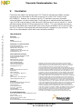
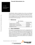
Order this document by
AN2131
Freescale Semiconductor
Freescale Semiconductor, Inc...
12/99
REV 1
Application Note
MPC8260ADS - REVISING CODE DESIGNED FOR
THE ENG BOARD TO ALSO RUN ON THE PILOT
BOARD
Netcomm Applications
Freescale, Austin, Texas
I.
Purpose –
Differences between the ENG and PILOT revisions of the MPC8260ADS board (ADS) may
impact preliminary application development and Third Party Developers’BSP’s. This
application note is provided as a quick template to revise code which was developed using the
ENG revision but now needs to be ported to the PILOT revision of the MPC8260ADS. This
note will not discuss additional features of the PILOT board, as these would not affect code
which was written for the ENG board revision. For complete information on the MPC8260ADS,
refer to the MPC8260ADS User’s Manual, Rev 0.213, dated November, 1999 (ADS UM) at:
http://www.mot.com/netcomm.
The ENG board was the first release of the board, the last of these were shipped in
November, 1999. The PILOT board is the second release of the board, which began shipping
at the end of November 1999. Both boards have a sticker which clearly indicates if they are
ENG or PILOT. The ENG revision’s sticker is located between DS1 and LD16. The PILOT
revision’s sticker is located just above the ATM port, U1.
II.
The Board Control and Status Registers (BCSRx) © Freescale Semiconductor, Inc., 2004. All rights reserved.
The bit values of BCSR0 and BCSR1 are now located at D(0:7) on the PILOT revision. On the
ENG revision, the bit values were located at D(24:31).
© Freescale Semiconductor, Inc., 2004. All rights reserved.
© Motorola Inc., 1998. All rights reserved.
For More Information On This Product,
Go to: www.freescale.com
Freescale Semiconductor, Inc.
BCSR0 Refer to the ADS UM, Table 4-9. The bits implemented on the ENG revision which have
changed bit positions on the PILOT board are:
Freescale Semiconductor, Inc...
BIT
SIGNAL_LAMP_0
SIGNAL_LAMP_1
ENG
30
31
PILOT
6
7
BCSR0[30,31] on the PILOT board are designated as Reserved, un-implemented. In fact,
these bits are not going to become implemented, so it is safe to leave these bits toggled in
PILOT board code revisions in order to allow code to be compatible for both the ENG and
PILOT revisions of the ADS. However, BCSR2 now contains a Board Revision Number, which
can be used to choose which BCSR0 bits to implement. See ADS UM, Table 4-11.
Quickfind: Typical Location in Code These bits control the General Purpose LED0 at LD11 and the General Purpose LED1 at
LD12. These LED’s are typically used to give a visual indication that a part of code is
executing normally. Some applications illuminate these to indicate that packets were sent and
received successfully.
BCSR1 Refer to the ADS UM, Table 4-10. The bits implemented on the ENG revision which have
changed bit positions on the PILOT board are:
BIT
ATM_EN
ATM_RST
FETHIEN
FETH_RST
RS232EN_1
RS232EN_2
ENG
26
27
28
29
30
31
PILOT
2
3
4
5
6
7
BCSR1[26-31] on the PILOT board are designated as Reserved, un-implemented. In fact,
these bits are not going to become implemented, so it is safe to leave these bits toggled in
PILOT board code revisions in order to allow code to be compatible for both the ENG and
PILOT revisions of the ADS. However, BCSR2 now contains a Board Revision Number, which
can be used to choose which BCSR1 bits to implement. See ADS UM, Table 4-11.
Quickfind: Typical Location in Code ATM - The ATM_RST is used to reset the ATM phy device. The ATM_EN is used to enable
the ATM phy device. These bits will typically be implemented in code which actually passes
packets over the ATM phy or which demonstrate the ATM in external loopback mode. They do
not affect code which only runs ATM on the MPC8260 in internal loopback mode.
Fast Ethernet - The FETH_RST is used to reset the Fast Ethernet phy device. The FETHIEN
is used to enable the Fast Ethernet phy device. These bits will typically be implemented in
2
For More Information On This Product,
Go to: www.freescale.com
Freescale Semiconductor, Inc.
code which actually passes packets over the Fast Ethernet phy or which demonstrate Fast
Ethernet in external loopback mode. They do not affect code which only runs Fast Ethernet on
the MPC8260 in internal loopback mode.
Serial Port 1 - The RS232EN_1 enables the DB9 connector at PB3. This bit is implemented in
code which transmits/receives on the RS232 -1 port, such as a dumb terminal. One obvious
application of this bit will be in FLASH monitor code.
Freescale Semiconductor, Inc...
Serial Port 2 - The RS232EN_2 enables the DB9 connector at PA3. This bit is implemented in
code which transmits/receives on the RS232 -2 port, such as a dumb terminal. A possible
application of this bit could be in FLASH monitor code.
III.
The Hard Reset Configuration Word (HRCW)
The PILOT revision of the ADS is currently shipping with the processor XPC8260, revision 0.2,
mask J24M. The board will be shipped with this processor until March 2000, (at which time,
the board will ship with the XPC8260, revision A.1, which will not be bound by the following
restriction). The only HRCW available on the PILOT board with the 0.2 processor is the
one supplied by the MACH PLD at U17, which is hard coded to contain the value 0C B2
02 05. Refer to the ADS UM, Table 4-1. (And you may wish to refer also to the MPC8260
User’s Manual ((MPC8260UM/D Rev. 0)) Table 5-7).
NOTE: The PILOT board is shipped with DS1-1 in the BSCR position (which is OFF), selecting
the HRCW from the MACH PLD. While using the 0.2 processor, do not change this switch
setting. (refer to ADS UM, section 2.3.4).
The software implications of this HRCW will be application-specific, predominantly affecting
code which boots up from FLASH. It is imperative that you study this HRCW value and modify
your code to accept these values throughout, or change the affected register values after bootup to the values your code requires, excepting some restrictions detailed below.
ENG vs PILOT board HRCW FLASH boot-up code written for and run on the ENG board does indeed use the HRCW
programmed at the first locations in the FLASH module, regardless of the revision of XPC8260
processor used. This is due to the addressing of the FLASH on the ENG board, A0-A2 of the
FLASH was implemented with Buffered Addresses (BA [29:27]), refer to the MPC8260ADS
schematics, rev ENG, sheet 5. On the PILOT board, the addressing of the FLASH module
was changed so that A0-A2 of the FLASH is now implemented with Burst Addresses (BADDR
[29:27]), refer to the MPC8260ADS schematics, rev PILOT, sheet 5.
However, one of the erratum of the XPC8260 rev 0.2, is that this processor does not
implement the Burst Addresses during Power-On or Hard Reset. Therefore, on the PILOT
board using the 0.2 processor, the FLASH will never be accessed during Power-On or Hard
Reset, so regardless of the HRCW programmed into this FLASH, it will not be accessed. Chip
Select 0 (CS0) during boot-up will only access the MACH PLD which will provide the HRCW
values 0C B2 02 05.
3
For More Information On This Product,
Go to: www.freescale.com
Freescale Semiconductor, Inc.
NOTE: While modifying code written for the ENG board to function on the PILOT board with
the 0.2 processor, keep in mind that once the 0.2 processor is replaced with the A.1 or later
revision of the processor, and DS1-1 is switched to the FLASH-booting option, the HRCW in
the FLASH will be invoked. Therefore, the HRCW residing at the beginning of your FLASH
code must be congruent with your code changes for future compatibility.
An Example : Init8260 -
Freescale Semiconductor, Inc...
Probably the best way to demonstrate the affect this hard coded HRCW may have on a
FLASH boot-up program is to detail what needed to be changed in our Init8260 FLASH bootup example, which will soon be available on our web page at http://www.mot.com/netcomm.
The most severe restriction of the hard coded HRCW to our Init8260 FLASH boot-up code
example was the Core Initial Prefix (CIP), bit 6. This bit sets the Machine State Register Initial Prefix (MSR[IP]) equal to 1, which places the system exception vector table at offset
0xFFF00000. There is no way to work around this offset, all code must accept and adjust to
this value. Our code had the exception table at offset 0x00000000, which required re-linking
the Init8260 boot-up example exception vector table to the offset 0xFFF00000. For some
compilers, this linking to offset 0xFFF00000 for the exception vector table is not clearly
documented and therefore not easily implemented.
L2 Cache Pins Configuration (L2CPC) =10. This value must not be changed by the software
as it configures the Burst Address Lines 29-31 (BADDR29 - BADDR31). BADDR27 BADDR29 are now used to address the FLASH, of which BADDR29 is provided by this L2CPC
configuration. The cache module of our Init8260 code had independently set these bits to their
cache implementation values, so this code module had to be changed to accept the value of
10. This value is necessary regardless of the revision of the processor. See the
MPC8260 User’s Manual (MPC8260UM/D Rev. 0) Table 4-12.
Data Parity Pins Configuration (DPPC), bits 10:11. These bits set the DPPC to the value of
11, which among other things, disables the Time Base. We use the Time Base in our Init8260
example code. Consequently, we had to modify our code to change the SIUMCR(DPPC) to
the value 10 after boot-up, in order to enable the Time Base (TBEN). See the MPC8260 User’s
Manual (MPC8260UM/D Rev. 0) Table 4-12.
IV.
The 60X SDRAM Mode Register change needed for
PILOT revision.
The final thing that we know to be aware of in modifying code written for the ENG board in
order to make it compatible with the PILOT board, is the 60X SDRAM Mode Register - Bank
Select Multiplex Address Lines (PSDMR.BSMA). The ENG revision accepted the value of
100, which selected address pins A16-A18, for bank-selecting the 60X SDRAM. The PILOT
board must have this value set to 011, selecting address pins A15-A17, for bank-selecting the
60X SDRAM. The value of 011 is also acceptable to use with the ENG revision of the ADS
board. This value is necessary regardless of the revision of the processor. See the
MPC8260 User’s Manual (MPC8260UM/D Rev. 0) Table 10-7.
4
For More Information On This Product,
Go to: www.freescale.com
Freescale Semiconductor, Inc.
V.
Conclusion
Freescale Semiconductor, Inc...
Every effort was made in the design of the PILOT board to minimize the software changes
necessary to run code written for the ENG revision to run on the PILOT revision of the
MPC8260ADS. However, the changes to the PILOT board were necessary to provide
enhanced features, such as bursting from FLASH and also to make this board recoverable in
case of HRCW erasure (when is used with an XPC8260 processor such as revision A.1, which
will allow booting with the HRCW programmed into FLASH). The code examples we have on
the web at http://www.mot.com/netcomm have nearly all been modified to run on both the ENG
and PILOT revisions of the board and are therefore specific examples for your reference. The
titles of the code examples reflect which ones have been modified.
How to Reach Us:
Home Page:
www.freescale.com
E-mail:
[email protected]
USA/Europe or Locations Not Listed:
Freescale Semiconductor
Technical Information Center, CH370
1300 N. Alma School Road
Chandler, Arizona 85224
+1-800-521-6274 or +1-480-768-2130
[email protected]
Europe, Middle East, and Africa:
Freescale Halbleiter Deutschland GmbH
Technical Information Center
Schatzbogen 7
81829 Muenchen, Germany
+44 1296 380 456 (English)
+46 8 52200080 (English)
+49 89 92103 559 (German)
+33 1 69 35 48 48 (French)
[email protected]
Japan:
Freescale Semiconductor Japan Ltd.
Headquarters
ARCO Tower 15F
1-8-1, Shimo-Meguro, Meguro-ku,
Tokyo 153-0064
Japan
0120 191014 or +81 3 5437 9125
[email protected]
Asia/Pacific:
Freescale Semiconductor Hong Kong Ltd.
Technical Information Center
2 Dai King Street
Tai Po Industrial Estate
Tai Po, N.T., Hong Kong
+800 2666 8080
[email protected]
Information in this document is provided solely to enable system and software
implementers to use Freescale Semiconductor products. There are no express or
implied copyright licenses granted hereunder to design or fabricate any integrated
circuits or integrated circuits based on the information in this document.
Freescale Semiconductor reserves the right to make changes without further notice to
any products herein. Freescale Semiconductor makes no warranty, representation or
guarantee regarding the suitability of its products for any particular purpose, nor does
Freescale Semiconductor assume any liability arising out of the application or use of
any product or circuit, and specifically disclaims any and all liability, including without
limitation consequential or incidental damages. “Typical” parameters which may be
provided in Freescale Semiconductor data sheets and/or specifications can and do
vary in different applications and actual performance may vary over time. All operating
parameters, including “Typicals” must be validated for each customer application by
customer’s technical experts. Freescale Semiconductor does not convey any license
under its patent rights nor the rights of others. Freescale Semiconductor products are
not designed, intended, or authorized for use as components in systems intended for
surgical implant into the body, or other applications intended to support or sustain life,
or for any other application in which the failure of the Freescale Semiconductor product
could create a situation where personal injury or death may occur. Should Buyer
purchase or use Freescale Semiconductor products for any such unintended or
unauthorized application, Buyer shall indemnify and hold Freescale Semiconductor
and its officers, employees, subsidiaries, affiliates, and distributors harmless against all
claims, costs, damages, and expenses, and reasonable attorney fees arising out of,
directly or indirectly, any claim of personal injury or death associated with such
unintended or unauthorized use, even if such claim alleges that Freescale
Semiconductor was negligent regarding the design or manufacture of the part.
For Literature Requests Only:
Freescale Semiconductor Literature Distribution Center
P.O. Box 5405
Denver, Colorado 80217
1-800-441-2447 or 303-675-2140
Fax: 303-675-2150
[email protected]
5
For More Information On This Product,
Go to: www.freescale.com