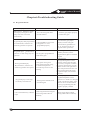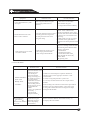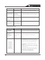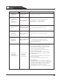
1
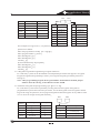
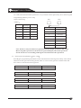
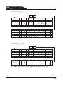
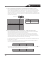
Installation Instruction
V 1.01
Products Manual
Content
Chapter 1 Product Introduction
1.Control panel wiring and system configuration
1.2Zone inputting port and connecting detectors
Chapter 2 System configuration and wiring
2.1 8 zones expansion module FC-7408
2.2 Single zone expansion module FC-7401
Chapter 3 Using and system setting
1.Keypad
1.2Keypad indicator
1.3Arming
1.4Disarm/silence alarm
1.5Force Arm
1.6Zone Bypass
2.System setting
2.1 Changing Date
2.2 Changing expiration date
2.3 Changing time
2.4 Auto Arm programming
2.5 Arm delay programming
2.6 Auto disarm programming
2.7 User password programming
2.7.1 Changing user password
2.7.2 Authority limits
2.8 System test
2.8.1 Zone test
2.8.2 Communication test
2.8.3 Time checking
Chapter 4 Programming
4.1 Enter Programming mode
4.2 Check program address
4.3 Enter value in program address
4.4 Default
4.5 Return to factory default
4.6 Exit program mode
4.7 Chart in the manual
Chapter 5 System Programming
5.1 General Control Programming
5.2 Zone Function Programming
5.3 Zone Programming
5.3.1 Procedure of zone programming
5.3.2 Zone Programming
5.4 Outputting Programming
3
4
6
8
8
9
9
9
9
11
11
12
12
12
13
13
13
14
15
15
16
16
17
17
17
17
19
19
19
19
19
20
20
20
21
21
23
24
24
24
25
26
Products Manual
5.5 Outputting and partition programming
5.6 Partition Programming
5.6.1 To determine number of partitions
5.6.2 To determine relation between partition and zone
5.6.3 Managing partition by keypad
5.6.4 Number and types of keypads
5.7 Zone Bypass Programming
5.8 Force Arming and Ground Fault Programming
5.9 Partition Programming
5.10 Arming Warning Programming
5.11 General Code limits Programming
5.12 Auxiliary Bus Output Programming
5.12.1 Data Stream Character Programming
5.13 System code and master code Programming
5.13.1 Changing Programming code
5.13.2 Changing Main Operation Code
5.13.3 Setting the length of main operation code
5.14 Telephone Alarm Warning Programming
5.14.1 Alarm Telephone Programming
5.14.2 Determine Communication Format
5.14.3 Phone Number General Control Programming
5.14.4 Determine User Code
5.14.5 Report Access Programming
5.15 Alarm Report Choosing Programming
5.15.1 Arm/disarm Report and Sending Option
5.15.2 Arm/disarm Report and Zone Report Option
5.15.3 Other Reports Option
5.16 Events Reports Code
Chapter 6 Trouble Shooting Guide
6.1 Keypad Trouble
6.2 Zone Trouble
6.3 System Trouble
27
27
27
28
28
28
29
32
32
33
33
34
34
35
35
35
35
36
36
37
37
38
38
39
39
39
40
42
42
42
43
44
Products Manual
Chapter 1 Product introduction
8 partitions: FC-7448 system can be distributed to 8 sub-zonesindependently, each of which
has its own keypad and ID code.Some of the keypads can be assigned as main system keypad
to control, process and arm/disarm allthe zones.
Zone: FC-7448 support 248 zones, 8 of which are original ones, the others are programmable
zones, any of which can follow one of all thefunctions of 15 zones.
Event memory: the maximum 400 events can be displayed in FC-7216K andsaved by turns of
time. For instance, arm/disarm, alarm and malfunction, 120 of which can be memorized.
Keypad programming: the system can be programmed by keypad with no needof expensive
handset programmer.
LCD icon programming: the title of every sub-zone and zones can be set as short message less
than 16 words and display on the LCD.
200 user codes: there are 200 four digits user codes, every of which can be set as super user
code to program all the user codes. All the user can be assigned to different limits to bypass,
test and arm/disarmexcept super users.
Auto arm/arm delay: arm every zones everyday is programmable, the super user can replace
auto arm time by arm delay, or assign a specific time to main control panel
Public partition: one partition can be programmed as the status of all the other partitions. Only
if all the other partitions armed, the public can be arm. In this way, it will protect public area
and keep the sub-zones independent.
Gas detector verification alarm: when the detector detects alarm signalfor the first time, the
system will restore, then if thereis alarm signal occurs within the confirm time, the system
will consider it as fire alarm, in this way, it can reduce false alarm and response as soon as
possible.
Force arming : the system can arm after bypass a group of zone according to programmable
arming setting, the replier is prior
3 telephone numbers: the system supports two 20-digit number, every partition or zone has a
3-digit or 4-digit ID code, and telephone can be set its own format and chose impulse or radio
frequency dialing, the second number is used to program remotely.
Output: the output are fully programmable and can activate by system events , or one or two
special zone of cross matrix; the output also can be usedto control otcal relay output module
or programmable address output in data bus
Two independent entry delay: while in zone programming, you can select either of the delay
in order to set the farther one from keyboard longer time to enter
Simple function key and super user interface: Enter one super user PIN, then press a function
key to arm, disarm and restore gas detector
Flexible data connection: the main panel is matched with most of the alarm receiver, support
4+2, contact ID etc.
3
Products Manual
Chapter 2 System Setting And Wiring Introduction
1. control panel wiring and system setting
FC-7448 is an alarm contol panel with fire and intrusion alarm system which is compatible with
many kinds of stealing detector and fire alarm detector. There are 8 zones which can be expanded to 40
zones by bus system. The expandsion equipment includes 8 zone expands ion module FC-7408 and
single zone expandsion module FC-7401and other infrared detector, door contact and smoke detector
etc with address The bus driver can adopt FC-7430B(single bus system) or FC-7432B(dual bus system)
Ground Liine
AC 6.5V
Siren Output
Auxiliary
power
supply
output
Backup power
B
Auxiliary output Bus
Keypad Bus
Alarm Telephone Port Porgrammable
output1
Programmable
output2
Self-take 8 zones
Panel wiring method
1.2 Wiring method the zone input prot and detector
Alarm zone input terminal
Open Circuit Alarm
4
Shorted circuit alarm
Products Manual
Normal detector has NO or NC output(general detector is C. NO), here the diagram take FC-7448 as
an example, with triggering method open or short circuit alarm The end resistors are supplied as
accessory, and different control panels have different end resistors. For example, the end resistor of
FC-7448 self-zoneis 2.2K, while the end resistor of expandsion module is 4.7K. Be sure not confuse
it when use.
LCD Keypad
FC-7448 Control Panel
8 zone module
Single zone module
8 Zone Module
Detector Detector
Detector
Detector
Detector
Other bus system
detector
Notes
Bus should be non-shield and non-twisted pair (RVV)
The thickness of bus results in the signal transmitting distance and quality, general main wire
adopts Rvv2*1.5mm, bus and other wires are suggested to wire separately, especially visual
intercom’s audible wiring, in order to avoid interference. If wiring bus through , it should
keep away from other wires. The max length of wire should be within 1.6 km, when it is out of
the limit, bus separator can prolong the length by 1.5km(RVV2*1.5mm). The most important
is to adopt more than one FC-7425, the n the bus length depends on the cable and circumstance.
The wire in building is always RVV2*0.5mm according to the requirement.
5
Products Manual
2 System accessories and wiring port defining
2.1 8 Zone expandsion module FC-7408
FC-7408 is a 8 zones expandsion module, which keeps 1.6m away from bus, and it has 30 self
FC-7408. FC-7408 requires DC12V supplied by FC-7448 control or independently, its static
voltage consumption is 10mA
A: port defining
Temper switch
Temper switch control pin
Address setting
dialing switch
8 zones input
Bus port
Power port
B.Wiring method
FC-7448LCD Key
B
FC-7448 Control panel
FC-7408
6
The max is 15
FC-7408
Detector
Detector
8
8
FC-7408
Detector
8
Detector
Other bus detector
8
Products Manual
Zone setting switch
FC-7408 has 8 zones, in means that the first FC-7408 expandsion zone is No. 9-16 zone, the second
is No. 17-24, the third is No.24-32 etc. When use more than one FC-7408 module, please refer the
method of setting dialing switch.
FC-7408B DIP switch
NO .
Expand zone
;Please preset how many zones to expand , how many modules to use, and distribute to which
zones (see the programming part)
The dialing switch should be precise, the end resistor is 47 k
7
Products Manual
2.2 Single zone expansion module FC-7401
FC-7401is single module with high stability and flexibility. Before installation, the dialing
switch will set the zone number, without additional power supply, and the static power
consumption is 350uA. FC-7401 is suitable for perimeter circumstance.
A
Wiring port
Zone
BUS wiring
Yellow
RED
Black BACK
B Method of setting address code
FC-7401 has 8 groups of manual dialing switches to set zone number. The step is to add the number
on the switch, the result is zone number. Also push the relative switch to ON position
C
1
2
4
8
16
32
64
128
1
2
3
4
5
6
7
8
Connect with control
B
8
Products Manual
Chapter3 Normal Using And System Setting
1.Keypad
ALARM LED
POWER LED
LCD display
Emergency/fire
Digital Keypad
Disarm/ arm
Safe/ perimeter
Bypass/reset
Confirm
Enter/Exit
programming
1.2 Keypad indicator
Indicator
OFF
Flashing
ON
armed(RED)
System is armed
Exit delay or alarm
System is armed
armed(Green)
Arming is activated
Zone is bypassed
System is ready
power(Green)
Power is cut off
System is defective
Current is normal
Control the keypad buzzer volume: press”1” and “*” simultaneously to increase, then press “4”
and “*” simultaneously to decrease
1.3 Method of arming
Before arming, the system should be prepared well, the keypad LED “POWER” and “ARM”
should light on and the LCD displays “arm is ready Ready to Arm ”.
Area
If there is a indicator is not on, the LCD will display “Arm is not ready”, please read “Force
Not Ready
arm” and “Zone bypass”.
Area
There are 5 standard arm method listed as follow chart
9
Products Manual
Arm type
Operation
Nromal Arm
(Nobody at spot
entry/exit
delay active)
Superuser
password
[1234]
+
Arm
1.Red LED flash
2.FC-7216K keypad display"(Armed )
3.Within exit delay period, FC-7216K
displays (Exi t Now)
4.Beep
5.Red LED on when exit delay expire
Supter user
password
[1234]
+"security
+
perimeter
1.Red LED flash
2. FC-7216K key displays
(Perimeter Inst)
3.Within exit delay period FC-7216 keypad
displays ( Exit Now )
4.Green LED is on
5.Beep
6.Arm the protection zones
7.Red LED is on when exit delay expires
8.Yellow LED is on when exit delay expires
Perimeter arm
(Nobody at
spot, ectry/
exit delay is
active)
Super user
password
[1234]
+
Perimeter
1.Red LED flashing
2.FC-7216K keypad displays
( Perimeter On)
3.Within exit delay period, FC-7216K
keypad displays ( Exit Now )
4.Green LED is on
5. Beep
6.Arm outdoor protection zones
7.Red LED is on once exit delay expires
8.FC-7216K keypad yellow LED is
on once exit delay expires
Special arm
(the program
address is
0183
0183 )
Super user password
[1234]
+
[#]
+
[4]
1.Red LED flashing
2.FC-7216K keypad display
( On Partial)
3.On exitdelay, FC-7216K display
( Exit Now )
4.Green LED is always on
5.Beep
6.Red LED is on when exit delay expires
Max security
arm
(nobody at
spot,entry
delay is
unefficient)
Super user
password
[1234]
+
security
+
arm
1.Red LED flashing
2.FC-7216K keypad display
(Armed Instant)
3.During exit delay period, FC-7216K
keypad display (Exit Now)
4.Beep
5.Red LED is on once exit delay expires
Peimeter arm
(Somebody at
spot, entry
delay is
unefficient)
10
Response
Solution
Exit within
exit delay
period
Move freely
within
protection
area
Move freely
in protection
area
Exit within
exit delay
period
Exit within
exit delay
Warning do not
disturbe zone
once exit delay
Products Manual
1.4 Disarm /delete alarm
Please read solution part in case of emergency occuring
entry, please disarm as following chart.
If there a pre-alarm indicator while
Warning: If bell or siren sounding, or red LED for armed flashing, the keypad will alarm
before people arriving. FC-7216K will display
( Zone Alarm ) . During entry delay,
keypad will sound impulse, not continuous sound as usual. If the alarm address is not
confirmed, keep away from zone only if along with right person.
Disarm
Operation
Response
Super user password
[1234]
Disarm
+
[Disarm ]
Super user password
Delete alarm
[1234]
+
[ Disarm]
Red LED off
Pre-alarm indicator off
Alarm stop
When alarm stops,FC-7216K
keypad will disply
(SounderSilenced ) till
system restore
1.5 Force arming
If there is malfunction or FC-7216K display"Not ready", user can force arm the system by
bypassing malfunction(if programmed).
Force arming when current cut: if current cut, it is not allowed to arm as usual, force arm as a
warning to show the control panel using backup battery.
Warning: force arming or bypassing skip some protection steps as it disregarding violated
zones when arm, so some signal will not be detected or delay. As a result, it must release
unneccessory defection (closed door or windows) If can not, please contact with
installation company
Note: If there is malfunction, please refer to Zone bypass
part
Command Sequence
Enter code
to arm,
master user
password
+
Arm
Response
The keypad will display
as follow after beep for
5s
To force arm
press BYPASS
There is trouble zone
in control panel, if
there is three wrong
voice, it means that it
is unacceptable or not
allowed force arm
Probable Solution
Press "Bypass"
for 5s when beep
Response
The keypad will display as
follow during exit delay and
the red arming indicator
"
On Partial
Area X
Control Trouble
There will be bypass
trouble zone, it means
unacceptable or not allowed
force arm when there is
three wrong voice
11
Products Manual
1.6 Zone bypass
Before arming, it need to bypass some zones temporarily.
For example:a open window will cause FC-7216K display "Not ready" Only bypass one zone
every time, so user need to operate one by one.
Bypass type
Operation command
Bypass
violated
zones
Super user password
[1234] +
[bypass][xxx]
( zone Number )
Display
bypassed
zones
Superuser password
[1234] +[bypass]
FC-7216K keypad display
" Bypass and bypassed
zone No
Delete single
bypassed
zones
Superuser password
[1234] +[bypass][xxx]
( Zone Number )
Delete single bypassed zone
Superuser password
[1234] +[bypass]+[*]
Delete all the bypassed zone
Delete all the
bypassed zones
Response
Solution
When arming,
it need to
bypass input
zones
If zone not intervened
ARM indicator
will flash
Note: 1.Read “force arm” part to gain other methods of bypass
2. Zone Number should be 3-digit, for example, 002,003
063
122
etc
3. When system armed, except for 24- hour zone, the bypassed zones should be
deleted. When delete 24-hour zone bypass , user can adopt either of the above
method. If bypass zone on keypad, it is necessary to adopt single partition
method.
2. System settig
2.1 Changing the date
For example: change the date to "12/17/2006" as following chart:
Steps to change the date
Enter the superuser password
Enter
12
2
Command sequence
[1234]+[#][0]
[2]
If Accepted, the Display Reads
0 1 2 3 4 6 8 setting
Enter month (01
Enter Day(01
12
31)
Enter the month 12
[12]
Enter the date”17”
[17]
Enter year(XX) and press
“#”to confirm
Enter the year “06”
[06]+[#]
Month Date Year A long beep
signifies acceptance
Products Manual
2.2 Changing the Temporary PIN Expiration Dta
This chart explais the produre for changing the expiration date (for temporary PIN) at the keypad
For example: change the date to "06/06/2006" as following procedure
Steps to Change the exp Date
Command Sequence
If accepted, the Display Reads
Enter superuser password
[1234]+[#][0]
0 1 2 3 4 6 8
Enter setting code 3
[3]
Enter month (01
Enter thedate 06
[06]
Enter Day(01
Enter the month
“06”
”
[06]
Enter the year “06”
[06]+[#]
12
31)
Enter year(XX),and press “#” to confirm
Month, Date, Year A long beep
signifies acceptable
2.3 Changing the time
For example, change the time to
4:23 PM, Wednesday as following procedure:
Steps to change the time
Command Sequence
Enter superuser password
[1234]+[#][0]
Enter time setting code “6”
[6]
Enter Day (1
[4]
Enter Time(0100
Enter the day 4
Enter time 04
23
[04] [23]
Enter AM or PM
Enter 6
2. Enter Time(0100
1259
,
0 1 2 3 4 6 8
7
1259)
Enter AM/PM(4/6),and press “#”to confirm
Enter Day(1...7) Time AM/PM
A long beep signifies acceptances
[6]+[#]
Note: 1. The day should between 1to 7,
If acceptable, the display reads
1
for Friday, “2” for Monday, etc.
0100” for hour
1259
for minute
2.4 Automatic arming
Each partition can be programmed to automatically arm once per day.
To inform occupants that the system is about to arm, a pre-arming period will begin before the
system arms automatically. The keypad sounders, and any outputs programmed to follow the
keypad sounders, will pulse five times every minute if programmed to do so. During the last
five minutes before arming, these sounders will be on steady. Once per minute the keypad will
read,"Arm in NN min/PIN+OFF-extend" If automatic arming is used to in Master Keypad mode,
it will affect all the partitions you have access to. If used in single partition mode, or from a
single partition keypad, it will affect only the partition you are working in. During the pre-arming
period, perform the following steps to set delay arming:
13
Products Manual
Steps to changing time
Response
Enter superuser password
[1234]
Press "Disarm"
Arming time will be pushed to 30mins later, a new
pre-arming period will begin 15mins before the system
armed automatically
Setting the Automatic Arming Time as following:
Setting the Automatic
Arming Time
Enter Master PIN +[#][0]
Sequence
[1234]+[#][0]
Enter a 1 to enter the
Automatic Arm Setup
programming
Enter Partition number
Press [#] to exit
Enter a time for each
day.
Enter I [0][1][0]03]
0 1 2 3 4 6 8 setting
Sunday -- 00
[1]
[X]+[#]
[00]
LCD Displaying
[00]+[#]
00
If programming is done from a Master Keypad
that is not in single mode, the user will be
prompted to enter the partition they wish to
program
The display will start with Sunday. It will read,
"Sunday-nn". Enter the time in 24 hour format
then press the [#] key. If you make a mistake,
press the [*]key twice to move back to your
last entry
For example:
12 midnight =2400# 12 noon=1200#
12:01 =0001#
12:01 pm=1201#
1:00 am = 0100#
1:00pm =1300#
Disable =0000#
2.5 Setting Delayed Arming
Delayed arming is to arm the system after a specified number of hours
For example: arm the system after three hours
Steps to change time
Enter superuser
password+[#][99]
Enter the number of hours
to delay arming 03
Command
[1234]+[#][99]
[03]+[#]
The Display Reads
Arm in 00 Hours # to accept
A long beep signifies acceptance
Note
1.Delayed arming can be used even if there are no automatic arming times programmed.
If programme the delay arming at master keypad, it will affect all partitions you have
access to. If used in single partition mode, or from a single partition keypad, it will affect
only the partition you are working in.
2.Delay arming will override automatic arming
3.Delay arming will also provide a 30 minute pre-arm period like the one provided with
automatic arming.
14
Products Manual
2.6 Setting Automatic disarming
Each partition can be programmed to automatically disarm once per day
To programme the Automatic Disrming Time, perform the following steps
Steps to changing
expiration date
Command
Enter superuser password
[1234]+[#][0]
Enter Automatic
disarming code”4”
[4]
Enter partition
No and press "#"
to exit
Enter time for disarming
Automaticlly
[X]+[#]
[00]
[00]+[#]
If acceptable, the display reads
0 1 2 3 4 6 8
Sunday -- 00
00
If the programming keypad is not single
partition format, user should enter which
partition to programme.If keypad is single
partition format, please skip it.
Display will start from Sunday, it will read "
Sunday-hour:minute",input time and press"#"
to continue the next day, press"*" two times
return to previous day
For example:
Noon12:00 =12:00# Midnight 12 :00=24:00#
AM 12:01=00:01#
PM 12:01=12:01#
AM 1:00=01:00#
PM 1:00=13:00#
Cancel = 00:00#
2.7 Setting user password
2.7.1 General Information
1.(User Number) it is used to identify user's number, the maximum number is 200(001-200)
2.(PIN) it is 4-digit code users must enter at the keypad to gain access to the system
3.( Authority Level ) this number determines which function each it will be able to perform
4.Your system has the capability to assign up to 200 PIN, each four digits long. Each User
Number can have only one PIN assigned to it. Attempting to assign the same PIN to multiple
User Numbers will result in the three-beeperror tone, and the entry will not be made.
5.User Number 001is designed as a Master code. It can be used to add, delete, or change other
PIN. It will always have access to all partitions regardless of how it is programmed.
6.Users Number 001is shipped from the factory with the PIN of 1234.This PIN can be changed
to one of your personal preference and must be programmed as a Master code
Warning: PIN should never be programmed with common sequences such as 1234 ,1111, or
2468 because they are easily violated.
15
Products Manual
2.7.2 Changing PIN
This chart will explain how to change PIN
For example set"028"as the Unlimited User Number in third partition, and PIN is
2005
as following
Steps to change a PIN
Command Sequence
If accepted, the Display will Reads
Enter superuser PIN
[1234]+[#][0]
0 1 2 3 4 6 8
Enter specified code 0
[0]
Enter user number
[028]
Enter the User Number
[1]
Enter the Area(s)/partition(s)
this user has access to and
press”#” to confirm
[#]
Enter Next Area End With #
Enter PIN
Enter the PIN
[2005]
Enter PIN again End With #
Enter the PIN again followed
by the “#”key
[2005]
Enter User NO. (001
200
Enter Authority level(0
Enter Area(s) Or
#
6)
Of All
2.7.3 Authority Limits
0 =Super user Can enter all commands, add or change PIN s in assigned partitions,
change time and date, bypass, arm, disarm, perform system tests, system reset, and view history.
Any or all PIN can behave as a Superuser 1 =Unlimited: Can enter all commands, bypass,
arm, disarm and perform system tests. Can not change PIN
“2 ”=General: Can bypass, arm, disarm. Can not change PIN and reset system, or enter
command 7 or any of the command 8 functions. Bypass and disarm are programmed by partition.
“3 ”=Arm Only
Can arm the system only. Can not perform any other functions including
disarming.
“4 ”=Temporary
Valid only for a specified time(PIN will disappear upon expiration date).
Can arm or disarm the system, but can not perform any other functions. If this function is
performed from a Master Keypad, you must be in Single Partition Mode
“5”=Duress
When the system is disarmed using the duress PIN, a silent report is sent to the
central station. The Duress PIN is intended to be used when the user is forced to disarm the
system
“6 ”= Access
When a PIN with an Access code is entered, any output programmed for
Access Output will pulse on for 10 seconds.
16
Products Manual
2.8 System Test
2.8.1 Zone Test
The Zone Test is used to confirm that detectors will report alarms. System test works on all
zones, except24-hour zones and fire zones. During the test, keypad not report alarm.
Type of Test
Zone Test
Command
Super user
PIN
+
[#][81]
Response
FC-7216K keypad display: “ ( Test
Zone ) followed by the zone
number of any zones that have not
been tested FC-7216K keypad
display
( Now Testing )
followed by the zone number of
zone that is currently being tested.
It returns to (Test Zone) after
violation
Solution
Test each detector one at
a time as instructed by
the installing company
To exit the Zone Test
mode ,enter your PIN+#
Note:This test not be performed from a Master Keypad
2.8.2 Communication Test
This test is available only if the system has been programmed by the installing company to
permit communicator test. A long beep will initially sound to acknowledge the start of test.
If the test is successful ,t he souner will return to arm status .To silence the sounder, enter
your PIN followed by"#"key or press "*"
Test Type
Required address
0329,0504,0529
,1521
Command
Super user
PIN
+
[#][82]
Response
1.A long beep will sound
2.A Test report is sent
to the monitoring service
Solution
If the test fails, the
keypad sound will sound
continuously To silence
the sounder, press the
"System Reset" key
Note: This test will take
several munites to
complete as the control
will try 10 attempts
before it fails this test
2.8.3 Event History Readback
The History Buffer stores the last 400 events in memory, the most recent 100 are stored in
non-volatile memory(will be kept even if total power loss) FC-7216 keypad can display as
following:
17
Products Manual
Test Type
Command
Event history
readback*
Super user
PIN
+
[#][89]
Note:1.
*
Response
FC-7216K keypad display
the most recent events
Solution
FC-7216K keypad
press[ 9 ] [ 6 ] and
[ # ] key, it will
display all of the
events Press “*” to
exit
Means that it should be in Single Partition Mode if this test is performed at
master keypad
2.FC-7216K keypad : It will display all the history events. Press”#” to start and
continue to read back the next event. The”9” key will scroll you back through the
history line by line. The “6” key will scroll you back up through the events by
events. Each event consists of two or three lines or display screen. The first line/
screen will be the event title and user. The second line/screen will be the date of the
event or the change being made. If there is third line/screen, it will be the date of
the change. To exit the Event History Mode, press the “*”key or wait 20 seconds
and the keypad will exit automatically. When performing this from a Master
Keypad, each partition will display its own history.
18
Products Manual
Chapter4 Programming
4.1 Entering the Programmer’s Mode
To enter the Programmer's Mode, enter the system password followed by "#" and "0". Shorting
the program pads on the control panel will also activate Programmer's Mode. The default
system password is [9][8][7][6]
4.2 Reading back a Program Address
Once you are in the programmer’s mode, to read back the value of a Program Address, enter
that Program Address followed by”#”. Each data digit is displayed one data at a time. To view
the second data digit, enter the “#”button again.
The display will look like this:
Prog
D01=1
Adr .=0000
Program address
Version Number
4.05
Mode
Data digit number Value of data digit
4.3 Enter in a value in a Program Address
To enter a value in the Program Address, enter the Program Address, then enter the value for
each Data Digit, then enter “#” to save it and move on to the next Program Address. Entering
data digit 1 will increment you to the next data digit.
The display will show the Program Address
and will display the value of each Data Digit afer you enter it. The data will be saved when you
press the “#” key. The control panel will automatically increment to the next program address
If you wish to program that next address, enter the necessary information.
If you wish to read back the value of that address, press “#” key
If you wish to program a different address, press “#’key two times and enter the program
address you wish to program.
If you make a mistake at any time, press the “*’key two times. This will clear the display,
allowing you to enter the program address you wish to work with..
Note: Entering HEX Values
Some data values will be higher than 9. These values must be programed by pressing the
“#” key followed by some other number. These values will display as HEX characters(A-F)
when entered. Example: entering “*” “0” at the keypad will display an “A”.
The HEX character values are as follows:
*0=A
10
*1=B
11
*2=C
12
*3=D
13
*4=E
14
*5=F
15
4.4 Default
The FC-7448 is shipped from the factory as a working, pre-programmed control. Many of the
programming address may already be set to the values you need. The default values are shown
in Reverse Print If the value you woule like is in Reverse Print, you do not need to pre-program
this address. In the example below, a “0” is the default value:
19
Products Manual
0
1
2
3
4
5
6
Feature1
Feature2
Feature3
If the default is not shown in reverse print, it will be shown in a separate table.
4.5 Setting the Control to the Factory Default
Only enter [0][1][#] in Program Address 4058 when you are completely sure you want to erase
all installer programming. Entering [0][1][#] in Program Address 4058 will immediately
reset the control to the factory default. Any programming already done by the installer will be
erased.
Waring: This action can not be reversed.
4.6 Exiting the Programmer’s Mode
To exit the Programmer’s Mode, press the “*” for a minimum of 4 seconds. If not keypad entries
are made for 4 munites, the control panel will automatically exit you from the Programmer’s Mode
4.7 Understanding the programming charts
The Programming Reference Guide makes ususe of three types of charts. Each is decribed below
If the chart looks like this, a combination of feature is available to be programmed for that
particular address.
Select
Option1
Partition2
Partition 3
Partition4
0
1
2
Enter the Data Digit as a :
3
4
5
6
Identifies the options/features
availbale for this address
7
Enter one of these
numbers for the
appropriate
data digit
represents which options/feature are
included with each selection
For example: To select Feature 2 only, enter
the data digit as a 1 To select Feature2 and
Feature 4,enter the data digit as a 5
If the chart looks like this, only a feature is available to be programmed for that particular address.
Select Option
Cancel Function
Represents the option/feature available
for this address.
Example: To select Disabled, enter
the data digit as a 0.To select Entry/Exit
Data
0
Perimeter Instant Zone
1
Exit/Entry Delay zone1
3
Exit/Entry Delay zone2
4
Delay#2, enter the data digit as a 4
Enter one of the numbers for the appropriate data digit
20
Products Manual
Default chart that looks like this
Zone Function
Address
Default
1
0001
23
2
0002
24
3
0003
21
Entering data digits in Prograrmming Address
Prog
4.05
Mode
0
D02=
D01=1
Adr .=0000
Select option
D01=
1
2
Data
3
4
5
6
7
Perform1
Perform2
Perform3
Perform4
0
1
2
3
4
5
6
Perform1
Perform2
Perform3
21
Products Manual
Chapter5 System Programming
5.1 General Control Programming: Program Address
0000
General control programming defines the system-wide general operating parameter
Example: To program the system-wide General Operating parameters as: allowing Normal
and Custom Arming. Operating at 50Hz, and to Restore when a Zone restores.
Refer the data in following char to program D01=3 D02=1
To enter programming mode [9 8 7 6][#][0]
Enter Program Address [0 0 0 0]
Enter data digit01 [3]
Enter data digit02 [1]
Confirm [#]
Entering Data
Select Options
0
1
2
3
4
5
6
7
8
9 *0 *1 *2 *3 *4 *5
Normal and Custom Arming
Perimeter Instant Arming
Perimeter Arming
Max Security Arm
D01
D02
Answering Telephone Setting
It will alarm when there is
malfunction in silent alarm zone
Work Frequency: 50HZ
Work Frequency: 60HZ
Select Option
0
1
2
Entering Data
3
4
5
System reset if buzzer silence
System reset if zone reset
Zone reset when disarm
Flexible bypass
Note:1. Normal Arming=”PIN”+”ON”, if programmed, Normal Arming arms the entire
system while allowing entry delays for entry/exit zones
2.Perimeter Instant Arming=”PIN”+”No Entry””Perimeter Only” if programmed,
Perimeter Instant Arming arms only the perimeter of the system and doesn’t allow
entry delays for entry/exit zones
3.Perimeter Arming= “PIN”+”Perimeter Only”, if programmed, Perimeter Arming
arms only the perimeter of the system and does not allow entry delays for entry/exit
zones.
4.Custom Arming= “PIN”+”#””4”, if programmed, Custom Arming allows custom
arming of the system and bypass the zone functions specified in program address
0183
5.Maximum Security Arming= “PIN””No entry””On”, if programmed, Maximum
Security Arming arms the entire system and does not allow entry delays for entry/
exit zones
22
Products Manual
5. 2 Programming the Zone Function
Program Address
0001~0030
A zone Function is the description of how a zone will behave. Up to 30 different Zone Functions
may be programmed. You may use the default values(which are already programmed into the
panel) and skip this step, change the defaults or add new Zone Functions
Example: To program Zone Function as: Steady Alarm Output, Alarm on Short, Trouble on Open
, Perimeter Instant Arming
Data Digit1=”6”, Data Digit2=”7”
Enter Programmer Mode [9 8 7 6][#][0]
Enter Program Address [0 0 0 1]
Enter Data Digit 01 [6]
Enter Data Digit 02 [7]
Confirm [#]
Enter Data Digit
Select Options
0
1
2
3
4
5
6
7 *2 *3 *4 *5
Invisible Alarm
Steady Alarm Output
Pulsing Alarm Output
Alarm On Short
Alarm on Open
Short/cut circuit trouble
work frequency 50Hz
work frequency 60Hz
D01
Select Options
Note: when Data 02 value is
9
,
Data digit 01 represents as follow
Select Option
Single zone arm/disarm can not force arm
Single zone arm/disarm can force arm
All the zone arm/disarm force arm is not allowed
All the zone arm/disarm (Force arm is not allowed
Data
0
1
2
3
D02
Data
Delete Function
0
Perimeter Instant
1
24 Hours Zone
2
Exit/Entry Delay 1
3
Exit/Entry Delay 2
4
Internal Exit/Entry Follow
5
Internal Stay/Away
6
Internal not instant
7
Day Monitor
8
Arm/disarm Zone
9
Fire with verification
*0
Fire without verification
*1
Delete Exit/Delay Delay 1 zone
*4
Delete Exit/Entry Delay 2 zone
*5
23
Products Manual
Zone Function Address
Default
Meaning
01
0001
23
Steady alarm output alarm on short or on open
Entry/exit delay
02
0002
24
Steady alarm output, alarm on short and open
03
0003
21
Steady alarm output, alarm on short and open, Perimeter instant alarm
04
0004
25
Steady alarm output, alarm on short and open
05
0005
26
Steady alarm output, alarm on short and open, interior homeaway
06
0006
27
Steady alarm output, alarm on short and open, interior instant
07
0007
22
Steady alarm output, alarm on short and open, 24-hour zone
08
0008
7*0
Pulse alarm output , alarm on short/open trouble on open
verification
Entry/exit delay2
Interior entry/eixt follower
Fire zone with
Note: Other zones function are all instant alarm, alarm on short and open, perimeter instant
Chart1: Zone function Default
5.3 Zone programming: Program Address
0031~0278
5.3.1 Steps to program zone
confirm zone function
determine which zone has which type of function
Determine the zone specification adopt which type of expansion
We suggest that you record all the zones need to program in case of confusion
5.3.2 Zone Programming
FC-7448 has 248 zones
program address is
0031-0278
each address has one relative
zone .
For example: set the No.22 zone belonging to Partition 1 followed by zone function 1 inputting
D01=0
D02=1
Enter Programmer’ Mode [9 8 7 6][#][0]
Enter Program Address
Enter Data digit 01
[0]
Enter Data digit 02
[1]
Confirm [#]
24
[0 0 52]
Zone Default
Zone No.
1
2
3
4
5
6
7
8
9-248
Address
0031
0032
0033
0034
0035
0036
0037
0038
0039-0278
Default
01
02
03
04
05
06
07
08
00
Products Manual
There are 248 zones from Address 0031
D01
0278
D02
each of address has two data digits represents
Zone
Function No
Program
Address
01
0001
23
02
0002
24
03
0003
21
04
0004
25
05
0005
26
06
0006
27
07
0007
22
08
0008
7*0
09-30
0009-0030
23
Zone Function No.
Default
01
30
5.4 Output program 2734~2736
There are three programmable outputs on FC-7448 control panel:, Bell/ Output1/Output2
system status output and event output not followed by system event program as follow
Data
Select Option
0
Any alarm is locked
1
2
Entry pre-alarm is connected
2f pll l Systen+Reset
restral after 10s being conncted
3
Connected when arming
6
Zone Alarm
9
Exit control ,output pulse for 10s
*0
Wireless remote controller
Select Option
Data
Cancel
0
All Arming
1
Partial Arming
2
Independent Arming
3
Data
Select Option
0
Cancel function
1
Burglar
2
Fire
Burglar and
Fire Alarm
3
Select Option
Data
Instant Output
0
Locking Output
1
Instant Output
2
Locking Output
3
25
Products Manual
Each output address
Output
Address
Default Value
Bell
2734
63
Output 1
2735
33
Output 2
2736
23
FC-7448 the Bell output is used to output alarm indicaition input data 633
Note: if use commercial fire alarm, it is always supplied by Output 22, and it can
restore detector by enter PLN+”Reset” once fire alrm output alarm signal
5.5 Output followed by partition setting
2737
2738
FC-7448 can be distributed to eith partitions, the three outputs can be programmed to follow
with relative output on one partition
Output and Address
Outputs
Address
Default
Bell
2737 Digit 1
8
Output 1
2737 Digit 2
8
Output 2
2738
8
Digit1
Note the digit of address
2738 should be 0
D01
D02
Entering Data
Option
0
Belong to Partition1
1
Belong to Partition2
2
Belong to Partition3
3
Belong to Partition4
4
Belong to Partiton5
5
Beong to Partition6
6
Belong to Partition7
7
Belong to Partiton8
8
Belong to all Partiton
D01
D02
Wireless Remote
Data
Option
0
Cancel
1
BELL output
2
Output1
3
Output2
Example: To set output BELL follow fire burglar alarm output in partiton 2 as follow:
Enter :[9876][#][0] Enter Program Mode
Enter :[2734] [63][#] enter 63 at address2734 to follow fire/burglar alarm
Enter :[**] Press “*” two times to input address once again
Enter :[2737][18][ ] enter 1 in first data digit on Address 2737 to show Bell belong to
Partition 2
Press * for 5 seconds to exit
26
Products Manual
5.6 Partition Programming
FC-7448 can be distributed to eight partiton s with function zones which arm/disarm
independently. Before programming, three factors should be determined, the number of zone
s need to programmed ,if public zone exits, and ,
5.6.1 To determine the number of zones the system will operate, and if there is public partition
programming address(3420)
Public partition is the zone can be armed only if other relative zone armed, while other relative
zones can be disarmed only l if it disarmed In address 3420, the first data digit represents the
number of zones, the second data digit determine the relation between public zone and other
zones. It is need not to set public zone if without special requirement by not entering value in
second data digit.
D01
Entering data
Meaning
D02
Option
Entering data
0
Partition 1
No public partiton
0
1
Partition 2
Zone1 is the public zone for Zone2 and zone.3
1
2
Partition 3
Zone1 is the public zone for zone 2 to zone 4
2
3
Partition 4
Zone1 is the public zone for zone 2 to zone 5
3
4
Partiton 5
Zone1 is the public zone for zone 2 to zone 6
4
5
Partiton 6
Zone1 is the public zone for zone 2 to zone 7
5
6
Partition 7
Zone1 is the public zone for zone 2 to zone 8
6
7
Partiton 8
5.6.2 To determine which zone belonged to which partiton 0287-0410
It means that there are 248 zone totally and 8 independent partitions, then you need to distribute
all the zones to 8 partitions from address 0287 to 0410, every of which has two digits on behave
of 248 zones. If enter different data value to every data digit, it represents the zone belong to
relative partition.
27
Products Manual
D02
D01
Data digit 2
Address
Data digit1
0287
No.1 zone
No2 zone
0288
No.3 zone
No.4 zone
0289
No.5 zone
No.6 zone
0290
0410
No.7 zone
No.247 zone
No.8 zone
No.248
Data
Representation
Data
Representation
0
Partition 1
0
Partition 1
1
Partition 1
1
Partition 1
2
Partition 1
2
Partition 1
3
Partition 1
3
Partition 1
4
Partition 1
4
Partition 1
5
Partition 1
5
Partition 1
6
Partition 1
6
Partition 1
7
Partition 1
7
Partition 1
For example:to assign zone 1,2,3 to partition 1 and assign zone 4.5.6 to
partition 2 as follow:
Enter the programmer's mode [9 8 7 6][#][0]
Enter program address [0 2 8 7]
Enter data digit01 [0]
Enter data digit02 [0]
Confirm [#]
System automatically skip to[0288]
Enter data digit01 [1]
Enter data digit02 [1]
Confirm [#]
5.6.3 Keypad Assignment Programming: Program Addresses
FC-7448 alary system can be distributed to 8 independent partitions and support 15 keypads.
Keypad Assignment Programming is where you assign the keypad type and the partition it
belongs to.
Note: when programming keypad, the keypad Number should match with the jumper
address on PCB, refering to introduction on FC-7216K
5.6.4 Number of keypads and programming type 3131-31-38
FC-7448 alarm system can be operated by one keypad or more keypads. If keypad are
programmed to operate more than one partitions, one of the keypads can be assigned as master
keypad. If using one partition, do not program keypads as Master Keypads. Every address from
3131 to 3138 can assign two keypads function
D01
28
D02
Address
Data digit 1
Data digit 2
3131
Keypad 1
Keypad 2
Enter data
Select Option
3132
Keypad 2
Keypad 3
0
No use
3133
Keypad 3
Keypad 5
1
LCD Display
2
LED Display
3138
Keypad 15
0
3
LCD display& Master
Products Manual
FC-7448 can be distributed to 8 partitions, every of which can be operated by one or more keypads
Programming address:[3139-3146]
Steps as following:
D01
D02
Address
Address
Data digit2
Data digitl
3139
Keypad 1
Keypad 2
Entering data
Functiion
3140
Keypad 3
Keypad 4
0
Partition 1
3141
Keypad 5
Keypad 6
1
Partition 2
2
Partition 3
3
Partition 4
4
Partition 5
5
Partition 6
6
Partition 7
7
Partition 8
3146
0
Keypad 15
Note: If there is only one Master keypad and control multiple partitions, and assign
Master keypad to partition 1, the master keypad will display when other partiiton
alarm but buzzer not sounding, although it can arm/disarm other partitions
2.6
Zone bypass Programming
2721-2724
Zone Bypass programming determines which zone functions can be bypassed. Only zones whose
function can be bypassed can be bypassed, other or, it can not be bypassed. 24 Hour Zones and
Fire zones are not allowed to be bypassed.
Address
2721
Address
2722
Address
2723
Digitl
Zone Functionl-4
Digitl
Zone Function9-12
Digitl
Zone Function17-20
Digital2
Zone Function5-8
Data2
Zone Function13-16
Data2
Zone Function20-24
Address
Digitl
Digit2
2724
Zone Function25-28
Zone Function29-30
29
Products Manual
Program Address
2721
D02
D01
Bypassable zone
0
l
2
3
4
5
6
7
8
9
*0
*1
*3
*4
0
l
2
3
4
5
6
7
8
9
*0
*1
*3
*4
Zone Func.1
Zone Func. 2
Zone Func 3
Zone Func 4
Bypassable zone
Zone Func.5
Zone Func 6
Zone Func. 7
Zone Func. 8
Program Address
2722
D02
D01
Bypassable zone
0
l
2
3
4
5
6
7
8
9
*0
*1
*3
*4
0
l
2
3
4
5
6
7
8
9
*0
*1
*3
*4
Zone function 9
Zone function 10
Zone function 11
Zone function 12
Bypassable zone
Zone function 13
Zone function 14
Zone function 15
Zone function 16
30
Products Manual
Program Address
2723
D02
D01
Bypassable zone
0
l
2
3
4
5
6
7
8
9
*0
*1
*3
*4
0
l
2
3
4
5
6
7
8
9
*0
*1
*3
*4
Zone function 17
Zone function 18
Zone function 19
Zone function 20
Bypassable zone
Zone function 21
Zone function 22
Zone function 23
Zone function 24
Program Address
2724
D02
D01
Bypassable zone
0
l
2
3
4
5
6
7
8
9
*0
*1
*3
*4
0
l
2
3
4
5
6
7
8
9
*0
*1
*3
*4
Zone function 25
Zone function26
Zone function 27
Zone function 28
Bypassable zone
Zone function 29
Zone function 30
Note: 24 Hour Zone Function and Fire Zone Function can not be bypassed
31
Products Manual
5.6 Force Arming and Ground Fault Detect Programming: Program Address
2732
Force Arming programming defines how many zones may be Force Armed using an Arming
sequence followed by the [Bypass] key. With this entry, all violated zones (up the programmed
limit ) will automatically be Force Armed ( bypass ). Ground Fault Detect programming
determines whether or not the control will detect a ground fault condition. The Maximum zones
Number can be force armed is 9. If the function of Ground Fault Detect be programmed, keypad
will display”Ground Fault”.
D01
D02
Address:2732 =
Select Option
Data Digit
Do not allow Force Arming
Allow up to 1 zone to be force Armed
Allow up to 2 zones to be Force Armed
0
1
2
3
4
5
6
7
8
9
Allow up to 3 zones to be Force Armed
Allow upto 4 zones to be Force Armed
Allow up to 5 zones to be Force Armed
Allow up to 6 zones to be Force Armed
Allow up to 7 zones to be Force Armed
Allow up to 8 zones to be Force Armed
Allow up to 9 zones to be Force Armed
5.9 Entry/exit Delay Programming
Program Address
Data Digit
Select Option
0
Ground Fault Detect Off
1
Ground Fault Detect On
4028--4030
4032--4033
Entry Delay determines the system not alarm within delay period once the zone be triggered
and not disarm(if programmed), until the delay period expires.
Exit Delay determines the system will not alarm within exit delay period until exit delay
expires once he zones ( except 24 Hour Zone and Fire Alarm) be triggered (if programmed)
Alarm bell time determines the time to output alarm followed by system alarming. Fire alarm
time determines the time output alarm followed by system alarming.
FC-7448 has exit delay, entry delay 1 and entry delay 2, Fire alarm time and burglar alarm time.
Program address is as follow:
1.Exit delay: two data digits determine time (5 seconds per unit),data should from [00-51]
(0-255 seconds)Preprogramed data is 12(60 seconds)
Exit delay
Address 4030
Data l
Data 2
1
2
2.Entry delay 1: two data digit determine time (5 seconds per unit), data should between [0
0-255 seconds Preprogrammed value is 09 (45 seconds).
32
Entry delay 1
Data l
Data 2
Address 4028
0
9
51]
Products Manual
3.Entry delay 2 two data digits determine time ( 5 seconds per unit ) enter data from 0 to 51
0-255seconds) Preprogrammed value is 09 45seconds
Entry delay 2
Data l
Data 2
Address 4029
0
9
4.Fire alarm time two data digits determine time(one minute per unit), enter data 0-99
0 99minute) Preprogrammed value is [04](4 minutes).
Fire alarm time
Data1
Data 2
Address 4302
0
4
5.Burglar alarm time two data digits determine time (one minute per unit), enter data [0
0 99minute Preprogrammed value is [04](4 minutes)
Burglar alarm time
Data 1
Data 2
Address 4033
0
4
99]
5.10 Arming Warning Programming: Program Address 3425--3428
Arming Warning programming defines whether the keypad will be audible during the exit
delay auto arm period. If programmed, the keypad sounder and 5 seconds remaining, the
keypad sounder will active 3 times. During auto arming, a pre-arming period will begin
15 minutes before the system arms automatically. The keypad sounders will pulse five times
every minute. During the last five minutes before arming, these sounders will be on steady.
D01
D02
Data 1
Address
3425
Partition 1
3426
Partiition 3
3427
Partition 5
3428
Partition 7
No keypad sounder 0
Keypad sounder4
No keypad sounder 0
Keypad sounder4
No keypad sounder0
Keypad sounder 4
No keypad sounder0
Keypad sounder4
Partition 2
Partition 4
Partition 6
Partition 8
Data 2
No keypad sounder, enter 0
Keypad sounder, enter 4
No keypad sounder, enter 0
Keypad sounder, enter 4
No keypad sounder, enter 0
Keypad sounder, enter 4
No keypad sounder, enter 0
Keypad sounder, enter 4
Note: The factory default is [0] with no keypad sounder during Exit delay
5.11General Code Programming: Program Address
3421--3424
This allows for a user with a General Authority level to Arm/disarm and Bypass specified zones
Address
Data 1
Data 2
3421
Partition1
Partition 2
3422
Partition3
Partition 4
3423
Partition5
Partition 6
3424
Partition7
Partition 8
Select Option s
Arm/disarm/ bypass
Arm and Bypass
Disarm and bypass
Arm only
Data
0
1
2
3
33
Products Manual
5.12 Assistant Bus Output Programming: Program Address 4019 4020
Assistant Bus Output is necessary when connect control panel with PC or serial printer (FC-7232)
or relay output module. This defines the speed of assistant output, the character of data flow etc.
9.1It determines whether use FC-7232 to send out events
Address 4019 =
Select Options
Data
Data
Select options
0
Not use FC-7232
1
Use FC-7232
Other events is
something except
alarm, malfunction, reset, arm/disarm
0
Not send events
1
Send alarm, malfunction and reset information
2
Send out Arm/disarm information
3
Send out alarm, malfunction, reset, arm/disarm
4
Other events
5
Send out alarm, malfunction, reset and other events
6
Send out Arm/disarm and other information
7
All events
8
Connect withFocus7000 manage software
Note: Address[4019] default is [07], it means not using FC-7232
5.12.1Data Flow Character Programming
If connect FC-7232 with PC or printer or use relay output module, it is necessary to determine the
speed of data flow and other characteristics
Address 4020=
Data
0
1
2
3
4
5
34
Select options
300Baud
1200Baud
2400Baud
4800Baud
9600Baud
14400Baud
Data
0
1
2
3
4
5
6
7
Non-verification
Code Odd verifyE vent verigy
SoftwareHardware
Products Manual
Note:the value on Address[4020] should be compatible with PC or printer
Printer Enter/ Newline Command
Select Options
Send Enter/Newline command
Send Blank Command
Data
0
1
Data 2 should be [0]
5.13 Programmer's and Master Code Programming
FC-7448 default for the Programmer' code is 4-digit, the maximum is 6-digit. Default for Master Code
is 4-digit, the maximum is 4-digit.The 4-digit is [1234], and the 6-digit is [123456].
5.13.1Modifying Programmer Code 7589
Address7589
Default
Data 1
Data 2
Data 3
Data 4
9
8
7
6
Data 5
Data 6
5
4
When programming, the Entry Address is [7589], enter any of 4-digit data
For example: Set 235691 as programmer code as following:
Enter Programmer'mode [9 8 7 6][#][0]
Enter Program Address [7589]
Enter Data [2][3][5][6][9][1]
Confirm [#]
5.13.2 Changing Master Code
Address7592
Default
Data1
9
Data 2
Dats 3
Data 4
Data 5
Data 6
8
7
6
5
4
When programming, the Entry Address is [7592] enter any of 4(6)-digit data.
For example: set 656565 as programmer'code as following:
Enter Programmer'Mode [9 8 7 6][#][0]
Enter Program Address [7589]
Enter Data:[2][3][5][6][9][1]
Confirm [#]
5.13.3 Set Master Code length(3478)
Select options
4-Digit
6-Digit
Data
0
1
35
Products Manual
5.14.Telephone Alarm Warning Programming
FC-7448 has the function to connect with alarm receiving centra, support with 3+1, 4+1, BFSK
Contact ID SIA protocol It enables connecting with D6500,D6600 and other brands Alarm
Communicator. Following shows the details of net-linking alarm
Telecom format Alarm Receiving Centre adopts Contact ID, OR 4+2Dor 4+2 plus, or other
format which can be compatible with central
Centra Telephone Number It defines whether dual radio frequency dialing or pulse dialing
when alarm.
User Code it means the code for each 8 partitions of FC-7448
Data transmitting Method FC-7448 has two method of transmitting alarm, one is telephone
alarm
Report Code Each telecom format has its own alarm report code, in order to master
programming method, here we introduce two normal telecom format such as Contact ID, 4+2 ID
Contact Id is a universal alarm telecom format, whose alarm code is fixed, and there is no need to
set or change. 4+2 ID is an open format which user can define codes. The code consists of 4-digit
user code, 1-digit zone code and 1-digit alarm type code. When using FC-7448, Contact ID is
popular.
5.14.1 Alarm Telephone Programming 3159 3175 3191
There are three telephone numbers can be programmed: the first and the second is alarm receiving
telephone, and the third is the telephone for remote programming. The two alarm telephone can
be used to dial to two different Alarm Receiving Centra. If dialing to different Centra, users can
alarm to the first Alarm Receiving Centra by the first telephone number, then alarm to the second
Alarm Receiving Centra by the second telephone number. If the two telephone are in the same
centra, then the alarm will dial the first number, if it is busy, then dial the second number.
1
2
3
4
5
6
7
8
9
10
11
12
13
14
15
16
1
2
3
4
5
6
7
8
9
10
11
12
13
14
15
16
1
2
3
4
5
6
7
8
9
10
11
12
13
14
15
16
The first telephone number
Address 3159
The first telephone number
Address 3175
The third telephone number
Address 3191
For example: set 02783681678 as the first Alarm Receiving Telephone number as follow:
Enter Programmer’ mode [9 8 7 6][#][0]
Enter Program Address [3159]
Enter Data [0][2][7][8][3][6][8][1][6][7][8]
Confirm [#]
Note: The method of using Alarm Receiving Telephone is the same of usual telephone, if
the communicator connected the internal extensive number it need to add out code; if dial a
long distance number it needs to add zone number but need for local number. And if dial
long distance cell phone it needs to add “0”before the number
The terminal when dialing: enter *3 then it will stop for 3 seconds
If need to wait for dialing indication, enter *4; if one data enter incorrectly, enter*5. Delete
the data and then enter it again.
36
Products Manual
5.14.2Determine Telecom Format and Clasping 3156--3157
Clasping means the centra will send out command that can receive alarm data to control panel
FC-7448 has many kinds of telecom format, each of which has its own clasping. According to
compatible format control panel can receive, user can choose other format such as address 3156
to determine the format and clasping of the first telephone, and address 3157 determines the se
cord telephone.
3156
Data1
Data 2
3157
Data 1
Data 2
Data
Telecom Format
Data
Clasping
0
Invalid
0
1900Hz/2400Hz, 10 impluse/sec
6
4+2
1
9
Contact ID
*5
Calling
Contact
ID
2
1900Hz/2400Hz,20 pulse per second
3
1800Hz/2300Hz,20 pulse per second
Data1 for telecom format, and Data 2 for clasping the default is 00
For example if use Contact Id data should be 91 Note if use Contact Id and the data digit
is not 00, it can send report, other or it can send out. If use 4+2, the data should be 60 or 62.
Note: the alarm code should be consistent with alarm centra, and it can send out information
when the data is 00. Generally, it will convenient for user to adopt 4+2 format.
5.14.3 Phone Number General Control Programming: Program Address(3155
This is to program dialing by phone, there are two main factors: to determine whether
enables the Remote Programmer Call-back feature; to dial pulse or dual frequency or pulse and
dual frequency compatible Program Address is [3155]
Address 3155=
Enter 0
Data
Select Option
0
Send pulse report
1
Dial pulse and enable Remote Programmer Calll back
2
Dial pulse and frequency
3
Dial pulse and frequency and enable remote Programmer Call back
4
Dial frequency
5
Dial frequency and enable remote programmer call back
37
Products Manual
5.14.5 To Program User’s Code : Program Address 3429 3459
There are 8 partitions, each of which has a independent code, if connected with alarm centra,
it will display the as partition 1 if FC-7448 without partition. If FC-7448 has independent
partition ,then it will display its code, the default for every partition is [0000], which means
that not send the report of the partition.
Each partition has two groups of 4-digit code which is used to program two telephone numbers
to dial to two alarm centras. So every partition can send out report to one alarm centra or two
alarm centras. The Progarm Address as follow:
Note: (1 )the data should be from left to right, if data is 3-digit , and the fourth digit should
be 0, for instant, if the data is 123, you need to enter as [1230]
(2) if one of the data is 0, you need to enter *0 instead of 0, for instant, the data is [3050],
then you need to enter [3*05*0] instead.
Data 1
Partition1
Partition2
Partition3
Partition 4
Partition 5
Partition6
Partiton7
Partiton8
Number1
Number2
Address3431
Number1
Address3433
Address3435
Number2
Number1
Address3437
Number2
Address3439
Number1
Address3441
Number2
Address3443
Number1
Address3445
Address3447
Number2
Number1
Number1
Address3449
Address3451
Address3453
Number2
Address3455
Number1
Address3457
Address3459
NUMBER2
Number2
Data 2
Data 3
Data 4
Address3429
5.14.5 Peport Access Programming: Progarm Address (3153--3154)
There are several methods of sending report such as by telephone line, by wireless, by data port
etc. It also need to determine dialing attempts. Here we just introduce report programming by
telephone, so it just need to enter [11] at address [3153], and enter the following data s showing
on the diagram at address [3154]
38
Products Manual
Address 3153
Data l
Data 2
Enter l
Enter l
Data 1
Data 2
Enter l
Address 3154
Data
Attempts
Data
Attempts
Data
Attempts
Data
Attempts
0
No dial
4
4
8
8
*2
12
1
1
5
5
9
9
*3
13
2
2
6
6
*0
10
*4
14
3
3
7
7
*1
11
*5
15
5.15.Alarm Report Choosing Programming: Program Address 3149
To determine Arm/Disarm report sending option, and zone alarm report coptione.
5.14.1 Arm/Disarm Report Sending Option
Each of partition can arm/disarm independently, so it needs to determine whether send out arm/disarm
information and report at the following address[3149], the default is [40]
Address3149
Data
0
1
2
3
4
5
6
7
8
Data 1
Data 2
Select Option
Not send arm/disarm report
Send arm/disarm report on partition1
Send arm/disarm report on Partition 1-2
Data
0
1
Select Option
Not send bypass trouble report when disarm
Send bypass trouble when disarm
Send arm/disarm report on partition1-3
Send arm/disarm report on partition1-4
Send arm/disarm report on partition
Send arm/disarm report on partition1-6
Send arm/disarm report on partition1-7
Send arm/disarm report on partition1-8
5.15.1Arm/disarm report and zone report option: Program Address 3151
To determine arm/disarm report and zone alarm report, zone reset report violated zone report
sending option
39
Products Manual
Address3151
Data 1
Data 2
Data
Select Optiion
Data
Select Option
0
Send the first number, the second is for backup
0
Send the first number, the second is for backup
1
Send the first number
1
Send the first number
2
Send the second number
2
Send the second number
3
Send both the first and the second numbers
3
Send both the first and the second number
Note:1. the first data determine arm/disarm report,
2. the second data determine zone alarm, reset and malfunction report
5.15.2 Other reports option: Program Address 3152
To determine other reports option besides the reports programmed at address[3149]
Address 3152
Data1
Data
Select Option
0
Send the first number, the second is for backup
1
Send the first number
2
Send the second number
3
Data 2
It should be0
Send the first and the second numbers
5.16 Events Report Code: Program Address 3207--3419
Any of alarm control panel connected with alarm centra sending alarm information is alarm type
code, then the receiver translate the alarm type code into alarm signal. So every alarm type has a
fixed address to express, for example:
Address
3209
Select Option
Zone function 1 alarm report
Data1:Alarm Code Data Digit
Data1
Data2
Data2: Alarm Code Data Expansion
Pay attention to the following situation when programming
if send the user code with arm/disarm information, it needs to fill “5” on the expansion digit
of arm/disarm report
if choose not to send some alarm type information, it needs to fill “00” at its address
if use Contact Idand choose to send some alarm type, it needs to fill “1” at its address, no matter
its expansion digit. Or it should fill “00”
if enter A, B, C, D, E, F, *0=A, *1=B, *3=D,*4=E, *5=F
40
Products Manual
If use 4 2 the data digit and expansion digit is open, user can set it as needed. But it should
be consistent with alarm receiving centra, other or it will send wrong report. If Arm Report is
B0, the code B0 in alarm type programming should be arm report. Contact ID is fixed, it need
not to set another code. The default as follow chart.
Keypad Fire Alarm
3207
0
0
AC Fail
3338
Keypad Fire Restoral
3208
0
0
AC Restral
3339
Zone Func.1 Alarm
3209
1
0
Comm. Test/System Normal
3340
Zone Func.2 Alarm
3210
2
0
Remote Pro. Successful
3341
Zone Func.3 Alarm
3211
3
0
Remote Pro. Unsuccessful
3342
0
Local Pro. Successful
3343
Zone Func.28 Alarm
3236
0
0
Local Pro. Unsuccessful
3344
Zone Func.29 Alarm
3237
0
0
System Trouble
3345
Zone Func.30 Alarm
3238
0
0
System Trouble Restoral
3346
Keypad Emergency
3239
0
0
System Test Unnormal
3347
Panic Alarm
3240
0
0
Exit Error
3348
Zone Func.1 Restral
3241
0
0
Recent Closing
3349
Zone Func.2 Restral
3242
0
0
System Test
3350
0
0
System Test Restral
3351
Zone Func.29 Restral
3269
0
0
Fie Walk Test
3352
Zone Func.30 Restral
3270
0
0
Fire Walk Test Restral
3353
Zone Func.1 Trouble
3271
0
0
Mux Low Temperature
3354
Zone Func.2 Trouble
3272
0
0
Low Temperature Restral
3355
0
0
Sensitivity Trouble
3356
Zone Func.29 Trouble
3299
0
0
Sensitivity Trouble Restral
3357
Zone Func.30 Trouble
3300
0
0
Zone Func.1 Bypass
3358
Zone Func.1 Restral1
3301
0
0
Zone Func.2 Bypass
3359
Zone Func.2 Touble Restral
3302
0
0
0
0
Zone Func.29 Bypass
3386
Zone Func.29 Trouble Restral
3329
0
0
Zone Func.30 Bypass
3387
Zone Func.30 Trouble Restral
3330
0
0
Zone Func.1 Bypass Restral
3388
Arm
3331
Zone Func.2 Bypass Restral
3389
Disarm
3332
Duress
3333
Zone Func.29 Bypass Restral
3416
Partial Close
3334
Zone Func.30Bypass Restral
3417
First Open After Alarm
3335
Keypad Temper
3418
Low Battery
3336
Keypad Temper Restral
3419
Battery Restral
3337
41
Products Manual
Chapter6 Troubleshooting Guide
6.1 Keypad Problems
Symptom
Entry Error:
please re-enter”
will display on keypad. A three
beep error tone will sound
continuously
Keypad displays"Not programmed,
see install Guide)”sounder is on
and the keypad does not operate
Keypad displays
ready to arm,
partition 1” when using only one
partition
The keypad willdiaplay
system fault”, sounder is on,
and the keypad does not operate
Keypad display is locked up,
but the keys still function
Can’t read back distory with#89
input
42
Probable Cause
Two or more keypads share
the same address
1.Keypad address is incorrect
2.Keypad11-15 is not
programmed properly
The keypad is programmed as
a Master keypad
1.Keypad is wiring error
2.Keypad assigned to wrong
or nonexistent partition
3.The microprocessor is not
running
The keypad is enabled, but as
an LED keypad
1.Entering from master keypad
2.Not using a PIN with test
authority
Possible Solution
Install keypad jumper properly
in back of keypad
1.Install the keypad jumper
properly in back of keypad
2.Check the keypad addresses
11-15. System will only see
keypads on the options bus
Master keypad can only be used
on multi-partition systems.
Program the keypad as a standard
keypad
1.Check wiring
2.Assign the keypad to correct
partition. If none of the keypads
are correctly assigned, re-enable
keypad1 by shorting the program
contacts in the lower right corner
of the main panel board. This will
force program mode and assign
keypad1 as alpha, non-master to
partition1
Enter the program mode at the
keypad and input the correct
sequence to re-enable it as an alpha
keypad. Care must be taken, since
there will be no visual feedback
to verify programming until the
keypad is properly enabled.
1.Enter single partition mode
2.Using a PIN with test authority
Products Manual
Symptom
Probable Cause
Can’t read back history with
#81 input
Chime Mode does not work
when a zone is faulted
Some functions won’t work
on a Master Mode
1Enrering from master keypad
2.Not using a PIN with test
authority
Possible Solution
1.Zone test is not available
from a Master keypad
2.Using a PIN with test authority
1.Chime mode only activates for
interior zones. Chime mode
must be programmed. Also, if the
1.Not activating for interior zones perimeter zone has trouble enabled,
2.The keypad is not assigned to
the chime won’t work if that zone
is opening.
the same partition as the zone
2.Chime mode can only activated
being activating
the sounder on keypads that are
assigned to the same partition as the
zone
The following commands require
that you are in Single Partition Mode
when entering from a Master Mode
History read-back
Some functions require you to
Chime Mode
enter single partition mode
Checking zone status
when using a Master Mode
Check zone trouble status
Master keypad will show only
partition name
Bypassing zone
6.2 Zone Problem
Symptom
Portable Cause
1.The multiplex
expansion module is not
installed correctly
2.The multiplex
expansion module
wiring is missing or is
Zone9 and above not installed properly
3.8-input remote
show “Not
module DIP switches
Ready. Zone
are not set properly
4.Bus locking code is
Trouble”
set not properly or not
programmed into
module
6.Zone is programmed
incorrectly
7.Not program
multiplex module
Keypad display
Fire Alarm
but does not indicate
any zone
On commercial Fire
Mode alarm signal
should be stopped
before displaying
zone number
Possible Solution
1.Make sure the multiplex expansion module tis
seated properly in the upper pins on the FC-7448
circuit borad
2.Check wiring and perform a system reset
3.Correctly set DIP switches for the 8-input remote
module
4.Bus locking code can not be used with 8-input remote
modules.If using 8-input modules, remove the code
5.Assign the switch and sensor as Single Zone input
6.Program the module
Enter a valid user PIN for disarm followed by “#”
to display the zone number
43
Products Manual
Symptom
Other zone display
Not Ready”
Invisible and silent
zone activates alarm
output
Keypad display
(Fire Trouble)
but not indicate
any zones.
Invisible zone display
(Not Ready) but
no zone number is
displayed
Probable Cause
Zone Programming
is incorrect
The output is
programmed as
“latch on alarm
Possible Solution
Assign FC-7430 as multi-zone inputting
Program the output to follow zone alarms
6
0
A ground fault
condition exists
See system trouble: Ground default
The operation is correct
and display Not
ready to arm but not
display alarm signal.
6.3 General System Problem
Symptom
Program the
systemvalue
as default
Power LED is
flashing,
keypad displays
Control Trouble
Press# 87
Probable Cause
Enter [01]at address
4058
Control Trouble
exists
Possible Solution
Caution: Only enter a value of 01 in address 4058
when you are sure you want to default the programming.
Doing so will immediately erase all the programming
Press #87 to determine the trouble condition
1.An EEPROM Fault can be caused by disconnecting
power from the control while it is in program mode.
In this case, enter then exit program mode to clear,
# 89 display=
System Fult01
# 87 display=
System Fault02
# 87 display=
EEPROM Fault
# 89 display=
System Fault03
44
2.Try to clear the error at the keypad by entering a
PIN then Reset.
3.Remove AC power and battery power, then re-apply.
Remember that event history will be lost and time/date
will have t o be reset
4.If error persist, return the panel to factory default
programming by setting program address 4058 to ”01”.
If the error clears, re-program the panel .
5.If error still persists, replace the panel
Products Manual
Symptom
#87 display=
Multiplex Bus
Trouble
Probable Cause
Multiplex Bus is
detective or
shorted
Possible Solution
Check the short wiring
#87 display =
Communication
Error
#89 display=
Report Failure X
The control has failed
to communicate.
Check history #89 to determine the source.
Report Failure 1= Phone number 1.
Report Failure 2= Phone number 2
Can not restral to
default
Program the keypad
process as PARTIAL.
Program the remote program as FULL.
#87 display=
Line 1 Fault
#89 display=
(System Fault 11)
There is a phone line
fault on line1
#87 display =
Line 2 Fault
#89 display =
System Fault
12
There is a phone line
fault on line2
Check phone line 1 for proper operation
Check phone line 2 for proper operation
If you wish to monitor only one phone line,
reprogram address 3159.
Disconnect field wiring from each terminal while
watching the keypad display. When the keypad
power LED stops flashing, you have found the
wire that is causing the ground fault.
#87display =
Ground Fault
#89 display=
System Fault 04
There is a short
to ground
somewhere
in the system
Note: The LED will not stop flashing if there is
another system fault resent
If there is no keypad nearby, or another control
problem exists, you can use a volt-meter to find
the ground fault.
1. Connect the negtive lead of a volt-meter to the
panel ground terminal
2. Connect the positive terminal to the AUX
Power terminal
You should read -4.5 to -7.5volt DC. A reading
considerably higher or lower indicates a ground fault
Disconnect field wiring from each terminal while
watching the meter. When the voltage reading
returns to between -4.5 and -7.5 vdc, you
have found the wire that is causing the ground fault
45
Products Manual
Symptom
#87 display=
AR IB Queue Fult
#89 display =
System Fault 51
#87 display=
AR Host Down
#89 display=
System Fault 52
#87 display =
Battery Fault
#87 display =
Keypad Fault
#87 display =
Aux Power Fault
#87 display=
Zone Trouble
46
Probable Cause
The message queue
in the IS modem
is full and no
message can get
out to the radio
network
The central
station receiver
has ceased to be
available to the
network
1. The battery failed
a battery test
2. Battery is defective
3. The wiring to the
battery is disconnected
Possible Solution
Check Radio Frequency coverage of the uni
t and check for therefore noisy enviement
Contact the central station and notify
of status
1.If there has just been a power failure, wait at least
two hours for the battery to recharge then perform a
system Reset to re-test the battery and clear the error
2.Replace the battery
3. Check wiring
1.The keypad wirig
is defective.
2.Keypad is missing.
1.Check keypad operation and wiring .
2.Install keypad.
The auxiliary
power output has
been shorted
Remove the auxiliary power and check for shorts
1.A zone is not
responding to the
control panel
2.The zone is
programmed
for (Trouble On
Open) and the loop
is open
1.Check the wiring to the zone.
2. If the zone is not to be used, remove from
programming.
3.If using normally closed contacts, re-program
zone for alarm on open.
4.If using Normally Open contacts and trouble
on open is desired, check for opens in the loop.
Remove wiring and place an EOL resistor across
the zone to eliminate a problem with the control
If the trouble goes away, the problem is in the wiring
or in a contact connect to the zone.
Products Manual
Symptom
Probable Cause
The control panel use
backup battery when AC
power fais. Check if the
general power fails, or,
it will be the reason as
follow::
1.The transformer is
unplugged.
2.The wiring from
#87 display =
AC Power Failure transformer is
defective
3. The circuit to the
transformer is off or
defective
4. The transformer
is defective.
5.In some cases, the
transformer may be
connected to a circuit
controlled by a switch
or a circuit breakerthat
is periodically turned off
Fire trouble
Fire Alarm display
000
Fire Trouble, no
zone number.
Possible Solution
1.Plug the transformer in.
2.Check the wiring
3.Check the circuit and circuit breaker.
4.Repace the transformer.
5.Connect to a circuit that is not controlled this
day
1.Zone trouble.
2.If AC power fails,
it need to force arm
1.Find out the probable cause and cancel the
displaying zone trouble.
2Enter arm command and press during the period
of sounding.
The Fire Alarm was
caused by the A key.
Fire zone wiring
problems.
If you try to disable thezone by reprogramming it,
you need to reset the control by either entering then
exiting programmer mode, or removing then restoaing
power to the control panel
47