1
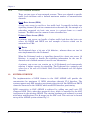
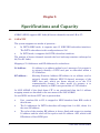
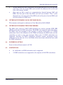
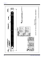
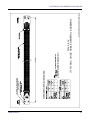
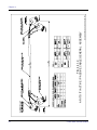
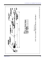
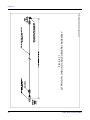
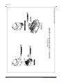
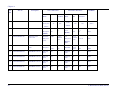
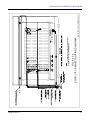
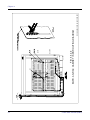
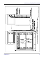
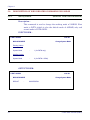
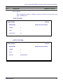
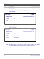
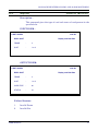
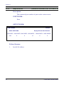
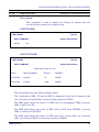
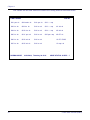
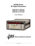
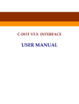
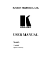
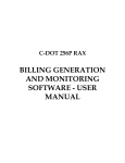
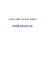
C-DOT 256P AN-RAX (ISDN)
USER MANUAL
Section No. 356-027-0918
System
Practices
Draft 01, May 2005
C-DOT 256P AN-RAX (ISDN)
USER MANUAL
© 2005, C-DOT
Printed in India
C-DOT 256P AN-RAX (ISDN)
USER MANUAL
DRAFT 01
MAY 2005
JYAISTHA 2062
SERIES 000 : OVERVIEW
CSP SECTION NO. 356-027-0918
THIS C–DOT SYSTEM PRACTICE REFERS TO THE C–DOT ACCESS NETWORK 256 PORT
RURAL AUTOMATIC EXCHANGE [ABBREVIATED AS C–DOT AN-RAX (256P) IN THE REST OF
THIS PUBLICATION].
THE INFORMATION IN THIS SYSTEM PRACTICE IS FOR INFORMATION PURPOSES AND IS
SUBJECT TO CHANGE WITHOUT NOTICE.
A COMMENT FORM HAS BEEN INCLUDED AT THE END OF THIS PUBLICATION FOR
READER'S COMMENTS. IF THE FORM HAS BEEN USED, COMMENTS MAY BE ADDRESSED
TO THE DIRECTOR (C & S), CENTRE FOR DEVELOPMENT OF TELEMATICS, C-DOT
CAMPUS, MEHRAULI, NEW DELHI - 110 030
© 2005
BY C–DOT, NEW DELHI.
Table of Contents
Chapter 1.
Chapter 2.
Chapter 3.
Chapter 4.
Chapter 5.
Introduction ..............................................................................................................................5
1.1.
The Document ................................................................................................................5
1.2.
ISDN ...............................................................................................................................5
1.3.
System Overview............................................................................................................6
Specifications and Capacity .....................................................................................................8
2.1.
Capacity ..........................................................................................................................8
2.2.
Interface Towards Local Exchange (LE).......................................................................9
2.3.
Interface Towards the Subscribers ...............................................................................9
2.4.
Powering Option.............................................................................................................9
2.5.
Limitations .....................................................................................................................9
System Architecture ...............................................................................................................10
3.1.
Compact ISDN Terminal Unit (CIT) ..........................................................................10
3.2.
Hardware Architecture ................................................................................................12
3.3.
Software Architecture ..................................................................................................12
Conversion and Retrofit Procedure .......................................................................................15
4.1.
Conversion of 256P RAX TO C-DOT 256P AN RAX (ISDN) .....................................15
4.2.
Conversin of C-DOT AN-RAX (256P) TO C-DOT 256P AN RAX (ISDN).................15
4.3.
Procedure of Conversion ..............................................................................................15
4.4.
Cables Used in AN RAX (ISDN) .................................................................................19
Man-Machine Interface (MMI) and Alarm Monitoring........................................................34
5.1.
Description of New Parameters ..................................................................................34
5.2.
Description of ISDN Related Commands for ANRAX ...............................................38
H:\HOME\ANRAX\ANRAXUSMN-ISDN.DOC
May 24, 2005
Chapter 1.
Introduction
1.1.
THE DOCUMENT
This document provides a general description of ISDN BRI interface provisioning on
256P AN RAX. The feature is explained in terms of the hardware system overview,
capacity modifications in ANRAX cards & system Engineering to support ISDN,
software architecture design, Man-machine commands & display. It also provides
information regarding the implementation of ISDN feature in the existing ANRAX
and C-DOT 256P RAX. The procedure to implement ISDN feature in C-DOT 256P
AN RAX and C-DOT 256P RAX is given in Chapter IV..
1.2.
1.2.1.
ISDN
Overview
An Integrated services Digital Network (ISDN) is a type of communication
network that transports voice, data, text and image information in digital
form between network access points.
ISDN provides digital end to end connectivity which means that terminals
and subscribers lines are digital. Digital communication offers a safer and a
more flexible transfer of information than analogue communication. ISDN
supports a wide range of services covering all the telecommunication services
today and also new services for the future.
At present there are dedicated networks for the transport of voice and
various forms of data. Subscribers needs separate accesses for different
networks and services like Videotext, Telephone, facsimile, Computer, Telex
etc. ISDN gives the subscriber combined or integrated access to these
services. The integrated access implies that an ISDN customer has access to
both voice and non-voice services through or single subscriber line. These
services, in some cases depending on terminal type, are available to the
subscriber at a single terminal.
The access has a number of time multiplexed communication channels and a
separate channel for signalling.
USER MANUAL
5
Chapter 1.
1.2.2.
User Network Accesses
There are two types of user-network accesses. These are adapted to specific
traffic load situations with a defined maximum number of communication
channels.
Basic Rate Access (BRA)
A basic rate access is used for a low traffic load. It normally includes one
signalling channel (D) and two communication channels (B). An example of a
subscriber connected via basic rate access is a private home or a small
business. The BRA uses the common 2-wire subscriber line.
Primary Rate Access (PRA)
A primary rate access can handle a higher traffic load than the basic rate
access. An ISPBX and IMUX are two example of devices which can be
connected to a PRA.
Bit Rates
The B-channels have a bit rate of 64 kbits/sec., whereas there are two bit
rates implemented for the D-channel.
When the D-channel used as a signalling channel for a basic rate access, 16
kbits/sec. is enough to handle the signalling information for the two Bchannels and a limited amount of user-to-user information.
A primary rate access can contain up to 30 B-channels and consequently
requires a higher capacity for signalling. The D-channel for a primary rate
access has a bit rate of 64 kbit/s. Both D and B-channels are full duplex
channels.
1.3.
SYSTEM OVERVIEW
The implementation of ISDN feature in the 256P ANRAX will provide the
concentration for maximum 15 ISDN subscribers through V5.2 Interface. The
system supports only BRI interface provisioning thus devices like ISPBX and IMUX
cannot be connected to the ANRAX, which needs PRI interface provisioning.
ISDN connectivity in 256P ANRAX is achieved by adding one small unit CIT
(Compact ISDN Unit), other than master & slave, which is controlled by the ARC
card present in the existing ANRAX. The existing hardware and software is reused
with minor modifications (Cut & straps) on the ARC card. This unit can be housed
on top of the ANRAX system cabinet Fig.1.1.
6
C-DOT 256P AN-RAX (ISDN)
INTRODUCTION
CIT
Frame-3
New Unit
MASTER (ARC)
Frame-1
Existing 256P
ANRAX
System Interface
Signals (Power, Voice
and Control Signals)
SLAVE (ARI)
Frame-2
Fig. 1.1
Block Diagram of ANRAX with CIT Cabinet
The product supports all three level remotting. Call processing, charging, billing,
traffic monitoring and switching are performed at LE, whereas ANRAX plays the
role of front end termination for both PSTN and ISDN subscribers at remote end.
USER MANUAL
7
Chapter 2.
Specifications and Capacity
ANRAX (ISDN) supports 2E1 links (60 bearer channels) towards LE on V5.
2.1.
CAPACITY
The system supports two modes of operation •
In PSTN+ISDN mode, it supports upto 15 ISDN BRI subscriber interfaces.
The PSTN subscribers in this configuration are 216.
•
In PSTN mode, it supports 248 PSTN subscriber interfaces.
The number of bearer channels towards the local exchange remains unchanged as
60 (Two E1 links).
Mapping of L3-Addresses and EF-Addresses for subscribers
L3 Address -
L3 address is an address within layer 3 messages. It's purpose is
to uniquely identify a PSTN user port or subscriber within a
V5.2 Interface.
EF-Address -
(Envelop Function Address) EF-address in an address used to
uniquely identify different ISDN D-channel messages of the
ISDN user port, which are frame relayed on to the V5.2
communication channel. In other words it's purpose is to
uniquely identify an ISDN user port within a V5.2 Interface.
In 256P ANRAX if the third frame CIT is not provisioned then the L3 address
mapping remain as described in the user manual for 256P ANRAX.
In case ISDN 3rd frame CCIT unit is present then,
8
•
Port numbers 224 to 255 is mapped to ISDN timeslots from BRL cards of
third frame.
•
The L3 addresses for PSTN subscriber will range from 0 to 223, where 0 is
the start LE address.
•
The value of the starting EF address is always fixed with respect to starting
L3 address and the value will be equal to start L3 address + 225, which is the
EF address of first ISDN port.
C-DOT 256P AN-RAX (ISDN)
SPECIFICATIONS AND CAPACITY
2.2.
•
The EF address for ISDN subscribers will range from 225 to 231 for first BRl
card, 240 to 247 for second BRL card and the L3 addresses 232 to 239 and
248 to 255 remain blocked.
•
Since port no. 224 is used as a communication channel between ARC and
BRLs, the first port of the first BRL card will not available. Thus 7 ports
(from port no. 2 to port no.8) of first BRL card and 8 ports of second BRL card
will be available for ISDN user.
INTERFACE TOWARDS LOCAL EXCHANGE (LE)
This remains unchanged as reference to User Manual for 256P ANRAX.
2.3.
INTERFACE TOWARDS THE SUBSCRIBERS
The BRL cards (used in C-DOT MAX products) are used to provide ISDN BRI
(2B+D) connection for ISDN subscribers. Each BRL card supports eight subscribers.
Two BRL cards are equipped in the systems, to provide connectivity to 15 ISDN
subscribers. One of the timeslots in the TDM bus between the BRL cards and the
controllers is used to carry the messages. Hence only 15 ISDN subscribers are
supported. Provision for PSTN subscribers interface remain unchanged except
subscriber on the slots nos. 21 to 24 (TG#8) of the slave frame which has been used
for ISDN subscribers.
2.4.
POWERING OPTION
Power is derived from nominal -48V DC.
2.5.
LIMITATIONS
•
In 128P mode, no ISDN subscriber can be supported.
•
15 ISDN subscribers are supported at the expense of 32 PSTN subscribers.
USER MANUAL
9
Chapter 3.
System Architecture
The major change in the system architecture is the addition of a Compact ISDN
Unit (CIT) cabinet to support ISDN BRI Interface the basic block diagrams for the
system is shown in Fig. 3.1.
256P ANRAX
..
120 PSTN
Subscribers
...
..
SLAVE
Frame
...
96 PSTN
Subscribers
CIT
Frame
2.048 Mbps Links for
V5.2 Interface
DTK0
MASTER
Frame
...
15 ISDN
Subscribers
DTK1
VDU
Single 0 230 V ±10% 50 Hz
-48V DC
Power
Plant
Fig. 3.1
Simplified System Architecture of 256P ANRAX with ISDN Unit
3.1.
COMPACT ISDN TERMINAL UNIT (CIT)
The external Compact ISDN Unit (CIT) houses one Power Unit (EPU), two ISDN
Terminal Unit Interface (ITI cards and two BRL cards. The Cabinet has 13
available slots for the future enhancement in capacity. The BRL cards are
interfaced to the main controller, i.e., ARC card, through ITI cards whose functions
10
C-DOT 256P AN-RAX (ISDN)
SYSTEM ARCHITECTURE
are similar to the ARI cards in the slave frame of ANRAX. The ITI cards are defined
by making minor modifications on the ARI cards.
A 2 Mbps digital link of TG#8 (Terminal Group) of the slave frame is used for the
communication between ARC and BRL cards.
The onward TG Link#8 and the control signals (clock, sync) are extended to the ITI
cards from ARC. The return TG Link#8 from the ITI cards reaches ARC card. The
first PCM time slot of the above link carry messages between BRL cards and ARC
card for supporting ISDN protocol oner V5.2 Interface as shown in Fig. 3.2.
7
2B+D
Subscribers
Channel 3-16
(Bearers from all BR1 Lines)
BRL 1
BRI Interfaces
Signalling
Information
8
Subscribers
2B+D
BRI Interfaces
ITI Card
(Modified
ARI Card)
BRL 2
TG#8 30
ISDN
Bearer
Channels+1
Message
Channel
Channel 17-32
(Bearers from all BR1 Lines)
Compact ISDN Unit
PCM1
Other TGs for PSTN Interfaces
ARC
V5.2 Interface
towards LE
PCM2
Fig. 3.2
USER MANUAL
11
Chapter 3.
3.2.
HARDWARE ARCHITECTURE
There is no major charge in the H/W Architecture of the ARC and ARI cards.
3.2.1.
Configuration
Apart from existing AN-RAX the distribution of cards for compact ISDN unit
is as follows -
3.2.2.
ISDN Terminal Unit Interface (ITI) card
= 2 nos.
Basic Rate Line (BRL) cards
= 2 nos.
Power Supply cards
= 1 no.
ANRAX Controller Card
The minor changes on the existing ARC S01 card are two cut and three
straps.
These changes are required to use the SCC3 of the Master IMP of the ARC
card for both MMI and debug purpose. Previously Master IMP was used only
for MMI commands and slave IMP was used for debug purpose.
The SCC3 of the slave IMP is used for handling BRL card messages.
3.2.3.
Basic Rate Line Card (BRL)
BRL cards in the CIT cabinet of ANRAX are already working in the C-DOT
MAX, can be used by removing or modifying some portions which are not
required for ANRAX.
Both BRL cards communicate to the ARC card with a 2 Mbps. PCM link
through ITI card. The ISDN subscriber interfaces are directly tapped from
the back panel of BRL cards.
3.2.4.
ITI Cards
ITI is a modified version of AR1. Its functions and architecture is same as for
ARI card.
3.3.
SOFTWARE ARCHITECTURE
There is no major change in software architecture of the existing ANRAX. And the
approach was to reuse the all existing software of ANRAX.
Modified Software Entities for ISDN on ANRAX are as follows -
12
C-DOT 256P AN-RAX (ISDN)
SYSTEM ARCHITECTURE
3.3.1.
V5 Modules
3.3.1.1.
Enhanced Control Protocol (CP)
The CP protocol module has been enhanced to take care of the BRL port
activation and deactivation procedures. Now this process supports the
following message :
3.3.1.2.
a)
FE 101 (activate access)
b)
FE 102(activation initiated by user)
c)
FE 104 (access activated)
d)
FE 105 (deactivate access)
e)
FE 106 (access deactivated)
f)
FE 207 (D-Channel block)
g)
FE 208 (D-Channel unblock)
Enhanced BCC
The BCC protocol module can now support the ISDN channel identification
(2B) and multi slot connections.
3.3.2.
An Modules
3.3.2.1.
Maintenance Software (FST)
The software now monitors the links towards the BRL cards also. This entity
informs OAT to update the Alarm panel for BRL card status. It blocks and
unblocks the ISDN ports upon jack-out and jack-in of the BRL cards.
3.3.2.2.
Non-Machine Interface (OAT)
Now commands have been added to OAT to equip the BRL cards. The port
related commands have been extended to ISDN ports.
3.3.2.3.
IPCP Layers
The IPCP now handles two separate two separate data links for the two BRL
cards for the transfer of maintenance messages and the port activation and
deactivation interface.
3.3.2.4.
Frame Relay Functionality in IPCP Layers
The D-channel messages are frame relayed to LE on the Active Link by IPCP
layers after performing some required basic checks.
USER MANUAL
13
Chapter 3.
3.3.2.5.
Data Base Task (DBT)
The ANRAX database is enhanced to handle 2 new types of units BRL and
ITI.
3.3.3.
BRL Card Software
This software is built in the lines of the ISTU BRL software. The software
has the following processes.
3.3.3.1.
Basic Rate Physical Handler (BRPH)
This process handles the activation and de-activation of the ISDN ports and
also any error indication from the ISDN ports.
3.3.3.2.
Basic Rate Rx Handler (BRRx)
Basic Rate Rx Handler (BRTx)
These processes act as the driver processes for receiving and sending
D-channel messages to the ISDN equipment from the BRL card.
3.3.3.3.
Layer 1 Frame Handler (L1FH)
This process acts as the gatekeeper for allowing flow of signalling messages
towards ARC from BRL card. It interfaces with Control Protocol of ARC to
control the ISDN ports.
3.3.3.4.
IPCP Process for Communication to ARC Card (SCCT, DLCT, DLPT)
These are used to maintain the LAPD link between the ARC and BRL cards
for transfer of Maintenance messages and the D-channel messages.
14
C-DOT 256P AN-RAX (ISDN)
Chapter 4.
Conversion and Retrofit Procedure
4.1.
CONVERSION OF 256P RAX TO C-DOT 256P AN RAX (ISDN)
In order to convert C-DOT 256P RAX into C-DOT 256P AN RAX (ISDN), first 256P
RAX is to be converted to 256P AN RAX. The broad guidelines for conversion of
256P RAX to 256P AN RAX are as under
•
Switch off C-DOT 256P RAX.
•
Cards which are not required in C-DOT 256P AN RAX are to be removed.
•
The Cable which are not required in C-DOT 256P AN RAX are to be removed.
•
The motherboard is to be modified by putting straps as required for the
conversion from 256P RAX to 256P AN RAX.
•
Pre-charge pins are to be placed in slots where ARC and ARI are to be put.
•
New cards & cables which are required in AN RAX are to be put in the
system.
Note: Please refer to Chapter 6 of USER MANUAL of C-DOT AN-RAX (256P) for
details of above guidelines.
To make it AN RAX (ISDN), follow the guidelines as given below.
4.2.
CONVERSIN OF C-DOT AN-RAX (256P) TO C-DOT 256P AN RAX (ISDN)
ISDN implementation on C-DOT AN-RAX (256P) require -
4.3.
1.
Equipped compact ISDN TU
2.
Existing AN-RAX system having relevant software.
3.
Cables as given is section 4.4.
4.
The 250 mA slow flow fuse (FH3) at MP power point in PDP will be changed
to 6.3A slow blow.
PROCEDURE OF CONVERSION
1.
Switch off the power supply of 256P RAX/256 P AN RAX.
USER MANUAL
15
Chapter 4.
2.
Take out ARC cards and make two cuts and three straps
Details of Cut & straps on ARC are -
16
Cut C1
→ cut trace fro U38/7 to K6/4 on solder side
Cut C2
→ cut trace from Ba20 to RN43/5 on solder side
Strap S1
→ strap Ba28 to K6/4
Strap S2
→ strap K6/9 to Bc28
Strap S3
→ strap RN43/5 to RN43/10
3.
Put relevant PROMs on U20 & U60 location of ARC and put back ARC's and
front flat cable.(Refer section 4.3.1 for checksum)
4.
Remove Interframe cables IFC0, IFC1, IFC2, IFC3. Use cables as given in
Table 4.4.1 place them as give in Table 4.4.2.
5.
Change 250 mA slow blow fuse (FH3) at Mp power point on PDP on AN-RAX
to 6.3 A slow blow.
6.
Insert cards in AN-RAX and CIT as given in H/W configuration of AN-RAX
(ISDN), section 4.3.2.
7.
Switch on AN-RAX and CIT power supply. C-DOT logo shall appear on Dumb
terminal.
8.
Give password and make both the DTK OOS by giving frc-dtk-OOS
command.
9.
Note down the AI characteristics by giving command displ-ai-char.
10.
Give init-sys command and boot using default data by giving Boot level as 2.
11.
Delete ai by giving command del-ai.
12.
Create AN interface by giving cre-ai command. Parameters in cre-ai should
match with the parameters defined at LE.
13.
Select PSTN only or PSTN+ISDN mode by giving command mode-sys-mode.
14.
Unequip LCC cards from slot-No 21, 22, 23, 24 of frame 2 (slave) if PSTN +
ISDN mode is selected.
15.
Equip slot No. 1 & 2 of frame 3 for Brl using equip-slot command.
16.
Make DTK in service by using put-dtk-ins command.
17.
Give start-ai command to bring up the interface.
C-DOT 256P AN-RAX (ISDN)
CONVERSION AND RETROFIT PROCEDURE
4.3.1.
H/W and S/W Status of C-DOT 256 Port AN-RAX (ISDN)
The hardware and software status of C-DOT 256 port AN-RAX (ISDN) is as
under.
Hardware Status of C-DOT 256 Port AN-RAX (ISDN)
Master Frame
Sl.No.
Card Name
Part Code
Card Description
1.
ARC
APC-ARCA62/O-S01
AN-RAX controller card
2.
SPC/ISP
APC-SPC001/T-S06
APC-ISP867/T-S02
APC-ISP867/T-S03
Signalling processor card/Integrated
Signalling
Processor Card
3.
LCC
APC-LCC037/T-S08
Line Circuit Card
4.
CCM
APC-CCM241/T-A00
Coin Collection Box with 16KHz
Metering Card
5.
RTC
APC-RTC327/T-S02
RAX Terminal Tester Card
6.
PSU
APC-PSU036/T-A09
Power Supply Card
Slave Frame
Sl.No.
Card Name
Part Code
Card Description
1.
ARI
APC-ARIE11/T-S00
AN-RAX Interface card
2.
SPC/ISP
APC-SPC001/T-S06
APC-ISP867/T-S02
APC-ISP867/T-S03
Signalling processor card/Integrated
Signalling
Processor Card
3.
LCC
APC-LCC037/T-S08
Line Circuit Card
4.
CCM
APC-CCM241/T-A00
Coin Collection Box with 16KHz
Metering Card
5.
PSU
APC-PSU036/T-A09
Power Supply Card
Compact ISDN TU (CIT)
Sl.No.
Card Name
Part Code
Card Description
1.
BRL
APC-BRL537/H-A01
Basic Rate Line Card
2.
ITI
APC-ARIE11/T-A00
AN-RAX Interface Card (ITI)
3.
PSU
APC-PSU036/T-A09
Power Supply Card
USER MANUAL
17
Chapter 4.
Software Status of C-DOT 256 Port AN-RAX (ISDN)
Sl.No.
4.3.2.
Card Name
Part Code
EPROM
Type
ARC
APC-ARCA62/O-S01
27c801
27c801
U20 (H)
U2 (L)
E0A6
5EFC
2.
BRL
APC-BRL537/H-A01
27c040
27c040
U50
U60
0245
3873
3.
RTC
APC-RTC327/T-S02
27c256
U5
A8DE
H/W Configurations AN-RAX (ISDN)
I
T
B
R
L
B
R
L
A
0
A
0
1
1
L S
A U
Checksum
1.
C
S P
Position
L L
C
C C
C
L
C
C
L
C
L
C
C
L
C
C
L
C
C
L
C
C
C
V 0
S
A
A
P
R
R
C
I
I
0
0
1
S
A
P
A
R
C
C
0
C
I I
T T
I I
1
0
P
S
U
1
S
P
C
1
L
S
P
C
1
L
C
L
C
C
L
C
C
L
C
C
C
U
N
U
S
E
D
U
N
U
S
E
D
U
N
U
S
E
D
U
N
U
S
E
D
P
S
U
1
E
M P
A S
S U
T 0
L L
C
C C
C
L
C
C
L
C
C
L
C
C
R
T
C
L
C
C
L
C
C
0
R
C
C
L
C
C
L
C
C
L
C
C
L L L
C C C
C C C
L P
C S
C U
1
1
E
R
The above Setup shows CIT cabinet placed over the AN-RAX system. ITI
(ARI-A00) card acts as an extension of ARC card in the ISDN frame.
Voice/Data signal and the signaling information are exchanged between ITI
card and the ARC card through the Interframe PCM cables extended to CIT
frame.
18
C-DOT 256P AN-RAX (ISDN)
CONVERSION AND RETROFIT PROCEDURE
Changes required in the existing AN- RAX system to support ISDN on ANRAX
I.
#
II.
Card
Qty
Remarks
Line Connecting Card (LCC)
4
Slot No 21 to 24 should be
empty in slave frame. ITI card
& BRL card in CIT frame will
use the PCM link of these four
LCCs.
Cards to be added
#
Card
Qty
1.
ISDN TU Interface card (ARI-A00) or ITI
2
ARI-A00 card will occupy slots
9 & 10 of CIT frame
2.
Basic Rate Interface Line card (BRL-A01)
2*
BRL-A01 card will occupy slots
1 & 2 of Slave frame
3.
Power Supply Card (PSU-A09)
1
PSU-A09 card will occupy slot
12 of CIT frame
* Note:
4.4.
Cards to be removed
Remarks
BRL card quantity depends on the number of BRI subscribers needed.
Max 2 BRL can be used.
CABLES USED IN AN RAX (ISDN)
4.4.1.
Cables used in C-DOT 256P AN RAX (ISDN) are given in Table 4.4.1.
4.4.2.
Cable Placement in given in Table 4.4.2
Routing of the cable in shown in Figure 3.3.2a, 4.4.2b and 4.4.2.c.
Table 4.4.1
SL.
NO
Cable type
Qty
Remarks
Marker
Fig.
1.
ARC to ITI voice cable
2
Extend PCM out of ARC
to PCM in of ARI and
ITI
ACIT0/
ACIT1
4.4.1.a
2.
ARI to CIT voice cable
2
Extend PCM out of ARI
to CIT for muxing
AICI0
AICI1
4.4.1.b
3.
ARI to ITI Active/Passive
cable
1
Extend Active/Passive
signal of ARI to
AIITX
4.4.1c
4.
ITI to ARC voice cable
2
Extend ITI PCM
out/ARI PCM out to
ARC
ITAC0
ITAC1
4.4.1d
5.
RAX PDP to CIT power
bl
1
Extend 48V & 48VGND
f
RAX PDP CIT
PD.1X0
4.4.1e
USER MANUAL
19
Chapter 4.
cable
20
from RAX PDP to CIT
6.
CIT Protection ground
cable
1
7.
PSTN MUX Connector
3
8.
ISDN MUX Connector
Extend CIT Protection
ground cable to
Exchange Earth bar
ABEB
4.4.1f
PSTN
4.4.1g
ISDN
4.4.1h
C-DOT 256P AN-RAX (ISDN)
USER MANUAL
\DESIGN\ANRAXISDN-UM\ANRXISDN-VC
FIG. 4.4.1.a
ARC TO ITI VOICE CABLE GENERAL ASSEMBLY
CONVERSION AND RETROFIT PROCEDURE
21
22
\DESIGN\ANRAXISDN-UM\ANRXISDN-VC1
FIG. 4.4.1.b
ARI TO CIT VOICE CABLE GENERAL ASSEMBLY
Chapter 4.
C-DOT 256P AN-RAX (ISDN)
USER MANUAL
\DESIGN\ANRAXISDN-UM\ANRXISDN-VC2
FIG. 4.4.1.c
ITI TO ARC VOICE CABLE GENERAL ASSEMBLY
CONVERSION AND RETROFIT PROCEDURE
23
24
\DESIGN\ANRAXISDN-UM\ANRXISDN-APC
FIG. 4.4.1.d
ARI TO ITI ACTIVE / PASSIVE CABLE GENERAL ASSEMBLY
Chapter 4.
C-DOT 256P AN-RAX (ISDN)
USER MANUAL
\DESIGN\ANRAXISDN-UM\ANRXISDN-PCC
FIG. 4.4.1.e
PDP TO IXC CARD CABLE GENERAL ASSEMBLY
CONVERSION AND RETROFIT PROCEDURE
25
26
\DESIGN\ANRAXISDN-UM\ANRXISDN-CPC
FIG. 4.4.1.f
CIT PRODTN. GROUND CABLE GENERAL ASSEMBLY
Chapter 4.
C-DOT 256P AN-RAX (ISDN)
USER MANUAL
\DESIGN\ANRAXISDN-UM\ANRXISDN-PMC1
FIG. 4.4.1.g
PSTN MUX CABLE GENERAL ASSEMBLY
CONVERSION AND RETROFIT PROCEDURE
27
FIG. 4.4.1.h
ISDN MUX CABLE GENERAL ASSEMBLY
\DESIGN\ANRAXISDN-UM\ANRXISDN-PMC
Chapter 4.
28
C-DOT 256P AN-RAX (ISDN)
CONVERSION AND RETROFIT PROCEDURE
Table 4.4.2
SL
Part No
Description
Source Placement
Destination Placement
MARKER
NO
1.
ACB-IANACITX-000
ARC to ITI voice cable
Back
Plane
Slot NO
7X2
Location
Back
Plane
Slot
NO
7X2
Location
Master
Frame
12A
1st
Slave frame
12A
1st
(MOD2)
(MOD1)
ACIT0
CIT
Back plane
9A
1st
15A
1st
(MOD3)
2.
ACB-IANACITX-000
Master
Frame
15A
1
st
Slave frame
(MOD2)
(MOD1)
ACIT1
CIT
Back plane
10A
1st
J5
1st
(MOD3)
3.
ACB-IANAICIX-000
Slave
Frame
ARI to CIT voice cable
4.
ACB-IANAICIX-000
12A
2nd
Back plane
(MOD1)
Slave
Frame
ACB-IANAIITX-000
ARI to ITI Status cable
Slave
Frame
15A
2nd
(MOD3)
USER MANUAL
CIT
J5
3rd
J6
3rd
AICI1
Back plane
(MOD2)
12A
3rd
CIT
Back plane
(MOD1)
Slave
Frame
AICI0
(MOD2)
(MOD1)
5.
CIT
(MOD2)
15A
3rd
CIT
AIITX
J6
4th
A11T0
Back plane
(MOD4)
29
Chapter 4.
SL
Part No
Description
Source Placement
Destination Placement
MARKER
NO
Back
Plane
6.
ACB-IANITACX-000
ITI to ARC voice cable
Slot NO
7X2
Location
CIT
Back plane
J5
2nd
ACB-IANITACX-000
ITI to ARC voice cable
CIT
Back plane
J5
4th
9.
ACB-IANPDIX0-000
ACB-IANABEB0-000
RAX PDP to CIT
Power cable
RAX PDP
PDP
(MP power
point)
CIT Protection Ground
Cable
CIT
backplane
7X2
Location
12A
2nd
ITAC0
Master
frame
15A
2nd
ITAC1
4 pin
relimate
conn
-48V in
PDIX
EARTH
BUS BAR
M6
screw
point
NA
ABEB
(MOD2)
(MOD1)
8.
Master
frame
Slot
NO
(MOD2)
(MOD1)
7.
Back
Plane
J1 (4 P
relimate
conn)
CIT
Back plane
IXC face
plate
FT2
NA
10.
ACB-CITPSTNX-000
PSTN MUX connector
CIT back
plane
J3
1st
CIT back
plane
J3
1st
PSTN
11.
ACB-CITPSTNX-000
PSTN MUX connector
CIT back
plane
J3
2nd
CIT back
plane
J3
2nd
PSTN
12.
ACB-CITPSTNX-000
PSTN MUX connector
CIT back
plane
J3
3rd
CIT back
plane
J3
3rd
PSTN
13.
ACB-CITISDNX-000
ISDN MUX connector
CIT back
plane
J3
4th
CIT back
plane
J3
4th
ISDN
30
C-DOT 256P AN-RAX (ISDN)
FIG. 4.4.2.a
EQPD. CIT CABINET ROUTING DIAGRAM
\DESIGN\ANRAXISDN-UM\ANRXISDN-ECC
CONVERSION AND RETROFIT PROCEDURE
USER MANUAL
31
32
\DESIGN\ANRAXISDN-UM\ANRXISDN-ERC
FIG. 4.4.2.b
EQPD. AN-RAX CABINET ISDN ROUTING DIAGRAM
MASTER
SLAVE
Chapter 4.
C-DOT 256P AN-RAX (ISDN)
USER MANUAL
\DESIGN\ANRAXISDN-UM\ANRXISDN-IAS
FIG. 4.4.2.c
ISDN ON AN-RAX SYSTEM GENERAL ASSEMBLY
CONVERSION AND RETROFIT PROCEDURE
33
Chapter 5.
Man-Machine Interface (MMI) and
Alarm Monitoring
5.1.
DESCRIPTION OF NEW PARAMETERS
This section contains the details of parameters that are need for the administration
of ISDN subscribers (also valid for PSTN mode) at ANRAX.
5.1.1.
CARD TYPE
PARAMETER NAME
: Type of Card
MNEMONIC
: CARD TYPE
DEFINITION
: It defines the Hardware Type of Termination
cards actually placed in the slot.
TYPE
: Alphanumeric
POSSIBLE VALUES
: lcc - Line Circuit Card
ccb - Coin Collection Box line card
rtc - RAX Terminal tester Card
brl - Basic Rate Line card
34
DEFAULT
: LCC
REMARKS
: rtc can be equipped only in slot 8 of master
frame brl can equip only in ISDN+PSTN mode.
C-DOT 256P AN-RAX (ISDN)
MAN-MACHINE INTERFACE (MMI) AND ALARM MONITORING
5.1.2.
5.1.3.
EF ADDRESS
PARAMETER NAME
: Envelop function Address
MNEMONIC
: EF ADDRESS
DEFINITION
: It defines the ISDN User Port.
TYPE
: Numeric
POSSIBLE VALUES
: STL3+224 TO STL3+231 and STL3+240 to
STL3+247 STL3 = START LE Address
DEFAULT
: Start EF Address = Start L3 addr + 224
REMARKS
:
FRAME
PARAMETER NAME
: Frame Number
MNEMONIC
: FRAME
DEFINITION
: It defines the Frame Number.
TYPE
: Numeric
POSSIBLE VALUES
: 1 - for Master Frame
2 - for Slave Frame
3 - ISDN Unit
DEFAULT
:
REMARKS
:
USER MANUAL
35
Chapter 5.
5.1.4.
5.1.5.
36
SLOT
PARAMETER NAME
: Card Slot Numbers
MNEMONIC
: SLOT
DEFINITION
: It defines the physical slot of terminal card.
TYPE
: Numeric
POSSIBLE VALUES
: 03 to 10, 17 to 24 for Master & Slave 01 to 02
for ISDN Unit
DEFAULT
: In default ISDN slot are not equipped.
REMARKS
:
STARTING EF ADDRESS
PARAMETER NAME
: Starting EF Address
MNEMONIC
: STARTING EF ADDR
DEFINITION
: Identifies the start EF address and starts from
start EF Address +224
TYPE
: Numeric
POSSIBLE VALUES
: Start L3 Addr + 224
DEFAULT
: None
REMARKS
:
C-DOT 256P AN-RAX (ISDN)
MAN-MACHINE INTERFACE (MMI) AND ALARM MONITORING
5.1.6.
SYSTEM MODE
PARAMETER NAME
: System Mode
MNEMONIC
: SYSTEM MODE
DEFINITION
: To change the working mode of ANRAX
TYPE
: Numeric
POSSIBLE VALUES
: 1 for PSTN only
2 for ISDN + PSTN
5.1.7.
DEFAULT
: 1
REMARKS
:
UNIT ID
PARAMETER NAME
: Unit Identification
MNEMONIC
: UNIT ID
DEFINITION
: Identification of the unit for which alarm is to
be displayed.
TYPE
: Alphanumeric
POSSIBLE VALUES
: Additional possible values are
brl_1
brl_2
ITI1 - ISDN Terminal Interface card
ITI2 -
DEFAULT
: None
REMARKS
:
USER MANUAL
37
Chapter 5.
5.2.
5.2.1.
DESCRIPTION OF ISDN RELATED COMMANDS FOR ANRAX
mod-sys-mode
(MODIFY THE SYSTEM MODE)
Description :
This command is used to change the working mode of ANRAX. First
mode is PSTN (which is also the default mode of ANRAX) only and
second mode is PSTN+ISDN.
INPUT FORM :
C-DOT ANRAX
<site-id>
MOD-SYS-MODE
Change System Mode
Existing Values :
System Mode
:
1 (for PSTN only)
:
2 (for PSTN + ISDN)
Modified Values
System Mode
OUTPUT FORM :
C-DOT ANRAX
<site-id>
MOD-SYS-MODE
RESULT
38
:
Change System Mode
SUCCESSFUL
C-DOT 256P AN-RAX (ISDN)
MAN-MACHINE INTERFACE (MMI) AND ALARM MONITORING
5.2.2.
equip-slot
(EQUIP A SLOT)
Description :
This command is used to configure a physical slot for a particular card
type in ISDN unit.
INPUT FORM :
C-DOT ANRAX
<site-id>
EQUIP-SLOT
Equip the card in the Slot
FRAME
:
3
SLOT
:
1
CARD TYPE
:
brl
OUTPUT FORM :
C-DOT ANRAX
<site-id>
EQUIP-SLOT
Equip the card in the Slot
FRAME
:
3
SLOT
:
1
RESULT
:
SUCCESSFUL
USER MANUAL
39
Chapter 5.
5.2.3.
unequip-slot
(UNEQUIP A SLOT)
Description :
This command is used to unequip a physical slot.
INPUT FORM :
C-DOT ANRAX
<site-id>
UNEQUIP-SLOT
Unequip the card from the Slot
FRAME
:
3
SLOT
:
1
OUTPUT FORM :
C-DOT ANRAX
<site-id>
UNEQUIP-SLOT
Unequip the card from the Slot
FRAME
:
3
SLOT
:
1
RESULT
:
SUCCESSFUL
Note : The Result may be fail due to reasons "SLOT IS NOT EQUIPPED",
"INVALID FRAME" OR "INVALID SLOT or "PORTS ARE INS".
40
C-DOT 256P AN-RAX (ISDN)
MAN-MACHINE INTERFACE (MMI) AND ALARM MONITORING
5.2.4.
displ-slot
(DISPLAY THE SLOT)
Description :
This command gives the type of card and status of card present in the
specified slot.
INPUT FORM :
C-DOT ANRAX
<site-id>
DISPL-SLOT
Display card Slot Data
FRAME
:
3
SLOT
:
1 or 2
OUTPUT FORM :
C-DOT ANRAX
<site-id>
DISPL-SLOT
Display card Slot Data
FRAME
:
3
SLOT
:
1 or 2
CARD TYPE
:
brl
STATUS
:
IS
Failure Reasons :
1.
Invalid Frame
2.
Invalid Slot
USER MANUAL
41
Chapter 5.
5.2.5.
displ-ai-char
(DISPLAY AI CHARACTERISTICS)
Description :
This command can be used to display the AN interface characteristics.
INPUT FORM :
None
OUTPUT FORM :
C-DOT ANRAX
<site-id>
DISPL-AI-CHAR
42
Display An Interface Characteristics
V5 Interface ID
:
1
V5 Interface Name
:
ANRAX
Variant ID
:
1
Stating L3 Addr
:
1
Stating EF Addr
:
225
Link Configuration
:
0-0 & 1-1
Primary Link
:
0
Secondary Link
:
1
C-DOT 256P AN-RAX (ISDN)
MAN-MACHINE INTERFACE (MMI) AND ALARM MONITORING
5.2.6.
frc-trm-oos
(FORCE TERMINAL OUT OF SERVICE)
Description :
This command will be used to put AN interface subscribers out of
service forcefully.
INPUT FORM :
C-DOT ANRAX
<site-id>
FRC-TRM-OOS
L3 Address
Force Terminal Out of Service
:
Start L3 Addr + 224 (For ISDN subscriber)
Note*
Note : Range of L3 Address can be given.
OUTPUT FORM :
C-DOT ANRAX
<site-id>
FRC-TRM-OOS
Force Terminal Out of Service
L3 Address
:
Response
:
Success/Failure
Failure Reasons :
1.
Invalid L3 address
2.
Port is unequipped
3.
Port is already out of service.
USER MANUAL
43
Chapter 5.
5.2.7.
put-trm-oos
(PUT TERMINAL OUT OF SERVICE)
Description :
This command is used to put AN subscribers out of service.
INPUT FORM :
C-DOT ANRAX
<site-id>
PUT-TRM-OOS
L3 Address
Put Terminal Out of Service
:
Start L3 Addr + 224 (For ISDN subscriber)
Note*
Note : Range of L3 Address can be given.
OUTPUT FORM :
C-DOT ANRAX
<site-id>
PUT-TRM-OOS
Put Terminal Out of Service
L3 Address
:
Response
:
Success/Failure
Failure Reasons :
44
1.
Invalid L3 address
2.
Port is busy
3.
Port is unequipped
4.
Interface is down.
5.
Command execution timed out.
C-DOT 256P AN-RAX (ISDN)
MAN-MACHINE INTERFACE (MMI) AND ALARM MONITORING
5.2.8.
frc-trm-ins
(FORCE TERMINAL IN SERVICE)
Description :
This command is used for bringing the terminals in-service without
testing them.
INPUT FORM :
C-DOT ANRAX
<site-id>
FRC-TRM-INS
L3 Address
Force Terminal In Service
:
Start L3 Addr + 224 (For ISDN subscribers)
OUTPUT FORM :
C-DOT ANRAX
<site-id>
FRC-TRM-INS
Force Terminal In Service
L3 Address
:
Response
:
Success/Failure
Failure Reasons :
1.
Invalid L3 address
2.
Port is unequipped
3.
Interface down
4.
No Response form LE.
USER MANUAL
45
Chapter 5.
5.2.9.
put-trm-ins
(PUT TERMINAL IN SERVICE)
Description :
This command is used to put AN subscribers in service, after testing
the port.
INPUT FORM :
C-DOT ANRAX
<site-id>
PUT-TRM-INS
L3 Address
Put Terminal In Service
:
Start L3 Addr + 224 (For ISDN subscribers)
OUTPUT FORM :
C-DOT ANRAX
<site-id>
PUT-TRM-INS
Put Terminal In Service
L3 Address
:
Response
:
Success/Failure
Failure Reasons :
46
1.
Invalid L3 address
2.
Port is unequipped
3.
Interface down
4.
Exchange side test failed
5.
Time out no Response form LE.
C-DOT 256P AN-RAX (ISDN)
MAN-MACHINE INTERFACE (MMI) AND ALARM MONITORING
5.2.10.
displ-trm-status
(DISPLAY TERMINAL STATUS)
Description :
This command will display the port status for on AN Interface.
INPUT FORM :
C-DOT ANRAX
<site-id>
DISPL-TRM-STATUS
L3 Address
:
Display Terminal Status
Start L3 Addr + 224 (For ISDN subscribers)
OUTPUT FORM :
C-DOT ANRAX
<site-id>
DISPL-TRM-STATUS
L3 Address
Display Terminal Status
Status
1
IS
2
IS
.
.
.
.
.
.
Failure Reasons :
1.
Invalid L3 address
USER MANUAL
47
Chapter 5.
5.2.11.
displ-aicnt-oos
(DISPLAY AI PORTS OUT OF SERVICE)
Description :
This command gives number of ports under various status.
INPUT FORM :
None.
OUTPUT FORM :
C-DOT ANRAX
<site-id>
DISPL-AICNT-OOS
INS PORTS
224
Display AI Ports Out Of Service
OOS PORTS BLK PORTS UEQ PORTS
8
0
16
FOOS PORTS
8
MTCE PORTS
0
Failure Reasons :
1.
48
Invalid L3 address
C-DOT 256P AN-RAX (ISDN)
MAN-MACHINE INTERFACE (MMI) AND ALARM MONITORING
5.2.12.
displ-alrm-hist
(DISPLAY ALARM HISTORY)
Description :
This command is used to display the history of alarms that are
occurred in the system over a span of time.
INPUT FORM :
C-DOT ANRAX
<site-id>
DISPL-ALRM-HIST
Unit ID
:
Display Alarm History
brl1
OUTPUT FORM :
C-DOT ANRAX
<site-id>
DISPL-ALRM-HIST
Display Alarm History
Alarm History of the Unit : brl1
DATE
TIME OCCURRED
STATUS
SEVERITY
01/01/2004
19:54:58
IS
MAJOR
01/01/2004
19:52:00
OOS
MAJOR
The status Indication and Alarms Display Panel.
The card health of BRL, ITI and the EPU is displayed in the last 2 columns in the
last 2 columns in the2nd frame of status display panel of ANRAX.
The MMI panel shows the stauts of 2 BRL cards as unequipped (UEQ), in-service
(OK) or jaked out (JO).
The MMI panel shows the status of EPU card as PSU error PSUER), in-service
(OK) or battery low (BATLO).
The MMI panel shows the status of 2ITI cards as in service (OK), out of service
(OK), out of service (FAIL) or forced out of service (FOOS).
USER MANUAL
49
Chapter 5.
The alarms for the new units are flashed as is being done for the other units.
C-DOT ANRAX
S01 psu ok
S08 rteloc ok
S16 spc ok
S22 --- ueq
S03 lcc ok
S09 lcc ok
S16 lcc ok
S23 --- ueq
I01 brl ok
S04 lcc ok
S010 lcc ok
S16 lcc ok
S24 --- ueq
I02 brl ok
S05 lcc ok
S011 spc ok
S16 lcc ok
S25 psu ueq
I09 ITI ok
S06 lcc ok
S012 ari ok
S16 lcc ok
I10 ITI FOOS
S07 lcc ok
S015 ari ok
S16 lcc ok
I13 epu ok
NORMAL MODE
50
<site-id>
01/01/2004, Thursday 09:35:41
MORE STATUS : # HELP : ?
C-DOT 256P AN-RAX (ISDN)