1
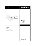
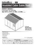
System Status:
Float Charging
RC7
RC7GS
Installation and Operator’s Manual
Xantrex
RV Series
Remote Controls
RC7 & RC7GS Remote Controls
Notice of Copyright
Xantrex RC7 and RC7GS Remote Controls Installation and
Operator’s Manual © October 2002 Xantrex International. All rights
reserved.
Xantrex is a registered trademark of Xantrex International.
Disclaimer
UNLESS SPECIFICALLY AGREED TO IN WRITING, XANTREX
TECHNOLOGY INC. (“XANTREX”)
(a) MAKES NO WARRANTY AS TO THE ACCURACY, SUFFICIENCY OR SUITABILITY OF ANY TECHNICAL OR OTHER
INFORMATION PROVIDED IN ITS MANUALS OR OTHER DOCUMENTATION.
(b) ASSUMES NO RESPONSIBILITY OR LIABILITY FOR LOSS
OR DAMAGE, WHETHER DIRECT, INDIRECT, CONSEQUENTIAL
OR INCIDENTAL, WHICH MIGHT ARISE OUT OF THE USE OF
SUCH INFORMATION. THE USE OF ANY SUCH INFORMATION
WILL BE ENTIRELY AT THE USER’S RISK.
Date and Revision
October 2002, Revision 1
Part Number
975-0050-01-01
Contact Information
Web: www.xantrex.com
Email: [email protected]
Phone: 1 800 670 0707 (toll free) 1 604 422 2777 (direct)
Fax: 1 604 420 2145
RC7 & RC7GS Remote Controls
RC7 & RC7GS Remote Controls
Table of Contents
Section
Description
Page
1.
Introduction ............................................................... 1
Features ............................................................. 1
ON/OFF Control
Meters
Controls
Status Monitoring
2.
Installation ................................................................. 3
3.
Operation ................................................................... 5
Front Panel ............................................................. 5
Indicators and Controls
Status LEDs
Inverter LED
Charge LED
Batt. Full LED
Error LED
LCD Display
Push-buttons
On/Off
Setup/Menu Item Push-button
Meter Mode Push-button
Settings Push-button
RC7 and RC7GS Setup Menu .............................. 9
Sense Search
Auto LBCO
Battery Capacity
Battery Type
Charge Rate
Set Shore Power
RC7 Setup
LCD Contrast
External Shunt
Fuelgauge Cutout
i
RC7 & RC7GS Remote Controls
3.
Operation (continued)
RC7GS Setup Menu .............................................. 14
Set Clock (RC7GS Only)
Select Genset
Generator Start
Generator Stop
Begin Gen Quiet and End Gen Quiet
Saving your Setup Choices ................................. 18
RC7 and RC7GS System Status Displays .......... 19
AC Source Messages ................................... 19
Waiting for AC
Genset Status:
Pending, Cranking and Genstart
Starter Cooldown and Gen Start
Gen Set Error Messages .............................. 20
Gen Won’t Start
Gen Quiet Fault
Low AC Input V
Inverter Mode Messages .................................. 20
Charger Mode Messages ................................. 23
Bulk Charging
Absorption Charging
Float Charging
Equalizing Charging
Inverter/Charger Error Messages .................... 25
Over Temperature
Overload
High Battery Voltage
Low Battery Voltage
DCLD Lockout Error
Charger Fault
Meters Display ....................................................... 28
Average Shunt Amps
Battery Voltage
Inverter/Charger Current
AC Output Voltage
AC Input Amps
Battery Temperature
Transformer Temperature
FET Temperature
Estimated Battery Capacity
ii
RC7 & RC7GS Remote Controls
3.
Operation (continued)
System Status Messages ..................................... 31
Battery State of Charge
Time Left to Run
Time Left to Charge
Set Shore Power
Generator Start/Stop
Generator Connection .......................................... 33
Onan Quiet Diesel
Power Tech Wiring Diagrams (2 and 3-wire)
Power Tech 2-wire
Power Tech 3-wire
RC7 and RC7GS Setup Menu .............................. 36
RC7 and RC7GS User Menu ................................ 37
Storage Checklist .................................................. 38
Preparation for Storage
Interior Storage
Exterior Storage
4.
Limited Warranty ....................................................... 39
iii
RC7 & RC7GS Remote Controls
IMPORTANT SAFETY INSTRUCTIONS
This manual contains important safety instructions that should be followed
during the installation and maintenance of this product.
To reduce the risk of electrical shock, and to ensure the safe installation and
operation of this product, the following safety symbols have been placed
throughout this manual to indicate dangerous conditions and important safety
instructions.
WARNING - A dangerous voltage or condition exists in this area.
Use extreme caution when performing these tasks.
CAUTION -
This procedure is critical to the safe installation or
operation of the unit. Follow these instructions closely.
NOTE -
This statement is important. Follow instructions closely.
• All electrical work must be done in accordance with local, national,
and/or international electrical codes.
• Before installing or using this device, read all instructions and cautionary
markings located in (or on) the manual, the controller, the batteries,
and the PV array.
• Do not expose this unit to rain, snow or liquids of any type. This
product is designed only for indoor mounting.
• To reduce the chance of short-circuits when installing or working with
the inverter, the batteries, or the PV array, use insulated tools.
• Remove all jewelry such as rings, bracelets, necklaces, etc., while
installing this system. This will greatly reduce the chance of accidental
exposure to live circuits.
• The inverter contains more than one live circuit (batteries, PV
array, generator, etc.). Power may be present at more than one source.
• This product contains no user-serviceable parts. Do not attempt to
repair this unit.
SAVE THESE INSTRUCTIONS
iv
RC7 & RC7GS Remote Controls
1.0 INTRODUCTION
Features
The RC7 and RC7GS (Generator Start) are control units that allow remote
operation of any RV Series Inverter/Chargers rated from 2000 to 3000 watts.
NOTE: The inverter and remote control must have software version 1.3x.
The RC7 and RC7GS feature:
Simple menu driven programming for full control of all inverter/charger
functions
•
•
A three-level menu to prevent accidental setting changes
•
Meters to display voltage and current
•
RJ11 phone jack connection to inverter
•
Internal memory to retain inverter/charger menu settings even with a
loss of power
•
An Intelligent battery fuel gauge displaying percent of battery charge
and the time left to run
•
Error message and informative information displays used to optimize
system performance
•
Remote ON/OFF inverter operation
Figure 1
RC7 Front Panel
1
RC7 & RC7GS Remote Controls
1.0 INTRODUCTION
All operating controls and indicators for the RC7 and RC7GS are located on
the front panel of the remote control. The inverter, software Rev. 1.3x must be
installed in both the inverter and remote. Refer to the instructions in the RVU-2
Software Upgrade Kit manual if an upgrade is required.
NOTE: The RC7 and RC7GS are identical remote controls; however, the RC7GS
has additional features for controlling a generator. These features are noted in
this manual as available for the “RC7GS only.”
On/Off Control
The inverter portion of the inverter/charger can be switched OFF or ON
using the remote control. The standby charger in the inverter is automatic and
always ready and available for charging whenever AC power is applied.
Meters
The RC7 and RC7GS remotes feature several meters that monitor the
operating conditions of the power center. These meters include: Average Shunt
Amps, Battery Voltage, Inverter/Charger Current, AC Output Voltage, AC Input
Amps, Battery Temperature, Transformer Temperature, FET Temperature, and
Estimated Battery Capacity.
Controls
The RC7 and RC7GS allow the inverter to be switched ON or OFF with the
press of a push-button on the remote. Both devices can be used to configure the
inverter/charger to the specific system and preferences including Battery
Capacity, Battery Type, Charger Rate, Low Battery Cutout, Shorepower Amps,
External Shunt, Fuel gauge Cutout, and Display Contrast. In addition, the
RC7GS starts and stops of the genset automatically or manually, allows the
setting of generator make and model, sets a “quiet time” during which the genset
will not start automatically, and has manual overrides for auto gen start.
Status Monitoring
The RC7 and RC7GS remotes monitor operating conditions including: the
AC supply, inverter operation, charger operation, battery condition, generator
condition (RC7GS only), Time Left to Run, and Time Left to Charge.
2
RC7 & RC7GS Remote Controls
2.0 INSTALLATION
Installation Procedure:
1. Select an appropriate location to install the remote control.
2.
Refer to the drawing (Figure 2) for hole and cutout dimensions or install
the remote in a standard double-gang outlet box.
3.
Run the cable between the RC7 remote and the inverter/charger. Do NOT
use standard telephone cable.
4.
Place the ON/OFF switch on the inverter to the OFF position and
disconnect the AC power.
4-1/8"
4"
CUT OUT THIS AREA
4-1/4" c-c
FRONT VIEW
PHONE
JACK
5-3/16" c-c
822-4A-011
Figure 2
Installation Dimensions
3
RC7 & RC7GS Remote Controls
2.0 INSTALLATION
“REMOTE CONTROL”
RJ11 Connector
RJ11 Connector
ON/OFF Switch
Inverter/Charger
RC7 RC7GS Remote Control (back view)
Figure 3
Remote Control Connectors
5.
Connect the communications cable into the RJ11 port on the inverter/
charger marked “REMOTE CONTROL.” Connect the other end of the
cable into the jack on the remote (Figure 3).
6.
Secure the remote to the wall or outlet box using the appropriate screws
(4 required).
7.
Wait for the LCD display to show the message “Waiting for AC.”
8.
Place the ON/OFF switch on the inverter to the ON position.
NOTE: The remote will not operate the inverter if the inverter’s ON/OFF switch is
in the OFF position.
9.
Reconnect the inverter to the AC source. After a brief delay, the remote
will display a system status message similar to Figure 4.
System Status:
AC Available
Figure 4
System Status Message (in LCD display)
4
RC7 & RC7GS Remote Controls
3.0 OPERATION
Front Panel
1.
Indicators and Controls
The RC7 and RC7GS front panels contain LEDs, LCD display and pushbuttons for viewing status and system setup. All operating power for the remote
control is provided by the inverter/charger via the supplied cable.
Alphanumeric LCD Display Panel
Status LEDs
Inverter (green)
Charge (yellow)
Batt. Full (yellow)
Error (red)
ON/OFF Push-button
Menu Down Push-button
Settings Selection
Push-button
Menu Up Push-button and
Meter Mode
Figure 5
Front Panel Controls and Indicators
2.
Status LEDs
There are four LEDs on the front panel which light solid or flash during
operation, indicating the system’s status. Upon initial power-up of the inverter, all
LEDs will flash as the unit goes through a self-test. After the initial power-up test
completes, the LEDs will indicate the current state of the inverter and charger.
Use these LEDs along with the LCD display for detailed system status.
Inverter
Charge
Batt. Full
Error
822-4A-001
Figure 6
Status LEDs
5
RC7 & RC7GS Remote Controls
3.0 OPERATION
3.
Inverter LED
The green Inverter LED indicates the inverter is switched ON and ready to
provide backup power. If there is no AC power, the inverter LED will be ON solid,
indicating that the inverter/charger is in the inverter (ON) mode.
Inverter LED
ON (solid)
Flashing
Slow Flash
Flashing
OFF
4.
Other LEDs or Devices
Charge LED (flashing)
Error LED ON + Buzzer
Meaning
Inverter ON
Inverter ready (charging)
Load Sense Searching
Inverter Error
Inverter Switched OFF
Charge LED
The Charge LED indicates the current battery charge mode.
Charge LED
Other LEDs or Devices
ON (solid)
Slow Flash
Fast Flash
Batt. Full LED ON
Very Fast Flash
OFF
Meaning
Bulk Charging
Absorption Charging
Float Charging
Equalize Charging
Inverter Mode (no charging)
5.
Batt. Full LED
The Batt. Full LED indicates the state of charge on the batteries. This LED
will not illuminate until the batteries have charged up to at least 90%. The
duration of the LED’s ON time will increase until the batteries reach 100%, which
at that time, the LED will be ON solid. In the inverter mode, the OFF time
duration of the LED will increase until the batteries discharge to below 90% at
which time the LED will extinguish.
Batt. Full LED
Solid
Flashing
Other LEDs or Devices
OFF
Meaning
Battery Fully Charged (100%)
Battery Charged 90% or
higher
Battery Below 90% Charge
6.
Error LED
The Error LED indicates that there is a problem with the inverter/charger or
batteries. Check the LCD display to find and correct the nature of the problem.
Error
ON (solid)
6
Other LEDs or Devices
Meaning
Check System
RC7 & RC7GS Remote Controls
3.0 OPERATION
7.
LCD Display
The LCD display is a 16 x 2 lines (32 characters total) back lit, alphanumeric display, used for setting up the system operation as well as viewing current
status or error messages. You can scroll through the display items by using the
push-buttons below the display.
System Status:
Equalizing
822-4A-002
Figure 7
LCD Display
8.
Push-buttons
There are four pressure-sensitive push-buttons on the front panel of the
RC7 and RC7GS used to control the inverter and enter system operating
parameters.
On / Off
Menu Item
Settings
Meter Mode
Setup
822-4A-003
Figure 8
Push-button Controls
a.
On/Off
The On/Off push-button controls the inverter section of the inverter/charger.
Press this button once to turn the inverter ON or OFF. The charger section of the
inverter is not affected by this function and maintains the batteries whenever AC
power is present. On RC7GS models, this push-button also controls the
generator. Refer to Generator Start/Stop. Use this control when you do not want
the inverter to supply backup power in the event of an AC line failure. AC output
power is available only as long as the AC line is present.
NOTE: Pressing this push-button disables the inverter function. AC backup
power will NOT be available during a utility outage. The green INVERTER LED
must be flashing (with AC utility applied), indicating the inverter is in a ready
state. Pressing this push-button while the green LED is ON solid (indicating
backup mode), will cause the loss of the inverter output.
On / Off
822-4A-004
Figure 9
Inverter ON/OFF Push-button
7
RC7 & RC7GS Remote Controls
3.0 OPERATION
b.
Setup/Menu Item Push-button
The Setup/Menu Item push-buttons accesses the system setup menus.
Press and hold both push-buttons for approximately 5 seconds or until the
display clears, then release the buttons. Press the UP or DOWN arrow buttons to
scroll through the menu items. To exit the Setup mode, press and hold both
push-buttons for approximately 5 seconds until the LCD display changes back to
the System Status display.
NOTE: Menu items are described later in the manual.
Menu Item
Meter Mode
Setup
822-4A-005
Figure 10
Setup/Menu Item Push-buttons
c.
Meter Mode Push-button
The Meter Mode push-button (above) accesses the various operating
parameters such as output voltage, amperage, temperature, etc. To access the
Meter Mode, press and hold the Meter Mode push-button for approximately
5 seconds.
d.
Settings Push-button
The Settings push-button scrolls through the various menus. Press this
button while in the Setup mode to move through the menu items one at a time. If
the desired item or setting is passed, continue pressing the Settings push-button
until the item or setting reappears. This push-button is also used to enable and
disable the equalize charge mode.
Settings
822-4A-006
Figure 11
Settings Push-button
8
RC7 & RC7GS Remote Controls
3.0 OPERATION
RC7 and RC7GS Setup Menu
The Setup menu configures the RC7 and RC7GS to specific operating
system parameters. To access the Setup menu press and hold the UP and
DOWN arrows push-buttons for approximately 5 seconds until the LCD display
clears. Choose the desired configuration settings for the system from the
appropriate menu. Exit the Setup Menu by pressing both the UP and DOWN
arrow push-buttons for approximately 5 seconds. The new settings will be saved
in nonvolatile memory 20 seconds after exiting the Setup mode (if nothing is
changed during the waiting period).
The initial menu that will appear in the LCD display is the Search Sense
menu shown below.
Search Sense:
Defeat
Figure 12
Initial LCD Display Item
The following menu items appear in the exact sequence they appear on the
RC7. Refer to pages 36-37 for the complete menu structure.
1.
Search Sense
Search Sense enables or disables the power-saving “search” mode logic
circuitry. Refer to the inverter’s Operator’s manual for a complete description of
the Search Sense mode.
To configure the Search Sense mode, use the RIGHT arrow push-button
(Settings), to scroll to the desired setting. The default setting is Defeat.
Search Sense:
Defeat
Search Sense:
About 5W load
Search Sense:
...10W load
• • • •
Search Sense:
...40W load
Search Sense:
> 40W load
Figure 13
Search Menu Selections
Defeat disables the Search Sense function. The remaining selections
specify the minimum wattage load that must be present on the inverter to qualify
as a load and bring the inverter out of the search mode. After selecting, press
the DOWN arrow to access the next menu.
9
RC7 & RC7GS Remote Controls
3.0 OPERATION
2.
Auto LBCO
Automatic Low Battery Cut Out (Auto LBCO) prevents the inverter from
draining the batteries below 10.9 V DC (with no load on the output). When this
mode is enabled (ON), the inverter shuts OFF when the batteries reach
10.9 V DC. When it is disabled (OFF), the inverter remains ON until the batteries
reach a voltage of 8.5 V DC, at which point the inverter will shut off. When AC
input is available again, the inverter automatically resets and begins charging the
batteries. The default setting is OFF.
Auto LBCO:
ON
Auto LBCO:
OFF
Figure 14
Auto LBCO Selections
Press the RIGHT arrow (Settings) to select the desired function. After
selecting, press the DOWN arrow to scroll to the next menu or the UP arrow to
move to a previous menu.
3.
Battery Capacity
Battery Capacity refers to the battery’s reserve capacity in amp-hours. The
RC7 approximates the battery state-of-charge (SOC) and run-time then
estimates the battery capacity (Auto) over several charge/discharge cycles.
However, setting the capacity manually assures a more accurate initial SOC and
run-time calculations. The default setting is Auto.
The Battery Capacity setting also sets the absorption charge time where
the batteries are charged at the bulk voltage.
Auto -----------125 A hrs ----250 A hrs ----375 A hrs ----500 A hrs ----1000 A hrs ----
Bat Capacity:
Auto
110 minutes (1.8 hours)
60 minutes (1 hour)
90 minutes (1.5 hours)
120 minutes (2 hours)
150 minutes (2.5 hours)
180 minutes (3 hours)
Bat Capacity:
125 A-hrs
Bat Capacity:
250 A-hrs
Bat Capacity:
375 A-hrs
Bat Capacity:
500 A-hrs
Figure 15
Battery Capacity Selections
10
Bat Capacity:
1000 A-hrs
RC7 & RC7GS Remote Controls
3.0 OPERATION
4.
Battery Type
To ensure the batteries are receiving the proper charge voltage, the Battery
Type must be selected for the type of batteries used in the system: GEL Cell,
Liquid Lead Acid and AGM. The default setting is GEL Cell.
This voltage varies depending on the batteries used, as specified below.
BATTERY TYPE
GEL Cell
Liquid Led Acid
AGM
BULK V DC
14.1 V DC
14.6 V DC
14.4 V DC
Battery Type:
GEL Cell
FLOAT V DC
13.6 V DC
13.4 V DC
13.4 V DC
Battery Type:
Liquid Lead Acid
EQUALIZE V DC
Defeated
15.5 V DC
15.5 V DC
Battery Type:
AGM
Figure 16
Battery Type Selections
5.
Charge Rate
The battery charger’s maximum output current can be specified using the
Charge Rate menu. The default is 100% of the maximum charge rate. Refer to
the inverter/charger Operator’s manual for specific system settings.
Charge Rate:
100% of max
Charge Rate:
90%
Charge Rate:
80%
• • • •
Charge Rate:
20%
Charge Rate:
10%
Figure 17
Charge Rate Selections
11
RC7 & RC7GS Remote Controls
3.0 OPERATION
6.
Set Shore Power
The inverter monitors the AC power being drawn by both the battery
charger and the AC loads connected to the inverter. If the current draw approaches the shorepower circuit breaker rating, the battery charger reduces the
amount of current supplied to the batteries to provide the maximum current to
the AC loads. Set Shore Power ensures the battery charger does not exceed the
shorepower circuit breaker rating. This setting should match the shorepower or
generator’s circuit breaker rating. The default setting is 30 amps.
Set Shore Power
30 Amps
Set Shore Power
Set Shore Power
Set Shore Power
Set Shore Power
Set Shore Power
25 Amps
20 Amps
15 Amps
10 Amps
5 Amps
Figure 18
Set Shore Power Selections
7.
RC7 Setup
The RC7 LCD screen displays system status and error messages that
occur during normal operation. From the Setup menu select:
Last Key (default) to display the last system status message displayed after
exiting the Setup menu.
Rolling Display to automatically show system status, state-of-charge, time
left to run, time left to charge, set shore power and gen start/stop (RC7GS only).
Power Saver to shut off the LCD display and LEDs after five minutes
without a key-press or new error message. Pressing any key will reactivate the
LCD display and LEDs for another five minutes. Errors during the power saver
mode will “wake-up” the remote.
RC7 Setup:
Last Key
RC7 Setup:
Power Saver
RC7 Setup:
Rolling Display
Figure 19
Set Shore Power Selections
12
RC7 & RC7GS Remote Controls
3.0 OPERATION
8.
LCD Contrast
The LCD Contrast menu adjusts the contrast to accommodate changing
lighting conditions and viewing angle. The default setting is Max. Contrast.
LCD Contrast:
Max Contrast
LCD Contrast:
87%
LCD Contrast:
62%
• • • • • • • •
LCD Contrast:
Min Contrast
Figure 20
LCD Contrast Selections
9.
External Shunt
When two inverter/chargers are utilized in a system, an additional RC7 can
be used as a battery “fuel gauge.” This requires an external shunt. Refer to the
inverter/charger’s operator’s manual for instructions on installing an external
shunt. The External Shunt menu selects the fuel gauge unit. The default is None.
External Shunt:
None
External Shunt:
This Inverter
External Shunt:
Other Inverter
Figure 21
External Shunt Selections
10. Fuel gauge Cutout
The Fuel gauge Cutout menu sets the battery voltage zero percent state of
charge (0% SOC) with no load. This is the point at which the battery has zero
reserve amp-hours remaining. The Fuel gauge meter uses this number to
determine the 0% battery state-of-charge voltage. The default is 9.5 VDC.
Fuel gauge Cutout:
9.5VDC=0%SOC
Fuel gauge Cutout:
10.3VDC=0%SOC
• • • • • • • •
Fuel gauge Cutout:
11.7VDC=0%SOC
Fuel gauge Cutout:
11.8VDC=0%SOC
Figure 22
Fuel gauge Cutout Selections
13
RC7 & RC7GS Remote Controls
3.0 OPERATION
RC7GS Setup Menu
The RC7GS (Generator Start) features several additional setup menu
selections related to automatic generator starting, stopping and generator quiet
time.
Figure 23
RC7GS Front Panel
1.
Set Clock (RC7GS only)
Some generator functions are based on the time of day. The clock must be
properly set to ensure the programmed function will perform at the correct time.
The clock uses 24-hour time and ranges from 00:00 to 23:59.
To access the Set Clk menu, scroll down past the generator menus by
pressing the DOWN arrow. A flashing cursor appears below (and behind) the
hour (H) or minute (M) characters in the display. Every eight seconds the cursor
alternates positions. When the cursor is under the hour digit, press the Settings
push-button to increment the hours to the current hour (00 to 23). When the
cursor is under the minutes digit, press the Settings push-button to increment
the minutes to the current minute (0 to 59). Press and hold the Settings pushbutton to quickly increment the time, or press and release to increment the
selected digit by one unit at a time.
Hour selected
Set Clk: 0-23:59
HH:MM
Increments Digit
(Settings push-button)
Figure 24
Set Clock Display
14
RC7 & RC7GS Remote Controls
3.0 OPERATION
2.
Select Genset
After setting the clock, press the UP arrow once to access the Select
Genset menu. Select the type and model of the generator by pressing the
Settings push-button (RIGHT arrow) until the genset’s name and model is
displayed in the LCD readout. The default is Onan QuietDiesel.
NOTE: Not all generators are supported.
CAUTION: Other 30 through Other 80 are reserved for future use and must not
be selected.
Select Genset:
Onan QuietDiesel
Select Genset:
PowerTech 2-Wire
Select Genset:
PowerTech 3-Wire
• • • • • • • •
Select Genset:
Other 80
Figure 25
Select Genset Display
3.
Generator Start
After setting the clock and selecting a generator, set the parameters for
automatically starting the genset based upon a battery voltage or State-ofCharge (SOC). Press the UP arrow and scroll through the menus to access the
Generator Start menu. Press the Settings push-button (RIGHT arrow) until the
required setting is in the LCD display.
NOTE: The Auto Gen parameters can not set unless the clock is set-up first.
The default Generator Start selection is Manual (Push On). This setting
disables all automatic start functions. Any other selection from the Generator
Start menu, enables the RC7GS to automatically start the generator based upon
the battery’s state-of-charge.
Generator Start:
Generator Start:
Generator Start:
Manual (Push ON)
Auto at 40% SOC
Auto at 60% SOC
• • • •
Generator Start:
Generator Start:
Auto at 11.0 VDC
Auto at 12.2 VDC
Figure 26
Generator Start Menu Selections
15
RC7 & RC7GS Remote Controls
3.0 OPERATION
The generator can be started or stopped at any time by pressing the
DOWN arrow push-button (User Menu) until the Gen Start/Stop menu is
displayed. Press and hold the On/Off push-button on the RC7GS front panel until
the generator starts or stops. Release the push-button as soon as the generator
starts. If the inverter/charger senses an AC supply while the remote control
On/Off push-button is pressed, it will shut down the generator.
NOTE: If the genset is manually started from the remote, a manual override is
initiated and the generator will NOT stop automatically. Shut down the generator
manually.
On / Off
Gen Start / Stop:
Press (ON / OFF)
822-4A-004
Figure 27
Generator Start/Stop (on User Menu)
4.
Generator Stop
The RC7GS can be configured to shut down the generator automatically
when the batteries reach 90 to 99% SOC, or when the charger initiates the
Absorption or the Float mode of charging. Refer to the inverter/charger’s
Operator’s manual for a detailed description on charging modes. The default is
Manual (Push Off).
Generator Stop:
Generator Stop:
Generator Stop:
Manual (Push OFF)
Auto at 90% SOC
Auto at 95% SOC
Generator Stop:
Auto at 99% SOC
Generator Stop:
Generator Stop:
Auto at Absorb
Auto at Float
Figure 28
Generator Start/Stop (on User Menu)
The generator can be stopped at any time by accessing the user menu until
the “Gen Start/Stop: Press (On/Off)” menu is displayed. Press the ON/Off pushbutton on the RC7GS front panel until the generator stops.
NOTE: The generator will start immediately if the auto-start parameters are still
met.
On / Off
Gen Start / Stop:
Press (ON / OFF)
822-4A-004
Figure 29
Generator Start/Stop (on User Menu)
16
RC7 & RC7GS Remote Controls
3.0 OPERATION
5.
Begin Gen Quiet and End Gen Quiet
The period of time during which the generator is prevented from starting
automatically can be defined using the RC7GS.
To specify the begin quiet time, scroll to the Begin Gen Quiet: 00:00
by using the UP and DOWN arrow push-buttons. Set the Begin Gen Quiet start
time. The selected digit for hours or minutes will be underlined and highlighted
(refer to the Set Clock section for details on setting the time).
Begin Gen Quiet
00:00
Figure 30
Start Generator Quiet Time
Press the DOWN arrow to access the End Gen Quiet: 00:00 menu and
select the appropriate end time.
End Gen Quiet
00:00
Figure 31
End Generator Quiet Time
NOTE: Setting begin and end time to 00:00 defeats the quiet time mode.
NOTE: If the generator is running at the begin quiet time, it will be shut down
automatically. If the auto-start parameters are met during quiet time, the buzzer
will sound and the LCD displays the message “Gen Quiet Fault.” The generator
will start automatically at the end of the quiet time.
17
RC7 & RC7GS Remote Controls
3.0 OPERATION
Saving Setup Choices
Once the setup options are complete, press and hold both the UP and
DOWN arrow push-buttons until the display clears (approximately 5 seconds).
The setup choices will be saved in nonvolatile memory 20 seconds after exiting
the Setup menu if no other actions are taken. These settings will be preserved
until changed.
NOTE: The GenStart settings will not be saved if the RC7GS is disconnected or
dc power is lost.
Menu Item
Meter Mode
Setup
822-4A-005
Figure 32
Press and Hold to Save Settings
18
RC7 & RC7GS Remote Controls
3.0 OPERATION
RC7 and RC7GS System Status Displays
The RC7 and RC7GS remote controls display the operating mode and
system status by lighting one or more LEDs located on the front panel and/or by
displaying a message on the LCD display. The four LEDs reflect the same
information as the single tricolored LED on the inverter/charger.
There are four types of system messages:
•
AC source messages
•
Inverter messages
•
Charger messages
•
Error messages
AC Source Messages
AC source messages appear when alternating current (shorepower) is
present. In addition, the RC7GS AC source messages describe the current
activity, if any, of the generator.
1.
Waiting for AC
Anytime the inverter is OFF and AC is not present, the LCD screen displays
“Waiting for AC.”
System Status:
Waiting for AC
Figure 33
Waiting for AC
2.
Genset Status: Pending, Cranking and Genstart
When the RC7GS is setup to start the generator for a specified condition
(SOC or battery voltage) and that condition has been met, the LCD displays
“Pending Genstart.”
Genset Status:
Pending Genstart
Figure 34
Pending Genstart Messages
When the initiating condition (SOC or battery voltage) has occurred, the
Pending Genstart message is displayed for approximately two minutes awaiting
a change in the condition or a manual override. If neither condition occurs, the
RC7GS attempts to start the generator and displays “Cranking Genset.”
Genset Status:
Cranking Genset
Figure 35
Cranking Genset Messages
19
RC7 & RC7GS Remote Controls
3.0 OPERATION
Once the generator starts, there is a brief delay to allow the genset to reach
operating speed and for the inverter/charger to synchronize to the generator, at
which point the LCD display shows that AC is again available.
Genset Status:
AC Available
Figure 35
Cranking Genset Messages
3.
Starter Cooldown and Gen Start
In the event the genset does not start within 30 seconds, a two-minute
starter cooldown message is displayed after which another attempt to start the
generator occurs. This cycle repeats itself three more times over a
12-minute period.
Genset Status:
Starter Cooldown
Figure 36
Starter Cooldown Messages
Gen Set Error Messages
1.
Gen Won’t Start
If the genset does not start after the four attempts, the RC7GS displays the
message “Gen Won’t Start” and the red Error LED on the front panel lights. No
further attempts to start the genset will occur. Correct the starting problem and
manually start the genset by setting the RC7GS to “Manual (Push On)” from the
setup menu and then set it back to the previous auto-start menu, which resets
the RC7GS.
Inverter
Genset Status:
Gen wont Start
Charge
Batt. Full
Error
Buzzer Sounds
822-4A-001
Red Error LED lights and
error message appears
in the LCD display
Figure 37
Gen Won’t Start Error Message
NOTE: Press any arrow push-button to cancel the buzzer.
2.
Gen Quiet Fault
Whenever the RC7GS is configured to Auto Start the generator under a
specified condition and the condition occurs during the gen quiet period, the
LCD will display the Gen Quiet Fault message and the red Error LED will light.
The remote control also emits a series of beeping sounds for up to five minutes
or until the error condition is corrected. The gen quiet period can be overridden
by resetting the Gen Quiet Begin and End time to 00:00.
20
RC7 & RC7GS Remote Controls
3.0 OPERATION
Inverter
Genset Status:
Gen Quiet Fault
Charge
Buzzer Sounds
Batt. Full
Red Error LED Lights and Error Message Appears in the LCD
Display and buzzer sounds.
Error
822-4A-001
Figure 38
Gen Quiet Fault Error Message
NOTE: Press any arrow push-button to cancel the buzzer.
NOTE: If the genset is manually started from the RC7GS remote, a manual
override is initiated and it will not shut down automatically. “Man Stop Only!!”
(Figure 39) will be displayed in the LCD. Shut down the genset manually as
previously described.
NOTE: The Gen Quiet Fault error is not actually a system error or fault but rather
an alert that the system has reached the selected auto-start parameter during
the quiet time selected.
Genset Status:
Man Stop Only!!
Figure 39
Genset Manual Stop Only Display
The Gen Quiet Fault error is automatically reset at the end of the quiet time
period if no other action is taken.
3.
Low AC Input V
The Low AC Input V Fault error indicates the input AC voltage is below
45 V AC (B+ is present–Power Tech generators only). The red error LED is ON
and the buzzer sounds. When the AC voltage is above 45 V AC, this error
message will disappear.
Inverter
Genset Status:
Low AC Input V
Charge
Buzzer Sounds
Batt. Full
Error
822-4A-001
Red Error LED Lights and Error Message Appears
in the LCD Display and buzzer sounds.
Figure 40
Low AC Input V Error Message
NOTE: Press any arrow push-button to cancel the buzzer.
21
RC7 & RC7GS Remote Controls
3.0 OPERATION
Inverter Mode Messages
When the inverter is ON (no AC present), it is either inverting or measuring
the AC output circuits for a load meeting the specifications set up in the Search
Sense menu selection (Figure 12 and 13), (if the Search Mode is selected).
When the inverter is in the Search mode, “Searching” appears in the LCD display
and the green Inverter LED will slowly flash.
Inverter
System Status:
Searching
Charge
Batt. Full
Error
822-4A-001
Green LED Slowly
Flashes and Searching
Appears in LCD
Figure 41
Inverter in Search Mode
When the inverter/charger is in the inverter mode (no AC available),
“Inverting” appears in the LCD display and the green Inverter LED is on solid.
Inverter
System Status:
Inverting
Charge
Batt. Full
Error
822-4A-001
Green LED is on solid
and Inverting appears
in the LCD
Figure 42
Inverter Mode
NOTE: The Inverter LED will slowly flash during the charge mode if the inverter
is switched ON and will be OFF if the inverter is switched OFF.
22
RC7 & RC7GS Remote Controls
3.0 OPERATION
Charger Mode Messages
When AC (shorepower) is available, the inverter/charger automatically
switches to the charger mode. There are four separate charger modes: Bulk,
Absorption, Float and Equalization. Refer to the inverter/charger operator’s
manual for details on charger modes.
1.
Bulk Charging
When the charger is charging in the Bulk mode, the LCD will display “Bulk
Charging” and the charge LED will be on solid.
Inverter
System Status:
Bulk Charging
Charge
Batt. Full
Error
822-4A-001
Yellow Charge LED is on solid and Bulk Charging
appears in the LCD
Figure 43
Bulk Charging Mode
2.
Absorption Charging
When the charger is charging in the Absorption mode, the LCD displays
“Absorption Chg” and the Charge LED slowly flashes. In addition, the Batt. Full
LED will start to flash when the battery reaches 90% state-of-charge (SOC). The
ON duration of this LED increases as the batteries SOC increases and is ON
solid at 100% SOC.
Inverter
System Status:
Absorption Chg
Charge
Batt. Full
Error
822-4A-001
Yellow Charge LED slowly flashes and Absorption Chg
appears in LCD. Batt. Full LED flashes according to the SOC
(between 90-100%).
Figure 44
Absorption Charging Mode
3.
Float Charging
When the charger is in the Float mode, the LCD displays “Float Charging”
and the Charge LED will quickly flash. At this point the batteries are fully
charged (100%) and the Batt. Full LED is ON solid.
Inverter
System Status:
Float Charging
Charge
Batt. Full
Error
822-4A-001
Yellow Charge LED fast flashes and Float Chg appears in LCD.
Batt. Full LED is ON solid.
Figure 45
Float Charging Mode
23
RC7 & RC7GS Remote Controls
3.0 OPERATION
4.
Equalizing Charging (Liquid Lead Acid and AGM Batteries ONLY)
To activate the Equalize mode, press and hold the Settings push-button
(RIGHT arrow) until the LCD display clears and “Equalizing” appears
(approximately 6 seconds). The Charge LED will increase its flashing rate to
approximately 8 flashes per second (flickering). The Equalize charge will
continue for 3 hours and then automatically change back to Float.
NOTE: Equalizing the batteries should only be done when the batteries are fully
charged (i.e., from Float mode) and only on liquid lead acid or AGM batteries.
Vent caps on batteries (lead acid only) should be removed prior to running the
Equalize mode. If the Equalization charge mode is cancelled (by pressing and
holding the Settings push-button for approximately 6 seconds), the LCD display
will indicate the System Status as Absorption chg for approximately 30 seconds
before returning to Float charging.
CAUTION: Only Liquid Lead Acid or AGM batteries should be equalize charged.
Running an equalize charge on batteries other than liquid lead acid or AGM
types could permanently damage them.
CAUTION: Do not attempt to remove vent caps on AGM batteries. Doing so may
void the warranty.
CAUTION: All DC loads should be disconnected during the equalize charge
period due to the higher voltage applied to the batteries (15+ volts DC). Refer to
the inverter manual Equalize Charging section for details.
NOTE: The equalizing mode is defeated if GEL cell is selected as the battery
type.
Inverter
System Status:
Equalizing
Charge
Batt. Full
Error
822-4A-001
Yellow Charge LED quickly flashes (8/second), Equalizing
appears in LCD, and Batt. Full LED is ON solid.
Figure 46
Equalizing Mode
24
RC7 & RC7GS Remote Controls
3.0 OPERATION
Inverter/Charger Error Messages
Error messages display when a fault is detected with either the inverter or
charger. The red Error LED lights, and the buzzer sounds. Error messages for
the inverter/charger display the error condition as well as a suggested remedy.
1.
Over Temperature
The “Otemp / Less Load” System Status message indicates the inverter/
charger transformer and power components have exceeded a safe operating
temperature. Reduce the load on the inverter. When the unit has cooled, it will
automatically reset and resume operation. If this condition occurs often, make
sure the inverter is in a cool location, has adequate ventilation and the cooling
fan is operational.
Error Condition
Inverter
Charge
System Status:
Otemp / Less Load
Batt. Full
Error
Error LED ON
822-4A-001
Remedy
Buzzer Sounds
Figure 47
Error Display–Over Temperature
NOTE: Press any arrow push-button to cancel the buzzer.
2.
Overload
The “Overload” System Status message is displayed when the load on the
inverter/charger exceeds the maximum power rating of the unit. Reduce the load
and restart the inverter/charger by pressing the ON/OFF push-button on the
RC7 twice.
Error Condition
Inverter
System Status:
Overload
Charge
Batt. Full
Error
Buzzer Sounds
Error LED ON
822-4A-001
Figure 48
Error Display–Overload
NOTE: Press any arrow push-button to cancel the buzzer.
25
RC7 & RC7GS Remote Controls
3.0 OPERATION
3.
High Battery Voltage
The “Hibat/Stop Chrg” System Status message is displayed when the
battery voltage is too high. Switch off any other charging sources to allow the
voltage level to drop. The inverter automatically resets and resumes operation
when the battery reaches a safe voltage level. This condition usually occurs only
when an additional charging source is used to charge the battery bank.
Error Condition
Inverter
System Status:
Hibat/Stop Chrg
Charge
Batt. Full
Remedy
Error
Error LED ON
Buzzer Sounds
822-4A-001
Figure 49
Error Display–High Battery Voltage
NOTE: Press any arrow push-button to cancel the buzzer.
4.
Low Battery Voltage
The “Lobat/Start Chrg” System Status message is displayed when the
battery voltage drops below a safe level. The red Error LED illuminates and the
Buzzer sounds. The inverter shuts off to prevent damage to the batteries.
Provide an AC supply (such as shorepower or a generator) to the inverter/
charger to automatically start charging the batteries.
Error Condition
Inverter
System Status:
Lobat/Start Chrg
Charge
Batt. Full
Remedy
Error
Error LED ON
822-4A-001
Figure 50
Error Display–Low Battery Voltage
NOTE: Press any arrow push-button to cancel the buzzer.
26
Buzzer Sounds
RC7 & RC7GS Remote Controls
3.0 OPERATION
5.
DCLD Lockout Error
The “DCLD Lockout Err” System Status message is displayed when the
+12 V DC supplied to the “DCLD” input wire of the inverter/charger is lost and
the DCLD feature is activated. In addition, the red Error LED will light and the
buzzer will sound for approximately four minutes.
The DCLD (DC Load Disconnect) feature can be used to shut off the
inverter/charger whenever +12 V DC is not available on this terminal.
NOTE: Older units require a hardware modification to activate this feature. Refer
to the instructions in the upgrade kit for DCLD.
NOTE: The DCLD is not an error or fault with the system. It is an alert, indicating
that the inverter is not running.
Error Condition
Inverter
System Status:
DCLD Lockout Err
Charge
Batt. Full
Error
Buzzer Sounds
Error LED ON
822-4A-001
Figure 51
Error Display–DCLD Lockout Error
NOTE: Press any arrow push-button to cancel the buzzer.
6.
Charger Fault
The “Charger Fault” System Status message is displayed when an internal
error is detected in the inverter/charger during charging. In addition, the red Error
LED is ON and the buzzer sounds. After 15 minutes, the charge relay
disconnects and the inverter section is shut down. The LCD displays “System
Status: Overload.”
This fault indicates there is a hardware failure in the charger circuitry of the
inverter/charger. If this message appears, contact Xantrex or the nearest Service
Center.
Error Condition
Inverter
System Status:
Charger Fault
Charge
Batt. Full
Error
Buzzer Sounds
Error LED ON
822-4A-001
Figure 52
Error Display–Charger Fault
NOTE: Press any arrow push-button to cancel the buzzer.
27
RC7 & RC7GS Remote Controls
3.0 OPERATION
Meters Display
The RC7 and RC7GS have built-in meters that monitor inverter/charger
activities. To view these meters, press and hold the Meter Mode push-button (UP
arrow) for five seconds until the display clears. Use the DOWN arrow pushbutton to scroll through the meter displays. The information contained in these
displays can be useful for troubleshooting the system.
1.
Average Shunt Amps
This meter displays the averaged current flowing through the internal shunt
(external shunt if more than one inverter/charger is used) to and from the
batteries.
Avg Shunt Amps:
+ / - 0 Amps DC
Figure 53
Meter Mode Display–Average Shunt Amps
2.
Battery Voltage
This meter displays the current battery voltage level. Use this meter to
check the condition of the batteries or monitor the levels under load.
Battery:
00.0 Volts DC
Figure 54
Meter Mode Display–Battery Voltage
3.
Inverter/Charger Current
This meter displays the actual DC current supplied to the batteries when it
is charging (+) and current drawn from the batteries when it is inverting (–).
Inv / Chg Current:
+ / - 0 Amps DC
Figure 55
Meter Mode Display–Inverter/Charger Current
28
RC7 & RC7GS Remote Controls
3.0 OPERATION
4.
AC Output Voltage
This meter displays the actual inverter AC output voltage measured at the
AC output. When in the charger mode, the meter will read “0 VAC.” Search mode
is indicated by “< 40 VAC” appearing in the display.
Inverter Output:
0 VAC
Figure 56
Meter Mode Display–AC Output Voltage
5.
AC Input Amps
This meter displays the actual ac current (in amps) flowing through the
inverter’s AC INPUT HOT 1 terminal.
AC Input:
1 Amps AC
Figure 57
Meter Mode Display–AC Input Amps
6.
Battery Temperature
This meter displays the external temperature of the battery bank when
equipped with a Battery Temperature Sensor (BTS). The scale is divided into
counts, which do not directly correspond to the Fahrenheit or Celsius
temperature scale. A higher reading indicates a lower temperature. This meter is
useful for service technicians.
Battery Temp:
000 Counts
Figure 58
Meter Mode Display–Battery Temperature
29
RC7 & RC7GS Remote Controls
3.0 OPERATION
7.
Transformer Temperature
This meter displays the internal temperature of the inverter/charger’s
transformer. The scale is divided into counts, which do not directly correspond to
the Fahrenheit or Celsius temperature scale. A higher reading indicates a lower
temperature. This meter is useful for service technicians.
Xformer Temp:
000 Counts
Figure 59
Meter Mode Display–Transformer Temperature
8.
FET Temperature
This meter displays the relative temperature of the Field Effect Transistors.
The scale is divided into counts, which do not directly correspond to the
Fahrenheit or Celsius temperature scale. A higher reading indicates a lower
temperature. This meter is useful for service technicians.
FET Temp:
000 Counts
Figure 60
Meter Mode Display–FET Temperature
9.
Estimated Battery Capacity
This meter displays the estimated battery amp-hour capacity based upon
the average amp-hours used and the rate and duration of the charging cycles.
Multiply the reading by eight to arrive at the approximate battery capacity. This is
only an approximation and becomes more accurate as the number of charge/
discharge cycles increases (approximately 15–20 charge/discharge cycles).
NOTE: If battery power is removed from the inverter, the calculation process
restarts. 15–20 charge/discharge cycles must complete to reach accurate
battery capacity.
Est. Bat. Cap:
00 Amp-hrs(x8)
Figure 61
Meter Mode Display–Estimated Battery Capacity
30
RC7 & RC7GS Remote Controls
3.0 OPERATION
System Status Messages
After installing the RC7/RC7GS, the LCD screen displays operating system
status messages which is the default screen after exiting all other setting or
meter functions. Operating parameters include; Battery State-of-charge (SOC),
Time Remaining to Run, Time Left to Charge and Set Shorepower. The Gen
Start-Stop switch is also available from these displays (RC7GS only).
Press the DOWN arrow to scroll through each display. When the last menu
item is reached, the display wraps back to the first menu item in a continuous
loop.
1.
Battery State of Charge
This meter displays the estimated state-of-charge (SOC) of the battery or
battery bank. The SOC is based on the estimated battery capacity. Since
discharging the batteries to less than one half of their amp-hour capacity may
damage the batteries, the meter estimates the 0% SOC and protects the
batteries from over discharge.
The display can be viewed as a percent-of-capacity or bar graph by
pressing the Settings push-button (RIGHT arrow).
Batt State of Charge:
xx% Full
Batt State of Charge:
E [] [] [] [] [] [] [] [] [] F
Figure 62
Battery State of Charge Displays (Percent and Bar Graph)
2.
Time Left to Run
This meter displays the estimated hours the batteries will support the load
before requiring recharging. The meter is accurate to 1/10 of an hour
(6 minutes).
Time Left to Run:
x.x Hours
Figure 63
Time Left to Run Display
31
RC7 & RC7GS Remote Controls
3.0 OPERATION
3.
Time Left to Charge
This meter displays the estimated hours required to charge the batteries to
full capacity. The meter is accurate to 1/10 of an hour (6 minutes).
Time Left to Charge:
x.x Hours
Figure 64
Time Left to Charge Display
4.
Set Shore Power
This meter sets the shorepower input (from 5 to 30 amps) so the total
current draw from the charger does not exceed the circuit breaker rating, to
provide the maximum current to the AC loads. Use the Settings push-button
(RIGHT arrow) to change this setting to match the circuit breaker rating of the
AC power source.
NOTE: The maximum current draw from the 3000 kVA unit’s charger is 28 amps.
NOTE: This setting does not prevent the loads from exceeding the shore circuit
breaker rating.
Set Shore Power:
5 Amps
Set Shore Power:
30 Amps
Figure 65
Set Shore Power Display
5.
Generator Start/Stop
The generator can be manually started or stopped from this display by
pressing the On/Off push-button on the RC7GS front panel.
NOTE: Starting the generator from this display overrides all auto-start/stop
function and displays “Man/Stop Only!!” on the User Status menu. Stopping the
generator returns the auto start/stop functions.
On / Off
Gen Start / Stop:
Press (ON / OFF)
822-4A-004
Figure 66
Generator Start/Stop Display
32
RC7 & RC7GS Remote Controls
3.0 OPERATION
Generator Connection (RV Series only)
Proper installation and setup of the AC generator is essential for the correct
operation of the inverter/charger. The RC7GS contains the proper software code
to work with various generators listed in the LCD display.
NOTE: The RV Series Inverter/Charger must be at Software Rev. 1.3x to
interface correctly with the RC7GS.
Connect the generator to the inverter as shown in the following diagrams.
Select the generator type and model, as previously described under “Select
Genset” on page 15.
GEN START 1
GEN RUN 3
GEN START 2
GEN RUN 1
GEN RUN 2
NOTE: The terminal strip for connecting the generator is shown below. Refer to
the RV Series Inverter/Charger Operator’s manual for complete wiring details.
Figure 67
Genset Connections on RV Series Inverter/Charger Terminal Strip
1.
Onan Quiet Diesel - HDKAJ, HDKAK, 7.5/8/10 and 12.5 kw
Connect the generator as shown below.
COM. GEN START 1
N.O. GEN START 2
START
E
5A
C
N.C. GEN RUN 3
COM. GENRUN 1
N.O. GEN RUN 2
A
GROUND
STOP
5A
GENSET
CONNECTOR
INVERTER/CHARGER
822-4A-008
Figure 68
Onan Quiet Diesel Connections
33
RC7 & RC7GS Remote Controls
3.0 OPERATION
2.
Power Tech Wiring Diagrams (2 and 3-wire)
Before wiring for the Power Tech option, read all instructions and
cautionary markings located in the RV Series Inverter/Charger Operator’s
manual.
NOTE: Rev. 1.3x must be installed in both the inverter and RC7GS remote.
•
Both 2-wire and 3-wire Power Tech Generators require a B+ (Battery
Positive) wire from the generator to the inverter to indicate the generator is
running.
•
Power Tech supplies a gray wire on both 2-wire and 3-wire marked “12V
power or +12V with engine running.” This wire must be connected to the
white B+ wire in the inverter’s AC wiring compartment. The connector is a
two-wire molex connector with a white and gray wire attached, which is
taped to the chassis in the left-hand side of the AC section of the inverter.
GRAY
(not used)
2-Wire Molex
Connector
(located in AC
compartment)
WHITE
(from gray Gen B +)
Figure 69
Molex Connector Identification
NOTE: The main board in the inverter must be a REV H or higher (S/N # AN
00655 or higher for RV2012; AS00085 or higher for RV2512; and AJ01001 or
higher for RV3012) to work with Power Tech generators.
34
RC7 & RC7GS Remote Controls
3.0 OPERATION
a.
Power Tech 2-wire
Connect the generator as shown below.
5A
COM. GEN START 1
RED (from start/stop switch)
N.O. GEN START 2
5A
WHITE/RED (from start/stop switch)
N.C. GEN RUN 3
COM. GENRUN 1
N.O. GEN RUN 2
2-WIRE CONFIGURATION
INVERTER/CHARGER
822-4A-009
Figure 68
Power Tech 2-Wire
b.
Power Tech 3-wire
Connect the generator as shown below.
COM. GEN START 1
GROUND
N.O. GEN START 2
START
5A
BLUE (start wire)
N.C. GEN RUN 3
COM. GENRUN 1
N.O. GEN RUN 2
GROUND
STOP
5A
YELLOW (stop/preheat wire)
3-WIRE CONFIGURATION
INVERTER/CHARGER
822-4A-010
Figure 70
Power Tech 3-wire
WARNING: WHEN STORING AN RV/RC7GS-EQUIPPED VEHICLE INDOORS,
ENSURE THE AUTO GEN START FEATURE IS DISABLED BY RESETTING
THE GENERATOR START FUNCTION TO “MANUAL (PUSH ON).” REFER TO
THE RC7GS SETUP MENU SECTION. FAILURE TO DO SO MAY ALLOW
THE GENERATOR TO RUN WHEN THE AUTO-START PARAMETERS ARE
MET, PRODUCING DANGEROUS EXHAUST FUMES.
Generator Start:
Manual (Push ON)
Figure 71
Select MANUAL Start for Storage
35
RC7 & RC7GS Remote Controls
3.0 OPERATION
RC7 and RC7GS Setup Menu
Press and hold both menu item keys for 5 seconds
Search Sense:
Defeat
Search Sense:
About 5W load
Auto LBCO
OFF
Auto LBCO
ON
Bat Capacity:
Auto
Bat Capacity:
125 A-hrs
Bat Capacity:
250 A-hrs
Battery Type:
GEL Cell
Battery Type:
Liquid Lead Acid
Battery Type:
AGM
Charge Rate
100% of max
Charge Rate:
90%
Charge Rate:
80%
Set Shore Power
Set Shore Power
Set Shore Power
25 Amps
20 Amps
RC7 Setup:
Last Key
RC7 Setup:
Power Saver
RC7 Setup:
Rolling Display
LCD Contrast:
Max Contrast
LCD Contrast:
87%
LCD Contrast:
62%
External Shunt:
None
External Shunt:
This Inverter
External Shunt:
Other Inverter
Fuelgauge Cutout:
9.5VDC=0%SOC
Fuelgauge Cutout:
10.3VDC=0%SOC
Fuelgauge Cutout:
10.8VDC=0%SOC
Generator Start:
Generator Start:
Manual (Push ON)
30 Amps
Search Sense:
...40 W load
Search Sense:
> 40 W load
Bat Capacity:
500 A-hrs
Bat Capacity:
1000 A-hrs
Charge Rate:
20%
Charge Rate:
10%
Set Shore Power
Set Shore Power
Set Shore Power
15 Amps
10 Amps
5 Amps
Search Sense:
...10 W load
Bat Capacity:
375 A-hrs
LCD Contrast:
Min Contrast
Fuelgauge Cutout:
11.7VDC=0%SOC
Fuelgauge Cutout:
11.8VDC=0%SOC
Generator Start:
Generator Start:
Generator Start:
Auto at 40% SOC
Auto at 50% SOC
Auto at 11.0 VDC
Auto at 12.2 VDC
Generator Stop:
Generator Stop:
Generator Stop:
Manual (Push OFF)
Auto at 90% SOC
Auto at 95% SOC
Select Genset:
PowerTech 2-Wire
Select Genset:
PowerTech 3-Wire
RC7GS only
Generator Stop:
Auto at 99% SOC
Generator Stop:
Generator Stop:
Auto at Absorb
Auto at Float
Begin Gen Quiet
00:00
End Gen Quiet
00:00
Select Genset:
Onan QuietDiesel
Select Genset:
Other 80
Set Clk: 0-23:59
00:00
Note: The SETTINGS arrow moves across the columns; the UP and DOWN
arrows scroll through the headings.
36
RC7 & RC7GS Remote Controls
3.0 OPERATION
RC7 and RC7GS Users Menu
System Status Messages
AC Source
Inverter Mode
Charger Mode
Error Mode
System Status:
Waiting for AC
System Status:
Searching
System Status:
Bulk Charging
System Status:
Otemp / Less Load
System Status:
AC Available
System Status:
Inverting
System Status:
Absorption Chrg
System Status:
Overload
System Status:
Float Charging
System Status:
Hi Bat / Stop Chrg
System Status:
Equalizing
System Status:
Lo Bat / Start Chrg
System Status:
DCLD Lockout Err
System Status:
Charger Fault
RC7GS only
Genset Status:
Pending Genstart
Genset Status:
Man Stop Only!!
Genset Status:
Gen wont Start
Genset Status:
Cranking Genset
Genset Status:
Low AC Input V
Genset Status:
Starter Cooldown
Genset Status:
Gen Quiet Fault
System Status Display
Meters Display
Avg Shunt Amps:
+ / - 0 Amps DC
Battery Temp:
000 Counts
Time Left to Run:
x.x Hours
Battery:
00.0 Volts DC
Xformer Temp:
000 Counts
Time Left to Charge:
x.x Hours
Inv / Chg Current:
+ / - 0 Amps DC
FET Temp:
000 Counts
Set Shore Power:
x.x Amps
Inverter Output:
VAC 0
Est. Bat. Cap:
xx Amp-hrs (x 8)
Gen Start / Stop:
Press (ON / OFF)
AC Input:
0 Amps AC
Batt State of Charge:
xx% Full
Batt State of Charge:
E [] [] [] [] [] [] [] [] [] F
37
RC7 & RC7GS Remote Controls
3.0 OPERATION
Storage Checklist
NOTE: This applies only to the RV Series Inverter/Charger with RC7GS Remote.
Proper storage procedures extend the life of the batteries and ensure that
the coach is ready for operation when needed. The following checklist is for
battery-related storage activities.
Preparation for Storage
Interior Storage
•
Check that all batteries are fully charged.
•
Disable the Auto Gen. feature.
•
Configure the RV to the correct shore service settings.
•
Connect the shorepower cord to a live outlet (confirm it is live).
•
Switch the RV unit OFF using the remote’s On/Off push-button
(charger only mode).
•
Switch OFF all unnecessary AC and DC loads.
WARNING: DO NOT STORE THE COACH INDOORS WITH THE AUTO GEN
START FEATURE ENABLED. THE GENERATOR PRODUCES DANGEROUS
FUMES WHEN IT IS RUNNING.
Exterior Storage
For exterior storage, follow the same steps as above. If shorepower is not
available, enable the Auto-Gen Start feature and ensure that enough fuel is
available to run the generator for charging the batteries. The generator will
automatically start and stop, depending on the battery’s state-of-charge.
38
RC7 & RC7GS Remote Controls
4.0 LIMITED WARRANTY
What does this warranty cover? This Limited Warranty is provided by Xantrex Technology, Inc. (“Xantrex”) and covers
defects in workmanship and materials in your Xantrex RC7 and RC7GS Remote Controls. This warranty lasts for a Warranty
Period of 12 months from the date of purchase at point of sale to you, the original end user customer.
This Limited Warranty is transferable to subsequent owners but only for the unexpired portion of the Warranty Period.
What will Xantrex do? Xantrex will, at its option, repair or replace the defective product free of charge, provided that you
notify Xantrex of the product defect within the Warranty Period, and provided that Xantrex through inspection establishes the
existence of such a defect and that it is covered by this Limited Warranty.
Xantrex will, at its option, use new and/or reconditioned parts in performing warranty repair and building replacement
products. Xantrex reserves the right to use parts or products of original or improved design in the repair or replacement. If
Xantrex repairs or replaces a product, its warranty continues for the remaining portion of the original Warranty Period or 90
days from the date of the return shipment to the customer, whichever is greater. All replaced products and all parts removed
from repaired products become the property of Xantrex.
Xantrex covers both parts and labor necessary to repair the product, and return shipment to the customer via a Xantrex-selected
non-expedited surface freight within the contiguous United States and Canada. Alaska and Hawaii are excluded. Contact
Xantrex Customer Service for details on freight policy for return shipments outside of the contiguous United States and
Canada.
How do you get service? If your product requires troubleshooting or warranty service, contact your merchant. If you are
unable to contact your merchant, or the merchant is unable to provide service, contact Xantrex directly at:
Phone: 1-800-670-0707 (toll-free in North America) 1-604-422-2777 (direct)
Fax: 1-604-420-2145
Email: [email protected]
Direct returns may be performed according to the Xantrex Return Material Authorization Policy described in your product
manual. For some products, Xantrex maintains a network of regional Authorized Service Centers. Call Xantrex or check our
website to see if your product can be repaired at one of these facilities.
In any warranty claim, dated proof of purchase must accompany the product and the product must not have been disassembled
or modified without prior written authorization by Xantrex.
Proof of purchase may be in any one of the following forms:
•
The dated purchase receipt from the original purchase of the product at point of sale to the end user, or
•
The dated dealer invoice or purchase receipt showing original equipment manufacturer (OEM) status, or
•
The dated invoice or purchase receipt showing the product exchanged under warranty
What does this warranty not cover?
This Limited Warranty does not cover normal wear and tear of the product or costs related to the removal, installation, or
troubleshooting of the customer’s electrical systems. This warranty does not apply to and Xantrex will not be responsible for
any defect in or damage to:
a) the product if it has been misused, neglected, improperly installed, physically damaged or altered, either internally or
externally, or damaged from improper use or use in an unsuitable environment;
b) the product if it has been subjected to fire, water, generalized corrosion, biological infestations, or input voltage that creates
operating conditions beyond the maximum or minimum limits listed in the Xantrex product specifications including high input
voltage from generators and lightning strikes;
c) the product if repairs have been done to it other than by Xantrex or its authorized service centers (hereafter “ASCs”);
d) the product if it is used as a component part of a product expressly warranted by another manufacturer;
e) the product if its original identification (trade-mark, serial number) markings have been defaced, altered, or removed.
Disclaimer
Product
THIS LIMITED WARRANTY IS THE SOLE AND EXCLUSIVE WARRANTY PROVIDED BY XANTREX IN
CONNECTION WITH YOUR XANTREX PRODUCT AND IS, WHERE PERMITTED BY LAW, IN LIEU OF ALL
OTHER WARRANTIES, CONDITIONS, GUARANTEES, REPRESENTATIONS, OBLIGATIONS AND LIABILITIES,
EXPRESS OR IMPLIED, STATUTORY OR OTHERWISE IN CONNECTION WITH THE PRODUCT, HOWEVER
ARISING (WHETHER BY CONTRACT, TORT, NEGLIGENCE, PRINCIPLES OF MANUFACTURER’S LIABILITY,
OPERATION OF LAW, CONDUCT, STATEMENT OR OTHERWISE), INCLUDING WITHOUT RESTRICTION ANY
IMPLIED WARRANTY OR CONDITION OF QUALITY, MERCHANTABILITY OR FITNESS FOR A PARTICULAR
PURPOSE. ANY IMPLIED WARRANTY OF MERCHANTABILITY OR FITNESS FOR A PARTICULAR PURPOSE TO
THE EXTENT REQUIRED UNDER APPLICABLE LAW TO APPLY TO THE PRODUCT SHALL BE LIMITED IN
DURATION TO THE PERIOD STIPULATED UNDER THIS LIMITED WARRANTY.
39
RC7 & RC7GS Remote Controls
IN NO EVENT WILL XANTREX BE LIABLE FOR ANY SPECIAL, DIRECT, INDIRECT, INCIDENTAL OR
CONSEQUENTIAL DAMAGES, LOSSES, COSTS OR EXPENSES HOWEVER ARISING WHETHER IN
CONTRACT OR TORT INCLUDING WITHOUT RESTRICTION ANY ECONOMIC LOSSES OF ANY KIND, ANY
LOSS OR DAMAGE TO PROPERTY, ANY PERSONAL INJURY, ANY DAMAGE OR INJURY ARISING FROM
OR AS A RESULT OF MISUSE OR ABUSE, OR THE INCORRECT INSTALLATION, INTEGRATION OR
OPERATION OF THE PRODUCT.
Exclusions
If this product is a consumer product, federal law does not allow an exclusion of implied warranties. To the extent you
are entitled to implied warranties under federal law, to the extent permitted by applicable law they are limited to the
duration of this Limited Warranty. Some states and provinces do not allow limitations or exclusions on implied
warranties or on the duration of an implied warranty or on the limitation or exclusion of incidental or consequential
damages, so the above limitation(s) or exclusion(s) may not apply to you. This Limited Warranty gives you specific legal
rights. You may have other rights which may vary from state to state or province to province.
Warning: Limitations On Use
Please refer to your product user manual for limitations on uses of the product. Specifically, please note that the Xantrex
RC7 and RC7GS Remote Controls are not intended for use in connection with life support systems and Xantrex makes no
warranty or representation in connection with any use of the product for such purposes.
Return Material Authorization Policy
Before returning a product directly to Xantrex you must obtain a Return Material Authorization (RMA) number and the
correct factory “Ship To” address. Products must also be shipped prepaid. Product shipments will be refused and returned
at your expense if they are unauthorized, returned without an RMA number clearly marked on the outside of the shipping
box, if they are shipped collect, or if they are shipped to the wrong location.
When you contact Xantrex to obtain service, please have your instruction manual ready for reference and be prepared to
supply:
•
The serial number of your product
•
Information about the installation and use of the unit
•
Information about the failure and/or reason for the return
•
A copy of your dated proof of purchase
Return Procedure
1. Package the unit safely, preferably using the original box and packing materials. Please ensure that your product is
shipped fully insured in the original packaging or equivalent. This warranty will not apply where the product is damaged
due to improper packaging.
2. Include the following:
•
The RMA number supplied by Xantrex Technology Inc clearly marked on the outside of the box.
•
A return address where the unit can be shipped. Post office boxes are not acceptable.
•
A contact telephone number where you can be reached during work hours
•
A brief description of the problem
3. Ship the unit prepaid to the address provided by your Xantrex customer service representative.
If you are returning a product from outside of the USA or Canada
In addition to the above, you MUST include return freight funds and are fully responsible for all documents, duties,
tariffs, and deposits.
If you are returning a product to a Xantrex Authorized Service Center (ASC)
A Xantrex return material authorization (RMA) number is not required. However, you must contact the ASC prior to
returning the product or presenting the unit to verify any return procedures that may apply to that particular facility.
40
RC7 & RC7GS Remote Controls
Xantrex Technology Inc.
Toll free 1 800 670 0707
Direct 1 604 422 2777
Fax 1 604 420 2145
[email protected]
www.xantrex.com
975-0050-01-01 Rev. 1
Printed in the U.S.A.