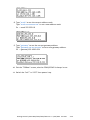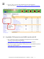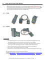
1
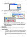
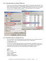
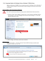
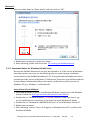
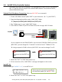
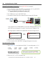
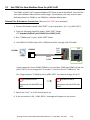
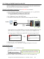
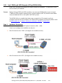
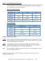
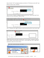
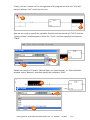
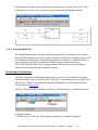
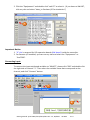
Getting Started of μPAC-5007/5107/5207/5307 This manual is intended for integrators, programmers, and maintenance personnel who will be installing and maintaining a PAC-5x07 controller system. ISaGRAF PAC Series of ICP DAS includes: Please visit the website: www.icpdas.com > Product > Solutions > Soft PLC, ISaGRAF & Soft-GRAF HMI > ISaGRAF μPAC: iPAC: WinPAC: ViewPAC: XPAC: μPAC-7186EG/PEG, μPAC-5xx7 Series, I-7188EG, I-7188XG, iP-8xx7 Series, I-8xx7 Series, WP-8xx7 Series, WP-5xx7 Series VP-2xW7/4xx7 Series, VP-2117 XP-8xx7-CE6 Series, XP-8xx7-Atom-CE6 Series Legal Liability ICP DAS CO., LTD. assumes no liability for any and all damages that may be incurred by the user as a consequence of this product. ICP DAS CO., LTD. reserves the right to change this manual at any time without notice. ICP DAS CO., LTD. constantly strives to provide our customers with the most reliable and accurate information possible regarding our products. However, ICP DAS CO., LTD. assumes no responsibility for its use, or for any infringements of patents or other rights of third parties resulting from its use. Trademark & Copyright Notice The names of products are used for identification purposes only, and are the registered trademarks of their respective owners or companies. Technical Service: Please contact local agent or email problem-report to [email protected]. New information can be found at www.icpdas.com. FAQ: www.icpdas.com > Support > FAQ > ISaGRAF Soft-Logic PAC Written by Chun Tsai, Spike Huang & Janice Hong, R&D dept., ICP DAS Copyright © May. 2010, by ICP DAS CO., LTD. All Rights Reserved. Getting Started: PAC-5007/5107/5207/5307 Ver. 1.2, 09/2015 ICP DAS 1 Table of Contents Getting Started of μPAC-5007/5107/5207/5307 ...................................................................... 1 Table of Contents .................................................................................................................... 2 Reference Guide ...................................................................................................................... 4 I/O Modules Selection Guide for μPAC-5x07 Series ................................................................. 5 Specifications: μPAC-5x07(D)................................................................................................... 6 Chapter 1. Typical Application............................................................................................. 1-1 1.1 μPAC-5007/5107/5207/5307 Comparison Table................................................ 1-1 1.2 Local & Remote I/O Application .......................................................................... 1-1 1.3 Multi-HMI Application ......................................................................................... 1-2 1.4 Active Data Acquisition & Auto-Report System .................................................. 1-2 1.5 Data Logger ......................................................................................................... 1-3 1.6 Modbus Converter of Remote I/O Modules ....................................................... 1-3 1.7 Data Exchange through Ethernet or RS-485 ....................................................... 1-4 1.8 Send Email with an Attached File ........................................................................ 1-4 1.9 SMS: Short Message Service ............................................................................... 1-5 1.10 Integrate with CAN/CANopen Devices and Sensors ........................................... 1-5 1.11 Connecting other Device via Modbus Master .................................................... 1-6 1.12 GPS Applications: ISaGRAF PAC plus I-87211W or GPS-721 ............................... 1-7 1.13 ZigBee Wireless Solution ..................................................................................... 1-8 Chapter 2. Software Programming ...................................................................................... 2-1 2.1 Step 1 – Installing ISaGRAF Software .................................................................. 2-1 2.1.1: The Hardware Protection Device (Dongle & USB Key-Pro) ...................... 2-2 2.1.2: Important Notice for Window 2000 Users ............................................... 2-3 2.1.3: Important Notice for Window NT Users .................................................. 2-3 2.1.4: Important Notice for Windows Vista or Windows 7 (32-bit) Users ......... 2-4 2.1.5: Important Notice for Windows (64-bit) Users ......................................... 2-5 2.1.6: Important Setting for Using Variable Arrays ............................................ 2-6 2.2 Step 2 – Installing ICP DAS Utilities for ISaGRAF ................................................. 2-7 Chapter 3. Hardware System & Setting ............................................................................... 3-1 3.1 Connect Your PC to COM1 Port........................................................................... 3-1 3.2 Connect Your PC to COM2 Port........................................................................... 3-2 3.3 Connect Your PC to Ethernet Port....................................................................... 3-3 3.4 How to Update Hardware Driver ........................................................................ 3-5 Getting Started: PAC-5007/5107/5207/5307 Ver. 1.2, 09/2015 ICP DAS 2 3.5 Set NET-ID for Controller System ........................................................................ 3-8 3.6 Set Baud Rate for COM1 ..................................................................................... 3-9 3.7 Set COM1 to Non-Modbus-Slave for μPAC-5x07 ..............................................3-10 3.8 Set COM2 or COM3 as a Modbus RTU Slave Port .............................................3-12 3.9 Set IP & MASK & Gateway for μPAC-5x07 ........................................................3-14 3.10 Delete an ISaGRAF Project from the PAC ..........................................................3-16 3.11 Set I-7000 and I-87K Remote I/O by DCON Utility ............................................3-17 3.12 Link to I-7000 and I-87K Remote I/O Modules .................................................3-21 3.13 Create Two Modbus Master/Slave Links ..........................................................3-22 3.14 Link to HMI Interface Device .............................................................................3-23 3.15 Backup & Restore an ISaGRAF Project ..............................................................3-24 3.16 Dimension & Mounting for μPAC-5x07 .............................................................3-25 Chapter 4. ISaGRAF Demo ................................................................................................... 4-1 4.1 Writing a Simple ISaGRAF Program ..................................................................... 4-1 4.1.1: Start ISaGRAF – Project Management ...................................................... 4-2 4.1.2: Creating an ISaGRAF Project Group ......................................................... 4-2 4.1.3: Creating a New ISaGRAF Project .............................................................. 4-3 4.1.4: Declaring the ISaGRAF Project Variables .................................................. 4-4 4.1.5: Creating the Example LD Program ........................................................... 4-8 4.1.6: Editing the Example "LD1" Program ......................................................... 4-9 4.1.7: Connecting the I/O .................................................................................4-12 4.2 Compiling & Simulating the Example Project ...................................................4-15 4.2.1: Compiling the LD Project! .......................................................................4-15 4.2.2: Simulating the LD Project .......................................................................4-16 4.2.3: Running the Simulation Program ...........................................................4-17 4.3 Appendix Debug & Download the Example Project ..........................................................4-20 ............................................................................................................................. 1 A. ISaGRAF User Manual & Demo Program & FAQ ........................................................... 1 A.1 The Download Page for ISaGRAF Resource ................................................. 1 A.2 Using Modbus TCP/IP protocol to control ISaGRAF controllers with VB? .. 2 B. 10-ch Thermocouple Input Module .............................................................................. 3 B.1 I-7018Z ......................................................................................................... 3 B.2 I-87018Z ....................................................................................................... 3 C. XW-107 (I/O Expansion Board) ..................................................................................... 4 Getting Started: PAC-5007/5107/5207/5307 Ver. 1.2, 09/2015 ICP DAS 3 Reference Guide ISaGRAF Resource on the Internet: Newly updated ISaGRAF IO libraries, drivers, demo, and manuals can be found at www.icpdas.com > Product > Solutions > Soft PLC, ISaGRAF & Soft-GRAF HMI > ISaGRAF ISaGRAF User’s Manual (English Manual): CD-ROM: \napdos\isagraf\8000\english_manu\ "user_manual_i_8xx7.pdf" & "user_manual_i_8xx7_appendix.pdf" ISaGRAF 進階使用手冊 (Chinese Manual): CD-ROM: \napdos\isagraf\8000\chinese_manu\ "chinese_user_manual_i_8xx7.pdf" & "chinese_user_manual_i_8xx7_appendix.pdf" or ISaGRAF Web > Download - Manual Hardware Manual: PAC-5x07: CD\NAPDOS\uPAC-5000\document\ or ftp://ftp.icpdas.com.tw/pub/cd/8000cd/napdos/upac-5000/document/ Industrial Ethernet Switch: NS-205 / NS-208 / NS-205PSE Best choice for Industrial Ethernet Communication. www.icpdas.com > Product > Solutions > Industrial Ethernet Switch & Fber Switch > Unmanaged Ethernet Switches Note: The NS-205PSE is a PoE Switch. FAQ: Please refer to our website www.icpdas.com > Support > FAQ > ISaGRAF Soft-Logic PAC or ISaGRAF Web > Download - FAQ. Getting Started: PAC-5007/5107/5207/5307 Ver. 1.2, 09/2015 ICP DAS 4 I/O Modules Selection Guide for μPAC-5x07 Series The μPAC-5x07 series PAC supports one optional XW-board (open the cover to plug it into the PAC) and RS-485 remote I/O modules. Please refer to the list in the next page or follow the below steps to get the new list. 1. www.icpdas.com 2. Click here to go to the ISaGRAF page 3. Data Sheet Getting Started: PAC-5007/5107/5207/5307 Ver. 1.2, 09/2015 ICP DAS 5 Specifications: μPAC-5x07(D) Models μPAC-5007(D) μPAC-5107(D) μPAC-5207(D) μPAC-5307(D) System Software OS MiniOS7 (DOS-like embedded operating system) Development Software ISaGRAF Ver. 3 IEC 61131-3 standard Languages LD, ST, FBD, SFC, IL & FC ISaGRAF Software Max. Code Size 64 KB Scan Time 2 ~ 25 ms for normal program; 10 ~ 125 ms (or more) for complex or large program CPU Module CPU 80186, 80 MHz SRAM 768 KB Flash 512 KB microSD Expansion Yes (but ISaGRAF doesn't support) Battery Backup SRAM 512 KB ; data valid up to 5 years (for retain variables) EEPROM 16 KB NVRAM 31 Bytes (battery backup, data valid up to 10 year) RTC (Real Time Clock) Provide second, minute, hour, date, day of week, month, year 64-bit Hardware Serial Number Yes, for Software Copy Protection Watchdog Timers Yes (0.8 second) Communication Ports Ethernet RJ-45 x 1, 10/100 Base-TX (Auto-negotiating, Auto MDI/MDI-X, LED indicators) COM 1 RS-232 (TxD, RxD, RTS, CTS, GND), non-isolated, Speed: 115200 bps max. COM 2 RS-485 (Data+, Data-) with internal self-tuner ASIC; non-isolated, Speed: 115200 bps max. LED Indicator Programmable LED Indicators 2 LED Display 5-digit 7-segment LED display for (D) versions Hardware Expansion I/O Expansion Bus Yes (for one XW-Board only) Mechanical Dimensions (W x H x D) 91 mm x 123 mm x 52 mm Installation DIN-Rail Mounting Getting Started: PAC-5007/5107/5207/5307 Ver. 1.2, 09/2015 ICP DAS 6 Models μPAC-5007(D) μPAC-5107(D) μPAC-5207(D) μPAC-5307(D) Environmental Operating Temperature -25 ~ +75°C Storage Temperature -30 ~ +80°C Ambient Relative Humidity 10 ~ 90% RH (non-condensing) Power Input Range +12 ~ +48 VDC Isolation - Redundant Power Inputs Yes Protection Power reverse polarity protection Frame Ground Yes (for ESD Protection) Power Consumption 2 W; 2.5 W for (D) version Wireless Wireless Communication - GPS 2G (GPRS) 3G (WCDMA) GPS: μPAC-5107(D) Channels 32 (all-in-view tracking) Sensitivity -159 dBm Acquisition Rate Cold start: 42 seconds; warm start: 35 seconds; reacquisition rate: 0.1 second Accuracy Position: 25 m CEP (S/A off); Velocity: 0.1 second (S/A off); Time: ± 1 ms Protocol NMEA 2G (GPRS): μPAC-5207(D) Band 850/900/1800/1900 MHz GPRS Multi-slot Class 10/8 GPRS Mobile Station Class B GPRS Class 10 Max. 85.6 kbps CSD Up to 14.4 kbps Compliant to GSM phase Class 4 (2 W @ 850/900 MHz); 2/2+ Class 1 (1 W @ 1800/1900 MHz) Coding Schemes CS 1, CS 2, CS 3, CS 4 SMS Text and PDU mode 3G (WCDMA): μPAC-5307(D) Band UMTS : 2100/1900/850 MHz Data Transfer UMTS / HSDPA / HSUPA Upload: Max. 5.76 Mbps; Download: Max. 7.2 Mbps Getting Started: PAC-5007/5107/5207/5307 Ver. 1.2, 09/2015 ICP DAS 7 Protocols (Note that certain protocols require optional devices) NET ID 1 ~ 255, user-assigned by software Modbus RTU/ASCII Master Protocol A max. of 2 Ports: COM1, COM2 and COM3 (*). (To connect to other Modbus Slave devices) A max. of Modbus_xxx Function Block amount for 2 ports: 128. Modbus RTU Slave Protocol A max. of 2 COM Ports, COM1 and one of (COM2, COM3) (*). (For connecting ISaGRAF, PC/HMI/OPC Server and HMI panels.) Modbus TCP/IP Protocol Ethernet port supports Modbus TCP/IP Slave Protocol for connecting ISaGRAF & PC/HMI up to 6 connections. User-defined Protocol Custom protocols can be applied at COM1, COM2 and COM3 ~ 8 using Serial communication function blocks. (*) Remote I/O One of COM2 or COM3: RS-485 supports I-7000 I/O modules, I-87K base + I-87K Serial I/O boards, or RU-87Pn + I-87K High Profile I/O boards as remote I/O. A max. of 64 I-7000/87K remote I/O modules can connect to one PAC. (*) Fbus Built-in COM2 Port to exchange data between ICP DAS's ISaGRAF PACs. Ebus Used to exchange data between ICP DAS ISaGRAF Ethernet PACs via the Ethernet port. Send Email Provide functions to send email to a max. of 10 receivers with a single attached file via the Ethernet port through internet. The max. of file size is about 488 KB. SMS: Short Message Service One of COM1 or COM3 or COM4 (RS-232) (*) can link to a GSM Modem to support SMS. The user can request data/control the controller via a cellular phone. The controller can also send data and alarms to the user’s cellular phone. Optional GSM Modem: GTM-201-RS232 (850/900/1800/1900 GSM/GPRS External Modem) Note: μPAC-5207, 5307 has built-in GPRS, no external GSM/GPRS modem required. Redundancy Solution Two PACs plug with XW107 in slot0. One is Master, one is Slave. Master handles all inputs & outputs at run time. If Master is damaged (or power off), Slave will take over the control of Bus7000b. If Master is alive from damaged (or power up again), it takes the control of Bus7000b again. The change over time is about 5 seconds. Control data is exchanging via Ebus (if using a cross cable, no require any Ethernet Switch). All I/O should be RS-485 I/O except the status I/O in the slot 0: XW107. CAN/CANopen COM1 or COM3~8 can connect to one I-7530 (converter: RS-232 to CAN) to support CAN/CANopen devices and sensors. One iP-8xx7 supports a max. of 3 RS-232 ports to connect a max. of 3 I-7530.(*) (FAQ-086) FTP Client Enable the FTP Client to upload files from the PAC to a remote FTP server on a PC. (FAQ-151) Getting Started: PAC-5007/5107/5207/5307 Ver. 1.2, 09/2015 ICP DAS 8 Optional I/O Functions (Refer to the ISaGRAF PAC I/O Selection Guide for I/O Module list) PWM Output Pulse Width Modulation Output All XW-Board DO series support PWM output. Max. 8 channels for one controller. 500 Hz max. for Off = 1 & On = 1 ms Output square wave: Off: 1 ~ 32767 ms, On: 1 ~ 32767 ms Counters Parallel DI Counter All XW-Board DI series support counter. Max. 8 channels for one controller. Counter value: 32-bit 500 Hz max. Min. ON & OFF width must > 1 ms Remote DI Counter All remote I-7K/I-87K DI modules support counters. 100 Hz max. value: 0 ~ 65535 Remote High Speed Counter I-87082: 100 kHz max., 32-bit * Note: COM3 ~ COM8 are resided at the optional XW-Board series if it is plugged inside the μPAC-5xx7. (Will be available.) * ISaGRAF FAQ: www.icpdas.com > Support > FAQ > ISaGRAF Soft-Logic PAC * ICP DAS recommends using NS-205/NS-208 or RS-405/408 (Ring Switch) Industrial Ethernet Switches. Getting Started: PAC-5007/5107/5207/5307 Ver. 1.2, 09/2015 ICP DAS 9 Chapter 1. Typical Application 1.1 μPAC-5007/5107/5207/5307 Comparison Table Model CPU Flash SRAM Memory 3G RS-232/ Ethernet GPS GPRS Expansion (WCDMA) RS-485 μPAC-5007 μPAC-5107 μPAC-5207 80186 80M 512 KB 768 KB 512 KB Battery backup SRAM 10/100 Base TX μPAC-5307 - - - Yes - - - Yes - - - Yes 1/1 All of the following applications are applicable to μPAC-5x07(D) PAC. The μPAC-5007D is used in following diagram. 1.2 Local & Remote I/O Application Advantage of using RU-87P4/P8 + I-87K I/O modules: Hot-Swap Auto-Configuration at Run Time Plug & Play at Run Time NOTE: RU-87Pn support only High profile I-87K I/O module. Nearly 100 choices of Remote I/O modules: I-7000 & I-87K. There are several X-Boards to expand more I/O channels, COM Ports, SRAM memory, etc. Getting Started: PAC-5007/5107/5207/5307 Ver. 1.2, 09/2015 ICP DAS 1-1 1.3 Multi-HMI Application 1.4 Active Data Acquisition & Auto-Report System μPAC-5x07 can use UDP/IP Client protocol to auto-report acquisition data & control data to local or to remote internet PC/Server. Advantage: Each PAC in the different location doesn't require a fixed Internet IP. More at www.icpdas.com > Support > FAQ > ISaGRAF Soft-Logic PAC > FAQ-065 Getting Started: PAC-5007/5107/5207/5307 Ver. 1.2, 09/2015 ICP DAS 1-2 1.5 Data Logger ICP DAS provides a freeware “UDLoader.exe” to load the data stored in battery-backup SRAM via RS-232 or Ethernet port. 1.6 Modbus Converter of Remote I/O Modules μPAC-5x07 can be a Modbus RTU Serial and TCP/IP converter of I-7000 & I-87K series I/O modules. Getting Started: PAC-5007/5107/5207/5307 Ver. 1.2, 09/2015 ICP DAS 1-3 1.7 Data Exchange through Ethernet or RS-485 Each μPAC-5x07 can send or receive data to each other via the Ebus (Ethernet) or Fbus (RS-485) communication mechanism on the same network. 1.8 Send Email with an Attached File μPAC-5x07 can send Email with one attached file via Ethernet Port. The maximum file size is about 488K bytes and one Email can send to 10 receivers at one sending. Getting Started: PAC-5007/5107/5207/5307 Ver. 1.2, 09/2015 ICP DAS 1-4 1.9 SMS: Short Message Service Short message can be sent in multiple language format (such as Chinese, English... others) More at www.icpdas.com > Support > FAQ > ISaGRAF Soft-Logic PAC > FAQ-111 μPAC-5207/5307 has built-in GPRS, no external GSM/GPRS modem required. 1.10 Integrate with CAN/CANopen Devices and Sensors μPAC-5x07 supports max. 3 I-7530 (RS-232 to CAN) converters. More at www.icpdas.com > Support > FAQ > ISaGRAF Soft-Logic PAC > FAQ-086 Getting Started: PAC-5007/5107/5207/5307 Ver. 1.2, 09/2015 ICP DAS 1-5 1.11 Connecting other Device via Modbus Master μPAC-5x07 supports up to 2 COM ports of Modbus RTU/ASCII Master protocol to integrate with other Modbus devices. RS-485: RS-232: Note: COM3 ~ COM8 is optional from XW-Board (XW5xx), RS-232/RS-422/RS-485 expansion board. μPAC-5x07 can plug one I/O Expansion board inside the main box. To install it, user has to loosen the screw, remove the shell of μPAC-5x07 and then plug in the XW-board. Please refer to below web for new products: www.icpdas.com > Product > Solutions > PAC > WP-5000 > I/O Expansion Boards (XW-board). Getting Started: PAC-5007/5107/5207/5307 Ver. 1.2, 09/2015 ICP DAS 1-6 1.12 GPS Applications: ISaGRAF PAC plus I-87211W or GPS-721 μPAC-5007/5207/5307 can support one I-87211W card or GPS-721 as GPS I/O. (The PAC can communicate with the GPS-721 by RS-485/232; the I-87211W can plug into Remote I/O Expansion units) For doing auto-time-synchronization and getting the local longitude and latitude. More at www.icpdas.com > Support > FAQ > ISaGRAF Soft-Logic PAC > FAQ-107 GPS Receiver: www.icpdas.com > Product > Solutions > Industrial Wireless Communication > GPS Products Note: μPAC-5107 has built-in GPS function. Getting Started: PAC-5007/5107/5207/5307 Ver. 1.2, 09/2015 ICP DAS 1-7 1.13 ZigBee Wireless Solution ISaGRAF PAC plus ZB-2550P and ZB-2551P (ZigBee to RS-232/485 Converters) can apply wireless communication, reduce the wiring cost, and achieve the mission of remote I/O control and data acquisition. More at www.icpdas.com > Support > FAQ > ISaGRAF Soft-Logic PAC > FAQ-110 Getting Started: PAC-5007/5107/5207/5307 Ver. 1.2, 09/2015 ICP DAS 1-8 Chapter 2. Software Programming 2.1 Step 1 – Installing ISaGRAF Software There are two kinds of software to be installed in the PC before the user can program on the ISaGRAF PAC system. They are: A. ISaGRAF Workbench and B. ICP DAS Utilities for ISaGRAF The user has to purchase at least one set of ISaGRAF workbench Version 3 (ISaGRAF-256) to install on his PC to edit, download, monitor & debug the controller system. Item (B) is free and it is burned inside the CD-ROM which is delivered with the PAC-5x07. Operating system Requirements: One of the following computer operating systems must be installed on the target computer system before you can install the ISaGRAF Workbench software program. Windows 95 / Windows 98 / Windows 2000 Windows NT Version 3.51 or Windows NT Version 4.0 Windows XP or Vista or Windows 7 (Please refer to www.icpdas.com > Support > FAQ > ISaGRAF Soft-Logic PAC > FAQ-117) Steps to Installing the ISaGRAF Workbench: If your operating system is Windows Vista or Windows 7 (32-bit), please refer to 2.1.4. If your operating system is Windows 7 (64-bit), please refer to 2.1.5. Insert the ISaGRAF Workbench CD into your CD-ROM drive. If your computer does not have the auto-start feature active, use the Windows Explorer and go to the CD-ROM drive where the Workbench CD is installed, then double-click on the “install.bat” file listed on the ISaGRAF CD. If the “install.bat” file is not found on your ISaGRAF CD, then double-click on the “ISaGRAF.exe” file to start the installation process. Select the language. Recommend to use "English" because this manual uses English version. Getting Started: PAC-5007/5107/5207/5307 Ver. 1.2, 09/2015 ICP DAS 2-1 To begin the ISaGRAF 3.x software program, click on the Windows “Start” button, then on “Programs”, and you should see the ISaGRAF program group as illustrated below. You could click “Projects” to start the program. 2.1.1: The Hardware Protection Device (Dongle & USB Key-Pro) You must install the hardware protection device (dongle) provided with the ISaGRAF software on your computers parallel port to for the ISaGRAF program to achieve fully authorized functionality. (ISaGRAF-32-E & ISaGRAF-32-C DO NOT need dongle or USB Key-Pro.) 1. 2. While using ISaGRAF and the dongle is plugged well, if the “Help” – “About” says “Maximum number of IO variables: 32”, it means ISaGRAF workbench cannot find the dongle well. Please reset your PC and then check the “Help” – “About” again. If it still displays “Maximum number of IO variables: 32”, the driver may not be installed well. Please do the following steps. Dongle Protection: Please execute the ISaGRAF CD_ROM \Sentinel5382\setup.exe for ISaGRAF-80 or \Sentinel\setup.exe for other ISaGRAF version and then reset the PC again. USB Key-Pro Protection: 1. To make your PC recognize the ISaGRAF USB protection-key, please un-plug the USB protection-key from your USB port first, then run “\Sentinel\SSD5411-32bit.exe” in the ISaGRAF 3.55 CD-ROM (or later version) after you have installed the ISaGRAF. Then please reset your PC. 2. To run ISaGRAF Ver. 3.5x, please always plug the USB protection-key in the PC’s USB port. Getting Started: PAC-5007/5107/5207/5307 Ver. 1.2, 09/2015 ICP DAS 2-2 2.1.2: Important Notice for Window 2000 Users If you close some ISaGRAF windows, it holds about 20 ~ 40 seconds (No response). This may caused by the procedure “CTFMON.EXE” of Windows 2000. First click on “Ctrl & Alt & Del” at the same time to stop the “CTFMON.EXE” process, and then you may create a shortcut for the “ISaGRAF project manager”. And then check on “run in separate memory space” option in the shortcut property. 2. 1. 2.1.3: Important Notice for Window NT Users If your computer is using the Windows NT operating system, you will need to add one line to the “isa.ini” file in the ISaGRAF Workbench “EXE” subdirectory. C:\ISAWIN\EXE\isa.ini You can use any ASCII based text editor (such as Notepad or UltraEdit32) to open the “isa.ini” file. Locate the [WS001] header in the “isa.ini” initialization file (it should be at the top of the file). Anywhere within the [WS001] header portion of the “isa.ini” initialization file, add the entry shown below within the [WS001] header: [WS001] NT=1 Isa=C: \ISAWIN IsaExe=C: \ISAWIN\EXE Group=Samples IsaApl=c: \isawin\smp IsaTmp=C: \ISAWIN\TMP Getting Started: PAC-5007/5107/5207/5307 Ver. 1.2, 09/2015 ICP DAS 2-3 2.1.4: Important Notice for Windows Vista or Windows 7 (32-bit) Users Before installing the ISaGRAF; If your operating system is Windows Vista or Windows 7 (32-bit) , please change the User Account Control settings to avoid some of the setup restrictions. How to disable “UAC” (User Account Control) ? The “UAC” (User Account Control) setting requires administrator-level permission. 1. From the “Start” menu, choose “Control Panel > User Accounts and Family Safety > User Accounts”, then click “Change User Account Control settings” or “Turn User Account Control on or off”. 2. After clicking, it will show up the screen as below. Windows Vista: Uncheck the option – “Use User Account Control (UAC) to help you protect your computer”and then click on “OK”. Getting Started: PAC-5007/5107/5207/5307 Ver. 1.2, 09/2015 ICP DAS 2-4 Windows 7: Move the slider down to “Never Notify” and then click on “OK”. 3. Reboot your computer to apply the change. 4. After rebooting, please refer to section 2.1 Installing the ISaGRAF Software. 2.1.5: Important Notice for Windows (64-bit) Users Because the ISaGRAF Workbench can only be installed on a 32-bit version of Windows operating system, users can use the following ways to create a proper installation environment for the ISaGRAF Workbench 3.55. If using Windows XP Mode that can be installed on 64-bit version of Windows 7 Professional, Enterprise, and Ultimate editions. If using VMware Workstation/Player that can be installed on any 64-bit version of Windows OS (e.g., Windows 7 or Windows 8). Using Virtual PC and XP Mode: 1. Download Windows Virtual PC and Windows XP Mode installers from the Windows 2. 3. 4. 5. Virtual PC Web site (http://go.microsoft.com/fwlink/?LinkID=160479) Double-click on "WindowsXPMode_nn-NN.exe” (where nn-NN is the locale, e.g. en-US) and follow the instructions in the wizard to install Windows XP Mode. Double-click on "Windows6.1-KB958559-x64.msu” to install Windows Virtual PC. Reboot your computer. After rebooting, click on "Star > All Programs > Windows Virtual PC” and then click Windows XP Mode. Getting Started: PAC-5007/5107/5207/5307 Ver. 1.2, 09/2015 ICP DAS 2-5 6. Follow the instructions in the wizard to complete Windows XP Mode Setup and Configuration. Record the password that is provided during the Setup because it is required to log on to your virtual machine. 7. Now, go back to Section 2.1 to install the ISaGRAF. Using VMware Workstation/Player: 1. Download and install VMware Workstation 10 (trail version) on VMware website. https://my.vmware.com/web/vmware/info/slug/desktop_end_user_computing/vmware_workstatio n/10_0 2. Create a virtual machine running Windows XP (32-bit, SP3). 3. Install ISaGRAF Workbench 3.55 on a virtual machine. 4. Install ISaGRAF I/O Library on a virtual machine. 5. The related settings for a virtual machine. 6. Install USB dongle driver on a virtual machine. More at www.icpdas.com > Support > FAQ > ISaGRAF Soft-Logic PAC > FAQ-174 2.1.6: Important Setting for Using Variable Arrays Please add two more lines on the top of the c:\isawin\exe\isa.ini file to enable the usage of variable arrays. [DEBUG] Arrays=1 Getting Started: PAC-5007/5107/5207/5307 Ver. 1.2, 09/2015 ICP DAS 2-6 2.2 Step 2 – Installing ICP DAS Utilities for ISaGRAF “ICP DAS Utilities for ISaGRAF” consists of 3 major functions: Note: I/O libraries (for all ISaGRAF PAC) Modem_Link utility Auto-scan I/O utility Make sure you have installed the ISaGRAF Workbench program, IF NOT, please refer to Ch 2.1 Step 1 before continuing. There is a CD-ROM supplied with each of the PAC-5x07 PAC with the “ICP DAS Utilities for ISaGRAF”. Please insert the CD-ROM into your CD-ROM drive. Then run CD-ROM: \napdos\isagraf\setup.exe. Follow the steps to install it. If “ICP DAS Utilities for ISaGRAF” is not in your CD-ROM, please refer to the website www.icpdas.com > Product > Solutions > Soft PLC, ISaGRAF & Soft-GRAF HMI > ISaGRAF > Driver , then find “ICP DAS Utilities for ISaGRAF” to download “io_lib.zip”. Getting Started: PAC-5007/5107/5207/5307 Ver. 1.2, 09/2015 ICP DAS 2-7 Chapter 3. Hardware System & Setting 3.1 Connect Your PC to COM1 Port The COM1 port of the μPAC-5x07 is a Modbus Slave port which can talk with HMI software or for the ISaGRAF workbench to download the ISaGRAF project. COM1: RS-232: One PC/HMI can only link to COM1: RS-232 port of one μPAC-5x07. PC / HMI μPAC-5x07 COM1: RS-232 19200, N, 8, 1 COM1: RS-232 Pin Assignments PC / HMI μPAC-5x07 9-Pin D-Sub COM1 RxD 2 TxD TxD 3 RxD GND 5 GND RTS CTS For the ISaGRAF Workbench RS-232 communications to operate properly, only the RXD, TXD, and the GND signals are used. If your PC is running a hardware device or software program that uses the RTS and CTS signals, then you will need to wire the RTS-CTS signals together. Getting Started: PAC-5007/5107/5207/5307 Ver. 1.2, 09/2015 ICP DAS 3-1 3.2 Connect Your PC to COM2 Port One PC or HMI can link through COM2: RS-485 port to MANY μPAC-5x07 if each of them on the same RS-485 network has a unique NET-ID. COM2: RS-485: I-7520R RS-232/485 Converter COM2: RS-485 19200, 8, N, 1 PC / HMI RS-232 NET-ID= 1 ID=2 ID=3 μPAC-5x07 COM2: RS-485 Pin Assignments PC / HMI RS-232 Note: I-7520R (RS-232/485 Converter) COM2: RS-485 μPAC-5x07 μPAC-5x07 COM2: RS-485 COM2: RS-485 D+ D- D+ D- D+ D- Please make sure each μPAC-5x07 on the same RS-485 network has distinct NET-ID. Refer to Section 3.4 to set the NET-ID. Getting Started: PAC-5007/5107/5207/5307 Ver. 1.2, 09/2015 ICP DAS 3-2 3.3 Connect Your PC to Ethernet Port The Ethernet port of the μPAC-5x07 PAC provides Modbus TCP/IP Slave protocol. It can be used to connect to the PC or HMI software. Up to 6 PC/HMI can talk to one μPAC-5x07 at the same time through the Ethernet port. Industrial Ethernet Switch NS-205/208(PSE) PC / HMI Ethernet μPAC-5x07 Port No. = 502 Before you can download an ISaGRAF application to the μPAC-5x07 PAC using the Ethernet port, you must first setup the Ethernet port to properly communicate with the host PC. μPAC-5x07: Set IP address, Mask and Gateway. Please refer to Section 3.9. PC: First open an ISaGRAF project and select a program you wish to communicate between your PC and the μPAC-5x07 PAC system. Next, click on "Link Setup" button in the project screen as shown below. A "PC-PLC Link Parameters" dialog box will appear as shown below. Select the "Ethernet" communications option and click on "Setup" button. Getting Started: PAC-5007/5107/5207/5307 Ver. 1.2, 09/2015 ICP DAS 3-3 After you click on "Setup" button, an "Ethernet Link Parameters" dialog box will appear. Set the "Port Number" to "502" and enter the Internet address (IP) of your μPAC-5x07 PAC. (Please refer to Section 3.9) Once you have entered the appropriate information, click on "OK" button, and now you have configured your PC to communicate with the μPAC-5x07 through the Ethernet port. Multi-Clients Connection to μPAC-5x07 Each μPAC-5x07 has an IP address and with a fixed Ethernet port No. 502. Up to 6 PCs can link to one PAC throughout Ethernet (Modbus TCP/IP protocol). Another PC or MMI can link to COM1: RS-232 port (Modbus RTU protocol). Therefore the maximum number of clients can be linked is 7. PC/HMI Modbus TCP/IP Modbus RTU PC/HMI MMI μPAC-5x07 IP1 Getting Started: PAC-5007/5107/5207/5307 Ver. 1.2, 09/2015 ICP DAS IP2 3-4 3.4 How to Update Hardware Driver Our newly released driver can be obtained from the below website. www.icpdas.com > Product > Solutions > Soft PLC, ISaGRAF & Soft-GRAF HMI > ISaGRAF > Driver Steps: We use ver. 1.00 of μPAC-5307’s driver as an example to show how to view and upgrade the driver. Download the Driver: 1. Create a file folder named "μPAC-5307" in your hard drive. (Ex. "c:\ μPAC-5307") 2. Copy the following listed files under CD: \Napdos\ISaGRAF\μPAC-5000\Driver\5307\1.00\ or download the zip file from website of www.icpdas.com > Product > Solutions > Soft PLC, ISaGRAF & Soft-GRAF HMI > ISaGRAF > Driver. (μPAC-5307 ver. 1.00, please extract the file.) 1. 2. 3. 4. 5. 6. 7188xw.exe 7188xw.f4 7188xw.ini autoexec.bat 5k090903.img isa5307.exe Future version may not use the same img file. 3. Run "7188xw.exe" in your hard drive. A "7188xw" screen will appear. (Press F1 if need help) Hardware Connection & Setting: 4. Link COM1 or COM2 of your PC to COM1 of the PAC through a RS-232 cable. PC/HMI RxD TxD GND CA0910 OFF PWR1 P.GND ON Note: If your computer has no COM1/COM2 or you use other COM (like COM5) to link the μPAC-5307, you can change the “C number” in the first line of “7188xw.ini” file. Getting Started: PAC-5007/5107/5207/5307 Ver. 1.2, 09/2015 ICP DAS 3-5 EX: Using computer’s COM5 to link to μPAC-5307. As shown below: C1 B115200 P0 D8 S1 F Xautoexec.bat Xisa5307.exe w25 C5 B115200 P0 D8 S1 F Xautoexec.bat Xisa5307.exe w25 5. Switch the “Init*” to “ON” then power it up. 6. If the connection is OK, “uPAC-5001>” messages will appear on the screen. Upgrade ISaGRAF Embedded Driver: 7. Press "F4" to auto download the following files and reboot system. "autoexec.bat", " isa5307.exe ", "5k090903.img" ** Please Wait about 60 SEC. to update ISaGRAF system and DO NOT Remove the Power. ** 8. When the system automatically reboot, you have completed the update. Type "dir" to make sure "autoexec.bat" and "isa5307.exe" have been downloaded. Getting Started: PAC-5007/5107/5207/5307 Ver. 1.2, 09/2015 ICP DAS 3-6 View the OS Version & Date: 9. Type "ver" to see the current OS version and date. View the Driver Version & PAC Settings: 10. Type "isa5307 *p=" to see the current driver version, PAC settings and instruction description. Note 1: Please depend on the PAC model to type the instruction. (Ex. isa5307 *p=) Note 2: After typing this instruction, you have to reboot to continue other step. 11. Press “ALT_X” to exit the "7188xw" screen. 12. Switch the “Init*” to “OFF” then power it up. Getting Started: PAC-5007/5107/5207/5307 Ver. 1.2, 09/2015 ICP DAS 3-7 3.5 Set NET-ID for Controller System Each μPAC-5x07 has a NET-ID Number. The valid Number is from 1 to 255. The default No. is 1. Net-ID must be unique in the same RS-485 network. To set the NET-ID No., please follow below steps. Related Files & Hardware Connection: (We use μPAC-5307 as an example) 1. Create a file folder named "μPAC-5307" in your hard drive. (Ex. "c:\ μPAC-5307") 2. Copy the following listed files under “μPAC-5307” folder: CD: \Napdos\ISaGRAF\μPAC-5000\Driver\5307\1.00\ 3. Run "7188xw.exe" in your “μPAC-5307” folder. 4. Link COM1 or COM2 of your PC to COM1 of the PAC through a RS-232 cable. PC/HMI RxD TxD GND CA0910 OFF PWR1 P.GND ON If your computer has no COM1/COM2 or you use other COM (like COM5) to link the μPAC-5307, you can change the “C number” in the first line of “7188xw.ini” file. EX: Using computer’s COM5 to link to μPAC-5307. You need to change C1 to C5. C1 B115200 P0 D8 S1 F Xautoexec.bat Xisa5307.exe w25 C5 B115200 P0 D8 S1 F Xautoexec.bat Xisa5307.exe w25 5. Switch the “Init*” to “ON” then power it up. 6. If the connection is OK, “uPAC-5001>” messages will appear on the screen. Set NET- ID: 7. Type "isa5307 *s= 2", to set NET-ID to 2. Please type the instruction according to the controller model. (Ex. isa5307 *s=2) 8. Switch the “Init*” to “OFF” then power it up. Getting Started: PAC-5007/5107/5207/5307 Ver. 1.2, 09/2015 ICP DAS 3-8 3.6 Set Baud Rate for COM1 Related Files & Hardware Connection: (We use μPAC-5307 as an example) 1. Create a file folder named "μPAC-5307" in your hard drive. (Ex. "c:\ μPAC-5307") 2. Copy the following listed files under “μPAC-5307” folder: CD: \Napdos\ISaGRAF\μPAC-5000\Driver\5307\1.00\ 3. Run "7188xw.exe" in your “μPAC-5307” folder. 4. Link COM1 or COM2 of your PC to COM1 of the PAC through a RS-232 cable. RxD TxD GND CA0910 PC/HMI OFF PWR1 P.GND ON If your computer has no COM1/COM2 or you use other COM (like COM5) to link the μPAC-5307, you can change the “C number” in the first line of “7188xw.ini” file. EX: Using computer’s COM5 to link to μPAC-5307. You need to change C1 to C5. C1 B115200 P0 D8 S1 F Xautoexec.bat Xisa5307.exe w25 C5 B115200 P0 D8 S1 F Xautoexec.bat Xisa5307.exe w25 5. Switch the “Init*” to “ON” then power it up. 6. If the connection is OK, “uPAC-5001>” messages will appear on the screen. Start the Baud Rate Setting: 7. Type "isa5307 *b=n" to set baud rate of COM1. "n" is the setting code, n = 0 ~ 9. 1=2400, 7=115200, 2=4800, 8=300, 3=9600, 9=600, 4=19200, 0=1200 5=38400, 6=57600, Please type the instruction according to the controller model. (Ex. isa5307 *b=3) 8. Switch the “Init*” to “OFF” then power it up. Getting Started: PAC-5007/5107/5207/5307 Ver. 1.2, 09/2015 ICP DAS 3-9 3.7 Set COM1 to Non-Modbus-Slave for μPAC-5x07 The COM1 of μPAC-5x07 supports Modbus RTU Slave protocol by default. User can free it as a Non-Modbus-Slave port for other usage. For example, user may write his own defined protocol on COM1 or use COM1 as a Modbus Master port. Related Files & Hardware Connection: (We use μPAC-5307 as an example) 1. Create a file folder named "μPAC-5307" in your hard drive. (Ex. "c:\ μPAC-5307") 2. Copy the following listed files under “μPAC-5307” folder: CD: \Napdos\ISaGRAF\μPAC-5000\Driver\5307\1.00\ 3. Run "7188xw.exe" in your “μPAC-5307” folder. 4. Link COM1 or COM2 of your PC to COM1 of the PAC through a RS-232 cable. PC/HMI RxD TxD GND CA0910 OFF PWR1 P.GND ON If your computer has no COM1/COM2 or you use other COM (like COM5) to link the μPAC-5307, you can change the “C number” in the first line of “7188xw.ini” file. EX: Using computer’s COM5 to link to μPAC-5307. You need to change C1 to C5. C1 B115200 P0 D8 S1 F Xautoexec.bat Xisa5307.exe w25 C5 B115200 P0 D8 S1 F Xautoexec.bat Xisa5307.exe w25 5. Switch the “Init*” to “ON” then power it up. 6. If the connection is OK, “uPAC-5001>” messages will appear on the screen. Getting Started: PAC-5007/5107/5207/5307 Ver. 1.2, 09/2015 ICP DAS 3-10 Free COM1: 7. Type "isa5307 *f=1" to free COM1 (free COM1 as Non-Modbus-Slave) Please type the instruction according to the controller model. (Ex. isa5307 *f=1) 8. Exit the "7188xw" screen; else the COM1/COM2 is always in use. 9. Switch the “Init*” to “OFF” then power it up. Important Notice: If user wants to change COM1 back to a Modbus RTU Slave port again, follow the same steps as above and then type "isa5307 *f=0" as below. Getting Started: PAC-5007/5107/5207/5307 Ver. 1.2, 09/2015 ICP DAS 3-11 3.8 Set COM2 or COM3 as a Modbus RTU Slave Port μPAC-5x07 can install XW5xx expansion board to have a COM3 or more COM Port. User can customize one of COM2/COM3 to supports Modbus RTU Slave protocol. Note: COM2/COM3 is “Non-Modbus RTU Slave Port” by default. Related Files & Hardware Connection: (We use μPAC-5307 as an example) 1. Create a file folder named "μPAC-5307" in your hard drive. (Ex. "c:\ μPAC-5307") 2. Copy the following listed files under “μPAC-5307” folder: CD: \Napdos\ISaGRAF\μPAC-5000\Driver\5307\1.00\ 3. Run "7188xw.exe" in your “μPAC-5307” folder. 4. Link COM1 or COM2 of your PC to COM1 of the PAC through a RS-232 cable. PC/HMI RxD TxD GND CA0910 OFF PWR1 P.GND ON If your computer has no COM1/COM2 or you use other COM (like COM5) to link the μPAC-5307, you can change the “C number” in the first line of “7188xw.ini” file. EX: Using computer’s COM5 to link to μPAC-5307. You need to change C1 to C5. C1 B115200 P0 D8 S1 F Xautoexec.bat Xisa5307.exe w25 C5 B115200 P0 D8 S1 F Xautoexec.bat Xisa5307.exe w25 5. Switch the “Init*” to “ON” then power it up. 6. If the connection is OK, “uPAC-5001>” messages will appear on the screen. Getting Started: PAC-5007/5107/5207/5307 Ver. 1.2, 09/2015 ICP DAS 3-12 Set COM2 or COM3 as Modbus RTU Slave: 7. Type "isa5307 *x=PB" to set the baud rate of COM2/3 and as a Modbus RTU Slave port. "P" means the COM Port number. (P = 2 or 3), "B" means the baud rate. (B = 0 ~ 9) 1=2400, 7=115200, 2=4800, 8=300, 3=9600, 9=600, 4=19200, 0=1200 5=38400, 6=57600, Set COM2/3 baud rate and define it as a Modbus RTU "PB" = 20 ~ 29, set COM2 to Modbus Slave Port "PB" = 30 ~ 39, set COM3 to Modbus Slave Port Ex: Set COM2 as Modbus RTU Slave Port, baud rate is 19200. Please type the instruction according to the controller model. (Ex. isa5307 *x=24) 8. Exit the "7188xw" screen; else the COM1/COM2 is always in use. 9. Switch the “Init*” to “OFF” then power it up. Recovery the COM2/COM3 Setting: If you want to set COM2/COM3 as Non-Modbus RTU Slave Port, please type "isa5307 *x=f" to release it. Getting Started: PAC-5007/5107/5207/5307 Ver. 1.2, 09/2015 ICP DAS 3-13 3.9 Set IP & MASK & Gateway for μPAC-5x07 Related Files & Hardware Connection: (We use μPAC-5307 as an example) 1. Create a file folder named "μPAC-5307" in your hard drive. (Ex. "c:\ μPAC-5307") 2. Copy the following listed files under “μPAC-5307” folder: CD: \Napdos\ISaGRAF\μPAC-5000\Driver\5307\1.00\ 3. Run "7188xw.exe" in your “μPAC-5307” folder. 4. Link COM1 or COM2 of your PC to COM1 of the PAC through a RS-232 cable. PC/HMI RxD TxD GND CA0910 OFF PWR1 P.GND ON If your computer has no COM1/COM2 or you use other COM (like COM5) to link the μPAC-5307, you can change the “C number” in the first line of “7188xw.ini” file. EX: Using computer’s COM5 to link to μPAC-5307. You need to change C1 to C5. C1 B115200 P0 D8 S1 F Xautoexec.bat Xisa5307.exe w25 C5 B115200 P0 D8 S1 F Xautoexec.bat Xisa5307.exe w25 5. Switch the “Init*” to “ON” then power it up. 6. If the connection is OK, “uPAC-5001>” messages will appear on the screen. Set IP & Mask & Gateway: 7. Type "ip" to see the current IP address of μPAC-5307. Type "ip xxx.xxx.xxx.xxx" to set a new IP. Ex. > ip 192.168.1.205 Getting Started: PAC-5007/5107/5207/5307 Ver. 1.2, 09/2015 ICP DAS 3-14 8. Type "mask" to see the current address mask. Type "mask xxx.xxx.xxx.xxx" to set a new address mask. Ex. > mask 255.255.0.0 9. Type "gateway" to see the current gateway address. Type "gateway xxx.xxx.xxx.xxx" to set a new gateway address. Ex. > gateway 192.168.0.254 10. Exit the "7188xw" screen; else the COM1/COM2 is always in use. 11. Switch the “Init*” to “OFF” then power it up. Getting Started: PAC-5007/5107/5207/5307 Ver. 1.2, 09/2015 ICP DAS 3-15 3.10 Delete an ISaGRAF Project from the PAC If there is a project exists in the PAC, user may use ISaGRAF Workbench to download a new one to replace it. By some reasons, user may want to delete the ISaGRAF project from the μPAC-5x07 PAC, please follow the steps below. Related Files & Hardware Connection: (We use μPAC-5307 as an example) 1. Create a file folder named "μPAC-5307" in your hard drive. (Ex. "c:\ μPAC-5307") 2. Copy the following listed files under “μPAC-5307” folder: CD: \Napdos\ISaGRAF\μPAC-5000\Driver\5307\1.00\ 3. Run "7188xw.exe" in your “μPAC-5307” folder. 4. Link COM1 or COM2 of your PC to COM1 of the PAC through a RS-232 cable. RxD TxD GND CA0910 PC/HMI OFF PWR1 P.GND ON If your computer has no COM1/COM2 or you use other COM (like COM5) to link the μPAC-5307, you can change the “C number” in the first line of “7188xw.ini” file. EX: Using computer’s COM5 to link to μPAC-5307. You need to change C1 to C5. C1 B115200 P0 D8 S1 F Xautoexec.bat Xisa5307.exe w25 C5 B115200 P0 D8 S1 F Xautoexec.bat Xisa5307.exe w25 5. Switch the “Init*” to “ON” then power it up. 6. If the connection is OK, “uPAC-5001>” messages will appear on the screen. Delete ISaGRAF Project: 7. Type “isa5307 *d=" to delete the project. Please type the instruction according to the controller model. (Ex. isa5307 *d=) 8. Exit the "7188xw" screen and switch the “Init*” to “OFF” then power it up. Getting Started: PAC-5007/5107/5207/5307 Ver. 1.2, 09/2015 ICP DAS 3-16 3.11 Set I-7000 and I-87K Remote I/O by DCON Utility μPAC-5x07 can link up to 128 pcs ICP DAS's remote I/O modules - "I-7000" and “I-87K” series remote I/O modules. Pre-set : Before linking I-7000 and I-87K modules, user must use DCON Utility to pre-set each I-7000 and I-87K remote module to has a unique address (NET-ID) and the same Baud rate (included the PAC) in this μPAC-5x07 PAC system. The DCON Utility is a toolkit that helps user to search the I/O network, easily to configure and test the I/O modules. For DCON Utility program and manual please reach to www.icpdas.com > Product > Solutions > Software > Utilities > DCON Utility. Step 1: Hardware Connection Note: The power supply must be DC power between +10V ~ +30V. Search and configure the modules one by one. Wire Connection for I-7000 : (Configure one module at once) Wire Connection for I-87K : (Configure one module at once) Getting Started: PAC-5007/5107/5207/5307 Ver. 1.2, 09/2015 ICP DAS 3-17 Step 2: Set I/O module to the initial state Every new module has the factory default settings (as figure 1) for user’s convenient use. If you use an old one and you don’t know the configuration of the module, please set the I/O module to the initial state (as figure 2). The Factory Default Settings : I/O Module I-7000 M-7000 I-87K Address 1 1 1 Baud rate 9600 9600 115200 Checksum Disabled Not defined Disabled Protocol DCON Protocol Modbus Protocol DCON Protocol The Initial Settings: I/O Module 7000 Series (I-7000 & M-7000) I-87K Series Address 0 0 Baud rate 9600 115200 Checksum Disabled Disabled Protocol DCON Protocol DCON Protocol HOWTO: Initialize the I/O module *I-7000: To set I-7000 module to the initial state, please wire the INIT* to GND (if there is a DIP switch on the back of it, just set the switch to “INIT” position) and power on the module. Then the module will become initial state. *I-87K: To set I-87K module to the initial state, please set the related DIP Switch on the I-87K4/5/8/9 I/O expansion unit. For example, change DIP-1 to “ON” and restart the power, the I/O module in the first slot will become initial state. Note: If you use I-87K9 or I-87K5 I/O expansion unit, the DIP-1 is corresponding to the second slot, so do not use the first slot. Following, we would like to use I-87K I/O module as an example to show how to serch and configure with DCON Utility. Getting Started: PAC-5007/5107/5207/5307 Ver. 1.2, 09/2015 ICP DAS 3-18 Step 3: Select COM Port & Baud Rate to Search Execute the [ DCON Utility ] : 1. Click “COM Port” menu to select the COM port and Baud rate to search. Select multiple baud rate, protocol or checksum options if you do not know the module’s setting, but it will take more serch time. After selection, click “OK”. 2. Click “Start Search” to start the serch. 1. 2. Step 4: Click the Module Name to Configure it 1. When you see the module name on screen, please click button to stop serch. 2. Double-click the module name to enter the configure screen. 1. 2. Getting Started: PAC-5007/5107/5207/5307 Ver. 1.2, 09/2015 ICP DAS 3-19 3. Now, you can set the Address, Baud rate and Checksum. After configuration, you must click “Setting” to save the settings. 3. 4. You have completed the setting; please adjust the DIP Switch to “OFF” position and restart the power. Finally, you can serch the module again to comfirm settings. Follow the steps to comfirm the settings. Note: Remember to remove the wire between INIT* and GND, then restart the power if you use the I-7000 I/O module. Getting Started: PAC-5007/5107/5207/5307 Ver. 1.2, 09/2015 ICP DAS 3-20 3.12 Link to I-7000 and I-87K Remote I/O Modules μPAC-5x07 PAC system can use its COM2: RS-485 port to link to ICP DAS's "I-7000" and “I-87K” series Remote I/O modules. This configuration can be very useful in applications that require distributed Remote I/O throughout the system. Note: You can link up to 64 pcs of I-7000 or I-87K series Remote I/O modules to one μPAC-5x07 PAC. You must remember to set each I-7000 and I-87K Remote I/O module a unique address (NET-ID), and set them and the μPAC-5x07 PAC all have the same Baud rate & checksum (Default: Disable). For more information regarding setting up and programming an I-7000 / I-87K remote module, please refer to “Chapter 6: Link I-7000 and I-87XX Modules" of “User’s Manual of ISaFRAF PACs”. Getting Started: PAC-5007/5107/5207/5307 Ver. 1.2, 09/2015 ICP DAS 3-21 3.13 Create Two Modbus Master/Slave Links μPAC-5x07 can support max. two Modbus "Slave" (COM1, 2, 3) or two Modbus "Master" (COM1 or 2/3) ports at the same time for various kinds of application. COM3: The COM3 of μPAC-5x07 is on the plugged XW-Board XW5xx. RS-232 (with one XW503, XW504...XW-board) or RS-485 (with one XW511... XW-board) or RS-422 (with one XW507... XW-board) Multi-Link: One μPAC-5x07 PAC can link multi Modbus devices via RS-485 or RS-422. Every linked device must have one unique NET ID (1 ~ 255). Their Baud rate and the Checksum must be the same as the PAC’s. Wire Connection (RS-232): Wire Connection (RS-485/RS-422): Getting Started: PAC-5007/5107/5207/5307 Ver. 1.2, 09/2015 ICP DAS 3-22 3.14 Link to HMI Interface Device The COM1: RS-232 port of the μPAC-5x07 can be used to interface with additional Human Machine Interface (HMI) devices such as touch screen displays. ICP DAS provides a series of touch screen displays, such as the "Touch" series. This product comes in various size and model. For new & detail information please visit web site: www.icpdas.com > Product> Solutions > HMI & Touch Monitor. Getting Started: PAC-5007/5107/5207/5307 Ver. 1.2, 09/2015 ICP DAS 3-23 3.15 Backup & Restore an ISaGRAF Project For user’s archiving purposes, ISaGRAF Workbench provides the backup and restore functions. Sometimes, you would like to compress your projects to someone, such as e-mail to: [email protected] for technical support. Backup an ISaGRAF Project 1. Click “Tools” > “Archive” > “Projects” in “ISaGRAF Project Management” window. 2. Click “Browse” to select the path of the backup file in “Archiev – Projects” window. 3. Select the project name you want to backup in “Workbench” field. (You can click “Compress" checkbox to compress the file.) 4. Click “Backup” to backup the file to the folder. 1. 3. 4. Select the backup file Checkd to compress the file Backup file path 2. Restore an ISaGRAF Project 2. 1. To restore an ISaGRAF project from a backup folder, use the same method as above: Select the project name you want to restore from the "Archive" field. 1. Click on the "Restore" button, the project will be restored to the “Workbench” field. Now, you can open, edit and download the restored ISaGRAF project file. Getting Started: PAC-5007/5107/5207/5307 Ver. 1.2, 09/2015 ICP DAS 3-24 3.16 Dimension & Mounting for μPAC-5x07 Unit: mm Front View Back View Top View Bottom View DIN-Rail Mounting Piggyback Mounting Getting Started: PAC-5007/5107/5207/5307 Ver. 1.2, 09/2015 ICP DAS 3-25 Chapter 4. ISaGRAF Demo 4.1 Writing a Simple ISaGRAF Program Note: The following is a step-by-step example on how to create a ladder logic (henceforth referred as "LD") program and download it to PAC-5x07 PAC. If you do not install the “ISaGRAF Workbench” and “ICP DAS Utilities for ISaGRAF” software, please refer to Section 2.1: Step1 & 2 . Example of LD Program: The following is a step-by-step example on how to create a ladder logic (henceforth referred as "LD") program, we use PAC-5307 PAC (plugged XW-board: XW107). Variable Declaration: Name SW1 SW2 SHUT OUT01 OUT02 OUT03 TMR1 Type Boolean Boolean Boolean Boolean Boolean Boolean Timer Attribute Input Input Input Output Output Output Internal Description Input Switch 1 Input Switch 2 Input Shutdown button Output 1 Output 2 Output 3 Time Period of blinking, initial value is set at "T#1s" LD Program: Action Procedure: 1. Monitors the “SW1” (Default: OFF) and “SW2” (Default: OFF). 2. Monitors the “SHUT” button (Default: OFF, Normal Close) 3. If either “SW1” or “SW2” is ON and the “SHUT” is OFF, start the (blinking) timer “TMR1”. 4. OUT01 ~ 03 will switch to ON and OFF per second. 5. Press “SHUT” to stop the bliking of OUT01 ~ 03. Getting Started: PAC-5007/5107/5207/5307 Ver. 1.2, 09/2015 ICP DAS 4-1 4.1.1: Start ISaGRAF – Project Management First, start the ISaGRAF Workbench software, please click on the Windows [Start] > [All Programs] > [ISaGRAF 3.x] > [Projects], as shown below. 4.1.2: Creating an ISaGRAF Project Group Click the "Select Program Group" tool button then click "New Group" button. Key in the name for the new group you wish to create then click on "OK". 1. 5. 2. After step 4, it displays the group name. 3. 4. After press “OK”, it will create a new folder under the "c:\isawin" and show the group name and file path in “Project Groups” window. Now, you can click "Select" button or Double-click the group name to open it. Getting Started: PAC-5007/5107/5207/5307 Ver. 1.2, 09/2015 ICP DAS 4-2 4.1.3: Creating a New ISaGRAF Project To create a new ISaGRAF project, click the "Create New Project" then enter the name for the new project. 1. 2. You can enter additional information for your project by clicking on the [Edit] > [Set Comment Text]. 3. 4. You will now see the name of the new project in the "Project Management" window. Double-click the new project name to open the new project Double click the new project name to open it. Getting Started: PAC-5007/5107/5207/5307 Ver. 1.2, 09/2015 ICP DAS 4-3 4.1.4: Declaring the ISaGRAF Project Variables Before you start creating an ISaGRAF program, you must first declare the variables that will be used in the ISaGRAF program. Declaring Boolean: 1. Click "Dictionary" tool button. 2. Click "Booleans" tab to declare the Boolean variable which required in program. 3. Double-click on the colored area below the "Booleans" tab to go into "Boolean Variable" window. 1. 2. 3. 4. In this example, type "SW1" as the name and type "Switch 1" as the comment. 5. Set the attribute as "Input". 6. Finally, click "Store" button to save. 4. 6. 5. Getting Started: PAC-5007/5107/5207/5307 Ver. 1.2, 09/2015 ICP DAS 4-4 In this screen, you have declared the Boolean variable. The Initial state is displayed here. Note: The other fields behind the “Name” provide the programmer with detail information for this variable. Note: Ensure that you have declared the proper attribute of the variable. If you need to change the attribute, just double click on the variable name to reassign it. Using the same method described above, declare the other Boolean variables for this example program, "SW2" and "SHUT". When you have completed the Boolean variable assignments, the Global Boolean window should be looked like below. Getting Started: PAC-5007/5107/5207/5307 Ver. 1.2, 09/2015 ICP DAS 4-5 Quick Declaration: There are three outputs used in this example named “OUT01”, “OUT02”, and “OUT03”. For these sequentially ordered variables, ISaGRAF provides a quick and easy way to declare them. 1. Click "Quick Declaration" tool button. 2. In the "Numbering" area, “From” and "To" indicates the ordinal number of the variable (Ex. From 1 To 3). “Digits” indicates the number of digits to display. (Ex. input 2, means 01 ~ 03). 3. In the “Name” field of "Symbol" area, type “OUT” as the variable name. 4. Finally, set the attribute as "Output". 1. 2. 3. 4. After you press "OK", all three outputs will be immediately added to the "Global Booleans" window. Remember to press “Save” to store the settings. Getting Started: PAC-5007/5107/5207/5307 Ver. 1.2, 09/2015 ICP DAS 4-6 Declaring Timer: Please follow the similar way to declare the timer variable (TMR1). 1. Click "Timers" tab in the “Global…” window and double-click the colored area to open the "Timer Variable" window. 2. Type "TMR1" as the name, “Blinking Timer" as the comment and set the attribute as "Internal", and Initial Value as “T #1s". Finally, press "Store" to save them. 1. 2. Now, you have completed the declaration of Timer variable (as diagram below). Please press the “Save” to store settings, and then click the top-right corner of the “X” to close the window. Getting Started: PAC-5007/5107/5207/5307 Ver. 1.2, 09/2015 ICP DAS 4-7 4.1.5: Creating the Example LD Program Once all of the variables have been properly declared, you are now ready to create the example LD program. Please follow the steps to start this process. 1. Click the "Create New Program" button and the "New Program" window will appear. 1. 2. Type "LD1" as the name. (The program name in this example). Select the "Quick LD: Ladder Diagram" in "Language" field. Select the "Begin: Main Program" in "Style" field. (You could add the notes in "Comment" field but it is not required.) 2. 3. Double-click the “LD1” to begin programming. 3. Getting Started: PAC-5007/5107/5207/5307 Ver. 1.2, 09/2015 ICP DAS 4-8 4.1.6: Editing the Example "LD1" Program When you double click on the "LD1", the "Quick LD Program" window will appear. Please click [Edit] > [Insert Rung] (as shown below) to insert a basic LD rung. Or you could click the "F2 (Contact on the left)" tool button to insert a rung quickly. Click the "F4 (Parallel contact)" tool button to insert a parallel “Contact”. Contact Getting Started: PAC-5007/5107/5207/5307 Ver. 1.2, 09/2015 ICP DAS 4-9 Next, click the “Coil” (as diagram below) and click the "F2 (Contact on the left)" tool button to insert a new “Contact”. Coil Then, click the “Contact” (as diagram below) and click the "Coil/contact type" tool button to set the attribute as “Normal Close”. Normal Close Click "F7 (Block on the right)" button to add a function block (for timer) on the right. Double-click the function block and then the "Function Block" window will appear. Select "BLINK" function block and click “OK”. You can also click “Info” to get more information about the function block. 3. 1. 2. Getting Started: PAC-5007/5107/5207/5307 Ver. 1.2, 09/2015 ICP DAS 4-10 Finally, click the “output coil” to the right side of LD program and click the “F5 (Coil)” twice to add two “coil” under the first one. 2. 1. Now we are ready to specify the variables. Double-click the outside of "CYCLE" and the “Select variable” window appears. Select the "Timer" and then specify the variable as "TMR1". 1. 2. 3. Double-click the first “Contact” (Normal Open, as shown below). In "Select Variable" window, select “Boolean” and then specify the variable as “SW1”. 1. 2. 3. Getting Started: PAC-5007/5107/5207/5307 Ver. 1.2, 09/2015 ICP DAS 4-11 Please follow the same way to specify all variables to the “Contact” and “Coil”. Later, remember to click the "Save" button to store the settings (As diagram below). 4.1.7: Connecting the I/O The ISaGRAF Workbench is an open programming system. This allows user to create their ISaGRAF program to control a large number of variant PLC controller systems. The PLC hardware manufacturer should be responsible to embed the “ISaGRAF kernel” in their respective controller so that the ISaGRAF program operates properly. The ICP DAS ISaGRAF PAC Series, programmable automatic controller, provides a powerful and flexible industrial controller system. Connecting I/O Equipment: You have created the ISaGRAF example program. Now, the I/O variable we created before should be map to the μPAC-5x07's real I/O. In this example, we use μPAC-5307 PAC with an “XW107” I/O expansion board to add digital input and output channel (Please refer to Appendix D). Click the "I/O Connection" tool button and the "I/O Connection" window will appear. As diagram below, 1. Double-click "0" slot, the "Select Board/ Equipment" window will appear. Getting Started: PAC-5007/5107/5207/5307 Ver. 1.2, 09/2015 ICP DAS 4-12 2. Click the “Equipments” and double-click “xw107” to select it. (If you have no XW-107, click any slot and select “xboo_io: Boolean I/O for simulation”) 1. 3. 2. Important Notice: 1. “0” slot is reserved for I/O expansion boards (XW-board) inside the controller. 2. For Remote I/O modules, you can use any slot and select the “Equipments” as “bus7000”. Connecting Input: To connect the Input attributed variables to “XW107”, please click “DI8” and double click the right side of channel “1”. Then select the variable name that corresponds to the channel, and click “Connect” button. 1. 2. 3. 點選 “Next”, 可變更接點位置. Getting Started: PAC-5007/5107/5207/5307 Ver. 1.2, 09/2015 ICP DAS 4-13 As diagram below, you have completed it. Connecting Output: To connect the output attributed variables to “XW107”, please click “DO8” and double click on the right side of channel “1”. Select the variable name that corresponds to the channel, and click “Connect” button. Finally, click “Close” to close the window. Remember to click the "Save" button after you completed the I/O connection. 1. 2. 4. 3. 3. 5. Important Notice: All of the Input and Output variables MUST be connected through the I/O connection as described above for any program to be successfully compiled. Only the Input and Output variables will appear in the "I/O Connections" window. Getting Started: PAC-5007/5107/5207/5307 Ver. 1.2, 09/2015 ICP DAS 4-14 4.2 Compiling & Simulating the Example Project Note: In order to ANY and EVERY ISaGRAF program to work properly inside the ISaGRAF PAC Series systems, the programmer should be responsible for selecting the correct "Compiler Options". You MUST select the "ISA86M: TIC Code For Intel" option as described below. First, click the main menu [Make] > [Compiler Options]. Make sure you have selected the following three necessary options in the "Compiler Options" window, and press "OK" button to complete the setting. Make sure to select this three. When using “Variable Array”, DO NOT checked the 2nd, 7th, 8th and 9th Optimizer options. Recommend to checked only the 1st “Run two optimizer passes” option. 4.2.1: Compiling the LD Project! Now, you have selected the proper compiler options, please click on the "Make Application Code" button to compile the example LD project. If there is no compiler errors detected during the compilation process, CONGRATULATIONS, you have successfully created our example LD program. Getting Started: PAC-5007/5107/5207/5307 Ver. 1.2, 09/2015 ICP DAS 4-15 If some red error message listed in the “Code Generator” window, please double-click the message to go into the LD1 program to modify it. Finally, re-compile it again. 4.2.2: Simulating the LD Project A powerful program debug feature of the ISaGRAF software is able to simulate the program. You can preview the operation result before downloading the program to the μPAC-5307 PAC system. After successfully compiling the example LD program, click the "Simulate" tool button as shown below. When you click the "Simulate" button three windows will appear. The windows are the "ISaGRAF Debugger", the "ISaGRAF Debug Programs", and the "I/O Simulator" windows. If the I/O variable names you have created DO NOT appear in the I/O simulator window, just click the [Options] > [Variable Names] and the variable names will now appear. Getting Started: PAC-5007/5107/5207/5307 Ver. 1.2, 09/2015 ICP DAS 4-16 In the "Debug Programs" window, double-click "LD1" to open the “Quick LD Program” window. You can see the LD program you have created. 4.2.3: Running the Simulation Program When you open the “Quick LD Program” window, you will see the LD1 Program. Getting Started: PAC-5007/5107/5207/5307 Ver. 1.2, 09/2015 ICP DAS 4-17 States of the Program: As diagram above, "SW1" and "SW2" are the Normal Open switches that have not been energized so their color is blue. The "SHUT" is a Normal Close switch and its color is red because it is energized. Now, the light statuses in the I/O simulator window are OFF. Description of the Simulation: In the example, if either “SW1” or “SW2” is ON and the “SHUT” is OFF, then the OUT01 ~ 03 will start blinking every one second (according to the time of “TMR1”). You may click either the "SW1" or "SW2" button in the "I/O Simulator" window to observe the simulation of the program. 1. Click "SW1" (green button) to set it as ON. (As diagram below) For now, the current can flow through the circuit from “SW1” to “SHUT”. It means the logic of the LD program would become “True”. Therefore, the "OUT1", "OUT2" and "OUT3" will start blinking (according to the time of “TMR1”). 1. OUT01 ~ 03 are blinking per second 2. Click "SHUT" (green button) to set it as ON. (as diagram below) The "OUT1", "OUT2" and "OUT3" will stop blinking. (The logic of the LD program would become “False” because the circuit has been interrupted.) 3. You can modify the "TMR1" variable while the program is running. To accomplish this, click on the "Dictionary" button in the "ISaGRAF Quick LD Program" window which will open the "ISaGRAF Global Variables" window as shown below. Getting Started: PAC-5007/5107/5207/5307 Ver. 1.2, 09/2015 ICP DAS 4-18 3. 4. 5. 2. 6. 7. 4. 5. 6. 7. Click "Timers" tab in the "ISaGRAF Global Variables" window. Double-click "TMR1" to open "Write Timer Variable" window. Change "t#1s" to “t#500ms" in the "Enter New Value:" field. Finally, click "Write" button. Now when you click on “SHUT” button (green button) in the I/O simulator the “OUT01 ~ 03” will start blinking (turned on and off) every 500 milliseconds (0.5 second). Getting Started: PAC-5007/5107/5207/5307 Ver. 1.2, 09/2015 ICP DAS 4-19 4.3 Debug & Download the Example Project The last step required to run the LD example program on the μPAC-5x07 PAC systems is to download the project to the controller (frequently referred to as the "Target" platform). Before this download can be accomplished you must first establish communications between your development PC and μPAC-5x07 controller. First, click the "Link Setup" button in the "ISaGRAF Programs" window. 1. Set the "Target Slave Number" (NET-ID of the controller) as “1”. (Default = 1) If you connected multiple controllers in the same RS-485 network, you must change the NET-ID to be unique. To change the NET-ID, please refer to section 3.5. 2. The "Communication Port" field means the COM Port on your PC, please select COM1 or COM2. Important Notice: If there is no COM Port number to select, you can view and modify the current COM Port number in “Device Manager” on your computer. (Such as Notebook) 3. Click “Setup” to set the parameters of COM Port. The communication parameters between target PAC and the PC must be the same. 1. PC’s COM1 2. 3. μPAC-5x07’s COM1: (Default) Baudrate: 19200 Parity: none Format: 8 bits, 1 stop Flow control: none Getting Started: PAC-5007/5107/5207/5307 Ver. 1.2, 09/2015 ICP DAS 4-20 Debugging the Example LD Project Before you download the LD project to the μPAC-5x07 controller system, you must first verify that your development PC and the μPAC-5x07 PAC system are communicating with each other. To verify proper communication, click on the "Debug" button in the "ISaGRAF Programs" window as shown below. OK If the connection between PC and μPAC-5x07 is all right, you will see the following window. There is no program in the PAC now. OK Or, If there is a previous program running in the μPAC-5x07 PAC, the program name will show on the window. The previous program name is displayed. If there is a previous program running in the μPAC-5x07 PAC, you must click "STOP" to stop that program and then you can download a new one in it. Stop the previous program. Getting Started: PAC-5007/5107/5207/5307 Ver. 1.2, 09/2015 ICP DAS 4-21 NG If the message in the "ISaGRAF Debugger" says "Disconnected", it means the connection between PC and μPAC-5x07 is failed. The connection is not success. The most common causes of connection failure are the COM Port between each other is not plugged in or the settings of communication parameters are not correct. When this occurs, please follow the following steps to troubleshoot the problem: 1. Ensure that the communication cable between PC and μPAC-5x07 is plugged well. 2. Refer to section 4.3, verify the COM Port settings. 3. Refer to section 3.4 step 10; verify the NET-ID, Baud rate settings. If the NET-ID or Baud rate of PAC does not match the PC settings, recommand you to refer the section 4.3 to modify the link setup. If you want to modify the NET-ID or Baud rate of PAC, please refer to section 3.5 and section 3.6. Downloading the Example LD Program: Click "Download" button in the "ISaGRAF Debugger" window, then click on "ISA86M: TIC Code for Intel" and then click "Download" button. (As diagram below) 1. 2. If there is no “ISA86M: TIC code for Intel”, please refer to section 4.2 and compile again. Now, the program is downloading to the controller and you will see the download progress in the “ISaGRAF Debugger” window. Getting Started: PAC-5007/5107/5207/5307 Ver. 1.2, 09/2015 ICP DAS 4-22 When the program is downloaded successfully, the following window will appear. Running the Example LD Program: You can observe the real time I/O status from the ISaGRAF windows while you are running the example LD program. First, click on the "I/O Connection" button in the “Debugger programs” window You can click the left of the “DI8” or “DO8” to view the current I/O status in the “I/O connection” window. Press on switch1 to set it as ON, and “SHUT” is still OFF, then OUT01 ~ 03 will be blinking per second. (ON & OFF) Getting Started: PAC-5007/5107/5207/5307 Ver. 1.2, 09/2015 ICP DAS 4-23 Another way to view the real-time operation status is from “Quick LD program” window. At present, the switch 1 ("SW1") is “ON” and the “SHUT” is “OFF”, so the “OUT01 ~ 03” will be blinking per second. (Turn on and turn off) Note: The "SHUT" is a Normal Close switch that has been energized so its color is red. It is used in a concept of inverted phase, so the logic is “OFF”, but not “ON”. The "Quick LD Program" window can show the entire ladder logic program in real-time and is also an excellent diagnostic tool for development and troubleshooting. Though there are numerous steps involved in creating and downloading an ISaGRAF program, each step is quick and easy to accomplish, and the end result is a powerful and flexible control development environment for the μPAC-5x07 PAC systems. Practice, Practice, Practice! Now you have successfully created and ran your first ISaGRAF program with the μPAC-5x07 PAC system, you should practice creating more powerful and elaborate programs. Such as any other computer development environment, it is only through constant practice and experiment to make you to be more proficient, GOOD LUCK! Getting Started: PAC-5007/5107/5207/5307 Ver. 1.2, 09/2015 ICP DAS 4-24 Appendix A. ISaGRAF User Manual & Demo Program & FAQ The related ISaGRAF manuals and demo programs are all in your μPAC-5X07 CD. You can also follow the steps below to view the latest information and FAQ in ISaGRAF website. A.1 The Download Page for ISaGRAF Resource 1. First, type the ICP DAS’s web address http://www.icpdas.com in the browser. 2. Click the “Soft PLC ISaGRAF Soft HMI” to go to the ISaGRAF website. 1. www.icpdas.com 2. Click here to go to the ISaGRAF page Manual: 3. Click the “Manual” to download the related ISaGRAF manual. (As diagram below) “ISaGRAF User’s Manual” is an advanced manual for using ISaGRAF as the embedded controller software. Please refer to this manual for more and detail information about how to use the ISaGRAF PACs. Demo Files: 4. Click the “Demo Files” to download the ISaGRAF demo program. You can download all the files in CD or FTP: PAC-5X07 CD-ROM: \napdos\ISaGRAF\upac5000\demo or ftp://ftp.icpdas.com.tw/pub/cd/8000cd/napdos/isagraf/upac-5000/demo/ Getting Started: PAC-5007/5107/5207/5307 Ver. 1.2, 09/2015 ICP DAS 1 FAQ 5. Click the “FAQ” to view the latest ISaGRAF frequently asked questions. You can also refer to: www.icpdas.com > Support > FAQ > ISaGRAF Soft-Logic PAC 3. Manual 4. Demo Files 5. FAQ A.2 Using Modbus TCP/IP protocol to control ISaGRAF controllers with VB? 1. VB.net 2005 Demo program using Modbus TCP/IP protocol to control ISaGRAF controllers. Please refer to below website: www.icpdas.com > Support > FAQ > ISaGRAF Soft-Logic PAC > FAQ-051 2. VB 6.0 Demo program using Modbus TCP/IP protocol to control ISaGRAF controllers. Please refer to below website: www.icpdas.com > Support > FAQ > ISaGRAF Soft-Logic PAC > FAQ-052 Getting Started: PAC-5007/5107/5207/5307 Ver. 1.2, 09/2015 ICP DAS 2 B. 10-ch Thermocouple Input Module 10-ch thermocouple input module is a brand new designed module different from the 8-ch normal module in the industrial area. ICP DAS supply I-7018Z and I-87018Z of 10-ch Thermocouple Input Module and they all meet the RoHS Standard. They are the best Thermocouple Input Module choices for ISaGRAF PACs. B.1 I-7018Z B.2 I-87018Z Advantages: 1. It is special designed for thermocouple inputs. The innovative design makes the thermocouple measurement more accurate than the previous design. 2. It supports voltage and current inputs. The voltage input ranges can be ±15mV to ±2.5V. The current input ranges can be 4 to 20mA, 0 to 20mA, and ± 20mA. 3. Up to 10 analog inputs of different types can connected to one module. 4. Up to 240 Vrms over voltage protection is provided. 5. It features per-channel open wire detection for thermocouple and 4 to 20mA inputs For more details, please visit the web site listed below: I-7018Z: www.icpdas.com > Product > Solutions > Remote I/O Modules/Units > I-7000 & M-7000 I-87018Z: www.icpdas.com > Product > Solutions > Remote I/O Modules/Units > I-8K & I-87K Getting Started: PAC-5007/5107/5207/5307 Ver. 1.2, 09/2015 ICP DAS 3 C. XW-107 (I/O Expansion Board) Each μPAC-5x07 PAC can plug an XW-board inside it to add I/O channel or RS-232/422/485 COM Port. In Section 4.1, we use XW107 to add digtal input and ouput channel. The following describes its specifications and PIN assignment. Please refer to website for more information. www.icpdas.com > Product > Solutions > PAC > WP-5000 > I/O Expansion Boards (XW-board) Specifications: XW107 Digital Output Channel 8 Output Type Sink, Open Collector Output Voltage + 10 VDC ~ 40 VDC Max. Load Current 200 mA/channel at 25 °C Isolation Non-Isolated Digital Input Channel 8 Input Type Dry, Source Off Voltage Level + 1 VDC max (Connect to GND) On Voltage Level + 3.5 ~ 30 VDC (Open) Isolation Non-Isolated Pin Assignment: XW107 Getting Started: PAC-5007/5107/5207/5307 Ver. 1.2, 09/2015 ICP DAS 4