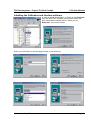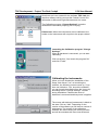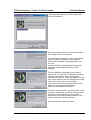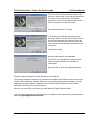
1
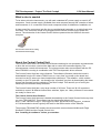
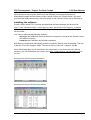
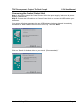
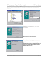
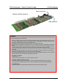
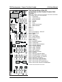
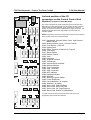
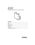
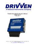
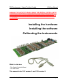
TRC Development - Project The Real Cockpit
CCU User Manual
WARNING: THE ANTI-STATIC BAG IN WHICH THE CENTRAL CONTROL UNIT IS
SHIPPED MAY NEVER BE IN CONTACT WITH ANY PARTS OF THE BOARD
WHEN THE BOARD IS CONNECTED TO THE POWER SUPPLY OR TO THE USB
CONNECTOR AND YOUR PC. THIS WILL CAUSE SHORT-CIRCUIT AND MAY
CAUSE FIRE!
Installing the hardware
Installing the software
Calibrating the instruments
What’s in the box:
- The Central Controller Board
- The USB Cable
This manual is for CCU version 1 and CCU version 2.
Version1.2 – May 2004
Page 1
TRC Development - Project The Real Cockpit
CCU User Manual
What’s else is needed
To be able to drive the instruments, you will need a standard AT power supply as used in AT
computers. Such a power supply (available from most computer stores) has a number of wires
and connectors. A.o. a connector for the main computer board, for diskdrives, harddisks, etc.
At least one of the connectors look like the one as displayed hereunder, a so-called hard drive
connector. This connector needs to be plugged into the Central Control Unit to power the
servos. The electronics of the Central Control Unit are powered via the USB from the main
computer.
The hard drive connector as coming
from the PC AT Power supply
About the Central Control Unit
The Central Control Unit is a Printed Circuit Board containing its own processor and electronics
to drive the servo motors, read out the dials and to control the instrument lighting. The
microprocessor controls all instruments. The microprocessor also communicates with the PC
where FS2002 is running in combination with TRC Development's driver software.
The Central Control Unit has unique features. The software (firmware) inside the board is
downloaded from the PC where FS2002 runs on, every time you power up the board and
connect it to the PC where you have installed the software on. The software - which resides
normally on the PC hard disk - can therefore be "refreshed" any time by downloading the latest
drivers and firmware from the website of The Real Cockpit. This assures you of having the
latest improved software always available.
The Central Control Unit has a very large number of I/O lines. There are 38 I/O connectors
available to control 38 different instruments, switches, lights, etc. Many of these I/O connectors
are ready for future use.
The Central Control Unit firmware
The Central Control Unit firmware is loaded automatically to the Central Control Unit every time
you start TRCLINK.EXE. This software can be downloaded directly from:
http://www.therealcockpit.com/support/index.php?boxaction=support_software
It is recommended to check regularly this area for the latest version of the software.
The program TRCLINK.EXE contains the drivers which communicate with Microsoft Flight
Simulator FS2002 and the Central Control Unit.
See “Installing the software” before you continue
Version1.2 – May 2004
Page 2
TRC Development - Project The Real Cockpit
CCU User Manual
Upon the start of this program (before you start FS2002), the necessary firmware is
automatically loaded into the memory of the Central Control Unit. Please check if you have
connected the USB cable properly and if the power to the Central Control Unit is switched on.
Installing the software
Create a folder called TRC Controller and download the latest software and drivers from
http://www.therealcockpit.com/support/index.php?boxaction=support_software
into this folder.
You have to download the following software:
- driver.zip (the USB driver which enables the computer to recognize the Central Control
Unit USB connection)
- setup.zip (the Calibration and Interface software)
Both files are compressed with Winzip in order to make the files as small as possible. The size
of the file “driver.zip” is approx. 50Kb. The size of the file “setup.zip” is approx. 2,6 Mb.
Once downloaded they can be extracted in the same folder. If you do not have the Winzip
extractor, you can download a trial version from http://www.winzip.com/ddchomea.htm at
no cost.
Extracting the file driver.zip into folder TRC Software
Extracting the file setup.zip into directory TRC Software
Version1.2 – May 2004
Page 3
TRC Development - Project The Real Cockpit
CCU User Manual
Connecting the Central Control Unit
Step 1: Now firstly connect the Central Control Unit to the power supply. Make sure the power
supply is switched on.
Step 2: Connect the USB cable to the Central Control Unit and connect the USB cable to your
computer.
Your screen will show a message that new USB hardware has been detected. Immediately
thereafter the “New hardware found” screen comes up. Now click Next.
Click on “Search for the best driver for your device. (Recommended).”
Version1.2 – May 2004
Page 4
TRC Development - Project The Real Cockpit
CCU User Manual
Specify a location, choose the folder TRC Controller (or the folder where you extracted the
software in)
If Windows has found the driver, your screen
should show:
Now click next to install the software.
If the software is installed properly, the screen
shows:
This concludes the installation of the USB
hardware driver. Now you are ready to install the
Calibration Software and to install the Interface
Software called TRC Link.
Version1.2 – May 2004
Page 5
TRC Development - Project The Real Cockpit
CCU User Manual
Connecting the Instruments to the Central Control Unit
Make sure the power supply is switched on, the USB cable is connected to your
computer and the firmware has been loaded onto the Central Control Unit.
When the software is properly running on the Central Control Unit, a small LED, situated
between the power connector and the USB connectors flashes every 0,5 seconds.
When the LED is not flashing, please check if the TRC Link software or the Calibration software
has been started. If these programs are not started, the firmware has not been loaded into the
Central Control Unit, which is shown by the flashing LED.
Each instrument has its own connection to the central control unit by means of a so-called flat
cable. There are 6 different size of flat cable connectors for the CCU version 1:
- 2-wire flatcable,
- 3 wire flatcable,
- 4-wire flatcable,
- 10-wire flatcable,
- 14-wire flatcable and
- 20-wire flatcable.
and 3 different size of flat cable connectors for the CCU version 2:
- 10-wire flatcable,
- 14-wire flatcable and
- 20-wire flatcable.
Each type of connector has its own notch, preventing the connector to be inserted wrongly. Due
to many connectors on the Central Control Unit having the same amount of pins, be careful not
to connect the wrong instrument to the wrong connector.
Due to the design, connecting a certain instrument onto the wrong connector will not damage
your Central Control Unit or your instrument, but the instrument may not function and other
instruments may be influenced by a wrongly connected instrument.
On the next page, you will see a drawing of the Central Control Unit, with each individual
number of each connector printed on it. On the Central Control Unit itself, you will find the
number of the connector printed on the product just on the left hand top side when you hold the
board towards you, with the connectors facing up and the power and USB connector on the
right hand side.
Caution: The Central Control Unit is a delicate electronic device. Static electricity may
damage the board. This is not covered by warranty! Please discharge yourselves before
touching the board. It is recommended to hold the board only by the edges and leave it
in the anti-static bag before using it.
WARNING: THE ANTI-STATIC BAG MAY NEVER BE IN CONTACT WITH ANY
PARTS OF THE BOARD WHEN THE BOARD IS CONNECTED TO THE POWER
SUPPLY OR TO THE USB CONNECTOR AND YOUR PC. THIS WILL CAUSE
SHORT-CIRCUIT AND MAY CAUSE FIRE!
Version1.2 – May 2004
Page 6
TRC Development - Project The Real Cockpit
CCU User Manual
Power Connector
(Picture of CCU version 1)
USB Connector
WARNING:
The Central Control Unit is a delicate piece of electronics. Please take precautions when touching the board.
It may be damaged by static electricity!
1. Leave the Central Control Unit in its protecting antistatic bag as long as possible. Never leave it in or on
top of the antistatic bag when power is connected or when the USB cable is connected. This may cause
the board to be destroyed or your PC may be damaged!
2. Discharge yourselves - before touching the board - to something grounded.
3. Avoid touching the integrated circuits and other parts mounted on the board by handling the board by the
edges.
4. The connectors attached to the instruments can only be connected one way, due to a positioning notch
on each connector on the Central Control Unit as well as on the flat cable of the instruments.
5. Connect the instruments one by one to the Central Control Unit, before connecting the power supply and
USB cable.
6. After connecting the instruments, first connect the power supply by using a standard AT Power supply
and utilizing the disk drive power connector from the AT Power Supply.
7. Watch the small LED (red indicator) on the Central Control Unit, mounted between the Power Connector
and the USB connector. This LED has the following conditions:
The LED is not lighted
- Power is off or:
- Power is connected and there is no USB connection to the PC.
The LED is steady On (does not flash)
- There is a USB connection to the computer, but the firmware (internal software for the Central
ControlUnit is not yet loaded from the PC. You have to start the driver software (TRCLINK.EXE).
The LED Flashes
- Power is connected and the firmware is loaded into the Central Control Unit memory.
Version1.2 – May 2004
Page 7
TRC Development - Project The Real Cockpit
CCU User Manual
List and position of the I/O
connectors on the Central Control Unit
Version 1
CN38
CN27
CN22
CN32
CN26
CN21
CN34
CN37
CN25
CN20
CN31
CN29
CN24
CN19
CN30
CN28
CN23
Version1.2 – May 2004
Handbrake
Avionics Switch
Quartz Counter
Throttle
Mixture
Prop
Light Control Input
Master Switch
*)
*)
*)
*)
Fuel selector + Shut off
Digital Clock
Flaps
Trim wheel
Starter Switch
Rudder Pedals
Yoke
Compass
Airspeed Indicator
Tachometer
Vertical Speed Indicator
Attitude Indicator
Turn Coordinator
VOR 1 Indicator
VOR 2 Indicator
ADF Indicator
Heading Indicator
Altimeter
Warning Lights & Switch
Autopilot Switch + Warnings
Circuit breakers (15 outputs)
Switches (16 inputs)
Servo Ctrld. Fuel Left/Right
Servo Ctrld. EGT/Fuel Flow
Servo Ctrld. Oil Temp/Pressure
Servo Ctrld. Suction G./AMindicator
CN17
CN16
CN15
CN14
CN13
CN1 CN2 CN3
CN6
CN7
CN8
CN9
CN10
CN11
CN12
CN43
CN18
CN33
CN36
*) These connections have no function.
CN35
CN5
CN1
CN2
CN3
CN4
CN5
CN6
CN7
CN8
CN9
CN10
CN11
CN12
CN13
CN14
CN15
CN16
CN17
CN18
CN19
CN20
CN21
CN22
CN23
CN24
CN25
CN26
CN27
CN28
CN29
CN30
CN31
CN32
CN33
CN34
CN35
CN36
CN37
CN38
CN4
NOTE: The position of the text on the picture on the left is not identical
to the position of the text on the board itself.
Page 8
TRC Development - Project The Real Cockpit
CCU User Manual
CN38
CN37
CN36
CN35
List and position of the I/O
connectors on the Central Control Unit
Version 2 (shipped as from May 2004)
The CCU2 is prepared for future expansion with more I/O lines and
will be able to control instruments for a twin engine aircraft. Therefore
more I/O lines are made available. At the same time a number of
smaller connectors have been combined into 2 larger connectors. The
additional I/O lines will become supported in the near future via
software updates.
CN27
CN22
CN34
CN26
CN21
CN32
CN25
CN20
CN31
CN29
CN24
CN19
CN30
CN28
CN23
CN11 Handbrake, Avionics Switch, Gear, Light Control,
Master Switch
CN12 Analog outputs, 8 pcs.*), Quartz Counter
CN13 Fuel selector + Shut off
CN14 Digital Clock
CN15 Flaps, Throttle1/2, Mixture1/2, Prop1/2
CN16 Trim wheel
CN17 Starter Switch
CN18 Rudder Pedals
CN19 Yoke
CN20 Compass
CN21 Airspeed Indicator
CN22 Tachometer
CN23 Vertical Speed Indicator
CN24 Attitude Indicator
CN25 Turn Coordinator
CN26 VOR 1 Indicator
CN27 VOR 2 Indicator
CN28 ADF Indicator
CN29 Heading Indicator
CN30 Altimeter
CN31 Warning Lights & Switch
CN32 Future Expansion
CN33 Circuit breakers (15 outputs)
CN34 Switches (16 inputs)
CN35 Servo Ctrld. Fuel Left/Right
CN36 Servo Ctrld. EGT/Fuel Flow
CN37 Servo Ctrld. Oil Temp/Pressure
CN38 Servo Ctrld. Suction G./AMindicator
*) These connections are for future expansion and are not yet
supported by the firmware and software.
Version1.2 – May 2004
CN17
CN16
CN15
CN14
CN13
CN11
CN1 CN2 CN3
CN4
CN5
CN6
CN7
CN8
CN9
CN10
CN12
CN11
CN12
CN43
CN18
CN33
NOTE: The position of the text on the picture on the left is not identical
to the position of the text on the board itself.
Page 9
TRC Development - Project The Real Cockpit
CCU User Manual
Installing the Calibration and Interface software
In order to install the software, you have to run Setup.exe
from the folder TRC Software (or the folder where you
have extracted the zipped files in). When you run
Setup.exe, your screen shows:
Enter your information in the following screens or just click next.
Version1.2 – May 2004
Page 10
TRC Development - Project The Real Cockpit
CCU User Manual
Now there are icons created for the software TRC Link (the
interface software which connects the Central Control Unit
information to Microsoft Flight Simulator and vice versa.
The Calibration program “Change Settings” is used to
calibrate all instruments properly, prior to “flying”.
Please note: When the instruments are not calibrated, the
hands on the instruments will not point to the proper values!
Launching the Calibration program “Change
Settings”
When all hardware is connected, you can start
calibrating.
Click on the box “Yes, launch the program file”
and click “Finish”.
Calibrating the instruments
When you have finished the installation of the
Setup, and clicked “Yes” on launching the
software, the following screen comes up. If you
have not clicked on “Yes, launch the software”,
you can launch the software from the Icon or by
launching the file “Change Settings”, created
during installation. Please make sure all
hardware is connected and that power is applied.
The screen with devices (instruments) is blank at
the start. Click on “Add”. Depending on the
version of the software you will have a number of
instruments. The version of the calibration
software will mature during the coming months
and will be extended with more instruments as
Version1.2 – May 2004
Page 11
TRC Development - Project The Real Cockpit
CCU User Manual
they become available. Therefore it is recommended to check regularly for the latest version of
the Calibration software at
http://www.therealcockpit.com/support/index.php?boxaction=support_software
When you have clicked on “Add”, the screen as
shown on the left will show up.
Depending on which instrument you have
installed onto the Central Control Unit, just click
the check box near the instrument.
After clicking one ore more check boxes, click
“OK”.
You have selected the instruments which will be
controlled by the Central Control Unit.
Now select the instrument you would like to
calibrate by clicking on it.
You can use the calibration program later any
time over and over again when you are not
satisfied with the calibration. However normally,
you should do this only once for each instrument.
Version1.2 – May 2004
Page 12
TRC Development - Project The Real Cockpit
CCU User Manual
When you have selected a certain instrument,
click on “Calibrate”
Click Next on this screen if you have connected
the Central Control Unit properly.
You will notice a message on the screen saying
that the firmware (software) for the Central
Control Unit is loaded via the US|B cable onto
the unit.
A small red LED, situated between the power
connector and the USB connector is now
flashing.
For the calibration, depending on the type of
instrument, you will have to calibrate on multiple
settings of the hand or other moving parts.
This is the first screen. Move the slider or use the
left or right arrows on the left and right side of the
slider to move the hand on the original
instrument until it has the same position as the
hand on the picture of the instrument.
When you are satisfied, click Next.
This is the second screen, move the slider or use
the left or right arrows on the left and right side of
the slider to move the hand on the original
instrument until it has the same position as the
hand on the picture of the instrument.
Now click Next for calibration step 3.
Version1.2 – May 2004
Page 13
TRC Development - Project The Real Cockpit
CCU User Manual
This is the third screen. Move the slider or use
the left or right arrows on the left and right side of
the slider to move the hand on the original
instrument until it has the same position as the
hand on the picture of the instrument.
Now click Next for the 4th screen.
This is the fourth and last calibration screen.
Move the slider or use the left or right arrows on
the left and right side of the slider to move the
hand on the original instrument until it has the
same position as the hand on the picture of the
instrument.
Click Next to finish.
Now the instrument is fully calibrated.
Click Finish, and add another instrument and
follow the same procedure to calibrate all
instruments.
Now click OK, to save the calibrated settings.
Follow the same procedure for each instrument until finished.
The present Calibration software only contains the available instruments at the moment of the
release of the Calibration software. Each time a new instrument becomes available, you can
download the latest calibration software from The Real Cockpit Website, which contains
calibration screens for the new instruments.
Now you can start TRC Link, before you start Microsoft Flight Simulator 2002.
I you have any questions concerning the use or calibration of the instruments, please send an
email to [email protected].
Version1.2 – May 2004
Page 14
TRC Development - Project The Real Cockpit
CCU User Manual
The Real Cockpit is a product of
Company Address:
TRC Development b.v.
Stationsweg 39
4241 XH ARKEL
THE NETHERLANDS
Postal Address:
TRC Development b.v.
P.O.Box 544
4200 AM GORINCHEM
THE NETHERLANDS
All Products carry a limited warranty of 12 months after purchase.
Please look for warrant text on our website: www.therealcockpit.com
All information requests and support requests can be directed to:
[email protected]
Our office hours are:
Monday till Friday 09:00AM till 05:00PM (09:00-17:00) Central European Time.
(03:00AM – 02:00PM Eastern Time)
Phone: (from USA): 011 31 183 562 522, (from Europe): 0031 183 562 522
Fax: (from USA): 011 31 183 564 268, (from Europe): 0031 183 564 268
Shipping
Our main shipper is UPS. We ship all our products UPS Express.
For non-urgent shipments we use TPG (first class mail)
Order taking
We accept most credit cards. When ordering products, your credit card is only charged at the
day of shipping. Our secure credit card handling over the internet is done by Bibit
(www.bibit.com).
Privacy Statement
TRC Development will never use your email address for any other purpose than informing you
about new products or other breaking news on The Real Cockpit products or software.
When you do not wish to receive information by email, you can remove yourself from the
mailing list at any time. Please see: www.therealcockpit.com.
Returning goods for repair or replace
Whenever you would like to return a product for repair or replace (at the choice of TRC
Development b.v.) you will need a so-called RMA Number. RMA Numbers can be requested
by email or by fax.
See our website support area for details on how to return a product. There you find a form
which – when information is entered – will supply you with the proper RMA number:
http://www.therealcockpit.com/support/index.php?boxaction=support_return
Version1.2 – May 2004
Page 15