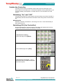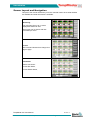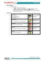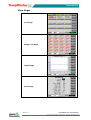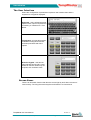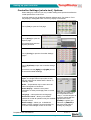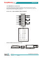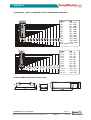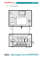
1
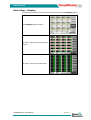
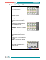
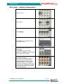
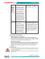
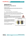
User Manual
for M1 Series
of Hot Runner Controller
TempMaster M1 User Manual
KEEP THIS SHEET SOMEWHERE SAFE
Every machine leaves our factory with two levels of
password protection. We recommend that you remove this
sheet in order to establish your own security.
User Password - unix
System Password - linux
TempMaster M1 User Manual
TempMaster M1 User Manual
TempMaster M1 User Manual
Amendment Record
Issue
Date
Amendments
Author
Authorised
0.0
Oct 2011
Approval Issue
DH
SK & IE
1.0
Jan 2012
First issue
DH
SK
Copyright © 2011 Mold-Masters® Developments
This manual is intended for use with the M1 Series Controller
Our policy is one of continuous improvement and we reserve the right to alter
product specifications at any time without giving notice.
TempMaster M1 User Manual
Not Under documentation control if printed. May be revised without notice.
Revision 1.0
Page 1
©Jan 2012
TempMaster M1 User Manual
Contents
TempMaster M1 User Manual......................................................................... 1 Introduction ..................................................................................................... 3 Setting up your controller ...............................................................................14 Running your controller ..................................................................................26 Customising your controller ...........................................................................35 Maintaining your controller .............................................................................42 Troubleshooting .............................................................................................47 Appendix A ....................................................................................................50 Global Support ...............................................................................................56 TempMaster M1 User Manual
Revision 1.0
© Jan 2012
Page 2
Not Under documentation control if printed. May be revised without notice.
Introduction
Introduction
Specifications
The following are general specifications. The actual controller supplied may differ in
specified options.
Supply Voltage
85-265Vac 3 phase 50Hz with neutral, others
available for 220/60Hz Delta
Unit Overload protection
Miniature Circuit Breaker
Output overload protection
15A super-quick acting (FF) fuse on both legs
Power output
15A/3600W per zone
Ground Fault Detection
20mA per zone
Thermocouple input
type 'J', or type ‘K’
Control Method
Self tuning PID
Soft-Start with Auto Tune
Unique low voltage method for heater safety
Temperature scale
Centigrade (Celsius) or Fahrenheit
Operating Range
0 - 472°C or 32 - 882°F
Control Accuracy
+/-1°C
Alarm Output
Closing volt-free contacts - 5A max 230V
Remote Input
Voltage free pair to signal Boost or Standby
Interface
5.7” Full colour LCD touch screen
Case Details
Heavy duty metal cabinet with swing up console
Size: M1-xx-48: 350w x 510d x 500h (mm)
Size: M1-xx-12: 350w x 510 d x 220 h (mm)
TempMaster M1 User Manual
Not Under documentation control if printed. May be revised without notice.
Revision 1.0
Page 3
©Jan 2012
Introduction
Safety Instructions
DO NOT open the cabinet without first ISOLATING the supplies - there are
unguarded terminals inside the cabinet which may have a dangerous potential
across them.
Where a three-phase supply is used then this potential may be at 415 volts or
higher.
Safety Notices - an explanation
A WARNING symbol and message, shown here, identifies where there may be a
hazardous situation which, if not avoided, may result in death or injury to personnel.
Most warnings pertain to electrical aspects and you must comply with them to
minimise any personal danger.
A CAUTION warning identifies where there may be a hazardous situation which, if
not avoided, may result in damage to property.
Caution warnings present no personal danger, but may cause the equipment to fail
or lose its memory.
Where to use this equipment
The display console and controller cabinet together are designed for use in the
plastic injection moulding industry as temperature controllers for third party hot
runner systems as commonly used in mould tools. They must not be used in
residential, commercial or light-industrial environments. Furthermore, they must not
be used in an explosive atmosphere, or where there is a possibility of such an
atmosphere developing.
The HRC cabinet and Touch Screen console should be installed in a clean dry
environment where the ambient conditions do not exceed the following limits: •
•
Temperature
Relative Humidity
0 to +35°C.
90% (non-condensing)
Check your wiring
Before you energise the system, pay special attention to how the supply to your
controller is wired and how it is connected to the mould.
Lack of attention to detail causes errors such as:
•
•
incorrect wiring of mains supply phases into the controller
crossing heater supply feeds with thermocouple detection (although this error
can be eliminated by the adoption of Mold-Masters Standard connections)
In such cases wiring errors have caused equipment failure.
Mold-Masters (UK) Ltd. cannot be responsible for damage caused to the controller
by customer wiring and/or connection errors.
TempMaster M1 User Manual
Revision 1.0
© Jan 2012
Page 4
Not Under documentation control if printed. May be revised without notice.
Introduction
The Controller Cabinet
The power supply to the control cabinet is via a strain-relief mounted cable gland
plug and this may be wired in star or delta configuration. (Please check your
specifications for details of which configuration has been configured.) There are
normally two types of cables supplied; a thermocouple connection, and a power
connection, both using type HAN24E as a preferred connector.
Typical wiring details are shown in Appendix A.
An alarm output option is available for extending the alarm, or, perhaps, inhibiting
the injection process.
Controller Modules
The controller uses six-zone modules that provide real time temperature control.
Each card has three main components:
•
•
•
thermocouple input CPU,
two control CPUs,
multi-voltage output triacs.
Thermocouple Inputs
The thermocouple inputs have preset responses for both J and K- type
thermocouples. The associated console provides means of selecting the sensor
type which, in turn, sets the CPU linearization to match the selected thermocouple
type.
Central Processor Units (CPUs)
The CPU provides the following facilities:
•
•
•
•
closed and open loop control of the zones,
processes thermocouple and current readings to show on display,
checks for alarm conditions, including excess current, incorrect
thermocouple wiring, zone over temperature condition, low impedance
between heater and ground, and generates alarm information for the display
screen and alarm relay,
controls the output power to the on-board triac using a number of self-tuning
algorithms
The card requires no analogue calibration and is ready for use once set up from the
display console.
Output Triacs
The controller card has six on-board triacs, one for each channel, that are capable
of controlling heating loads of up to 15 Amps peak.
Power Supply
The D.C. power supplies for the cards, data communications and an alarm output
relay are all provided by a single Power Supply Unit. This is located on top of the
upper chassis panel.
TempMaster M1 User Manual
Not Under documentation control if printed. May be revised without notice.
Revision 1.0
Page 5
©Jan 2012
Introduction
Isolate the Controller
The main Power Switch is sufficiently rated to disconnect the total load current
during switch On and switch Off. To prevent its operation, during maintenance, you
can use a suitably- sized padlock, or similar device, to lock the switch in the Off
position.
Switching "On" and "Off"
The main power switch is a rotary switch found at the lower rear of the Controller. It
is sufficiently rated to disconnect the total load current during switch On and switch
Off.
Switching On
When the controller is switched on, all zones go into “Run” mode automatically to
start heating the tool.
Switching Off (the Controller)
We recommend that you use the console to shut down the heating load, and only
use the main isolator to switch off a dormant controller.
1. Shut down the heating.
On the main page, touch [Mode].
2. On the Mode page touch [Stop]
3. Shut down the Controller - use the
main power switch to isolate all the power
to the whole system.
TempMaster M1 User Manual
Revision 1.0
© Jan 2012
Page 6
Not Under documentation control if printed. May be revised without notice.
Introduction
Screen Layout and Navigation
This part of the manual introduces you to the controller card to show what facilities
are available and what information is available.
Monitoring
The main page has up to 12 zones
displayed at maximum size.
More zones can be shown with less
information per zone..
Control
Side command buttons that change from
page to page.
Information
Bottom row shows :
Current Run Mode,
Current Health Status,
TempMaster M1 User Manual
Not Under documentation control if printed. May be revised without notice.
Revision 1.0
Page 7
©Jan 2012
Introduction
Main Page
Can be used for
•
•
•
Monitor – observe zone condition
Control – Start/Stop & Boost/Standby immediately available. All other
(“Standby, Shutdown, Stop“) available from [Mode] button
Set – select any one or more zones to get [Set] function to set or alter zone
set-points or run modes.
Monitoring
Healthy Zone - shows:
Zone Name
Actual Temperature
Scale + Set Temperature
Applied Power
Green text on Black
background
Warning Zone
Black Text on
Yellow Background
Deviation exceeds 50% of Alarm Setpoint
Alarm Zone
White text on Red
Background
Deviation exceeds Alarm Setpoint
Fatal Error
Problem detected (see page 47 for details)
White text on Red
Background
Zone Off
Individual zone switched off
TempMaster M1 User Manual
Revision 1.0
© Jan 2012
Page 8
Not Under documentation control if printed. May be revised without notice.
Introduction
Main Page – Display
To show less information and more zones (24-48 zones) use the [Display] button.
Use [Display] button to show…
24 Zones - each zone shows Title and
Actual
48 Zones - each zone shows Actual
TempMaster M1 User Manual
Not Under documentation control if printed. May be revised without notice.
Revision 1.0
Page 9
©Jan 2012
Introduction
Control – Start Stop and More
Touch [Mode] on the top right brings a new
set of command buttons.
The next page offers four modes that are
immediately available.
RUN – raise all the zones to their set
operating temperature
STANDBY - Any zones with Standby
Temperatures configured are reduced in
temperature until the next command is
given.
START – The system is started in a
homogenous heat-rise in which all zones
follow the slowest rising zone.
It will switch to RUN when working
temperature has been reached.
SHUTDOWN – The system is shut down in
a homogenous heat reduction. It will switch
to STOP when temperatures are less than
90°C.
BOOST – Any zones with Boost
Temperatures configured are temporarily
increased for a user-configurable period.
When the boost period expires then zone
temperatures return to their normal Set
levels.
STOP – set all power levels to zero and lets
the tool cool down to room temperature at
its own rate.
CANCEL – returns you to the main page
Secondary conformation is required to go
into any mode other than that which is
currently being used.
TempMaster M1 User Manual
Revision 1.0
© Jan 2012
Page 10
Not Under documentation control if printed. May be revised without notice.
Introduction
Main Page – Setting Temperature
Touch one zone
Touch another
Touch [Range]
Touch [Set], and, if prompted, enter
the User Password.
Use the key pad to “type” a new
Temperature.
Touch [Ent] to set the required
temperature or [Bsp] to leave the page
without making any changes.
On return to main page, you see the
new set temperatures
Note: they may individually show an
Alarm if the new set temperature is
significantly different to the present
actual temperature – but the system
sees this as a temporary condition and
will not show an overall Alarm condition
until the tool has had time to attain the
new set temperatures.
TempMaster M1 User Manual
Not Under documentation control if printed. May be revised without notice.
Revision 1.0
Page 11
©Jan 2012
Introduction
More Pages
Tool Page
Setup Tool Page
Graph Page
Zoom Page
TempMaster M1 User Manual
Revision 1.0
© Jan 2012
Page 12
Not Under documentation control if printed. May be revised without notice.
Introduction
The User Interface
Where the configuration of parameters requires a user interface then either a
keyboard or a keypad is displayed.
Keyboard – this is offered wherever
alpha-numeric input is required such
as entering a Password or a Tool
Name.
Full Keypad – this has all functions
available including Boost and Off
switches plus Mode and Value
options
Numeric Keypad – this has left
hand side greyed out and is used
wherever numeric values only are
required, such as Alarm Limits.
Screen Saver
There is an automatic function that dims the screen light by 50% after 5 minutes of
user inactivity. Touching the screen anywhere will restore it to normal level.
TempMaster M1 User Manual
Not Under documentation control if printed. May be revised without notice.
Revision 1.0
Page 13
©Jan 2012
Setting up your controller
Setting up your controller
New M1 series controllers leave the factory with their default settings as shown in
this table below.
Zone Temperature
0 ºC or 0ºF
Standby level
65ºC or 118ºF
Boost level
0ºC or 0ºF
Over temperature range
10ºC or 18ºF
Under temperature range
Maximum Power
85%
If you are reconfiguring your controller to a new tool or environment then this
chapter of the manual shows how to alter the various parameters to your preferred
values and afterwards to save them.
What is covered in this section
Controller Settings – settings that apply to the whole tool
Zone settings – settings that apply to one or more zones
Limits – upper and lower alarm limits
Boost – the temperature increase when Boost Mode is selected
Standby – the temperature reduction when Standby Mode is selected
TempMaster M1 User Manual
Revision 1.0
© Jan 2012
Page 14
Not Under documentation control if printed. May be revised without notice.
Setting up your controller
Controller Settings (whole-tool) Options
When setting up a new tool you may consider setting these options that affect the
overall performance of each tool.
Controller settings may be different between different tools. For instance Tool 1
may display in Centigrade while Tool 2 may display in Fahrenheit
Touch [Tool] to open the Tool page
Touch [Setup] to open the
Options page.
If prompted then enter the
System password.
Touch [Config] to open the Controller Settings
pages.
Touch [Options] to open the Controller settings
pages.
(once there use the [PgUp] and [PgDn] buttons
to view all Controller Settings)
Settings on these pages include…
Input – the single channel input (HA4 socket)
may be configured to initiate either a “Boost” or
“Standby” mode
Scale – Temperatures may be set to show as
either Centigrade or Fahrenheit
Power Display – select the zone panel
information to show percentage power or actual
current
Language – select preferred user language
Password Control – allows you to disable
passwords so that all operations may be available
for open control
Earth Leakage – allows you to disable the
display of Earth Leakage current and switch on,
or off, the earth leakage control on the card.
To select any option, such
as Temperature scale is
“Deg C”, touch that option to
move the yellow selection
indicator then touch
[Enter] to confirm your
selection or [Cancel] to
leave the page without
making any changes.
TempMaster M1 User Manual
Not Under documentation control if printed. May be revised without notice.
Revision 1.0
Page 15
©Jan 2012
Setting up your controller
Global Settings (Tool Options)
When setting up a new tool you may consider setting these options that affect the
overall performance of each tool.
Controller settings may be different between different tools. For instance Tool 1
may display in Centigrade while Tool 2 may display in Fahrenheit
Touch [Tool] to open the Tool page
Touch [Setup] to open the
Options page.
If prompted then enter the
System password.
Touch [Config] to open the Controller Settings
pages.
Touch [Global] to open the Global settings
panel.
Settings within this panel include…
Boost Time - to enter the time for which the
temperature will increase whenever the Boost
mode is selected. (Note: Maximum Permissible
Boost time is 500 seconds.)
Maximum Temperature – to limit the highest
temperature to which any zone may be
raised.(Note: the highest permitted Maximum
Temp is 472° C or 880°F)
Maximum Power – to limit the highest power to
which any zone may be raised. (Note: the highest
permitted Maximum Power is 100%)
Touch [Edit] to set any parameter or [Back] to
close the panel and leave without making any
changes.
TempMaster M1 User Manual
Revision 1.0
© Jan 2012
Page 16
Not Under documentation control if printed. May be revised without notice.
Setting up your controller
Zone Settings
When setting up a new tool you may consider setting these options that are
applicable on a zone by zone basis for any tool.
Zone settings may be different between different tools. For instance Tool 1 may
have manifold speeds set to manual slow while Tool 2 may have all zones speeds
in Automatic.
Touch [Tool] to open the Tool page
Touch [Setup] to open the
Options page.
If prompted then enter the
System password.
Touch one or more zones to see new command
buttons.
Touch [Set] to view the next page
Touch [Options] to open the Zone Settings pages.
(once there, use the [PgUp] and [PgDn] buttons
to view all Controller Settings)
Settings on these pages include…
Alias – uses the selected a title to identify a group
of zones as either Probes, Manifolds or Sprues. “Not
Used” allows you to switch off spare zones so they
do not show on the main page.
Speed – allows you to leave zones at Auto-detect
setting or over-ride to slow, medium or fast should
the auto setting not giving the best performance
Sensor – allows you to match the controller to either
J-Type or K-type thermocouple.
Touch [Cancel] to step back and return to main
page.
TempMaster M1 User Manual
Not Under documentation control if printed. May be revised without notice.
To select any option, such as
Alias as “Probe”, touch that
option to move the yellow
selection indicator, and then
touch [Enter] to confirm your
selection or [Cancel] to leave
the page without making any
changes.
Revision 1.0
Page 17
©Jan 2012
Setting up your controller
Monitoring Temperature Limits
Your controller card monitors the actual temperature of each zone and verifies that
the zone is operating within specific limits. Rather than fixed points of temperature,
the High and Low Limits are set as deviation above or below the set point. If any
zone temperature goes outside these limits, a visual alarm is shown which is
extended to an alarm relay for external switching.
Warn and Alarm limits
Although there is only one upper and one lower Alarm setting, each gives a visual
warning at half way point. If a High alarm is set to 10 deg then a Warning will show
at 5 deg. The same is applicable for the under temp alarm level.
Touch [Tool] to open the Tool page
Touch [Setup] to open the
Options page.
If prompted then enter the
System password.
Select one or more zones – either
Select one zone then another, then another, till you
have all the required zones
– Or –
Select the first zone, then the last, then touch
[Range] to include all in between
Touch [Set] to show the zone setting options.
Touch [Limits] to open Alarm Limits panel.
Within the Alarm Limits panel touch either High or
Low [Edit] to reveal a keypad. The keypad allows
you to enter the amount by which temperature must
rise or fall to trigger an upper or lower temperature
alarm.
Note that temperature limits are applicable to the
current scale. A High limit of “10” while in
Centigrade would automatically become “18” when
you change the scale to Fahrenheit.
Touch [Cancel] to step back and return to main
page.
TempMaster M1 User Manual
Revision 1.0
© Jan 2012
Page 18
Not Under documentation control if printed. May be revised without notice.
Setting up your controller
Setting Boost Temperature
The Boost Temperature may be individually set for each zone as described in the table below.
When boost is activated, the controller will raise the zone temperature. Please note that,
on a slow responding manifold, if you set a high boost temperature, the zone may not
reach the set boost temperature before the boost time limit expires.
The Boost period is user-configurable and setting this is detailed on the following page.
Touch [Tool] to open the Tool page
Touch [Setup] to open the
Options page.
If prompted then enter the
System password.
Select one or more zones – either
Select all the required zones
– Or –
Select the first zone, then the last, then touch
[Range] to include all in between
Touch [Set] to show the zone setting options
Touch [Boost].
Within the Boost panel, touch [Edit] to reveal a
keypad. The keypad allows you to enter the
amount by which the temperature will increase
whenever the Boost mode is selected.
Note: Maximum Permissible Boost temperature
is 100° C or 180° F
Touch [Cancel] to step back and return to
main page.
TempMaster M1 User Manual
Not Under documentation control if printed. May be revised without notice.
Revision 1.0
Page 19
©Jan 2012
Setting up your controller
Setting Standby Value
Before you activate Standby function, you must first configure the amount. The
Standby settings made here are only for Standby Temperature and are individually
set for each zone. When standby is activated, those zones with any standby value
configured will reduce their temperature.
Touch [Tool] to open the Tool page
Touch [Setup] to open the
Options page.
If prompted then enter the
System password.
Select one or more zones – either
Select one zone then another, then another,
till you have all the required zones
– Or –
Select the first zone, then the last, and then
touch [Range] to include all in between.
Touch [Set] to show the zone setting options
Touch [Standby] to open the Standby panel.
Within the Standby panel, touch [Edit] to
reveal a keypad.
The keypad allows you to enter the amount by
which the temperature will reduce whenever
the Boost mode is selected.
Note: Maximum Permissible Standby
temperature is 100° C or 180° F.
Touch [Cancel] to step back and return to
main page.
TempMaster M1 User Manual
Revision 1.0
© Jan 2012
Page 20
Not Under documentation control if printed. May be revised without notice.
Setting up your controller
Set Zone Temperatures and save to Tool Bank
Touch one zone
Touch another
Touch [Range]
Touch [Set], and, if
prompted, enter the System
Password.
Use the key pad to select a new
Temperature.
Touch [Ent] to set the required
temperature or [Esc] to leave the page
without making any changes.
Note: Maximum Permissible
temperature is 472° C or 882° F
On return to main page you see new
set temperatures (here shown in
Warning because they are currently
higher than actual temperature)
TempMaster M1 User Manual
Not Under documentation control if printed. May be revised without notice.
Revision 1.0
Page 21
©Jan 2012
Setting up your controller
Save new Tool to Tool Bank
(From previous page)
Touch [Tool] to open the Tool Page
Touch any blank tool slot then touch [New]
Enter Tool Name and Touch the [Enter] button
Note: Maximum Permissible tool name is 12
characters long.
Touch [Load] and [OK] to accept new toolbank.
Return to Tool page to see new tool with new
name.
Touch [Back] to return to main page with new
tool saved.
TempMaster M1 User Manual
Revision 1.0
© Jan 2012
Page 22
Not Under documentation control if printed. May be revised without notice.
Setting up your controller
Password Options
When you first use your Touch Screen controller you find, as you go through the
screens, that some functions are protected by password access. Wherever a
password is required then a keyboard is displayed where you can enter the
required password.
Three levels of control
If the User Password option is set to [Enabled] then there are three levels of
control…
1) Open Level - includes various functions that need no password such as Start
and Stop.
2) User is a Level 1 password which gives low level access to:
•
•
•
switch the tool on and off,
alter temperatures,
select different tools
3) System is a Level 2 password which gives high-level access to:
•
•
•
all user-level functions,
re-configure the settings for a new tool,
store and load new tool settings to/from a memory stick
Password Disabled
If the Password option is set to [Disabled] then all both User and System functions
become Open Level and no longer require any Password to access.
About password active times
After you key in a password, access is possible while you continue to input data.
Each key-touch resets the timer but, when no more input is detected, it times out
and then denies unauthorised access.
TempMaster M1 User Manual
Not Under documentation control if printed. May be revised without notice.
Revision 1.0
Page 23
©Jan 2012
Setting up your controller
Setting Password Control
Touch [Tool]
Touch [Setup]
Enter password (if enabled)
Touch [Config]
Touch [Options]
Touch [PgDn] (twice) to see “Password
Control”
Select [Enable] to have a higher level
password control or [Disable] for “open”
control.
Touch [Enter] to accept the setting or
[Cancel] to step back and return to main page.
TempMaster M1 User Manual
Revision 1.0
© Jan 2012
Page 24
Not Under documentation control if printed. May be revised without notice.
Setting up your controller
Password Application Table
Here is a detailed list of what level of password is required for various functions on
the different pages.
Page/Screen
Main
No Password
required to
Run/Stop/Change
Modes.
Level1 (User)
password required
to:
Level 2 (System)
password required
to:
Set (Alter temperatures
or modes)
Change Display options.
Go to Zoom or Graph
page
Zoom
View only - so no other
function except zone up
or down
Graph
View only - so no other
function except zone up
or down
Tools
View available tools
Load, Save, Backup
Restore, Delete
New (Create new tools)
Tools - Setup
Set, Config (Change any
values)
Password Security
Every machine leaves our factory with two levels of password protection (these are
provided on a detachable page at the front of the Manual). We recommend that
you change these, as soon as possible, to establish your own security.
TempMaster M1 User Manual
Not Under documentation control if printed. May be revised without notice.
Revision 1.0
Page 25
©Jan 2012
Running your controller
Running your controller
‘Running your controller’ is concerned with everyday use of the controller for normal
production use. This is considered as selecting an appropriate run mode for the
machine according to whether the tool is working or waiting. It may also be
necessary to make changes to the heater temperatures and using the graphical
display of recent performance, may help such decisions.
What is included in this section
Run Modes
Manual Mode (open loop control)
Slave Mode
Standby Mode
Boost Mode – how to apply a short increase
Changing Set Temperature
Alarms
TempMaster M1 User Manual
Revision 1.0
© Jan 2012
Page 26
Not Under documentation control if printed. May be revised without notice.
Running your controller
Operating Modes (Start, Stop, Boost and more)
Touch [Mode] on the top right brings a new set
of command buttons.
RUN – raise all the zones to their set operating
temperature
STANDBY - Any zones with Standby
Temperatures configured are reduced in
temperature until the next command is given.
START – The system is started in a
homogenous heat-rise in which all zones follow
the slowest rising zone.
It will switch to RUN when working temperature
has been reached.
SHUTDOWN – The system is shut down in a
homogenous heat reduction. It will switch to
STOP when temperatures are less than 90°C.
BOOST – Any zones with Boost Temperatures
configured are temporarily increased for a userconfigurable period.
When the boost period expires then zone
temperatures return to their normal Set levels.
STOP – set all power levels to zero and lets the
tool cool down to room temperature at its own
rate.
CANCEL – returns you to the main page
Secondary conformation is required to go into
any mode other than that which is currently
being used.
More about Startup and Shutdown
STARTUP – the system measures the heat gain of every zone and automatically holds
back the faster (probe) zones to the same rise rate as the slowest rising zone. This
ensures that you get a homogenous rise across the whole tool.
SHUTDOWN – the system operates in a similar but reverse method to startup. It
switches off the slowest zone and sets the set temperature of all others to be 30°
lower. This ensures that you get a smooth uniform cool down across the whole tool.
TempMaster M1 User Manual
Not Under documentation control if printed. May be revised without notice.
Revision 1.0
Page 27
©Jan 2012
Running your controller
Boost Mode – Individual zones
This mode provides a means of temporarily boosting the zone temperature for any
one or more zones for a preset (user-configurable) period.
Touch any one or more zones
Touch [Set] and enter
password…
… to show the keypad
Touch [Boost] to raise the set level of this
selected zones
The screen reverts to main display where
you can see the boosted temperature. The
zone returns to normal temperature after
the preset Boost Time.
TempMaster M1 User Manual
Revision 1.0
© Jan 2012
Page 28
Not Under documentation control if printed. May be revised without notice.
Running your controller
Switching individual zones off
Touch any one or more zones
Touch [Set] and enter
password…
… to show the keypad
Touch [Off] to switch off the selected zones
The screen reverts to main display where you
can see the selected zone switched off.
If you select the same zone and touch [Set]
the keypad will display “On” instead of “Off” in
order to revert the zone to normal duty
TempMaster M1 User Manual
Not Under documentation control if printed. May be revised without notice.
Revision 1.0
Page 29
©Jan 2012
Running your controller
Changing or Setting Zone Temperatures
Touch one zone
Touch another
Touch [Range]
Touch [Set] and enter
password.
(Note: temperature and
power settings have a
preset limits as
described on page 16.)
To Set a new temperature - touch
[Set]
-orto Raise the overall temperature touch [Add].
-orto Lower the overall temperature touch [Sub].
and enter a value.
On return to main page, you see the
new set temperatures.
Note: they may individually show an
Alarm if the new set temperature is
significantly different to the present
actual temperature – but the system
sees this as a temporary spurious
condition and will not show an overall
Alarm condition until the tool has had
time to attain the new set temperatures.
TempMaster M1 User Manual
Revision 1.0
© Jan 2012
Page 30
Not Under documentation control if printed. May be revised without notice.
Running your controller
Changing to Manual Mode
Manual mode (open loop working) can be simply selected as an alternative to
running in Auto (closed loop).
Touch one zone
Touch another
Touch [Range]
Touch [Set] and enter
password
Touch [Man]
Key in manual percentage.
Touch [Ent].
TempMaster M1 User Manual
Not Under documentation control if printed. May be revised without notice.
Revision 1.0
Page 31
©Jan 2012
Running your controller
Slave Mode
Slave mode is an alternative to Manual and can be selected if one zone has a faulty
thermocouple. The Slaved zone then mimics the same power output as the healthy
zone and, provided that they had been running at a similar power level previously,
then the slaved zone will hold a similar temperature.
Touch any zone and see new command
buttons
Touch [Set] and enter
password
Touch [Slave]
Key in the number of a healthy zone
Touch [Ent]
Return to Main page and see first zone now
slaved to second selected zone. The Slaved
zone now displays the number of the zone that
it has been slaved to.
TempMaster M1 User Manual
Revision 1.0
© Jan 2012
Page 32
Not Under documentation control if printed. May be revised without notice.
Running your controller
Alarms
Whichever page may be active; there is a common Mode and Status window at the
bottom of the page.
If your controller is switched on and running normally then the left hand Mode
window will show RUN and the opposite Status window will show NORMAL.
Mode Window
If the controller is manually switched out of RUN mode then the Mode window
shows the selected function, and is seen flashing, on and off.
The table below lists the different displays:
RUN
Black text in
White box
All control zones are working normally
STOP
White text
in Blue box
The System has been shut down and the
heaters are at room temperature.
STANDBY
Any zones with Standby Temperatures
configured have been reduced in temperature
until the next command is given.
STARTUP
The system has been started in a
homogenous or staged heat-rise. It will
switch to RUN when working temperature has
been reached.
Yellow text
in Black box
The system has been shut down in a
homogenous or staged heat fall. It will switch
to STOP when room temperature has been
reached.
SHUTDOWN
BOOST
Black text in
Yellow box
Any zones with Boost Temperatures
configured are being temporarily raised.
(manual request)
Status Window
The right hand Status window shows NORMAL if all the zones are at their set
temperature and no faults have been detected. If any zone detects a fault then the
Status window changes its display and colour as detailed below:
NORMAL
Green text in
Black box
Controller is running normally
WARNING
Black text in
Yellow box
A zone's Temperature exceeds the warning
limits
ALARM
White text in
Red box
This shows either a Fatal Error or a zone's
temperature exceeds alarm limits
Note that the status alarm is only active when in Run Mode – so systems, whose
temperature rises slowly such as a Master-follow, will not raise spurious alarms.
Once they switch over to Run mode at their set temperature then the alarm
becomes active.
TempMaster M1 User Manual
Not Under documentation control if printed. May be revised without notice.
Revision 1.0
Page 33
©Jan 2012
Running your controller
Identifying Zone alarms
Normal Zone
Green text on
Black background
This shows a healthy zone
Black Text on
Yellow
Background
Warning Zone
This shows a first stage warning
Alarm Zone
White text on Red
Background
This shows a second stage alarm
Fatal Error
an abbreviated Error message.
(for a list of all Error messages see page 47)
White text on Red
Background
Alarm Extension
There is a row of red LEDs above the console which acts as an Alarm Repeater
which illuminates whenever the console generates an alarm.
This may not mimic the Status window – for instance zones may individually show
an Alarm if the new set temperature is significantly different to the present actual
temperature – but the system sees this as a temporary condition and will not show
an overall Alarm condition until the tool has had time to attain the new set
temperatures.
Beacon and Sounder extension
A Beacon and Sounder extends any second stage temperature alarm or fatal error
alarm. Curing the alarm condition automatically extinguishes the beacon/sounder.
A key switch is also provided to mute the sounder at any time. Note however, that
no reminder is given to show that the sounder is muted when the system is healthy.
Re-occurrence of subsequent alarm conditions will cause the beacon to light but not
create an accompanying audible alarm.
Card Indicators
Zone Control Cards have two LED indicators that give a state-of-health display that
can be seen on the front edge of the card if you open the cabinet door.
SCAN – this LED flashes briefly as the controller interrogates each card in
sequence.
FAULT – Should normally be extinguished. It lights to show that a fault has been
detected on the card which may be due to…
TempMaster M1 User Manual
Revision 1.0
© Jan 2012
Page 34
Not Under documentation control if printed. May be revised without notice.
Customising your controller
Customising your controller
Your controller has a dedicated Tool Bank which enables you adapt it quickly to
different circumstances. It has twelve available positions that can be individually
configured, named, saved and recalled whenever the tool or job changes.
What is included in this section
Using the ToolStore Page
Renaming an Existing Tool
Loading Tool settings
Saving Tool settings
Deleting a Tool
Backing-up Tool Settings
Restoring tool settings
TempMaster M1 User Manual
Not Under documentation control if printed. May be revised without notice.
Revision 1.0
Page 35
©Jan 2012
Customising your controller
Using the tool store page
The initial window shows the twelve tool slots
which may be used to save different settings
for different tools.
The tool that is currently loaded and being
used is shown with a pink background – here
seen as the first tool in the top row.
Other tool slots that have saved tool settings
can be identified by seeing a name in that box.
Touch and select another tool slot sees that
border appear blue – but it does not become
the tool in use until you touch [Load] and
confirm [Yes]
Touch [Cancel] to return to the previous
page.
Touch [Setup] and
enter system
password to go to tool
configure options
Tool Options page offers more control to setup
the tool (which is fully described in the setup
chapter)
TempMaster M1 User Manual
Revision 1.0
© Jan 2012
Page 36
Not Under documentation control if printed. May be revised without notice.
Customising your controller
Loading tool settings
Note that the operating mode for the controller cabinet remains unchanged by
loading another tool. So, if your controller is in Run mode and another tool setting
with different temperatures is selected, and loaded, then the tool will immediately
change to run at the new incoming temperature settings.
Select the desired tool.
Touch [Load]
and enter
System
Password
Touch [OK]
(or [Cancel] to exit)
TempMaster M1 User Manual
Not Under documentation control if printed. May be revised without notice.
Revision 1.0
Page 37
©Jan 2012
Customising your controller
Saving tool settings
Whenever you make any changes to a currently loaded tool then any changes that
you make are saved shortly after your last touches to the screen.
Saving Changed tool settings
If you wish to make a different selection of tool settings and save them for use at
another time then you first need to create a copy of your current settings as a
different tool name, load that copy and make you changes there.
Select a spare blank tool tab
Touch [Save] and enter System
Password
Enter a new tool name and touch
[Enter].
Return to Tool page and see new
tool with new name - touch [Load]
Touch [OK] to confirm
Once the new tool is current then
leave this page and make all
necessary pages.
When you have finished then you
have an alternative tool. You can, if
you wish, return to this page and
reload the original tool to get back
to your original settings.
TempMaster M1 User Manual
Revision 1.0
© Jan 2012
Page 38
Not Under documentation control if printed. May be revised without notice.
Customising your controller
Deleting a tool
Once you have deleted a tool there is no way to recover its previous settings. Take
care that you are deleting the correct tool.
Note there are two safeguards to check that you delete the correct tool.
Select tool to be deleted
Touch [Delete]
If you try to delete the currently loaded
(active) tool a Warning Panel stops the
selection.
Return and select correct tool, then touch
[Delete] once more.
At this point a safeguard asks you to
confirm your deletion.
Touch [OK] to confirm or [Cancel] to
return without deleting the selected tool
After conformation, return to the tool page
to see “extra-temp” tool now deleted.
TempMaster M1 User Manual
Not Under documentation control if printed. May be revised without notice.
Revision 1.0
Page 39
©Jan 2012
Customising your controller
Backing up tool settings
Backing up tools is a means of saving tool settings to an external media which may
be kept in a safe place for secure recovery or transferred to another controller for
use elsewhere.
Insert storage media then wait about 10
seconds until the USB Memory is ready
to use.
Select the tool to Backup
Touch [Backup]
Provided a good USB memory stick is
found plugged in then the tool settings
are saved.
If there is a problem then a Warning
message is displayed – try using a
different USB stick.
Wait about 10 seconds until data has
been written and operation is
complete…
then remove storage media
TempMaster M1 User Manual
Revision 1.0
© Jan 2012
Page 40
Not Under documentation control if printed. May be revised without notice.
Customising your controller
Restoring tool settings
If there is any information stored in a selected tool bank or slot then this process
over-writes new information into that position.
There is an option within this sequence to restore either all of the stored tools or just
one selected tool.
Insert the storage media then wait about
10 seconds until the USB Memory is
ready to use.
Select a blank tool tab
Touch [Restore]
Wait about 10 seconds until data has
been written and operation is
complete…
then remove the media
TempMaster M1 User Manual
Not Under documentation control if printed. May be revised without notice.
Revision 1.0
Page 41
©Jan 2012
Maintaining your controller
Maintaining your controller
Maintaining your controller is all about keeping it in order, checking records and
settings and running self-diagnostic checks.
There are no user serviceable parts inside the Touch Screen controller and, in the
unlikely event of equipment failure you should return the unit for attention.
What is included in this section
Self Diagnostic Tests
System diagnosis results
Servicing and Repairing your controller
TempMaster M1 User Manual
Revision 1.0
© Jan 2012
Page 42
Not Under documentation control if printed. May be revised without notice.
Maintaining your controller
Self Diagnostic Tests
The Controller has a diagnostic testing tool, which allows you to check that every
zone is functioning correctly.
It is the correct routine that you should use:
•
•
•
as an acceptance check
to see that a new tool is wired up correctly
as a maintenance aid, to check that a working tool is functioning
correctly.
How the Test works
The following describes the test sequence to show how it works.
1) It applies 10% power and observes that
a) the temperature of the zone under test does not reduce further – which
would indicate a reversed thermocouple on that zone.
b) the zone under test rises sufficiently to a set level – if not it increases the
applied power and looks again for that temperature rise. It continues to raise
the power and look for the expected temperature until a set timer expires. If
it does not see the right temperature within the right time, then the zone has
failed.
c) no other zone rises by as much as the first set temperature, which would
indicate cross-wiring between the zone under test and another
thermocouple.
d) no other zone rises significantly which would indicate excessive thermal
conduction between adjacent zones.
2) After completing the test on the first zone, the routine then moves on to
subsequent zones until all have been tested.
3) At the end of the test it builds a list of results to show how the test progressed
TempMaster M1 User Manual
Not Under documentation control if printed. May be revised without notice.
Revision 1.0
Page 43
©Jan 2012
Maintaining your controller
Running a Self Diagnosis test
The diagnostic routine may be performed at any time that the controller is
connected to the tool, provided that it is not in use for production.
Touch [Tool]
Touch [Setup] then enter the System Password
if requested
Touch [Test]
Touch [OK] to start or [Cancel] to go back
The Mode Window then shows “Testing” and the
first zone Temperature display will read “Test”.
Touch [Stop] at any time to end the test
prematurely.
Touch [Skip] at any time to skip a zone and
move on to the next.
If you touch [Cancel] the test will finish and no
test results will be displayed
At the end of the test Sequence the Controller
will build a test result page to show how the test
progressed for each zone.
Any zone that fails to test good is highlighted by
a red button marker followed by a brief
explanation or a code to show why it failed.
At the end of the test you can touch the [Save]
button to export the results to an external USB
Flash Stick as a csv file.
Touch [Cancel] to leave the test page and
return to the Tool Page
TempMaster M1 User Manual
Revision 1.0
© Jan 2012
Page 44
Not Under documentation control if printed. May be revised without notice.
Maintaining your controller
System diagnosis results
The Test page retains information about any test that is run. You can scroll the
screen to view all the results or touch [Print] for a hard copy.
Interpreting the test results
Satisfactory Test
If the diagnostic test finds no fault with any zone then the message "Zone Test OK"
is displayed against every zone.
Unsatisfactory Test
If the test detects any problems then it displays an error messages against the
particular zone. Below is a complete list of the various messages along with further
detail and possible causes.
User skipped - You skipped the test for this zone by pressing [Skip] while it was
being tested.
User Stopped - You aborted out of the test by pressing [Stop].
T/C - Thermocouple detected as being open circuit. Check thermocouple wiring for
displayed zone.
FUSE - Check card fuse. This message is also displayed if the zone was set to use
an off board triac that was not installed. N.B. Off board triacs have their own fuse.
No Mains Sync. Pulse - This is probably due to an error in the supply wiring.
N/Z - No card was detected in the rack at the slot identified with the displayed zone.
Heating Test Failed - Temperature did not rise by the set number of degrees within
the heating period. This may be caused by an open circuit heater, a pinched,
shorted or dislodged thermocouple.
REV - Temperature appeared to be decreasing when power was applied.
Below 0 or Reversed T/C - May be caused by a reversed thermocouple. Also, in
the unlikely event that the test was carried out at an ambient temperature below
0°C, the controller would not work with the resulting negative temperature readings.
Failed to React Correctly - Unexpected results. This message is followed by
further error messages.
T/C Interaction with zone NN? - A different zone(s) to the one being tested had an
unacceptable rise in temperature (greater than Bad Rise set in Test Values).
Indicates faulty T/C positioning or close zone proximity.
Heater/TC Common with zone NN? - Cross-wiring fault between displayed zones.
Could be either the Heater or the thermocouple wiring at fault.
TempMaster M1 User Manual
Not Under documentation control if printed. May be revised without notice.
Revision 1.0
Page 45
©Jan 2012
Maintaining your controller
Servicing and repairing your controller
Always isolate your controller at source before you open the unit to inspect it or
replace fuses.
When it comes to machine maintenance there is very little that you need to do to
look after it.
Replacement parts
We do not expect that you will need to repair any controller parts at board level,
other than fuses. In the unlikely event of any board failure then we provide an
excellent repair and exchange facility for all our customers.
Cleaning and Inspection
Any excess dust that has entered into the cabinet may be removed with a light
brush and vacuum cleaner.
External cables should be checked to see that there has no damage to the flexible
conduit, plugs or sockets. If the flex has been squashed, if there is visible damage,
or if there are any exposed conductors, then, for your own safety, it must be
replaced.
If the equipment is subject to vibration then we recommend that you use an
insulated screwdriver to check that no terminals have become loose.
TempMaster M1 User Manual
Revision 1.0
© Jan 2012
Page 46
Not Under documentation control if printed. May be revised without notice.
Troubleshooting
Troubleshooting
Individual Card Diagnostics
The control system has several features which provide a diagnosis of faults in the
control system, the tool heaters and thermocouple sensors.
If a zone temperature is seen to deviate from the actual setting beyond the alarm
limits then the display will change to White text in Red box and generate a remote
alarm
The following is a list of alarm conditions that may be detected and which will also
activate the output contacts.
Error
Message
Cause
Action
ERR!
Little or no temperature rise
has been detected in that
zone. When the console starts
to apply power it expects to
see an equivalent heat rise at
the thermocouple. If the
Thermocouple has been
trapped and pinched elsewhere
in the tool or cable then it
cannot see the full heat rise
that occurs at the tip. If left
uncorrected then there is a
danger that the zone could
overheat and damage the tip.
Instead the circuit maintains
the output at whatever level it
reached when the monitor
circuit detected the fault
Check thermocouple wiring, it may be
reversed. Heater wiring may be faulty
or element may be open circuit.
GND
The system has detected an
earth fault.
Check your heater wiring for a low
impedance path to earth.
REV
The card has detected an
abnormal input at the T/C
termination that indicates a
shorted or Reversed
thermocouple.
If the REV alarm persists then you
should switch off the controller and
investigate the offending zone.
An open circuit thermocouple
has been detected and no
auto-response has been
selected in the T/C Open Error
column of the Setup page.
For immediate recovery you can
either slave that control zone to an
adjacent zone or change to open loop
control.
T/C
Alternatively you could slave the
offending zone to a good zone until
you have time to clear the fault.
Make a note of the above action so
that when the controller is free you
can check to see whether the input
fuse on the control card has ruptured.
If the fuse is good then you may need
to check the wiring for faults or even
replace the thermocouple.
TempMaster M1 User Manual
Not Under documentation control if printed. May be revised without notice.
Revision 1.0
Page 47
©Jan 2012
Troubleshooting
FUSE/LINE
EITHER
This
message
flashes
between
the two
alarms –
either
fault may
be
applicable
the output fuse for that zone
has failed. Please Note: A fuse
can only fail due to a fault
external to the controller.
Identify and rectify the fault
before replacing the fuse.
Replace the fuse with one of the same
rating and type, i.e. High Rupture
Current load fuse. The blown fuse is
located either on the control card.
Note: The fuse detection circuit
requires a continuous low level
current through a high
impedance bleed resistor to
maintain the alarm condition.
As a result the load circuit is
still connected to the mains
voltage supply and it is not
safe to attempt to repair or
replace the fuse without first
isolating the circuit. If the fuse
in question is mounted on a
control card then it is safe to
unplug the board in order to
isolate the circuit and replace
the fuse on the card.
OR
No mains supply
synchronisation pulses being
received. The three-phase
supply is used in a cross-over
detection circuit to generate
timing pulses for accurate
phase control and firing the
triac. If the phase detection
fails on one or two phases then
there is no pulse to use to
measure phase angle and the
LINE error message is
generated. Meanwhile, all
circuits on the healthy phases
will continue to work normally.
There is a phase detection circuit on
each card and a common phase
detection circuit on all other controller
types. Although a fault in such circuits
may cause the LINE error message,
such fault is very rarely seen. The
most common error is either the
absence of one phase or, if a plug has
been re-wired incorrectly, a swapped
phase and neutral. If a LINE error
message occurs then switch off and
isolate the controller then check
supply wiring for presence of all three
phases.
Other possible fault Conditions
Rapid Temperature Fluctuations
The most likely cause of temperature fluctuations is extraneous voltages being
picked up by the thermocouple cable, i.e. common mode. This may be due to poor
earthing of the tool or, a faulty shielded thermocouple wire or, alternatively, a faulty
heater. We recommend that all earth connections be tested.
Ground fault detection
The Ground fault detection detects any fault caused by earth leakage current. Earth
faults can be caused if a tool has been idle for some time and damp has got into
one heater. It may be possible to identify the heater and repair the faulty zone by
using the adjacent heaters to heat it up and dry it out, so curing the original
problem.
Module Removal
To remove a control module from its slot, unscrew four corner screws first. There is
no need to switch off the main supply. However, if operational requirements allow,
the cabinet may be isolated.
The shrouded terminals on the euroback board are live unless the power supply is
switched to OFF.
TempMaster M1 User Manual
Revision 1.0
© Jan 2012
Page 48
Not Under documentation control if printed. May be revised without notice.
Troubleshooting
M1-Series Fuses
There is a Miniature Circuit Breaker that offers general over-current protection for
the complete unit.
Supplementary Fuses
All the supplementary circuits (Console supply, Power Supply, fans) are protected
a pair of fuses which are fed from the upper and lower supply busbars.
These are din-rail mounted and can be found inside the left side cover (viewed from
the front) of an M1-48 and under the cover at the top on an M1-12.
Class
20mm Glass Fuse Antisurge
Rating
10 A
Controller Cards
The current controller card has protection fuses for both the T/C input and for the
heating load output.
Input Fuse Type: Surface-mount quick-blow
If the module shows a “T/C” alarm then this may indicate that the input fuse has
ruptured. The card may be easily removed and the fuse changed.
Part Code
62MAQBSM
Fuse Rating
62mA
Output Fuse Type: HRC High Speed
If the module shows a “FUSE” alarm then the card may be easily removed and the
fuse changed. Only use Ceramic Body Fuses on Control Cards, NEVER use glass
bodied fuses.
Class
1¼” Ceramic FF Fast blow fuse
Rating
16A
NOTE: If you find that any fuse has ruptured then please make sure that you
replace the faulty fuse for a new one with identical characteristics.
TempMaster M1 User Manual
Not Under documentation control if printed. May be revised without notice.
Revision 1.0
Page 49
©Jan 2012
Appendix A
Appendix A
M1 Wiring Standards
M1 WIRING STANDARDS
The following standards only apply to controllers wired to Mold-Masters standard. Other
specifications may have been stated when the controller was ordered. Please refer to the
supplied specification details.
1. CONNECTION INFORMATION
1.1
Three Phase Designation - Star /Delta option
Please take extreme care when connecting the controller to the three-phase supply.
The cabinet comes with a five-core mains 3-phase cable which may be used for either Star or
Delta configuration. There are connectors within the case to change between Star and Delta
supply.
Do not change the supply wiring until the controller has been disconnected
from all electrical supplies.
If you change the configuration from Star to Delta, then the neutral wire must
made safe in order to protect from a live back feed. The neutral conductor
must either be disconnected within the cabinet, or safely insulated within the
3-phase plug,
At the upper connection blocks, located behind the
left hand panel, change the Star/Delta cross-links
using a single 3-way link for Star supplies or three
2-way links for Delta supplies. The connector strip
shows the appropriate cross-links to use and looks
similar to this diagram.
Please take care with Star/Delta configuration
since incorrect connection may appear to work but
can result in damage to the controller.
Star
Configuration
Delta
Configuration
output
to
bus-bars
incoming
cables
One
3-way
link
Three
2-way
links
TempMaster M1 User Manual
Revision 1.0
© Jan 2012
Main terminal block
(drawn twice for clarity)
Page 50
Not Under documentation control if printed. May be revised without notice.
Appendix A
1.2
ALARM OUTPUT
Pin
Connection
Input / output
A rear of cabinet connector
1
Auxiliary Input signal
provides an alarm output from an
*Dependent on Spec
internal set of relay contacts.
2
Auxiliary Input Ground
Using an external power source
3
Alarm 240v contact 1
the cabinet can initiate a number
Normally Open
of warning devices whenever any
Contacts
4
Alarm 240v contact 2
zone goes into an alarm state.
This is commonly used for beacons, audible alarms or informing the moulding machine. In
order to capture fleeting alarm conditions, the relay is held on for about 15 seconds after the
alarm condition is cleared. The contacts are rated for 5A at 240V.
An input can be accepted through the same connector. It may be used to initiate
remote Boost or Standby.
1.3 USB PORT
A USB socket is provided which enable certain functions such as
•
backup and restore tool settings
•
save tool-test results
TempMaster M1 User Manual
Not Under documentation control if printed. May be revised without notice.
Revision 1.0
Page 51
©Jan 2012
Appendix A
1.4 STANDARD TOOL CONNECTIONS
The diagrams below show the preferred standard for power and thermocouple connection
wiring. Custom Controllers may differ, in which case a unique wiring data sheet supplements
the manual and these two pages may be ignored.
6-zone only – single HAN24E to HASCO Standard
R6
R5
R4
R3
R2
R1
GND
Zone
Pin
R1
1(L), 2(N)
R2
3(L), 4(N)
R3
5(L), 6(N)
R4
7(L), 8(N)
R5
9(L), 10(N)
R6
11(L), 12(N)
T/C 1 13(+), 14(-)
T/C 2 15(+), 16(-)
T/C 3 17(+), 18(-)
T/C 4 19(+), 20(-)
T/C 5 21(+), 22(-)
T/C 6 23(+), 23(-)
Maximum: 230Vac - 16A
140 mm
170 mm
43 mm
56 mm
TempMaster M1 User Manual
Revision 1.0
© Jan 2012
35 mm
32 mm
HARTING 24B HOUSING WITH DOUBLE LEVER
Page 52
Not Under documentation control if printed. May be revised without notice.
Appendix A
12-48 zones – pairs of HAN24E wired to Mold-Masters Standard
Zone
Pin
R1
1(L), 13(N)
R2
2(L), 14(N)
R3
3(L), 15(N)
R4
4(L), 16(N)
R5
5(L), 17(N)
R6
6(L), 18(N)
R7
7(L), 19(N)
R8
8(L), 20(N)
R9
9(L), 21(N)
R10
10(L), 22(N)
R11
11(L), 23(N)
R12
12(L), 24(N)
Max. 230VAC / 16A
_
_
_
_
_
_
_
_
_
_
_
_
+
+
+
+
+
+
+
+
+
+
+
+
Zone
T/C1
T/C 2
T/C 3
T/C 4
T/C 5
T/C 6
T/C 7
T/C 8
T/C 9
T/C 10
T/C 11
T/C 12
Pin
1(+), 13(-)
2(+), 14(-)
3(+), 15(-)
4(+), 16(-)
5(+), 17(-)
6(+), 18(-)
7(+), 19(-)
8(+), 20(-)
9(+), 21(-)
10(+), 22(-)
11(+), 23(-)
12(+), 24(-)
140 mm
170 mm
56 mm
TempMaster M1 User Manual
Not Under documentation control if printed. May be revised without notice.
Revision 1.0
Page 53
©Jan 2012
43 mm
35 mm
32 mm
HARTING 24B HOUSING WITH DOUBLE LEVER
Appendix A
1.5
TOUCH SCREEN SCHEMATIC
Touch Screen
HRC
Touch
Screen
Console
Colour LCD
System
Memory
Motherboard
Opto
Isolator
Power
Supply
USB
Console
Mains
Cable
Flash
Card
Console
Data
Cable
Control
Cabinet
Opto
Isolator
PSU
Alarm
Mains Power
Distribution
HRC
Control
Card
HRC
Control
Card
HRC
Control
Card
HRC
Control
Card
Voltage
Free alarm
Contacts
Heater
Outputs
to Tool
Supply
TempMaster M1 User Manual
Revision 1.0
© Jan 2012
Thermocouple
Inputs from
Tool
Page 54
Not Under documentation control if printed. May be revised without notice.
Appendix A
Index
Alarm Messages, 49
Alarm Output - External, 53
Backing up tool settings, 42
Beacon and Sounder, 36
Boost Mode – Individual zones, 30
Card LED Indicators, 36
Card LEDs, 49
Centigrade or Fahrenheit, 15, 17
Controller Card Fuses, 51
Controller Settings, 15, 17
Deleting a tool, 41
Input Option, 15, 17
Interpreting the test results, 47
Isolate the Controller, 6
Language, 28
Loading tool settings, 39
Main Page, 8
Manual Mode, 33
Mode Window, 35
Password Application Table, 27
Restoring tool settings, 43
Running your controller, 28
Safety Instructions, 4
Screen Blanking, 15, 17
Screen Layout and Navigation, 7
Screen Saver, 15, 17
Self Diagnostic Tests, 45
Setting Boost Value, 21
Setting Standby Temperature, 22
Setting up you controller, 14
Specific faults, 50
Specifications, 3
Standby level -setting, 22
Status Window, 35
Switching the whole system On and Off, 6
Temperature alarms -setting, 20
Temperature Scale, 15, 17
The Controller Cabinet, 5
The User Interface, 13
Three Phase Designation, 52
ToolStore page, 38
Wiring Standards – Delta/Star, 52
Zone Settings, 19
Zone Temperature -setting, 28
TempMaster M1 User Manual
Not Under documentation control if printed. May be revised without notice.
Revision 1.0
Page 55
©Jan 2012
Global Support
Global Support
Manufacturing Facilities
GLOBAL HEADQUARTERS
CANADA
EUROPEAN HEADQUARTERS
GERMANY / SWITZERLAND
ASIAN HEADQUARTERS
CHINA/HONG KONG/TAIWAN
Mold-Masters Limited
233 Armstrong Avenue
Georgetown, Ontario
Canada L7G 4X5
tel: +1 (905) 877 0185
fax: +1 (905) 873 2818
[email protected]
Mold-Masters Europa GmbH
Postfach/P.O. Box 19 01 45
76503 Baden-Baden, Germany
Neumattring 1
76532 Baden-Baden, Germany
tel: +49 7221 50990
fax: +49 7221 53093
[email protected]
Mold-Masters (KunShan) Co, Ltd
Zhao Tian Rd
Lu Jia Town, KunShan City
Jiang Su Province
People’s Republic of China
tel: +86 512 86162882
fax: +86 512-86162883
[email protected]
SOUTH AMERICAN
HEADQUARTERS
BRAZIL
INDIA
JAPAN
Mold-Masters Technologies
Private Limited
# 247, Alagesan Road,
Shiv Building, Saibaba Colony.
Coimbatore T. N.
India 641 011
tel: +91 422 423 4888
fax: +91 422 423 4800
[email protected]
Mold-Masters K.K.
1-4-17 Kurikidai, Asaoku
Kawasaki, Kanagawa
Japan, 215-0032
tel: +81 44 986 2101
fax: +81 44 986 3145
[email protected]
Mold-Masters do Brasil Ltda.
Rua Hum, 1106 e 1126 Jd. Manchester - Nova Veneza
Sumare - São Paulo Brasil
CEP 13178-440
tel: +55 19 3922 4265
fax: +55 19 3922 4266
[email protected]
UNITED KINGDOM
U.S.A.
Mold-Masters (UK) Ltd
Netherwood Road
Rotherwas Ind. Est.
Hereford, HR2 6JU
United Kingdom
tel: +44 1432 265768
fax: +44 1432 263782
[email protected]
Mold-Masters Injectioneering LLC
103 Peyerk Court
Romeo, MI 48065, USA
tel: +1 800 450 2270 (USA only)
tel: +1 (586) 752-6551
fax: +1 (586) 752 6552
[email protected]
Regional Offices
AUSTRIA / East and South
East Europe
Mold-Masters Handelsges.m.b.H.
Pyhrnstrasse 16
A-4553 Schlierbach, Austria
tel: +43 7582/51877
fax: +43 7582/51877 18
[email protected]
CZECH REPUBLIC
FRANCE
Mold-Masters Europa GmbH
Hlavni 823
75654 Zubri
Czech Republic
tel: +420 571 619 017
fax: +420 571 619 018
[email protected]
Mold-Masters France
ZI la Marinière,
2 Rue Bernard Palissy
91070 Bondoufle
tel: +33 1 82 05 00 80
fax: +33 1 82 05 00 83
[email protected]
TempMaster M1 User Manual
Revision 1.0
© Jan 2012
Page 56
Not Under documentation control if printed. May be revised without notice.
Global Support
KOREA
POLAND
Mold-Masters Korea Ltd
708 Byucksan Digital Valley 5 Cha,
60-73 Gasan-dong, Geumcheon-gu,
Seoul,153-788,South Korea
Tel:+82 2 2082 4755
Fax:+82 2 2082 4756
[email protected]
00-908 Warszawa
Poland
tel: +48 (0) 66 91 80 888
fax: +48 (0) 66 91 80 208
[email protected]
MEXICO
MM Hot Runner Injection México,
S.A. de C.V.
Av. San Carlos No. 4 – Nave 2
Parque Industrial Lerma
Lerma, Estado de México
52000, México
tel: +52 728 282 48 33
fax: +52 728 282 47 77
[email protected]
Mold-Masters Europa GmbH
Skr. Pocztowa 59
SINGAPORE / MALAYSIA
INDONESIA / THAILAND
Mold-Masters Singapore PTE. Ltd.
No 48 Toh Guan Road East
#06-140 Enterprise Hub
Singapore 608586
Republic of Singapore
tel: +65 6261 7793
fax: +65 6261 8378
[email protected]
SPAIN
Mold-Masters España
Serennia Business Center
Buenos Aires 37-29
08902 Hospitalet de Llobregat
Barcelona, Spain
tel: +34 93 802 36 01
fax: +34 93 802 49 08
[email protected]
International Representatives
Argentina
Sollwert S.R.L.
La Pampa 2849 2∫ B
C1428EAY Buenos Aires
Argentinia
tel: +54 11 4786 5978
fax: +54 11 4786 5978 Ext. 35
[email protected]
Australia
Comtec I P E
1084 South Road,
Edwardstown, South Australia 5039
PO Box 338, Magill,
South Australia 5072
tel: +61 8 8374 4633
fax: +61 8 8299 0892
[email protected]
Bulgaria
Mold-Trade OOD
62, Aleksandrovska St.
Ruse City
Bulgaria
tel: +359 82 821 054
fax: +359 82 821 054
[email protected]
Denmark, Norway, Sweden
H. & G. Englmayer A/S
Skenkelsoevej 9, Postbox 35
DK - 3650 Oelstykke, Denmark
tel: +45 46 733847
fax: +45 46 733859
[email protected]
Finland
Oy Scalar Ltd.
Viertolantie 12
11120 Riihimaki, Finland
tel: +358 19 783 191
fax: +358 19 783 190
[email protected]
Israel
ASAF INDUSTRIES Ltd.
29 Habanai Street
PO Box 5598 Holon 58154
Israel
tel: +972 3 5581290
fax: +972 3 5581293
[email protected]
Italy
Commerciale Isola SPA
Via G.B. Tiepolo 3
35010 Cadoneghe, (Padova), Italy
tel: +39 49 706600
fax: +39 49 8874231
[email protected]
Portugal
Gecim LDA
Rua Fonte Dos Ingleses, No 2
Engenho
2430-130 Marinha Grande, Portugal
tel: +351 244 575600
fax: +351 244 575601
[email protected]
Romania
International Mold Trade Co. SRL
Str. Constantin Aricescu, Nr. 21
Bl. 20, Sc. 2, Apt. 20
Bucharest - Sector 1, Romania
tel: +4 021 230 60 51
fax : +4 021 231 78 43
[email protected]
Turkey
MMG Consulting & Engineering
Yesil Çesme Sok No:30/3
Çiftehavuzlar 81060, Istanbul, Turkey
tel: +90 216 357 0783
fax: +90 216 385 0656
[email protected]
Vietnam
Lotus Chemical Technology
393 Dien Bien Phu St., Ward 4, Dist. 3,
HoChiMinh City, Vietnam
tel: +84 8 832 7605,
fax: +84 8 832 7730
[email protected]
TempMaster M1 User Manual
Not Under documentation control if printed. May be revised without notice.
www.moldmasters.com
Version: April 19, 2012
Updates are available at
http://www.moldmasters.de/marketing/download/lo
cations/Mold-Masters-Worldwide-Locations.pdf
Revision 1.0
Page 57
©Jan 2012
Global Support
TempMaster M1 User Manual
Revision 1.0
© Jan 2012
Page 58
Not Under documentation control if printed. May be revised without notice.