1
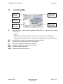
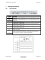
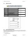
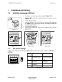
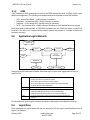
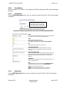
AIRIO-MCU-02
GSM/GPRS Monitor/Controller
User Manual
Version 02
www.ioselect.com
(877) 3GET-IOS
(877) 343-8467
ioSelect, Inc.
AIRIO-MCU-02 User’s Guide
Legal notice:
All rights reserved. Reproduction, transfer, distribution or storage of part or all of the contents in this
document in any form without the prior written permission of IoSelect, Inc. is prohibited. Other
product and company names mentioned herein may be trademarks or trade names of their respective
owners. Copyright © 2009, “ioSelect, Inc. “.
Disclaimer:
The use of Alarm Monitoring and Control System AIRIO-MCU-02 is at sole discretion of the user.
IoSelect, Inc. cannot be held responsible for any damages arising due to use of Alarm Monitoring and
Control System AIRIO-MCU-02. Therefore, any liability claims would be discarded.
February 2010
www.ioselect.com
858-537-2060
Page 2 of 27
ioSelect, Inc.
AIRIO-MCU-02 User’s Guide
Content
1.
2.
Attention...................................................................................................................................................................4
Safety Instructions..................................................................................................................................................4
2.1.
Disconnecting From The Main Supply.....................................................................................................5
3. Introduction .............................................................................................................................................................5
4. Technical Specification..........................................................................................................................................5
5. Mechanical Integration .........................................................................................................................................6
5.1.
Package Contents..........................................................................................................................................6
5.2.
Dimensions......................................................................................................................................................6
5.3.
Front Panel LEDs ............................................................................................................................................7
6. Wiring Connections................................................................................................................................................8
6.1.
Top Connector................................................................................................................................................8
6.2.
Bottom Connector.........................................................................................................................................9
6.3.
Serial Port (RS232 Interface)........................................................................................................................9
6.4.
Sample Electrical Connection.................................................................................................................. 10
7. Installation and Starting..................................................................................................................................... 11
7.1.
Installing / Removing a SIM Card............................................................................................................ 11
7.2.
DIP Switch Settings .................................................................................................................................... 11
7.3.
Connection To PC....................................................................................................................................... 12
7.3.1.
RS232 .................................................................................................................................................... 12
7.3.2.
SEVER Program Settings .................................................................................................................. 13
8. Application Configuration................................................................................................................................. 13
8.1.
General Overview ....................................................................................................................................... 13
8.1.1.
SMS Only.............................................................................................................................................. 13
8.1.2.
GPRS...................................................................................................................................................... 14
8.2.
Application Logical Elements.................................................................................................................. 14
8.3.
Logics Menu................................................................................................................................................. 14
8.3.1.
Events Menu ....................................................................................................................................... 16
8.4.
Actions Menu............................................................................................................................................... 19
8.5.
ROUT .............................................................................................................................................................. 19
8.6.
Message ........................................................................................................................................................ 20
8.7.
Users Menu................................................................................................................................................... 21
8.7.1.
Editing Users....................................................................................................................................... 22
8.7.2.
Editing User Groups .......................................................................................................................... 23
8.8.
Settings Menu.............................................................................................................................................. 23
8.9.
Status Menu ................................................................................................................................................. 25
8.10. System Log Menu ....................................................................................................................................... 25
8.11. Common Errors List.................................................................................................................................... 25
8.12. Tests Menu ................................................................................................................................................... 26
9. Typical ioSelect SIM Settings ............................................................................................................................ 26
9.1.
SMS Settings ................................................................................................................................................ 26
9.2.
GPRS Settings .............................................................................................................................................. 27
10.
Support.............................................................................................................................................................. 27
February 2010
www.ioselect.com
858-537-2060
Page 3 of 27
ioSelect, Inc.
AIRIO-MCU-02 User’s Guide
1.
Attention
All wireless devices for data transferring are susceptible to
interference, which could affect performance.
Only qualified personnel may install or repair this product.
The device is not water-resistant. Keep it dry.
Do not install or service device during a thunderstorm.
2.
Safety Instructions
This section will provide guidelines on how to use the AIRIO-MCU-02 safely. We suggest you adhere
to the following recommendations to avoid any damage to person or property. Familiarize yourself
with the safety requirements before using the device!
Only qualified personnel or a person who has enough
knowledge about this device and safety requirements can
perform installation and technical support of the device.
All the associated (interconnected) equipment, PC and power
supply units (PSU) shall comply with requirements of standard
IEC 60950-1.
To avoid mechanical damage of the device, transport the device packed in damage-proof packaging.
While using the device, place it such that the LEDs are visible to the user. The LEDs provide
information about the working modes and conditions of the device. Signal level of the AIRIO-MCU-02
depends on the environment in which it is working. If the device fails to work properly, only qualified
personnel may repair this product. Disconnect the device, review the contents of this manual and
ensure the SIM card is current. Contact ioSelect (www.ioselect.com) for support.
At the installation site, supply circuits must have protective devices (bipolar surge suppression device)
which provide protection from short-circuit and incorrect ground installation.
Install the power supply near the AIRIO-MCU-02.
February 2010
www.ioselect.com
858-537-2060
Page 4 of 27
ioSelect, Inc.
AIRIO-MCU-02 User’s Guide
2.1.
Disconnecting From The Main Supply
Disconnect the device from the main supply in the following order: primarily peripheral devices are
disconnected and lastly the device, for example:
In the AC main supply, disconnect the relays circuit by short-circuit back-up protection device
SF2, and then disconnect the device and all sensors by SF1.
In the DC main supply, disconnect the relays circuit SF2, and then disconnect the device and all
sensors by SF1.
When PC is connected to the device, disconnect the computer and then SF1.
3.
Introduction
AIRIO-MCU-02 is a compact alarm monitoring, status reporting, and remote control device for
electronic equipment with support of Short Messages (SMS – text messages), phone calls (Caller ID),
and with a GPRS (General Packet Radio Service) enabled SIM e-mails. The device is configurable via an
internal web server through an RS232 interface.
4.
Technical Specification
Supply 12 Vdc ±10% 200 mA
Power consumption max 5 W
Wireless modem:
o Quad Band GSM (850/900/1800/1900MHz)
Four digital inputs
o Input resistance 10 k
o “0” (false) 0 – 3 Vdc
o “1” (true) 3 – 26 Vdc
o Connector: terminal blocks
Two analog inputs.
o Voltage mode
Input resistance 60 k
Voltage range: 0 – 10 Vdc
o Current mode
Input resistance 480 +/-2%
Current range: 0-20 mA
o Resolution 10bit A/D converter
o Connectors: terminal blocks
Four relay outputs
o Rated load 240 V, 60 Hz ~7 A, 24 Vdc 10 A
o Total current 20 A
o Connectors: terminal blocks
Interfaces
o RS232
Speed: 115200 bauds
Format: 8 bits
Parity: none
Stop bits: 1
Flow control: hardware
Connector RJ45
o GSM GPRS
February 2010
www.ioselect.com
858-537-2060
Page 5 of 27
ioSelect, Inc.
AIRIO-MCU-02 User’s Guide
Alarm message service via SMS, E-Mail
Antenna MMCX connector
Protocols HTTP and SMTP
Possible configurations via internal web server interface
Watchdog controller
Operating temperature range from -20 °C to +55 °C
Relative humidity: 5…95 % (non condensing)
DIN Rail Mounting
Safety
o IEC 60950-1
o EMC
5.
Mechanical Integration
5.1.
Package Contents
1.
2.
3.
4.
5.2.
AIRIO-MCU-02;
Serial cable PORT1 (female DB-9 to RJ45);
GSM antenna (MMCX connector);
The CD with Software and User’s Manual.
Dimensions
The plastic case of AIRIO-MCU-02 is light and suitable for fitting with electronic equipment that can
hook to the DIN EN 50022 (35 mm, symmetrical DIN rail).
February 2010
2.27”
(57.6mm)
1.87”
(47.6mm)
1.28”
(32.6mm)
When planning a location for AIRIO-MCU-02, consider the GSM antenna, supplied in your package,
should NOT be placed in metal case. If you plan to mount AIRIO-MCU-02 into a metal case, please
mount the antenna outside of the metal case. If cable length is not enough, contact ioSelect to order
antennas with longer cables.
www.ioselect.com
858-537-2060
Page 6 of 27
ioSelect, Inc.
AIRIO-MCU-02 User’s Guide
5.3.
Front Panel LEDs
Device
State LEDs
Digital Input
State LEDs
Serial Port
State LEDs
Digital Output
State LEDs
Serial Port
Connector
ST
Power LED turns on when power is applied to AIRIO-MCU-02. It also shows the device’s
working status:
LED ON
LED blinks slow (0.2s ON, 0.6s OFF) – The device has registered on the GSM network
LED blinks fast (0.4s ON, 0.4s OFF) – The device is transmitting data via the GSM network
ERR
RX
TX
DIN
ROUT
RS232
Error LED turns on when the device has detected an internal fault.
Indicates receiving data from the device via serial port.
Indicates sending data to the device via serial port.
Indicates the digital input’s voltage at the ON level.
Indicates the relay output state.
Standard serial communication port.
February 2010
www.ioselect.com
858-537-2060
Page 7 of 27
ioSelect, Inc.
AIRIO-MCU-02 User’s Guide
6.
6.1.
Wiring Connections
Top Connector
Pin name
A IN 1 A IN 1 +
A IN 2 A IN 2 +
D IN 1
D IN 2
D IN 3
D IN 4
D IN 12V +
12V -
February 2010
Description
Analog input 1. Input voltage range: 0 to 10 Vdc (15 Vdc Max) or 0(4)-20 mA
(30 mA Max).
Analog input 2. Input voltage range: 0 to 10 Vdc (15 Vdc Max) or 0(4)-20 mA
(30 mA Max).
Digital input 1. This input is optically isolated from analog input and power:
0…3Vdc – false, 3…26Vdc – true.
Digital input 2. This input is optically isolated from analog input and power:
0…3Vdc – false, 3…26Vdc – true.
Digital input 3. This input is optically isolated from analog input and power:
0…3Vdc – false, 3…26Vdc – true.
Digital input 4. This input is optically isolated from analog input and power:
0…3Vdc – false, 3…26Vdc – true.
Digital input ground. It is optically isolated from module ground (power
supply, analog input).
Device supply. Voltage is 12 Vdc ±10% 200 mA max. A switching power
regulator is used inside, the smaller the voltage, the bigger the current and
vice versa (power consumption remains about the same).
www.ioselect.com
858-537-2060
Page 8 of 27
ioSelect, Inc.
AIRIO-MCU-02 User’s Guide
6.2.
Bottom Connector
Pin Name
R1 NO
R1 CO
R1 NC
R2 NO
R2 CO
R2 NC
R3 NO
R3 CO
R3 NC
R4 NO
R4 CO
R4 NC
6.3.
Description
1st Relay normally open output.
1st Relay common output.
1st Relay normally closed output.
2nd Relay normally open output.
2nd Relay common output.
2nd Relay normally closed output.
3rd Relay normally open output.
3rd Relay common output.
3rd Relay normally closed output.
4th Relay normally open output.
4th Relay common output.
4th Relay normally closed output.
Specification
Rated load 240 V, 60Hz ~7 A,
24 Vdc 10 A
Rated load 240 V, 60Hz ~7 A,
24 Vdc 10 A
Rated load 240 V, 60Hz ~7 A,
24 Vdc 10 A
Rated load 240V, 60Hz ~7 A,
24 Vdc 10 A
Serial Port (RS232 Interface)
The serial port is used for communication with internal web server. The internal web server allows
editing of configured data. The RS232 port is used only for the configuration of AIRIO-MCU-02 and is
not able to communicate with external devices.
Serial port parameters:
Interface format RS232C
February 2010
www.ioselect.com
858-537-2060
Page 9 of 27
ioSelect, Inc.
AIRIO-MCU-02 User’s Guide
Logic levels (RS232C levels)
Speed: 115200 bauds
Format: 8 bits
Parity: none
Stop bits: 1
Flow control: hardware
RS232 RJ45 connector
The communication connector is an eight-way RJ45 PLUG style connector.
RJ45 Pin number
1
2
3
4
5
6
7
8
6.4.
Description
DSR
DCD
DTR
GND
RXD
TXD
CTS
RTS
Direction
Output
Output
Input
Input
Output
Output
Input
Sample Electrical Connection
February 2010
www.ioselect.com
858-537-2060
Page 10 of 27
ioSelect, Inc.
AIRIO-MCU-02 User’s Guide
7.
7.1.
Installation and Starting
Installing / Removing a SIM Card
Remove the cover with screwdriver (see the Figure 7.1.1).
Slide the SIM card holder toward its hinge to unlock it (see the
Figure 7.1.2).
Lift the SIM card holder.
Insert the SIM card into the holder so that the notches align (see
the Figure 7.1.3). If you want to remove and already installed SIM
you can remove it now.
Close the SIM card holder.
Slide the SIM card holder away from its hinges to lock it (see the
figure 7.1.4).
Figure 7.1.1
......... . Figure 7.1.2
7.2.
Figure 7.1.3
Figure 7.1.4
DIP Switch Settings
DIP switch should be set according the Figure 7.2.1 for the normal working conditions (OFF, OFF,
OFF, ON).
ON
Figure 7.2.1
Switch
OFF
ON
number
1
Serial port works in Serial port works in
the normal mode
the “AT Command”
mode
2
Normal working
Preset factory
conditions
parameters
3
Normal working
Reset GSM module
conditions
4
“Watchdog” off
“Watchdog” on
Table 7.2.1
February 2010
www.ioselect.com
858-537-2060
Page 11 of 27
ioSelect, Inc.
AIRIO-MCU-02 User’s Guide
7.3.
Connection To PC
An RS232 connection is used to connect a PC to the unit for configuration, and the “Server” program is
run to allow the PC web browser to access teh unit.
7.3.1.
RS232
1. Install AIRIO-MCU for windows. To perform the installation, run the following programs from
your CD or download folder: AIRIO-MCU Server.msi. The program should autorun when the CD
is put into your CD drive and the door closed. If the program does not auto run: Open My
Computer, right-click on the CD drive icon and select “Explore”; Double click on “AIRIO-MCU
Server.msi” and follow the on screen
PC connection via RS232
installation instructions.
AC/DC
+24 V
2. Connect PCs serial port to the AIRIO-MCU-0x
RS232 serial port cable port.
3. After installation, run the program by clicking
On Start, All Programs, then find MCU Server
select Server.exe.
To open the program,
click the Once the icon appears on the
taskbar the program may be opened by
double-clicking on the icon.
L
N
G
AC
-
-
+
A IN 1
+
1
2
A IN 2
3
4
-
D IN
-
+
24 Vdc @ 200 mA
AIRIO-MCU-01
RS232
NO
CO
NC
NO
CO
R4
R3
R2
R1
NC
NO
CO
NC
NO
CO
NC
RS232
4. Select serial port number to which AIRIOMCU-0x is connected then click on Apply. If
you are not certain which COM port is being
used you can find the port to which the
AIRIO-MCU-0x is connected by pressing the Autodetect button.
POWER
RS232 Cable
5. Click the link: http://localhost:5000/settings the default browser window will open.
6. If you have difficulty maintaining connection to the AIRIO-MCU-0x go to Device Manager and set
your COM port settings to: 115,200 bits per second and under “Advanced…” turn off the FIFO.
After Autodetect
Select COM Port
Note: If Server.exe program is running, to reopen the program - please use the icon from the taskbar ( ).
Do NOT run the SERVER.EXE software more than one time from Start/Programs/IoSelect/MCU. If the
icon turns red ( ), close the program and reopen the Server program from the Start menu,
and then click on the http://localhost:5000/settings link to reconnect to the unit.
Note: Leaving the unit connected via RS-232 to the PC while the PC is shutdown / restarted may put the
unit in an undefined state. If this occurs, power cycle the unit for RS-232 communication to resume.
February 2010
www.ioselect.com
858-537-2060
Page 12 of 27
ioSelect, Inc.
AIRIO-MCU-02 User’s Guide
7.3.2.
SEVER Program Settings
There are three check boxes and a text box on the SERVER program‘s main dialog:
Setting
Enable CTS Flow Control
Don‘t Close Comm Port
Debug Window
TCP/IP Port Number
8.
Description
Default = ON
It is suggested to leave this on for robust operation
Default = ON
By default the SERVER program opens the COMM port once on
startup and keeps it open untill the SERVER program is closed.
On most machines this results in more robust operation.
By un-checking this box the SERVER program will open the
COMM port for every transaction with the device, and close it
once it is complete. On some computeres all this opening and
closing of the COMM port causes problems (Red SERVER Icon)
quite frequently.
Default = OFF
Turning this on will cause the server program to display debug
infomation in a window. This information may be usefull to
ioSelect technical support staff.
On some PC that presistantly have Red SERVER Icon issues
running the program with teh Debug Windows displayed may
reduce these errors.
Default = 5000
The TCP/IP port of the unit. Leave this at the default for proper
operation.
Application Configuration
Data configuration is executed by the internal web server application. You need to connect AIRIOMCU-02 to PC and run the server program to access the configuration web pages.
8.1.
General Overview
The unit can be configured in any order. For example Logics, Events, Actions, etc. can be configured in
the unit even without a SIM installed. Once the SIM is installed to get the unit fully operational some
settings changes may need to be done.
8.1.1.
SMS Only
With an SMS Only SIM it is very likely that no additional configuration is necessary and the unit will just
start working. This only setting that may need to be changes is the PIN setting (Settings Menu
PIN Code). If needed this must be obtained from the SIM provider. The SIMs phone
GSM/GPRS
number should be noted if SMS messages or Calls are to be sent to the unit.
If you are only using SMS that it is strongly suggested that you DISABLE GPRS in the unit (Settings):
February 2010
www.ioselect.com
858-537-2060
Page 13 of 27
ioSelect, Inc.
AIRIO-MCU-02 User’s Guide
8.1.2.
GPRS
A SIM enabled for GPRS, assuming you want to use GPRS features like email and Time Synch, needs
additional configuration. The following information needs to be obtained from the SIM provider:
APN – Access Point Name – Usually a string of characters
Username – For the above APN – Usually a string of characters
Password – For the above APN – Usually a string of characters
SMTP – For the above APN – Usually a string of characters or an IP address (www.xxx.yyy.zzz)
Enter these setting (Settings Menu GSM/GPRS) and restart the unit. Check the System Log and look
for errors if the unit is not communicating correctly (usually the problem is a number or letter was
entered incorrectly).
8.2.
Application Logical Elements
System log
4 IN
Events
Actions
Logics
RELAY
Users,
users groups
2 AIN
WEB server
RS232
GSM connection
Simply put the unit takes various Events, does some Logic on them, and Triggers various Actions
based on this.
Events
Logics
Actions
Users
Digital input state
Analog input above or below a threshold
An incoming phone call from a certain number
An incoming SMS from a certain number with a certain message
A certain amount of time has passed
ANDing / ORing of Various Events
Setting or Toggling a Relay Output
Sending an SMS with IO values to one or more Numbers
Sending and email with IO values to one or more Recipients
A way to name phone numbers and email entries as Individuals and
Groups
This document will go through the various configuration menu options and detail the settings.
8.3.
Logics Menu
When displayed the Logics screen will give an overview of all the Logics currently defined (List of
Logics). For example:
February 2010
www.ioselect.com
858-537-2060
Page 14 of 27
ioSelect, Inc.
AIRIO-MCU-02 User’s Guide
To create a New Logics, Press the New button. Here is where the user will define which Events will
cause which Actions. Multiple Events can be selected (use the Ctrl key and click the Event entry) to
trigger multiple Actions (same method as selecting multiple Events).
NAME:
This is the name of the logic (alphanumeric). This does not
have any effect on operation of the logic it’s just for easy
identification.
FUNCTION:
OR: Action(s) are produced when AT LEAST ONE of the
selected events is present
AND: Action(s) are produced when ALL the selected events
are present
EVENTS:
Choose an existing event name. If you want to choose
several events, click items together with the Ctrl key.
Create new events in the Events menu.
ACTIONS:
Choose existing action name. If you want to choose several
actions, click item together with the Ctrl key.
Create new actions in the Actions menu.
APPLY will save the values and stay here
SUBMIT will save the values and go back to the list of Logics
RESET will reload and display whatever is currently saved
February 2010
www.ioselect.com
858-537-2060
Page 15 of 27
ioSelect, Inc.
AIRIO-MCU-02 User’s Guide
8.3.1.
Events Menu
Events are based on the condition of the digital inputs (DIN), analog inputs (AIN), received messages,
and time.
8.3.1.1.
Analog Event
Press the NEW Analog Event button, then you will see the new item “EventX”. Click it and configure
parameters.
State Column
A shows that this item is currently Active
T shows that this item is currently True
F shows that this item is currently False
If you want to delete any listed event, mark event's checkbox and press DELETE.
NAME:
This is the name of event (alphanumeric). This does not have any effect
on operation of the event it’s just for easy identification.
TYPE:
Select the analog type from the list:
Edge Triggered: Analog UP, Analog DOWN,
Level Triggered: Analog HIGH, Analog LOW (use with CAUTION)
AIN:
Choose analog input number of interest (1 or 2).
ACTIVATION SETUP TIME:
The time interval after which the event will be sent to the logic
function if the event conditions still exist. ). Min = 0.0 Sec, Max =
6553.5 Sec.
DEACTIVATION SETUP TIME:
The time interval the condition that caused this event has to be gone
for this event to be possibly be triggered again. Essentially results in a
MINIMUM time between the same events. ). Min = 0.0 Sec, Max =
6553.5 Sec.
THRESHOLD:
Select the level of the trigger: 0 to 10 when configured for Volts or 0 to
20 when configured for mA.
GAP:
Hysteresis setting, The event will switch ON at (Threshhold+GAP/2)
and switch OFF again when the value is (Threshhold-GAP/2).
APPLY will save the values and stay here
SUBMIT will save the values and go back to the list of Events
RESET will reload and display whatever is currently saved
8.3.1.2.
Digital Event
Press the NEW Digital Event button, then you will see the new item “EventX”. Click it and configure
parameters.
February 2010
www.ioselect.com
858-537-2060
Page 16 of 27
ioSelect, Inc.
AIRIO-MCU-02 User’s Guide
State Column
A shows that this item is currently Active
T shows that this item is currently True
F shows that this item is currently False
NAME:
This is the name of event (alphanumeric). This does not have any
effect on operation of the event it’s just for easy identification.
TYPE:
Select the digital type from the list:
Edge Triggered: Digital UP, Digital DOWN,
Level Triggered: Digital HIGH, Digital LOW (use with CAUTION)
DIN:
Choose digital input number from 1 to 4.
ACTIVATION SETUP TIME:
The time interval after which the event will be sent to the logic
function if the event conditions still exist. ). Min = 0.0 Sec, Max =
6553.5 Sec.
DEACTIVATION SETUP TIME:
The time interval the condition that caused this event has to be
gone for this event to be possibly be triggered again. Essentially
results in a MINIMUM time between the same events. ). Min = 0.0
Sec, Max = 6553.5 Sec.
APPLY will save the values and stay here
SUBMIT will save the values and go back to the list of Events
RESET will reload and display whatever is currently saved
8.3.1.3.
Message Event
Press the NEW Message Event button, then you will see the new item “EventX”. Click it and configure
parameters.
State Column
A shows that this item is currently Active
T shows that this item is currently True
F shows that this item is currently False
February 2010
www.ioselect.com
858-537-2060
Page 17 of 27
ioSelect, Inc.
AIRIO-MCU-02 User’s Guide
NAME:
This is the name of event (alphanumeric). This does not have any
effect on operation of the event it’s just for easy identification.
TYPE:
There you can choose the incoming message type:
SMS – An incoming SMS message (also called a Text)
CALL – An incoming Phone call (Caller ID Only). Some SIMs must
be setup for phone call support (contact the SIM provider).
USER:
Choose the user or group of users who are allowed to SEND this
message to the unit.
Create new users and groups in the Users menu.
MESSAGE:
SMS ONLY – The text to be used to match against the incoming
message. For this event to be TRUE this text much match the
incoming SMS text EXACTLY (character to character, same case,
etc.) and is from a selected user/group of users (phone number
matches exactly).
APPLY will save the values and stay here
SUBMIT will save the values and go back to the list of Events
RESET will reload and display whatever is currently saved
8.3.1.4.
Timer Event
Timer events are used to create periodic Events based on time. For example, the unit can send a
message by SMS or e-mail every hour. Press NEW Timer Event button, then you will see the new item
“EventX”. Click it and configure parameters.
State Column
A shows that this item is currently Active
T shows that this item is currently True
F shows that this item is currently False
For “Real” dates and times to work correctly GPRS needs to be
setup and a NTP time server selected. Relative time intervals
can be used with SMS only but they will drift somewhat.
NAME:
This is the name of event (alphanumeric). This does not have
any effect on operation of the logic it’s just for easy
identification.
START TIME:
Set exact date, when the event should start.
February 2010
www.ioselect.com
858-537-2060
Page 18 of 27
ioSelect, Inc.
AIRIO-MCU-02 User’s Guide
END TIME:
Set the end time of the event.
REPETITION PERIOD:
Here you can set repetition period. Event can be repeated after
some seconds, minutes, hours, days, and/or months.
WEEKDAYS:
Set the day (days) of the week, when the event should happen.
De-selected days OVERRIDE the above settings and no
message will be sent.
This will ONLY work accurately with GPRS setup and a NTP
time server selected.
APPLY will save the values and stay here
SUBMIT will save the values and go back to the list of Events
RESET will reload and display whatever is currently saved
8.4.
Actions Menu
Actions define operations for the device to perform like turn on a relay, send an SMS, e-mail, or make a
Call (Caller ID info ONLY).
8.5.
ROUT
Press the NEW ROUT Action button, then you will see the new item “ActionX”. Click it and configure
parameters.
NAME:
This is the name of event (alphanumeric). This does not have
any effect on operation of the action it’s just for easy
identification.
TYPE:
The resulting state when the action is performed:
ON – Turn the Relay ON
OFF – Turn the Relay OFF
TOGGLE – Change the current state of the Relay
ROUT:
Choose relay number from 1 to 4.
HOLD TIME:
The time output is held in the new state. If 0.0 is entered it
means a permanent change in state). Min = 0.0 Sec, Max =
6553.5 Sec.
APPLY will save the values and stay here
SUBMIT will save the values and go back to the list of Actions
RESET will reload and display whatever is currently saved
February 2010
www.ioselect.com
858-537-2060
Page 19 of 27
ioSelect, Inc.
AIRIO-MCU-02 User’s Guide
8.6.
Message
Press the NEW Message button, then you will see the new item “ActionX”. Click it and configure
parameters. Default type is SMS, but can be changed to Call or E-Mail during configuration.
NAME:
This is the name of event (alphanumeric). This does not have
any effect on operation of the action it’s just for easy
identification.
TYPE:
Choose the outgoing message type to send the alarm:
SMS – Also called a “Text” up to 120 characters
CALL – A Phone call (Caller ID Only). Some SIMs must be
setup for actual phone call support (contact your provider).
The message box is NOT used for this type.
E-MAIL – Must have GPRS and SMTP server setup. Subject to
same length restrictions as SMS message.
USER/GROUP:
Choose the users or groups of users who would receive the
alarm.
Create Users and Groups in the Users menu.
MESSAGE:
This text message will be sent to the selected User or Group.
Please see the Format Note below for more information.
APPLY will save the values and stay here
SUBMIT will save the values and go back to the list of Actions
RESET will reload and display whatever is currently saved
Format Note
Enter a text string of no more than 120 characters (after keyword
replacement) for email and SMS. All characters are allowed except @
which is use to send internal unit values embedded in the message text
string. The defined keywords are:
@A1 - Analog Input 1. Result will be from 0.0 to 99.0 with decimal point
@A2 - Analog input 2. Result will be from 0.0 to 99.0 with decimal point
@U1 - Units of Analog Input 1 (V, mA)
@U2 - Units of Analog Input 2 (V, mA)
@D1 - Digital Input 1, Result will be symbol 0 or 1 (0 – OFF, 1 - ON)
@D2 - Digital Input 2, Result will be symbol 0 or 1 (0 – OFF, 1 - ON)
@D3 - Digital Input 3, Result will be symbol 0 or 1 (0 – OFF, 1 - ON)
@D4 - Digital Input 4, Result will be symbol 0 or 1 (0 – OFF, 1 - ON)
@R1 - Digital Relay Output 1, Result will be symbol 0 or 1 (0 – OFF, 1 - ON)
@R2 - Digital Relay Output 2, Result will be symbol 0 or 1 (0 – OFF, 1 - ON)
@R3 - Digital Relay Output 3, Result will be symbol 0 or 1 (0 – OFF, 1 - ON)
@R4 - Digital Relay Output 4, Result will be symbol 0 or 1 (0 – OFF, 1 - ON)
February 2010
www.ioselect.com
858-537-2060
Page 20 of 27
ioSelect, Inc.
AIRIO-MCU-02 User’s Guide
@PW - Mains power voltage, 0.0 – 99.0 with decimal point
@SF – Device fault status flag (OK – Device is OK, ERR – Device status fault)
@YY – Year, SMS message creation year from 0000 to 9999
@MM – Month, SMS message creation month from 00 to 99
@DD – Day, SMS message creation day from 00 to 99
@HH – Hour, SMS message creation hour from 00 to 99
@NN – Minute, SMS message creation minute from 00 to 99
@SS – Second, SMS message creation second from 00 to 99
Example (in unit SMS or email message text):
Values: @A1 @U, @R1, @D2, @R2, @PW V, Date: @MM/@DD/@YY
The resulting message being sent:
Values: 7.4 V, 1, 0, 0, 23.7 V, Date: 11/09/2009
Also, messages of the type email by default have an email subject of MCU message.
This can be changed by making the first two lines of the email text as follows:
Subject: <Your Subject>
<Blank Line>
For example, an email message text formatted like this in the unit:
Results in the following email message being received:
8.7.
Users Menu
A User is generally a phone number of someone or something getting messages from or sending
messages to the unit. The User entry is made of user name, telephone number and email address. The
user list can be edited by adding or deleting users. Press the NEW Person button to add a new user.
Press the NEW Group button to create a new Group of Users. A group is useful for sending to or
receiving messages from multiple Users. The Individual users MUST be created with NEW Person prior
to being assigned to a Group.
February 2010
www.ioselect.com
858-537-2060
Page 21 of 27
ioSelect, Inc.
AIRIO-MCU-02 User’s Guide
Whenever a User is deleted the user will be removed from all corresponding groups.
8.7.1.
Editing Users
NAME:
This is the user name (alphanumeric). This does not have any
effect on operation of the user it’s just for easy identification.
PHONE NUMBER:
Phone number of this user. Please see the Format Note below
for more information.
E-Mail:
The email address of this user ([email protected]).
APPLY will save the values and stay here
SUBMIT will save the values and go back to the list of Users
RESET will reload and display whatever is currently saved
Format Note
The unit uses exact matching of incoming phone numbers versus the
users defined. This can lead to some issues because different SIM
providers can send the SMS or Call with different format of phone
numbers. The most common are:
10 Digit Format: xxxyyyzzzz
11 Digit Format: 1xxxyyyzzzz
+11 Digit Format: +1xxxyyyzzzz
SIM obtained directly from ioSelect typically use the +11 Digit Format, but
there is usually no way to tell what format the phone numbers will be in
with any give companies SIM. The best way to proceed is to enter the
phone number in for a user in 10 Digit Format, and they do a test call to
the device. If it works… Great! If not check the System Log webpage and
there should be an error something like this:
Note the format of the incoming number (in this case +11 Digit) and
make changes to your users phone numbers accordingly. Any of the
above formats will work when sending an SMS or Call to a user, this is only
an issue for the unit receiving an SMS or a Call from a user.
February 2010
www.ioselect.com
858-537-2060
Page 22 of 27
ioSelect, Inc.
AIRIO-MCU-02 User’s Guide
8.7.2.
Editing User Groups
NAME:
This is the user group name (alphanumeric). This does not have
any effect on operation of the group it’s just for easy
identification.
USERS:
Choose and existing user(s) names. If you want to choose several
users, click items together with the Ctrl key.
Create new users in the Users menu.
APPLY will save the values and stay here
SUBMIT will save the values and go back to the list of Users
RESET will reload and display whatever is currently saved
8.8.
Settings Menu
Analog Inputs:
Analog input has two modes:
VOLTAGE – 0 to 10VDC, CURRENT – 4 to 20 mA. The unit is NOT
factory calibrated. Use the Calibrate buttons to change the
calibration for 0V (minimum) or 10V (maximum). Apply the
appropriate Voltage / Current to the desired input and press the
appropriate button. After all changes are completed press Apply
changes. These changes will be permanently saved to flash and will
be retained through power cycles to the unit.
The current unit read value is located in the Value column.
Refresh the webpage to see the latest.
Fault Relay:
Here you can set Fault Relay that will turn on when the unit detects
an error (ERR LED is ON). ROUT is from 1 to 4. After all changes
press Apply changes.
Date and Time:
Manual Time Set (YYYY.MM.DD) and time (HH:MM:SS). Will be
overridden if at Time Synch Server is used. After all changes are
completed press Apply changes.
Timezone and Daylight Saving:
Timezone and Daylight Saving setting. Timezone is the offset
versus GMT. After all changes are completed press Apply changes.
In North America we suggest selecting NONE for Daylight
Savings Time Rules.
Time Synchronization Server:
Enter a DNS name or IP address of a NTP/SNTP time server to use
for time synch. In general, Mode should be set to Unicast and
Timeout set to several hours (do not need to check very often).
After all changes are completed press Apply changes.
GSM/GPRS:
GPRS Settings – This is specific to a particular SIM provider. Use the
Authentication method of Auto unless specifically directed
otherwise by your SIM provider. After all changes are completed
press Apply changes.
Contact your SIM provider for APN, Username, Password, and
PIN (if used).
E-Mail:
EMAIL Settings – This is specific to a particular SIM provider. The
February 2010
www.ioselect.com
858-537-2060
Page 23 of 27
ioSelect, Inc.
AIRIO-MCU-02 User’s Guide
Sender Address can be anything, this entry shows up in the “From”
field in the sent email message (See Format Note Below). After all
changes are completed press Apply changes.
Contact your SIM provider for their SMTP DNS name or IP
Address.
Authorization:
This Username and Password in order to protect the Units settings
from unauthorized people. After all changes are completed press
Apply changes.
SMS Center Number:
The default SMS Center Number comes on the SIM and is typically
fine, but it can be overridden if needed. After all changes are
completed press Apply changes.
Bridged Network Connection:
Here you can set user to whom a Bridged Network connection is
allowed. After all changes are completed press Apply changes.
Language Selection:
Set the appropriate language for the unit. After all changes are
completed press Apply changes.
Options:
Show detailed Logics summary screen or not. After all changes are
completed press Apply changes.
Download Configuration:
Pressing this link will create a file on the PC’s hard drive with the
current configuration of the unit.
Upload Configuration:
You can enter in a path on you hard drive (or Browse) to a file that
contains a previously saved configuration of a unit and reload this
configuration (Submit).
Saved configurations can ONLY be loaded into units with the
SAME version of firmware.
Format Note
When using the Sender Address field care must be taken otherwise email
sending can fail. If no sting is entered then the email messages will be
sent with no “From” address. If only a partial email address string is given
(For example: MCU01) the resulting “From” address will be
MCU01@<email of provider> where <email of provider> depends on the
SIM provider. If ioSelect is providing the SIM it will be k2.wyless.com, so
in the example above the resulting “From” address will be
[email protected]. If a complete email address string is provided
then the “From” field will be this sting. For example if
[email protected] is entered then the resulting “Form” address will
be [email protected] (capitalized as entered).
Whatever is entered here MUST result in a valid string format for an email
address (for example spaces are not allowed). If ANY invalid characters are
entered all email sending will FAIL. The resulting string does not have to
actually be a working email address, but the FORMAT of the resulting email
address string MUST be valid.
February 2010
www.ioselect.com
858-537-2060
Page 24 of 27
ioSelect, Inc.
AIRIO-MCU-02 User’s Guide
8.9.
Status Menu
The Status Menu shows a summary of the operational state of the unit from a comms perspective.
Current date, time and Timezone settings.
Here you can see the firmware version number in the unit.
IMEI - International Mobile Equipment Identity – Unique number
identifying this device (Not the SIM).
With a new SIM card it may need changed parameters in the settings
menu. This is ALWAYS true with GPRS, but with SMS it may be that no
changes are required. Some errors may be displayed here
SMS_ERR_SIM_CARD means there in no or a corrupted SIM card is
installed.
With GPRS configured and a NTP/SNTP Time Synch Server selected in the
Setting Menu, this will show the current Time Synch status. With SMS only
SIMs this will ALWAYS show NOT Synched.
8.10.
System Log Menu
The Log shows the events that take place during startup and network registration. Also, it will list
various errors that occur during operation. It can be useful when troubleshooting.
To see the latest entries in the Log – press the
REFRESH button. To clear the log press ERASE. The
log overwrites with a first in, first out method. The
DISABLE button terminates the logging ability (not
recommended).
Except for startup information and time synch
notifications, in general the log only shows errors
of some kind.
8.11.
Common Errors List
SMS_ERR_SIM_CARD
February 2010
Message means that no or a corrupted SIM
card is installed
www.ioselect.com
858-537-2060
Page 25 of 27
ioSelect, Inc.
AIRIO-MCU-02 User’s Guide
8.12.
SMS_ERR_NEED_PIN_CODE
Message means that a PIN code must be
entered in Settings Menu for this SIM card.
SMS_ERR_CANT_REG_NETWORK
Message means that a there is a problem with
the APN/Username/Password entered in
Settings Menu for this SIM card.
Tests Menu
This displays the current inputs and output of the unit, and gives the ability to manually change the
ROUTs. Access tests menu: http://localhost:5000/test
Please use care when using this page. Many of
these entries are only useful to ioSelect product
support staff.
Use check boxes to turn ON (Checked) or
turn OFF (Unchecked) the ROUTS. Press the
Apply button to activate.
Shows the current values on AI1 and AI2
Press the Apply button to activate the
changes.
Current Voltage to CPU
Current Voltage to Unit
Current DIP switch settings and Current
Warnings
Refresh this display
Restart Silent – Restarts the GSM Modem
Restart soft error – Restarts the entire unit
9.
Typical ioSelect SIM Settings
These are for ioSelect supplied SIMs only. For other SIM please contact your SIM provider:
9.1.
SMS Settings
Once the SIM is installed SMS communications should just work. Phone numbers on incoming SMS
messages to the unit are in +11 Digit Format. Incoming Calls are in 11 Digit Format. Therefore,
different users must be created for incoming SMS and incoming Calls (User1-SMS and User1-Call)
because the number formats are different.
February 2010
www.ioselect.com
858-537-2060
Page 26 of 27
ioSelect, Inc.
AIRIO-MCU-02 User’s Guide
9.2.
GPRS Settings
Use the following (Other time Synch Servers – NTP Servers – can be used, but this should work):
APN:
Username:
Password:
SMTP:
Time Synch Server:
telargo.t-mobile.com
""
Nothing (blank)
""
Nothing (blank)
smtp.wyless.net
nist1.symmetricom.com (Use unicast and a timeout of 2 hours or more)
10. Support
Before contacting us for support, make sure that you went through the above manual thoroughly. If
you are still facing problems, feel free to contact our technical support team at [email protected],
we would be glad to help you.
February 2010
www.ioselect.com
858-537-2060
Page 27 of 27


![[ActionX DVS5G9]を 豊富なオプションと](http://vs1.manualzilla.com/store/data/006551907_2-22955ea2d03d47ae9c24816caac3a79d-150x150.png)