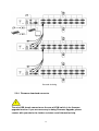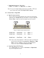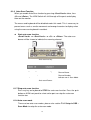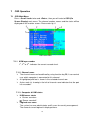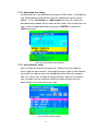
1
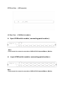
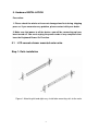
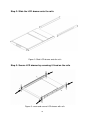
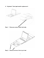
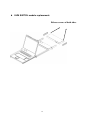
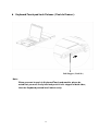
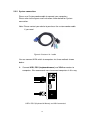
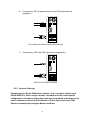
17” / 19” LCD Console with Modularized combo KVM switch User Manual Version 1.0 Index 1. INTRODUCTION……………………………………………………………………………………………2 1.1 OVERVIEW …………………….…..………………………………….………………………… ………2 1.2 FEATURES………… …………………………………...……………..…………………………………3 1.3 Package Contents………………….…………………………...………………………4 2. SPECIFICATIONS…………………………………………………………………………………………..4 2.1 GENERAL……………………………………………………………...…………………………………4 3. REQUIREMENT……………………………………………………………………………………………6 3.1 CONFIGUARATION DIAGRAM OF CONNECTIONS……….……………………………….………………..5 3.2 COMPONENTS…………………….....................……………..………….…………………………….5 4. COMPONENTS……………….. ………………………..………….…….…..……………………………7 5. HARDWARE INSTALLATION………………………..…….…..…………………………………….……9 5.1 LCD CONSOLE MOUNTED ONTO RACKS……………..………………………………………...9 5.2 KVM SWITCH INSTALLATION………………………………………………………………….….13 6. OPERATION……………………………………………………….…….…..………………………….…18 6.1 HOT KEY OPERATION...……………..………….…………………………………….17 7. OSD OPERATION….………………………….…….…..……………………………………………..…24 8. SUN MICROSYSTEMS FUNCTION KEY EMULATION….…..…………………………….………..35 1 1. Introduction Thank you for purchasing the LCD Console (with modularized combo KVM Switch). We recommend that you read this manual thoroughly and retain for future reference. 1.1 Overview The LCD console drawer (with modularized combo KVM switch) is an ideal module solution featuring an integrated 17-inch or 19-inch TFT LCD color display and ultra-high-quality compact industrial Keyboard / touchpad in 1U, rack-mountable design provides user-friendly oriented and the most reliable operation environment for network administrators. The console drawer is similar to the front-end Console module provides flicker-free color images at optimal resolutions, and has an ergonomically designed operation functionalities to increase more convenient to users. Installation setup is designated by single person easily. Simply use the supplied combo VGA cable set to link the ports to the console ports of your KVM switch, no matter what you connected interfaces ports of KVM switch, USB or PS/2. On-Screen menus allow for display adjustments. For convenience, there are additional external combo console ports, built in with modularized KVM switch, connected with PS/2 or USB keyboard, mouse, and video are also provided instead of built-in originally. By the way, we are also providing modularized modules design for LCD panel, keyboard / touchpad , front panel – push buttons and KVM switch to enhance convenience if one of them alternatively is happening out of order, then new one replaced could be implemented immediately and no more confront any obstacles of your keeping working on. The LCD console KVM switch is built on a modularized design, and KVM section is able to be detached from the switch section for convenient maintenance. Furthermore, the keyboard / touchpad module is also easily removed changing by required with variety of languages. 2 1.2 Features The LCD console (with modularized combo KVM switch ) is a LCD console featuring an integrated 17-inch or 19-inch LCD panel module and keyboard module with touchpad in a 1U chassis. The unique module design solution is for easy installation and maintenance. LCD console drawer Rack mountable in 19” system rack (1U). Supports PS/2 KB/Mouse Touchpad mouse owns up-down scrolling function LED Display for easy status monitoring. One person Easy-Installation. Module design for easy installation and maintenance. The keyboard / touchpad module is also easily removed changing by required with variety of languages. Modularized KVM switch module Connects dual interfaces of computers via PS/2 and/or USB at will. Supports Windows 98/98SE/2000/ME/XP/Vista, Win NT, Unix, Linux, Mac OS9/OSX , SUN Microsystems. Auto PS/2 and USB interface detection Supports resolution up to 1280 x 1024 On-Screen-Display (OSD) and Cascade Chain functions. OSD is intuitive menus driven for quick and efficient navigation. An extra combo console for both PS/2 and USB is provided on the rear panel of KVM switch to manage LCD console KVM switch from an external console. Supports cascadable chain with 3 levels, control up to 64/256/4096 PCs, from a single console,cascaded unit does not need special configuration. 3 types of KVM switching: - Front panel Push Button - Hot-Key on LCD built keyboard or extra combo console PS/2 & USB keyboard - Menu driven OSD ( On-Screen-Display ) Auto-Scan function ( Time interval can be adjsuted between 5-20 seconds when the Auto-Scan is enabled.) 3 Plug and Play ( Windows 98/SE users might need your Windows CD to install the HID driver for USB keyboard/mouse.) KVM firmware is upgradable via on-board mini-USB download connector and extenal mini-programmer. 1.3 Package Contents 1. LCD console drawer ( or with modularized combo KVM switch ) x 2. Custom 4-in-1 cable set x 1 3. Power adaptor DC 12V x 1 1 4. User Manual x 1 5. Rack Mountable Kit x 1 2. Specifications LCD Console Model No. KL-2701 / KL-2708 / KL-2716 Standard Display Size Panel Type Resolution Pixel Pitch Viewing Angle(CR>10) Contrast Ratio Supported Colors Response Time Brightness Back Light Lifetime Operating System Multi Platform System Cables Keyboard Mouse Power Supply Operation Temperature Storage Temperature Humidity Chassis Construction Keyboard Languages ( Modular ) Certifications Dimension Meets EIA RS-310C 1U 19” Rack-Mount standard 17” 19” Active Matrix TFT LCD Maximum Resolution up to 1280 x 1024 (SXGA) 0.264 (H) x 0.264 (V) 0.294 (H) x 0.2694 (V) 160/160 (Typ.) 160/160 (Typ.) 700 : 1 800 : 1 16.2M 16.7M 5ms 5ms 300cd/m2 30000~50000 hours Windows / Linux / Sun Microsystems Support PS/2 3 in1 VGA Cable ( PS/2 * 2 + D-SUB 15 pin ) 104 Keyboard / Touch Pad Universal 90~264VAC input , 12V DC output 0~50 oC -20 ~ 60 oC 5-95%, non-condensing Metal English / Germany / French / Italy / Spanish / U.K. Chinese / Japanese CE / FCC (L) 69 x (W) 44.5 x (H) 4.2 cm N.W. 13.6 kgs (KL-2701) ; 13.8 kgs (KL-2901) G.W. 16.1 kgs (KL-2701) ; 16.3 kgs (KL-2901) 4 KL-2901/KL-2908 / KL-2916 KVM Switch module Model No. Standard Number of ports Display Size Selection Method KL-2708 / KL-2716 KL-2908 / KL-2916 Meets EIA RS-310C 1U 19” Rack-Mount standard 8-port / 16-port 17” 19” (1). Front Panel – Push Button (2). Hot-Keys on built Keyboard and extra console KB (3). OSD ( On-Screen-Display ) LEDs ( front panel-Push Button) PC connectors Red for PC Selection Green for PC on-Line ready Video 8 / 16 * HDB-15 female (KB/MS) ( PS/2 & USB signals combined ) Extra Console Keyboard Mouse Video Keyboard Mouse Firmware Upgrade Con. Auto-Scan Interval Resolution Hot Swappable Operation systems Operation Temperature Storage Temperature Housing chassis Dimension 1 x 6 pin mini-DIN female 1 x 6 pin mini-DIN female 1 x HDB-15 female 1 x USB – A type female 1 x USB – A type female Mini USB female Adjustable time setting by OSD menu driven 2048 x 1536@60Hz DDC , DDC2 Yes Windows 98SE/ME/2000/XP/2003 server/Vista, Linux, Mac OS9/OSX, and SUN Microsystems 0 ~ 50 oC -20 ~ 60 oC Metal (L) 44 x (W) 20.5 x (H) 4.2 cm 5 3. Requirements KVM Switch Extra Console ( Remote Control ): The following hardware components are required for the extra external console: A VGA, SVGA, or multisync monitor capable of displaying the highest resolution provided by any computer in the installation. A PS/2 or USB keyboard and mouse Computers The following equipment must be installed on each computer: A VGA, SVGA, or multisync video graphics card with an HDB-15 port. Note: The maximum resolution of integrated LCD monitors is 1280 x 1024. Please make sure that none of the computer resolution settings exceed the maximum resolution of LCD monitors. PS/2 mouse and keyboard ports ( 6-pin Mini-DIN), or at least one USB port. Cables For optimum signal integrity and to simply the layout, we strongly recommend that you use the high quality specific custom cables sets described below: LCD console Computer connected Function LCD console to computer ( 3 – in -1 ) KVM switch to computer ( 4 – in- 1 ) KVM Switch Computers connected Interface PS/2 Length 1.8 m PS/2 & USB 1.8 m 3.0 m 5.0 m 6 4. Components 4.1 Front View 3 1 9 8 5 2 4 6 7 No. Component 1 2 3 4 5 6 7 8 9 LCD Handle Bar Rail Lock LCD Panel OSD Buttons Keyboard Module Power LED Indicators Slide Rail x 2 Touch Pad KVM Switch Push Buttons KVM Switch Module Function Description Release / Fold-up LCD panel Console Drawer Locker ( Left Right ) Controls Display Required Quality Keyboard / Touch Pad Operation Indicates Power Status Slide Rails for Mountable Racks Mouse Operation PC Selected PC connected 7 4.2 Rear View ( LCD console ) 4.3 Rear View ( KVM Switch module ) 8-port KVM switch module ( connecting ports location ): Note: Extra console for external connection of USB & PS/2 Keyboard/Mouse, Monitor. 16-port KVM switch module ( connecting ports location ): Note: Extra console for external connection of USB & PS/2 Keyboard/Mouse, Monitor. 8 5. Hardware INSTALLATION Precaution: 1. Please check the whole unit was not damaged and lost during shipping process. If you encounter any problem, please contact with your dealer. 2. Make sure that power to all the devices you will be connecting up have been turned off. You must unplug the power cords of any computers that have the Keyboard Power On Function. 5.1 LCD console drawer mounted onto racks. Step 1: Rails installation Figure 1: Attaching left and right easy-installation mounting rails to the racks 9 Step 2: Slide the LCD drawer onto the rails Figure 2: Slide LCD drawer onto the rails Step 3: Secure LCD drawer by screwing it fixed on the rails Figure 3: screw and secure LCD drawer with rails 10 Keyboard / Touch pad module replacement: Step 1. Releases screws of both rails side. Step 2. Release screws of front cycle lock. 11 KVM SWITCH module replacement: Release screws of both sides. 12 Keyboard/Touch pad Lock Release ( Push-In Drawer ): Rail Stopper ( Push-In ) Note: When you want to push in Keyboard/Touch pad module, please be noted that you must firstly hold and push in rails stopper of both sides, then the Keyboard pushed into Cabinet easily. 13 5.2 KVM SWITCH INSTALLATION Precaution: Please turn off computers and devices when you start to install KVM Switch. For computers with Keyboard Power On function, please unplug the power cords in advance. Otherwise, the switch might not work properly. If your computeres work under Windows 98, please connect KVM switch to computers via PS/2 ports, because Windows 98 does not support installation at first time as through USB HID installation driver. Some old computers must enable USB setting in BIOS in advance to make USB interface work. This KVM switch does not guarantee to fully support USB keyboard with USB HUB built-in itself. 5.2.1 KVM SWITCH Console connection: Plug keyboard, mouse and monitor to the console ports on the real panel of KVM Switch. Console connection 14 5.2.2 System connection: Please use Custom combo cable to connect your computers. Please refer to the figures and instruction shown below for System connection. Note: Please contact your dealer to purchase the custom combo cable if you need. Figure 6: Custom 4-in-1 cable You can connect KVM switch to computers via three methods shown below: A. Connect USB, PS/2 (keyboard/mouse) and VGA connectors to computers. We recommand users to connect computers in this way. USB & PS/2 (Keyboard & Mouse) and VGA connected 15 B. Connect only PS/2 (keyboard/mouse) and VGA connectors to computers. PS/2 (Keyboard & Mouse) and VGA connected C. Connect only USB and VGA connectors to computers. USB and VGA video connected 5.2.3 Cascade Chaining Combo 8-port & 16-port KVM switch support 3 level cascades; control up to 64/256/4096 PCs, from a single console; cascaded units don’t need special configuration. Cascade configuration expands system ability and allows you to select computers connected to the Master or Slave. After connected, KVM Switches automatically configure Master and Slave. 16 To Install cascade chain, please follow the instruction below: A. Please turn off computers and devices when you start to install KVM Switch. B. Use the custom combo cable set (See Figure 6), to connect one or more Slave KVM Switches to any PC port of Master KVM Switch. The connection between KVM to KVM must be connected through PS/2 connection. ( Please refer to Figure 7 & Figure 8 ). C. You can do console Master KVM Switch via either USB and/or PS/2 keyboard and mouse at will. D. Plug in the power adapter of the first level Master KVM Switch and connect Master KVM switch to computers. E. Next, plug in power adapter for each level Slave KVM Switch and connect Slave KVM switch to computers . F. The power on sequence should be: 1. Master KVM Switch 2. 3. 4. Second level Slave KVM Switch (connecting to Master KVM Switch) if any. Third level Slave KVM Switch (connecting to second level Slave KVM Switch) if any. All computers connecting to Master/Slave KVM Switch. G. After all KVM Switches are powerd by power adaptor, trun on the computers. Initial Plug-in Process: Please plug in the Master KVM Switch first before turning on any other devices like montior or computers. Hot plug and Hot Swap: Combo Free 8-port & 16-port KVM switch support Hot plug and Hot swap function. 17 Cascade chaining 5.2.4 Firmware download connector ! The min-USB female connector on the rear of KVM switch is for firmware upgrade function. If you are necessary to doing Firmware Upgrade, please contact with your dealer for further assistance and information help. 18 6. Operation You can control computers via 8-Port or 16-Port Combo KVM Switch by front push button, hotkeys and OSD. 1. Push button operation Press the front panel push button to select the PC and operate it. 2. Hot Key operation Please refer section 6. HotKey Operation. 3. OSD operation Please refer section 7. OSD Operation. 6.1 Hot Key Operation 6.1.1 Call OSD Menu Press < Scroll Lock> twice and <Enter>, then the OSD “Main Menu” will be displayed on the monitor screen. All of the KVM parameters can be setup in OSD mode. You can also execute some KVM functions in OSD. <Scroll Lock> → <Scroll Lock> → <Enter> 6.1.2 Leading Hot Key Select The two-steps hot key sequence is used for quick function execution. The leading key is <Scroll Lock> by default. However, you can change the leading hot key if you want. By pressing <CTRL> twice, <New Hot Key>, then press <Enter>, you can change the leading hot key. The available leading hot key are <Scroll Lock>, < Num Lock > or < Caps Lock > for option. Setup leading hot key to < Scroll Lock > < CTRL > → < CTRL > → < Scroll Lock > → < Enter > Setup leading hot key to < Num Lock> < CTRL > → < CTRL > → < Num Lock > → < Enter > 19 Setup leading hot key to < Caps Lock > < CTRL > → < CTRL > → < Caps Lock > → < Enter > Note: You can also change leading hot key by pressing <F1> in OSD main menu. Please refer section 7.3.5 Setup in OSD – Hot Key. 6.1.3 Channel Select - Single KVM Specific channel selection You can select the connected computers by using the two-step Hot Key sequence. Press <Scroll Lock> key twice (Step 1), then press key (1 to 16) and <Enter> (step 2) to select the computer you want to control. Figure 12: Specific channel selection hot key … … <Scroll Lock> → <Scroll Lock> → <1> → <Enter> or <Scroll Lock> → <Scroll Lock> → <2> → <Enter> or <Scroll Lock> → <Scroll Lock> → <16> → <Enter> Note: You can also select computers in OSD menu. Move the indicator bar to the chanel to switch by using <arrow key>, <Page Up> or <Page Down>, then press <Enter> to select the connected computer. Please refer section 7.2 Channel Selection in OSD. Arrow Key Channel Shift Function Press <Scroll Lock> twice, and press <Left Arrow> or <Right Arrow> key to shift left/right one channel. 20 Switch to left one channel <Scroll Lock> → <Scroll Lock> → <Left Arrow> Switch to right one channel <Scroll Lock> → <Scroll Lock> → <Right Arrow> <ALT> Channel Shift Function 1. Start <ALT> Channel shift Function < ALT > channel shift function default was off. You can press Hot-Key <Scroll Lock> twice, <ALT> and then press <Enter> to turn on or turn off this function alternately. 2. Shift the channel by <ALT> key Press left < ALT > or right < ALT > key twice, the PC channel will automatically shift to left or right one channel (channel decrease / increase to next) when < ALT > channel shift function is enabled. Enable/Disable <ALT> channel shift function <Scroll Lock> → <Scroll Lock> → < ALT > → <Enter> Switch to left one channel <Left ALT> → < Left ALT > Switch to right one channel <Right ALT> → < Right ALT > 6.1.4 Channel Select - Cascade Chain Layer You can select the active channel directly under cascade chain connection. The following hot key sequence is used for quick channel selection. Press <Scroll Lock> twice, <D>, the cascade channel number (1, 2, 3……16), and Press <Enter>. Channel select to first layer < Scroll Lock > → < Scroll Lock > → <D> → < CH-L1 > → < Enter > Channel select to second layer < Scroll Lock > → < Scroll Lock > → <D> → < CH- L1 > → <D> → < CH-L2 > → < Enter > 21 Channel select to third layer < Scroll Lock > → < Scroll Lock > → <D> → <CH-L1 > → <D> → < CH-L2 > → <D> → < CH-L3 > → < Enter > Note: With cascading 3 layers, you can select last layer directly; Example: press <Scroll Lock> twice, then D2D5D7, and <Enter>: D2 : layer 1 channel 2 links to D5 : layer 2 channel 5 links to D7 : layer 3 channel 7 selected Note: You can also select active channel of cascade chain in OSD menu. Move the indicator bar to the chanel to switch by using <arrow key>, <Page Up> or <Page Down>, and then press <Enter> to switch to the target port. Please refer section 7.2.2 Channel select to cascade port. 6.1.5 Buzzer sound Disable / Enable Press <Scroll Lock> twice, then <B> and <Enter>. The buzzer sound will be disabled / enabled alternately. The buzzer sound default setting is ON. <Scroll Lock> → <Scroll Lock> → <B> → <Enter> Note: You can also enable/disable buzzer sound by pressing <F1> in OSD main menu. Please refer section 7.3.6 Setup in OSD - Sound. . Buzzer setup hot key 22 6.1.6 Auto-Scan Function When you enable Auto-Scan function by pressing <Scroll Lock> twice, then <S> and <Enter>. The KVM Switch will shift through all the ports and display them on the monitor. The mouse and keyboard will be disabled under this mode. This is necessary to prevent errors such as erratic movement and wrong characters to display when using the mouse or keyboard in accident. Start auto-scan function <Scroll Lock> → <Scroll Lock> → <S> → <Enter>. The auto-scan banner will be shown to indicate the scanning channel. Auto-scan hot key ─┬── ┬ ──┬────── │ │ └─ Channel Name │ └────────── Channel Number └─────────────── Indicate now is Scan Mode Auto-scan Banner 6.1.7 Stop auto-scan function Press any key on keyboard to STOP the auto-scan function. Press the push button on KVM front panel to select active port can stop the auto-scan function too. 6.1.8 Auto-scan mode There are two auto-scan modes, please refer section 7.3.1 Setup in OSD – Scan Mode to setup the auto-scan mode. 23 Scan all working computers. Scan all computers which are marked for auto-scan. 6.1.9 Auto-scan time interval The auto-scan time interval can be adjustable by pressing <F1> in OSD main menu. Please refer section 7.3.1 Setup in OSD – Scan Time. Note: You can also start auto-scan function by pressing <F2> in OSD main menu. Please refer section 7.4 Auto-Scan in OSD. 6.1.10 Console Lock If the security mode is enabled in OSD mode (by pressing <F5> in OSD mode), you can lock console by pressing <Scroll Lock> twice, and then <H> and <Enter>. The KVM will be locked until an authorized user login. <Scroll Lock> → <Scroll Lock> → <H> → <Enter> To unlock console, please press any key according to screen message, then key in User Name and Password. The KVM switch and console devices will be unlocked and back to normal status. Note: You can also execute console lock function by pressing <F3> in OSD main menu. Please refer section 7.5 Console Lock in OSD. 24 7 OSD Operation 7.1 OSD Main Menu Press < Scroll Lock> twice and <Enter>, then you will enter to OSD (On Screen Display) main menu. The channel number, names and the status will be displayed on the monitor screen. Please refer fig. 8 OSD main menu 7.1.1 KVM layer number 1st, 2nd or 3rd. indicates thescurrent cascade level. s 7.1.2 Channel name The channel name can be defined by using function key F4, it can remind user which computer is connected to this channel. A highlighted pink bar is shown in the selected channel row. A plus mark (+) showing in the left of channel name indicates that the port has cascades. 7.1.3 Computer & KVM status KVM buzzer stauts Buzzer sound on Buzzer sound off Logined user name The system has one administrator and 3 users for security management. The name of current logined is displayed here. 25 Channel LOCK indicator ( Status STA ) L: Indicating this channel is locked. BLANK: Indicating this channel is normal without locked. Computer power on indicator ( Status STA ), OSD menu will update the flag automatically if the computer status is changed A: Indicating this computer is powered on and ready to select. BLANK: Indicating this computer is not connected or powered on. Channel scan indicator ( Status STA ) S: This channel is marked for auto-scan if the scan mode is Select type. BLANK: Indicating this computer is not marked for auto-scan. 7.1.4 Current active channel number Indicate current active channel number. The channel of the currently selected computer is displayed in the right-upper corner. If the active channel is in 2nd or 3rd cascade layer, the display string is like XX-YY-ZZ. For example, 02-05-07 means the active channel is layer 1 channel 2 links to layer 2 channel 5, and layer 3 channel 7 is selected as active channel. 7.1.5 Cascade parent channel number Indicate the parent channel of this cascade layer. The number at the left-upper corner below KVM layer number shows the number of port for the upper layer, i.e. 8 means link from channel 8 of upper KVM. It’s valid only for 2nd and 3rd cascade layer. It will show blank for 1st layer since there is no parent channel. 7.1.6 Page down / up indicator This is for 16-port KVM only. The information of port 1 ~ 8 are display in the first page, and information of port 9 ~ 16 are display in the second page. Since the port information is divide to two pages, the page down / up indicator can remind you to switch to alternative page by using <page down> and <page up> key. 7.1.7 Function Control Menu The detail of control functions will be described in later sections. The list of control functions: F1: Set up: basic set up menu F2: Scan: autoscan function 26 F3: Lock: setup lock/unlock, only available when F5 Security is enabled. F4: Rename: rename selected channel name. F5: Security: security function and user authority settings F6: Lock Port: PC port lock function (for administrator only) 7.2 Channel selection in OSD 7.2.1 Channel select to computer Use the <UP> and <DOWN> arrow keys to highlight a computer and then <ENTER> to select it and leave OSD menu. A banner with the channel name will be shown on left-upper corner of the screen. ┬ ────┬────── │ └ Channel Name └──────────── Channel Number Channel Banner (Single Layer) 7.2.2 Channel select to cascade port A plus mark (+) showing in the left of channel name indicates that the port s Pressing <ENTER> in this channel will enter is under cascade channing. s one level down, and the screen pops up the listing of the computers of the slave KVM. ┬ ┬ ┬ ────┬────── │ │ │ └ Channel Name │ │ └─────── Channel Number │ └────────── 2 Layer Channel Number └────────────── 1 Layer Channel Number nd st Channel Banner (Cascade Layer) 7.2.3 Return from cascade port After entering cascade port, press <R> will return to upper layer OSD s menu. s 27 7.3 Setup in OSD: <F1> Please use <Up> or <Down> arrow key to select the item you want to change, and use <Left> or <Right> arrow key to change the settings. Press <ESC> to exit and save the setup settings. OSD Setup 7.3.1 Scan Mode Select: Scan the selected channels marked with S in STA column on OSD main menu. PC ON: Scan all powered on PC channels 7.3.2 Scan Time The default scan time is 5 seconds. It can be changed up to 90 seconds by stepping 5 seconds. 7.3.3 Banner Time The default banner time is 5 seconds. It can be changed to 10 seconds, 15 seconds, or always on (∞). 7.3.4 Position Menu: Use four arrow keys to move the OSD main menu to the desired position. Press <ESC> to save the changed menu position. 28 Menu Position Setup Banner: Use four arrow keys to move the channel banner to the desired position. Press <ESC> to save the changed banner position. Banner Position Setup 7.3.5 Hot key Scroll Lock: <Scroll Lock> becomes the hot key. Num Lock: <Num Lock> becomes the hot key. Cap Lock: <Cap Lock> becomes the hot key. Note: You can also change leading hot key via hot key by using < CTRL > → < CTRL > → < New Hotkey > → < Enter > outside the OSD mode. Please refer section 6.2 Leading Hot Key Select. 7.3.6 Sound ON: Buzzer sound enabled. OFF: Buzzer sound disabled. Note: You can also enable/disable buzzer sound via hot key by using <Scroll Lock> → <Scroll Lock> → <B> → <Enter> outside the OSD mode. Please refer section 6.5 Buzzer sound Disable / Enable. 7.3.7 Language English (En) / Deutsch (De) / Francais (Fr), 3 languages are available. 29 7.4 Auto-Scan in OSD: <F2> 7.4.1 Start to auto-scan in OSD Press <F2> in OSD main menu. The auto-scan banner will be shown to indicate the scanning channel. ─┬── ┬ ──┬────── │ │ └─ Channel Name │ └────────── Channel Number └─────────────── Indicate now is Scan Mode Auto-Scan Banner Note: You can also start auto-scan function via hot key by using <Scroll Lock> → <Scroll Lock> → <S> → <Enter> outside the OSD mode. Please refer section 6.6.1 Start Auto-Scan Function. 7.4.2 Stop auto-scan Press any key on keyboard to STOP the auto-scan function. The auto-scan banner will disappear when the scan stops. 7.4.3 Auto-scan mode There are two auto-scan modes, please refer section 7.3.1 Setup in OSD – Scan Mode to set up the auto-scan mode. Scan all computers which are power on. Scan all computers which are marked for auto-scan. 7.4.4 Auto-scan time interval The auto-scan time interval of each port displayed can be adjustable by pressing <F1> in OSD main menu. Please refer section 7.3.2 Setup in OSD – Scan Time. 30 7.5 Console Lock in OSD: <F3> If the security mode is enabled in OSD mode (by pressing <F5> in OSD mode, please refer section 7.7 Security Setup in OSD). You can logout to lock console by pressing <F3> In OSD mode. The Console Lock Banner will be shown on the screen. Console Lock Banner The KVM will be locked until an authorized user login. Unlock window Note: You can also logout to lock console via hot key by using <Scroll Lock> → <Scroll Lock> → <H> → <Enter> outside the OSD mode. Please refer section 6.7 Console Lock. Note: If you forget the password, the only way to permanently disable the security function is to key in a universal password to unlock KVM. You need to key in this unlock password to release your device and KVM, and then you can restart everything. Please contact with your agency/distributor to get the universal password. 31 7.6 Channel rename: <F4> Select the channel to rename by using up/down arrow key and press <F4> in OSD main menu. The channel rename window will be shown for setting up the channel name. Press <ENTER> to save the renamed channel name or <ESC> to cancel. Channel Rename window 7.7 Security Setup: <F5> 7.7.1 Security mode login Press <F5> in OSD main menu to enter security setup mode, the administrator login is required before entering into the security mode. Security mode login window The default administrator account is: User Name: admin Password: 123456 After login, the security setup main window will be shown on the screen. Please select the security item to setup via <up arrow> and <down arrow> key, and press <left arrow> or <right arrow> key to change the settings. 32 Security setup main window 7.7.2 Security Mode To change the security mode setting, please move the highlight bar to Security Mode, and press <left arrow> or <right arrow> key to change it. The <F3> Console Lock, <F6> Port Lock and user authority functions can not be executed until the security mode is enabled. 7.7.3 Change administrator password To change the administrator password, move the highlight bar to Admin/password, and press <left arrow> or <right arrow> key. The administrator password setup window will be shown on the screen. Input the new password twice and press <ENTER> to confirm, or press <ESC> to exit. Administrator password setup window 33 7.7.4 Authorized user setup 3 authorized users are admitted to manage the KVM switch. To change the user name and password, please move the highlight bar to the user for editing. Press <left arrow> or <right arrow> key, the user name and password setup window will be shown on the screen. Please Input the new user’s name and password twice, then press <ENTER> to confirm or <ESC> to cancel. User name password setup window 7.7.5 User Authority setup You can setup the authority for each user. Different user has different access right for each channel. To change the access right of each channel for certain user, please move the highlight bar to the channel, and press <A>, <1>, <2> or <3> to setup the channel access right for all or certain user. You don’t have to setup the authority of administrator since the administrator has all channel access right. User authority setup window 34 7.8 Lock Port: <F6> 7.8.1 Lock Port Only administrator can lock port. Please move the highlight bar to the channel to lock, and press <F6> to lock the selected channel. A red L mark will be shown in STA column of locked port. Lock port in OSD main window 7.8.2 Channel selection of the locked port If anyone selects the channel of the locked port either by panel push-button or hot key, the system will enter OSD mode waiting for administrator to unlock the port. 7.8.3 Unlock Port Only administrator login with correct password can unlock the port. After the administrator login, the red L mark in STA column will disappear. 7.9 Exit OSD: <ESC> Press <ESC> to exit OSD and to return to the selected computer. A banner with the channel name will be shown on left-upper corner of the screen. 35 8 Sun Microsystems Function Key Emulation: There are 16 special functions on the Sun Microsystems keyboard, Combo Free KVM Switch can emulate these function keys via PS/2 and/or USB keyboard. Please refer to the table shown below for Sun Microsystems keyboard special functions operation. To active these emulation on the PS/2 and/or USB keyboard, you have to press the <LEFT Window> key first (this key usually is located between the <LEFT CTRL> and <LEFT ALT>). Then press the second key ( Sun Microsystems Function Key ) . Please do not release <LEFT Window> when you press the second key. Sun Microsystems Function Key USB or PS/2 Keyboard Stop L_Win & L_Alt Props L_Win & L_Ctrl Compose L_Win & L_Shift Front L_Win & F1 Open L_Win & F2 Find L_Win & F3 Again L_Win & F4 Undo L_Win & F5 Copy L_Win & F6 Paste L_Win & F7 Cut L_Win & F8 Help L_Win & F11 Power L_Win & F12 Mute L_Win & 1 Volume Down L_Win & 2 Volume UP L_Win & 3 36 Disclaimer Information in this document is subject to change without notice. The manufacturer does not make any representations or warranties (implied or otherwise) regarding the accuracy and completeness of this document and shall in no event be liable for any loss of profit or any other commercial damage, including but not limited to special, incidental, consequential, or other damages. No part of this document may be reproduced or transmitted in any form by any means, electronic or mechanical, including photocopying, recording or information recording and retrieval systems without the express written permission of the manufacturer. All brand names and product names used in this document are trademarks, or registered trademarks of their respective holders. FCC Statement This device generates and uses radio frequency and may cause interference to radio and television reception if not installed and used properly. This has been tested and found to comply with the limits of a Class B computing device in accordance with the specifications in Part 15 of the FCC Rules. These specifications are designed to provide reasonable protection against such interference in a residential installation. However, there is no guarantee that interference will not occur in a particular installation. If this device does cause harmful interference to radio or television reception, which can be determined by plugging the device in and out, the user can try to correct the interference by one or more of the following measures: Reorient or relocate the receiving antenna. Increase the separation between the device and receiver. Connect the computer into an outlet on a circuit different from that to which the receiver is connected. Consult the dealer or an experienced radio/TV technician for help. 37