1
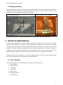
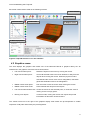
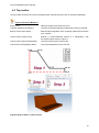
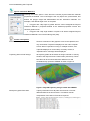
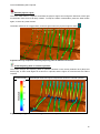
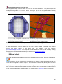
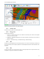
Trajec3D Manual BasRock Software for Geotechs Version 1: April 2015 http://basrock.com/ http://www.facebook.com/basrock4u Frans Basson Rock Fall Modelling with Trajec3D Foreword This is a working document that will be expanded and adjusted in future. Numerical modelling is not a static discipline and the knowledge relating to the subject in a constant state of flux. The subject is also vast and impossible to cover in a single booklet. The author incorporated only the essential knowledge required to equip engineers to assess simple rock fall incidents. The target group for this guideline is site based geotechnical engineers, with the purpose to provide an introductory manual to rockfall modelling with Trajec3D. Only basic concepts are covered and further reading is recommended for engineers who want to pursue the subject in detail. This guideline aims to provide a basic understanding of the principals involved in rock fall modelling, show the working of Trajec3D, and demonstrate potential ways to utilise Trajec3D modelling in a production environment. 2 Rock Fall Modelling with Trajec3D TABLE OF CONTENTS 1. INTRODUCTION ................................................................................ 5 2. OVERVIEW OF ROCK FALL MODELS ............................................. 5 2.1 Lumped mass models .................................................................................................... 5 2.2 Rigid body dynamics ..................................................................................................... 6 2.3 Discrete element ............................................................................................................. 6 3. ROCK FALL VARIABLES .................................................................. 6 3.1 Coefficient of restitution (CR) ......................................................................................... 6 3.2 Friction angles ................................................................................................................ 7 3.3 Fall body size .................................................................................................................. 7 3.4 Fall body shape .............................................................................................................. 7 3.5 Slope geometry .............................................................................................................. 8 4. TRAJEC3D USER MANUAL .............................................................. 8 4.1 User interface ................................................................................................................. 8 4.2 Graphics scene ............................................................................................................... 9 4.3 Top toolbar.................................................................................................................... 10 4.4 Side toolbar................................................................................................................... 15 4.5 Result charts................................................................................................................. 16 4.5.1 4.5.2 4.5.3 4.5.4 4.5.5 Velocity chart ........................................................................................................................... 17 Energy chart ............................................................................................................................ 17 mRL ......................................................................................................................................... 17 Grid .......................................................................................................................................... 17 Histogram ................................................................................................................................ 18 4.6 Physics material interactions ...................................................................................... 18 4.7 Information & Environmental settings ........................................................................ 18 4.7.1 4.7.2 4.7.3 4.7.4 Information ............................................................................................................................... 18 Environment ............................................................................................................................. 18 Simulation ................................................................................................................................ 19 Engine ...................................................................................................................................... 20 REFERENCES.......................................................................................... 21 3 Rock Fall Modelling with Trajec3D FIGURES Figure 1 Types of motion during a rock fall (Lo et al, 2008) .......................................................................... 5 Figure 2 Examples where slope geometry impacts on out-of-plane fall body trajectories ............................ 8 Figure 3 Trajec3D Version 1.6.2.1 user interface .......................................................................................... 9 Figure 4 Steps to buid a custom section ..................................................................................................... 10 Figure 5 Trajec3D trajectory strings loaded with GEM4D ........................................................................... 11 Figure 6 Fall body snapshots indicating trajectory paths at different resolutions ........................................ 12 Figure 7 Trajectory paths colour coding and resolution impact on the outcome ......................................... 12 Figure 8 Custom fall body shape simplifications done by the physics engine ............................................ 16 Figure 9 Extracting information from trajectory paths .................................................................................. 17 4 Rock Fall Modelling with Trajec3D 1. INTRODUCTION Falling rock can experience four types of motion along its path; free fall, rolling, bouncing and sliding. A typical rock fall consists of more than one of these motions during a single event. No interaction takes place between the fall body and slope during free fall, but interaction does take place for all other types of motion during which the rock may also fracture into smaller pieces. During interaction of the fall body with the slope surface (rolling, bouncing and sliding), the behavior is largely governed by the geometries and mechanical characteristics of the slope surface and fall body. (Basson, 2012) Figure 1 Types of motion during a rock fall (Lo et al, 2008) Although computer simulations are used for many reasons, the most relevant to rock falls are: 1. Visualise potential rock fall patterns. 2. Quantify potential outcomes - for example 1 in 5 rocks from a specific bench face will end up on a ramp. 3. Comparative and sensitivity studies with different variables. 4. Exposing surprise events overlooked by visual inspection. 5. Educational tool (toy) that opens the imagination to potential outcomes. 2. OVERVIEW OF ROCK FALL MODELS Three approaches could be used to simulate rock falls; lumped mass, rigid body dynamics, and discrete elements. Each approach has advantages and disadvantages that are briefly discussed. 2.1 Lumped mass models Lumped-mass or stereo-mechanical models represent falling bodies as point masses and ignore the fall object shape and size. The fall body mass does also not affect the overall fall body trajectory, but is only used to compute energy. Lumped-mass models can only represent sliding motion and mimics rotation with a zero friction angle. 5 Rock Fall Modelling with Trajec3D Two fictitious input parameters, the normal and tangential coefficients of restitution, are required for lumped-mass models to compensate for the lack of physics in these simplified models. In reality, the coefficient of restitution depends on factors such as the incident angle, frictional characteristics of the fall body and slope contact, and the collision point on a fall body shape with non-spherical shape. (Curran et.al. 2006) 2.2 Rigid body dynamics Rigid body dynamics modelling is a less sophisticated approach than discrete elements, but still captures the essence of fall body behavior. This approach uses the equations of motion and kinematics, assumes an instantaneous period of contact, and the contact region between colliding bodies are very small. This method is fast enough for real time simulation of multiple fall bodies and even for probabilistic analysis. (Curran et.al. 2006) The input parameters for rigid body mechanics are few, measureable and intuitive. In addition to shape, mass and velocity, rigid body dynamic models only require the static and dynamic friction angles and elasticity of the contacting surfaces. Rigid body dynamics models consider the fall body shape and volume and can solve for all the types of motion, including rotation. 2.3 Discrete element The discrete element method (DEM) code can accurately model rock-slope interactions and even simulate breakup (Curren et.al. 2006), but: 1. Are time consuming to set up. 2. Require many input parameters with some not observable and difficult to estimate. 3. Require an expert user as the software is not user friendly. 4. Are reasonably expensive. 5. Could require high-end hardware. 6. Have slow computational speeds due to the extremely small time steps required. 3. ROCK FALL VARIABLES The parameters that influence rock fall behaviour in rigid body dynamics physics engines are the coefficient of restitution, friction angles, fall body size, fall body shape, and the topography surface. 3.1 Coefficient of restitution (CR) The elasticity or “bounciness” is defined by the coefficient of restitution, a fractional value representing the ratio of speeds after and before impact, taken along the line of impact. A coefficient of restitution of 1 indicates a perfectly elastic collision with no loss in velocity and thus no loss in energy. A value of 0 implies a perfectly plastic collision where all the velocity along the line of impact is absorbed. If such a fall body impacts a surface at an angle, the fall body will not be brought to rest, but the velocity component along the line of impact will be absorbed. 6 Rock Fall Modelling with Trajec3D The velocity coefficient of restitution for an object bouncing from a stationary object is defined as: CR v V where v is the scalar velocity of the fall body after impact and V is the scalar velocity of the fall body before impact. Whe rocks are dropped from a known height onto a horizontal surface, the COR can also be calculated with: CR h H where h is the rebound height and H the drop height. This is an easy way to determine CR-values for different surfaces in the field. (Basson, 2013) 3.2 Friction angles Both a static and dynamic friction angles can be specified in rigid body dynamics physics engines. The static friction angle is only applicable when fall bodies are set to interact, and a body that came to rest is impacted by another moving body. In a typcial rock fall analysis where fall bodies are not interacting, the static friction angle has no importance and can be set to the same value as the dynamic friction angle. Determining the dynamic friction angle for a rock fall is not trivial, as the number is typically not the friction angle of the intact rock. Imagine a large fall body ploughing through a catch berm covered with small broken fragments of rock. The "soft" broken fragments will resist the ploughing movement with a "friction angle" far exceeding the intact friction angle. This is important to consider during analysis, as a low friction angle will allow sliding on the catch berm, and the fall could then contue to following benches in the analysis. 3.3 Fall body size Large blocks are not as easily caught by catch berms as small blocks. The larger blocks tend to fall further, and are less affected by the catch benches, typically resulting in greater maximum velocities than the smaller blocks. By comparison to the fall body size, a catch berm is thus a smaller obstacle for a larger fall body. 3.4 Fall body shape Rounded shapes fall further down a slope than angular bodies. Flat and angular fall bodies are typically the easiest to arrest by catch benches as they tend to slide and do not easily topple and roll down slopes. Rounded volumetric shapes typically runs out substantially further than other shapes, as they easily start to topple and roll down slopes. The anticipated shape of fall bodies in a particular area should thus be carefully considered. 7 Rock Fall Modelling with Trajec3D 3.5 Slope geometry The slope geometry can have a huge impact on fall body trajectories as shown in Figures 2A and 2B. Two dimensional rock fall models do not capture these impacts, and care has to be taken to account for this variability when two dimensional analyses are performed. 2A Out-of-plane bouncing 2B Out-of-plane rolling and sliding Figure 2 Examples where slope geometry impacts on out-of-plane fall body trajectories 4. TRAJEC3D USER MANUAL Trajec3D was developed with a games graphics and physics engine, which are used in commercial games, but also applications. The physics engine implements a deterministic solver that makes it suitable for real-time physics simulations. The physics interaction between materials is a function of the combined properties of the fall body and the impact surface and only three parameters are required; coefficient of restitution, static and dynamic friction angles. As discussed in Section 3, the static friction angle is only applicable when fall bodies are set to interact and has no importance in a typcial rock fall analysis. Keeping the mouse cursor stationary on any interface object (button, check box etc.) will activate a tooltip with a short description of the functionality of that particular object. 4.1 User interface The Trajec3D Version 1.6.2.1 user interface is shown and marked in Figure 3: 1. User interface 2. Graphics scene 3. Top toolbar 4. Side toolbar 5. Result charts 6. Material properties 7. Information box 8 Rock Fall Modelling with Trajec3D Each area is discussed in detail in the following sections. 1. User interface 3. Top toolbar 5. Results chart 4. Side toolbar 2. Graphics scene 6. Material properties 7. Environmental settings Figure 3 Trajec3D Version 1.6.2.1 user interface 4.2 Graphics scene The area displays the graphics and makes use of the Microsoft DirectX 9 graphics library set. All interactions in the graphics scene are mouse driven,where: Left mouse button press: Rotate the objects in the scene by moving the mouse. Right mouse button press: Cancel all selected actions and zoom towards or away from the objects when moving the mouse. When the physics mode is activated and the mouse cursor over a triangulation, this button generates fall bodies close to the triangulation. Middle mouse wheel press: Pan the scene across the screen when moving the mouse. Middle mouse wheel scroll: Zoom towards and away from the objects. Left mouse button double click: Centre the mouse on the selected point, or centre the scene if clicking occurs in empty space. Moving over objects: In some modes, moving the mouse over objects wil provide information as discussion in later sections. The vertical scroll bar to the right of the graphics display area makes the pit transparent to enable inspection of fall paths obscured by the pit triangulation. 9 Rock Fall Modelling with Trajec3D 4.3 Top toolbar The top toolbar accesses the main functionality within Trajec3D and each item is discussed separately. Physics Interaction Material 1 Empty scene: Reset the program and clear the scene. Load the default pit shell (Mat1): Load the pit shell automatically loaded when opening Trajec3D. Build a custom slope (Mat1): Build a slope triangulation from the design parameters and save as a TVM-file. Load a custom section (CSV): Extrude a comma-delimited section to a triangulation, with the required steps shown in Figure 4. Load a custom slopeTVM-file (Mat1): Load a previously build custom slope. Load a DXF pit triangulation (Mat1): Load a pit triangulation from a DXF-file. Figure 4 Steps to buid a custom section 10 Rock Fall Modelling with Trajec3D Physics interaction Material 2 Pressing this button opens a form where the second physics interaction material properties are defined. The cut-off angle is the only aspect not yet discussed, and defines the polygon angle that differentiates the two interaction materials. For example, if the default angle of 20° is accepted: Polygons with a dip angle of greater than 20° will be assigned the Physics Interaction Material 1 properties defined in the "Material properties" section and coloured golden-brown. Polygons with a dip angle smaller or equal to 20 will be assigned Physics Interaction Material 2 and coloured blue-green (teal). Various save options Screenshot to clipboard: Saves a screenshot of the graphics scene to the clipboard, but only works when Trajec3D is displayed on the main computer screen. When Trajec3D is running on multiple monitors, and Trajec3D displayed on a secondary or tertiary monitor, a "Clipboard error" message will be displayed. Trajectory paths as DXF strings: All trajectory paths will be saved as strings coloured on velocity, similar to the output from the "Path"-button (see below). These DXF-files can be accummuated from different runs and simulataneously opened in GEM4D as show in Figure 5. Figure 5 Trajec3D trajectory strings loaded with GEM4D All trajectory path information: Trajecty information from all paths are saved as a commadelimited CSV-file as shown below. This allows manual manipulation of the data in Excel when required. 11 Rock Fall Modelling with Trajec3D Start the physics engine This is the main button in Trajec3D, and starts the physics engine and change the behaviour of the right mouse button from zoom to fall body creation. To stop the creation of fall bodies, press the "Start" button again, or select any other function. The button functions as a toggle switch, and turns green when the physics engine is active 5.0m distance 2.0m distance 1.0m distance 0.5m distance Figure 6 Fall body snapshots indicating trajectory paths at different resolutions Create trajectory paths as coloured cylinders This button changes the trajectory paths to cylinders coloured on the velocity between 0m/s (blue) and 25m/s (red). A colour scale legend is not shown in Trajec3D, and the Figure 7A could be used if a scale is required. 7A Colour scale 7B Example result with Figure 6 trajectories shown as coloured cylinders Figure 7 Trajectory paths colour coding and resolution impact on the outcome 12 Rock Fall Modelling with Trajec3D This action is irreversable, so the fall body "snapshots" are lost after this selection is made and cannot be regained for this particular analysis. Create charts of the selected trajectory path This button activates the chart mode where the mouse cursor changes to a cross, the trajectory path below the cursor is highlighted, and the information of the trajectory path is displayed in the "Results Chart" area (see Figure 3). The specific value applicable to the segment directly below the cursor is displayed on the chart as a number, and dynamically changed as the cursor moves across the path. The button also functions as a toggle switch, and turns green when the charts mode is active. Delete selected or all entities This button allows the deletion of fall bodies, paths, measuirng lines, markers and fenches. The options are self-explanatory, and will not be individually covered. The options can be divided into two groups of similar behaviour. "Delete all bodies, paths, lines, markers and fence", "Delete all fall bodies", "Hide all meshes of all paths", "Delete all measure lines with text", "Delete all markers", and "Delete all fences" are all single actions that execute on the button press. "Delete a single fall body", "Hide meshes of a single path", "Hide a single path mesh", "Delete a single measure line with text", and "Delete a single marker" all require the following actions: o Select the menu option. o Move the mouse cursor over the object (or object set such as a trajectory path) to be hidden or deleted, the object(s) will be highlighted. o Press the "Delete" button on the keyboard. If the delete button is held in, all the object(s) the mouse cursor touches will be affected. This is a usefull to quickly delete or hide a large number of objects. Create fenches The first time this button is pressed after a pit shell was loaded, brings up a form with the physics interaction properties between the fall body and fence, and the fence heigth and angle from vertical. When the button is pressed thereafter, the properties are used and the form not shown again. A single or multiple fenches could be build, and it can be done as individual objects, or as a continuous string of fences. To build individual fences, press the "Create fenches" button after completion of each fence. Build 13 Rock Fall Modelling with Trajec3D continuous fences by pressing the "Shift" button on the keyboard during building. A rigth mouse button click in the scene cancels the action. The button also functions as a toggle switch, and turns green when fence building is active. Create markers Pressing this button bring up a pop-up form where the shape, colour and size can be changed. After pressing "Accept" to confirm the selections, the markers are created at each clicking point until the "Create markers" button is pressed again, or the right mouse button is pressed. Measuring tool After pressing this button, select two points to measure. The result is shown at the start of the measurement as the distance and dip angle between the points. Sectioning tool The sectioning tool cuts away sections of the scene. Define the cut-away with two points, and if done from left to right, the closest part will be hidden. Selecting any other function will unhide the hidden part, or unhide by selecting the sectioning tool again and right clicking in the scene. Create fall bodies on a regular grid The "Rain" button allows the creation of a regular grid of fall bodies across the full footprint of the triangulation below. Different density grids can be created, and the triangulation paths saved with "Save Trajectory paths as DXF-strings". These files can then be loaded simultaneously with GEM4D to create surface flow patterns as shown in Figure 5. Flip polygons Flip the polygons to assist with data inspection. The triangulation can also be made transparent with the slider bar to the right of the scene. Change background colour 14 Rock Fall Modelling with Trajec3D The background colour can be changed to any colour in the available palette. To change back to the default graded background, press the "Colour" button and then press "Cancel" instead of "OK", or close the colour selection form with the top right red cross. Help and About Options to check for program updates and activate the About screen. If "Decline" is pressed on the About Form, the program will exit. 4.4 Side toolbar The toolbar to the left of the scene contans the different fall bodies that could be selected. Mathematical (perfect) sphere shape This shape should not be used for actual rock fall analysis, as a sphere will continue to roll on a flat surface. This shape is useful for theorical analysis though, as the behaviour of a bounce is predictable and only a function of the topography. Mathematical (perfect) flat cylinder shape This shape could be used for actual rock fall analysis, but rolling could still be an issue where the shape acts similar to a spinning wheel. Mathematical (perfect) square box shape This shape is useful for actual rock fall analysis, but should only be used when the actual potential fall bodies are reasonably square. This shape could start to topple and roll below the friction angle of the interaction surface, which does not occur with flat shapes which will rather slide. Mathematical (perfect) flat box shape This shape is very useful for actual rock fall analysis, as fall bodies are often flat slabs that preferentially slide rather than roll. Mathematical (perfect) elongated box shape Use this shape if the actual fall bodies are flat and elongated. Angular (rough) cylinder shape This could be a useful shape for near spherical fall bodies. This shape tends to roll substantially further than flat fall bodies, and will typically give very conservative results. Angular (rough) smartie shape This shape tends to continue further than the angulat flat cylinder shape, as it rolls more easily over the rounded edge. Angular (rough) flat cylinder shape This could be a useful shape for actual rock fall analysis. Multiple bodies for simultaneous release This option shows a form where the number of fall bodies of a particular type could be selected, and the selected fall bodies are simultaneously released to create a large number of fall bodies. 15 Rock Fall Modelling with Trajec3D Custom fall body shape from a DXF-file Any triangulated shape could be loaded as a DXF-file and used as fall body. The physics engine will simplify the triangulation to a concave shape (see Figure 8), but the triangulation will be visually unchanged. 8A Triangulation vs Physics body 8B Android Man as fall body in Trajec3D If the fall body triangulation is Android Man (white), Trajec3D will simplify the physics shape to the convex blue translucent shape. The fall body is represented by the detail wireframe, but the physics engine does the calculations on the simplified convex shape shown to the left. Figure 8 Custom fall body shape simplifications done by the physics engine A detail representation could be made of the fall body by taking multiple photographs from different angles, and then creating a fall object with free software such as 123Catch (http://www.123dapp.com/catch). This shape can then be loaded into Trajec3D, and scaled by entering the appropriate density and fall body mass (see the section on Environment settings). 4.5 Result charts The result charts area contains data charts and grids of selected trajectory paths. When the "Chart" button is pressed, and the mouse cursor moves across the trajectory paths, the path underneath the cursor will be highlighted as shown in Figure 9. The information of the trajectory directly below the cursor is displayed as text on the graph to the left. This text changes as the cursor is moved across the trajectory path. The interval distance between sample points for the graph can be changed in the "Distance" textbox of the "Trajectory path" frame of the "Simulation"-tab, as discussed in Section 4.7 under "Environment". 16 Rock Fall Modelling with Trajec3D Selected trajectory path Data value directly below cursor Figure 9 Extracting information from trajectory paths 4.5.1 Velocity chart Provides the velocity graph of the selected path in m/s. 4.5.2 Energy chart Provides three energy lines: 1. Green line - Rotational Energy due to the rotation of the fall body and a function of the angular velocity and moment of inertia. 2. Purple line - Translational Energy due to the linear movement of the fall body and a function of mass and velocity. 3. Blue line - Total Kinetic Energy = Translational Energy + Rotational Energy. 4.5.3 mRL Provides the vertical displacement of the fall body with time. The centre of the fall body is tracked, and there will thus always be a discrepancy between the vertical displacement and the surface elevation of the topography. 4.5.4 Grid Provides all the data for the selected trajectory path in a data grid. Right click in the grid and select "Copy to clipboard" to copy all the information to the clipboard. 17 Rock Fall Modelling with Trajec3D 4.5.5 Histogram The histogram divides the ditance between the highest and lowest fall body into equal intervals, and counts the number of fall bodies in each bin. The number of bins can be changed in the top-right corner of the chart from "1" and "25". 4.6 Physics material interactions Material properties are not assigned to each material individually, but the physics interaction between two materials is specified. As all fall bodies of an evaluation is assumed to have the same properties, the differentiation between the materials is coloured on the topography. Currently, two materials can be assigned in Trajec3D, with the main material interaction called "Mat1" and shown in golden-brown, and the second material "Mat2" is shown as blue-green (teal). When a triangulation is loaded, it is always done as "Mat1". The second material can then be defined based on the angle from horizontal as discussed in Section 4.3 under "Physics interaction Material 2". The logic behind this approach is that steep surfaces are assumed to be solid rock, and flat surfaces the accumulation of rock fragments. The steeper "Mat1" material interaction thus typically has a higher Coeffient of Restitution than the softer "Mat2" interaction. The softer "Mat2" will typically have a higher Friction Angle than the solid rock as the "soft" broken fragments will resist the ploughing movement with a "friction angle" far exceeding the intact friction angle as discussed in Section 3.2. 4.7 Information & Environmental settings The Information & Environmental settings are at the bottom of the Trajec3D interface. 4.7.1 Information The information box keeps record of actions that were taken during a session. Most button presses will result in the addition of new lines to the information box. 4.7.2 Environment The Environment-tab provides options for changing the global properties, physics modes and interaction types. 18 Rock Fall Modelling with Trajec3D Gravity (m/s2) Gravitational acceleration with the sign indicating the vertical direction. A negative number forces gravity downwards and is the default, and a positive number will pull fall bodies vertically upwards. This number will normally be left as the default value. Density (t/m3) Select the fall body density which determines the size of the fall body with the body weight. Higher densities will result in smaller fall bodies. Body rotation Rotates the fall body around the Z-axis before release. This is not often used, but can be useful if the straight edge of a fall body needs to allign with a topography surface. Body interaction Determines if fall bodies interact with one another, with "Disabled" as the default. Interaction between fall bodies could be usefull when tracking the accumulation of fall bodies in a small volume. For example, when useing Trajec3D to monitor water flows, and an indication of the amount of accumulation at a particular location is required. Mouse collision Determines where mouse cursor collisions will be registred during placement of fall bodies. The default is "Disabled" which only creates new fall bodies when picking on the topography surface. Selecting "Enabled" will create new fall bodies whe picking on the topography surface as well as other fall bodies. Vertical paths The default is "Enabled" except when the "Rain" toggle is on - see Section 4.3 under "Create fall bodies on a regular grid". This selection determines if perfectly vertical paths are recorded. When a fall body bounces from a topography, vertical paths will not occur, but they do occur during the initial free fall when the "Rain" option is selected. When "Disabled", the vertical lines do not obstruct the view, and the redundant information does not consume memory. 4.7.3 Simulation The Simulation-tab provides options for changing the simulation parameters and recorded results. Mass (ton) - Body mass Select the mass of the fall body in tonnes. This value is combination with the "Density" under the "Environment" tab determine the volume (size) of the fall body. 19 Rock Fall Modelling with Trajec3D Time interval between physics calculations This frame encapsulates the parameters that impact on the physics engine accuracy. The sliding bar can be dragged to the right for quicker run-times at the cost of simulation accuracy, or to the left to increase the number of calculations per second for a more accurate result. In the screenshot above, 0.04s is the time between consequtive culculations, and 25/s thus the number of calculations per second. By checking "Real time", the calculation rate will automatically adjust to provide a simulation close to actual time, and useful to obtain an understanding of the time required for a particular rockfall event. This option is not recommended for accurate analysis, as the time between calculations could vary. Checking "Stop time" will stop a simulation until the box is unticked. This is useful to set up a scene with multiple types of fall bodies, and then let them go simultabeously by unchecking the checkbox. Trajectory path This frame encapsulates the parameters that impact on the resolution of capturing and displaying trajectory results. Checking the "Mesh" radio-button will result in capturing of fall body meshes along the trajectory path, and "None" will not capture any fall body meshes but the results will still be captured. To display the results when the fall body meshes were not captured, press the "Path" button on the top toolbar to display the trajectorues as coloured cylinders - see Section 4.3 " Create trajectory paths as coloured cylinders ". The "Distance" value set the approximate distance between result captures, with smaller values resulting in a higher resolution of captured results. The "Scale" value scale the captured fall body mesh to make a very small fall body trajectory path more pronounced. 4.7.4 Engine This tab hosts a few options that are seldom used and of little importance. 20 Rock Fall Modelling with Trajec3D Anti-aliasing is a smoothening filter to reduce the ragged effect from screen pixelation. Anti-aliasing is enabled by default and should not markedly impact performance on modern computers. Multi-threading could accellerate some simulations, but could also cause numerical instability and is disabled by default. REFERENCES Basson F.R.P., 2012. Rigid body dynamics for rock fall trajectory simulation. ARMA 12-267 (46th US Rock Mechanics Association held in Chicago), June 2012. Basson F.R.P., 2013. Coefficient of restitution for rigid body dynamics modelling from on-site experimental data, Slope Stability 2013 (International Symposium on Slope Stability in Open Pit Mining and Civil Engineering held in Brisbane), September 2012. Curran J.H. and Hammah R.E.. 2006. Keynote Lecture: Seven Lessons of Geomechanics Software Development. ARMA/USRMS Golden Rocks 2006, 41st U.S. Symposium on Rock Mechanics, 50 Years of Rock Mechanics – Landmarks and Future Challenges. Lo C.M., Lin M.L. and Lee W.C.. 2008. Talus Deposition Pattern of Rockfall through Mechanical Model and Remote Sensing technology (presentation). Geophysical Research Abstracts Vol. 10, 5th EGU General Assembly. 21