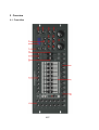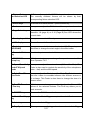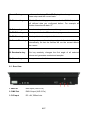
1
SCAN OPERATOR FX II User Manual For Software Version 1.5 email: [email protected] Internet: http://www.glp.de Contents 1 Features........................................................................................................................ 5 2 Overview....................................................................................................................... 6 2.1 Front View............................................................................................................ 6 2.2 Rear View............................................................................................................. 8 2.3 Installation into a 19“ rack.................................................................................... 9 3 DMX Basics................................................................................................................ 10 3.1 Signal transmission............................................................................................ 10 3.2 The cabling......................................................................................................... 10 3.3 The conversion to Light...................................................................................... 11 3.4 DMX Channel Assignments............................................................................... 12 4 Using the Scan Operator FX II..................................................................................13 4.1 Overview.............................................................................................................13 4.2 Operation mode..................................................................................................13 4.2.1 Play Mode...............................................................................................13 4.2.2 Program mode........................................................................................13 4.2.3 Setup Mode............................................................................................ 13 4.2.4 Easy mode..............................................................................................14 4.3 Switching between Modes................................................................................. 14 4.4 Reading the LCD Display...................................................................................15 4.5 Switching to Program Mode............................................................................... 15 4.6 Programming scenes......................................................................................... 16 4.6.1 Creating a new Scene............................................................................ 16 4.6.2 Editing Scenes....................................................................................... 17 4.6.3 Copying a Scene.................................................................................... 18 4.6.4 Copying Fixture Data .............................................................................18 4.6.5 Copying a complete Scene Bank........................................................... 19 4.6.6 Deleting Scenes..................................................................................... 19 4.6.7 Deleting Scene Banks............................................................................ 19 4.7 Programming Chasers....................................................................................... 20 4.7.1 Inserting a Step into a Chaser................................................................20 4.7.2 Insert a Scene Bank into a Chaser........................................................ 21 2/57 4.7.3 Change the editing position of a Chaser ..............................................22 4.7.4 Delete a step in Chaser..........................................................................23 4.7.5 Delete Chasers.......................................................................................23 4.7.6 Delete all Chasers.................................................................................. 23 4.8 Resetting the entire Show Memory.................................................................... 24 4.9 Blackout configuration........................................................................................ 25 4.9.1 Setting up the Blackout function ............................................................25 4.9.2 Resetting the Blackout function .............................................................27 4.10 Overlay scenes.................................................................................................28 4.10.1 Creating and editing overlay scenes.................................................... 28 4.10.2 Deleting Overlay Scenes......................................................................30 4.10.3 Using Overlay Scenes (Play mode)..................................................... 30 4.11 Effect Generator............................................................................................... 30 4.11.1 Effect Patterns...................................................................................... 31 4.11.2 The "Create Wave" Function................................................................ 31 4.11.3 The "Randomize" Function...................................................................32 4.11.4 Creating an effect ................................................................................ 33 4.11.5 Deleting an Effect................................................................................. 34 4.11.6 Running an Effect ................................................................................ 34 4.12 Configuring Fade time function........................................................................ 35 4.12.1 Configuring Fade Channels ............................................................... 35 4.12.2 Resetting the Fade Time Configuration...............................................36 4.13 Inverting channels............................................................................................ 37 4.13.1 Configuring Inverted Channels.............................................................37 4.13.2 Resetting all Inverted Channels........................................................... 38 4.14 Pan and Tilt Encoder........................................................................................ 39 4.14.1 Configuring Pan and Tilt Encoder wheel..............................................39 4.14.2 Using the Pan and Tilt Encoder wheel ................................................40 4.15 Desklock Function............................................................................................ 40 4.16 Autostart function..............................................................................................41 4.16.1 Activating the Autostart Function .........................................................41 4.16.2 Configuring Autostart Desklock ........................................................... 41 4.16.3 Storing current playback condition as a autostart condition................42 4.17 Running Scene Banks (Play mode)................................................................. 43 4.17.1 Running a Scene manually ................................................................. 43 3/57 4.17.2 Running a Scene Bank with Auto Trigger............................................44 4.17.3 Running a Scene Bank with Music Trigger..........................................45 4.18 Manual overwriting channels by using the Faders (Play mode)......................46 4.19 Running a Chaser (Play mode)........................................................................47 4.19.1 Running a Chaser Manually.................................................................47 4.19.2 Running a Chaser with Auto Trigger....................................................47 4.19.3 Running a Chaser with Music Trigger.................................................. 48 4.20 Freeze function.................................................................................................48 4.21 MIDI Control..................................................................................................... 49 4.21.1 The MIDI keyboard mode.....................................................................50 4.21.2 Synthesizer Mode.................................................................................51 4.21.3 Selecting MIDI channel and MIDI mode..............................................52 4.22 Easy Mode....................................................................................................... 53 4.23 Copying the Show Data between 2 Scan Operator FX II................................54 4.24 Editing the Power-On Logo ............................................................................. 55 4.25 Resetting Power-On Logo................................................................................55 4.26 Showing the Software Version......................................................................... 55 5 Technical specifications........................................................................................... 56 5.1 general data....................................................................................................... 56 5.2 DMX Parameter..................................................................................................56 4/57 1 Features 192 DMX channels used by 12 fixtures which 16 DMX channels, each. Assignment can not be changed 240 scenes that can be programmed (30 Banks with 8 scenes per Bank) Extensive effect generator to create automatic Pan/Tilt Movements Autostart Feature and Desklock 6 Chasers consisting of a maximum of 250 steps consisting of the programmed scenes Speed and Fade-Time of all programs (scenes and chaser) can be adjusted 2 Pan/Tilt Encoders, can individually be assigned for each fixture Completely configureable Blackout Master Manual overwriting of any channel during Playback Freeze function to “freeze” the current DMX output Installed microphone for music controlled operation with digital filter that can be adjusted 6 freely programmable and selective Overlay scenes, that can be laid over running programs and Chaser 2 different MIDI (Musical Instrument Data Interface) configurations can be selected (synthesizer operation or optimized for live operation on a 49 key MIDI keyboard) MIDI-controlling of many Play functions, like banks, chaser, Blackout Master, Overlays, Freeze, Auto Trigger, Music Trigger, Tapsync etc. Possibility to invert any channel Fadetime function that can be configured separately for each channel „Easy Mode“, which transforms the controller into a simple 120 channel DMX Faderunit for quick DMX testing or as a Faderunit for other DMX consoles Copy function to copy the whole memory from one controller to another Clearly arranged user interface and an informative LCD display Note: Note that knowledge about MIDI and DMX is necessary for secure and complete control of the desk 5/57 2 Overview 2.1 Front View 6/57 1. Fixture Buttons and Selection LED 12 Fixtures (Lamps) with 16 DMX channels each can be used. The currently selected fixtures will be shown by their corresponding fixture selection LED. 2. Scene keys To access or to save scenes – press scenes key 3. Fader Here you can adjust the DMX data of the respective channel. 4. Page Select key Here you can switch the function of the Faders between channels 1-8 (page A) or 9-16 (Page B).One LED shows the current state. 5. Overlay keys 1-6 Here you access the 6 Overlay scenes. 6. LCD display Shows all current information. 7. Bank keys (UP/DOWN) Here you can switch between the banks 1-30. These keys are also there to change the start angle in the effect editor 8. Record + Delete key Function-keys to record and delete 9. PROGRAM + Setup key With these two keys you change the operation mode of the Scan Operator FX II 10. Speed/Sensitivity Here you can adjust the automatic … (0,12s – 12m 30s). This Fader/FX Speed Fader is also used to regulate the sensitivity of the microphone Fader (slow – fast) and the effect speed. 11. Fade Time/FX Size Fader Here you adjust the Fade time (0 – 32s). The Fade time sets the time it takes to crossfade between two different scenes or of a chaser. This Fader is also there to change the size of a chosen effect. 12. Pan/Tilt Encoder + Fine key With the two encoders, you can directly adjust the Pan and Tilt values of the selected fixtures. The Fine key allows you to work accurate. 13. FREEZE key Turns on the DMX Freeze function. 14. Music/BankCopy Activates the Music Trigger or copies the whole Bank key 15. Auto key Activates the Auto Trigger. 16. Tap Sync / Allows you to manually trigger the chaser when in Auto Trigger 7/57 Manual Go key and learns the timing. The LCD Display then changes between chaser steps and the current bank. 17. Blackout key With the Blackout key you can overwrite the DMX Output with self defined data you configured before. For example all Shutter channels with data “0”. 18. Release key The release key clears all manual changes 19. FX Editor key This key activates the Effect editor in program mode. 20. FX Clear key This key deletes the adjusted effects. 21. Create Wave key This key changes the starting angle of all selected fixtures automatically, so that the fixtures will run the current effects like a wave. 22. Randomize key This key randomly changes the first angle of all selected fixtures and generates randomized samples. 23. Chaser keys Here you access the 6 chasers. 2.2 Rear View 1. MIDI IN MIDI Input (DIN 5-Pin) 2. DMX Out DMX Output (XLR 3-Pin) 3. DC Input DC +9V, 500mA min. 8/57 2.3 Installation into a 19“ rack The Scan Operator FX II can has been built to be directly installed into a 19” rack. No additional installation material is needed. 9/57 3 DMX Basics To operate the Scan Operator FX II, a basic knowledge about the DMX signal transmission, is necessary. This chapter offers a short introduction to the world of DMX data transmission and addresses to beginners and those who have no, or just a little experience with DMX. 3.1 Signal transmission Up to 512 DMX channels can be transferred over a so called DMX cable during a DMX signal transmission. Every DMX channel equals a value of numbers between 0 and 255. A light controller generates the DMX channels and constantly continues them with current values. The Scan Operator FX II sends 192 channels with repetition rate of 36Hz. That means, that all 192 channels are sent 36 times per second. 3.2 The cabling DMX fixtures are being cabled in series. There is only one transmitter but several receivers. The order of receivers on a cable does not matter, because all units receive all data and filter the relevant data. The cabling starts at the transmitter (the lightdesk) and leads to the first DMX set. Beginning at the first DMX Fixture, there’s a cable leading to the second and so on, until the last set is reached. According to the standard you need to plug in a DMX terminator into the last fixture. You can do without this plug if you have smaller cable lengths (20m-30m length of the cable). But please keep in mind, that without that plug, errors might show up in the DMX cabling. The maximum length of the cable is 300m. You can overcome longer distances by a DMX Signal Booster. Hint: A DMX Terminator plug is the same as an ordinary XLR plug, where both DMX data pins (data+ and data-) are connected over a 120Ohm resistor. This minimizes the reflections at the end of the cable, which clearly raises the signal quality. The DMX cables normally consist of one cable according to AES/EBU standard with 5 pin XLR plugs. Instead of using AES/EBU standard cables, often normal microphone cable is being used. This should be considered like not using a Terminator plug: in case of shorter distances it usually works – but might show errors in the DMX cabling as well. 10/57 3.3 The conversion to Light Every DMX Fixture has its own committed amount of operating channels for its functions(like movement, brightness, selecting colors and so on), given by the manufacturer. Since every unit receives all DMX channels of the controller, you have to set every fixture to the right start address. At this start address the set interprets the coming values (per channel a value between 0 and 255) for its functions. You will find Information about which channels exist and what each channel does at a specific value in the User-Manual of the Fixture. Example: We have a fixture with 6 DMX channels. Our lighting controller is sending 192 channels and the data for our DMX fixture is on the channels 100 to 105. Therefore we have to set the start channel to 100 on our fixture, so that it will receive the correct values . The second of 6 channels is, according to the fixtures instruction manual, a dimmer channel. At an adjusted start address of 100, the set will use the data from DMX channel 101 for its dimmer (channel 100=first channel, 101=second Channel and so on). Dimmer channels often use a value of 0 = Dimmer at 0% and DMX value at 255 = Dimmer at 100% - but it does not always have to be that way. For more exact information’s, read the instructions of use for the belonging set. Attention: Some DMX Units start counting at 0, not at 1. Then you set the start channel between 0 to 511 instead of 1 to 512. You will find information about how the fixture counts in the instructions for use of the belonging fixture, as well. Hint: You can set more than one DMX Unit of the same type on the same start address, without any problems. These fixtures will run exactly synchronized, because they are receiving the same data. This way you can connect more than 12 fixtures to the Scan Operator FX II. 11/57 3.4 DMX Channel Assignments The Scan Operator FX II sends 192 DMX channels, which correspond to 12 fixtures with 16 DMX channels per fixture(12*16=192 ). The following table lists the first DMX addresses for each fixture: 1 DMX start address, if you start counting from 0 0 DMX start address, if you start counting from 1 1 2 16 17 3 32 33 4 48 49 5 64 65 6 80 81 7 96 97 8 112 113 9 128 129 10 144 145 11 160 161 12 176 177 Fixture 12/57 4 Using the Scan Operator FX II 4.1 Overview This DMX controller allows to control up to 12 Fixtures with up to 16 DMX channels each. There are 30 Banks with 8 Scenes per Bank.. Out of these 240 scenes you can build up to 6 chasers with each up to 250 steps. The chasers and Banks can be recalled in different ways: Manually Music Trigger Predefined Chase Time (Auto Trigger), that is given over the „Tapsync“-key or Speed Fader MIDI command 4.2 Operation mode All together there are 4 different operation modes in which different functions are available. When you turn on the unit, you start directly in the play mode. Hint: The current mode is always shown in the first line in the display! 4.2.1 Play Mode This mode is there to play the scenes, banks and chasers you have programmed before. There are different ways to let the banks and chasers tap automatically. The Desk also reacts to given MIDI commands. 4.2.2 Program mode It is possible to program the whole scenes, effects, banks, chasers, overlays and blackouts in this mode. 4.2.3 Setup Mode The Setup mode is used to configure the Scan Operator. You can configure the midi channel, the midi control mode (between synthesizer and keyboard), reverse DMX 13/57 channels, turn on the Fade-time function for each channel and alter the assignment of the Pan/Tilt wheels. The Pan/Tilt wheels can be assigned per fixture to one channel (1 to 16), each and can be an alternative Pan/Tilt adjustment opportunity besides of the appropriate channel faders. 4.2.4 Easy mode The easy mode is Therefore quick testing of DMX controllable units or to extend bigger DMX desks , where a extra DMX fader unit would be useful. Here there are 12 fixtures with 10 channels each that are manually given (over the 10 faders). The scene keys respond as flash keys for the first 8 channels of each set. The Blackout function turns all 120 DMX channels to 0. Other functions (except Desklock function) are deactivated. Technical reference: In easy mode , similar to play mode, 192 DMX channels are being sent. The channels 1-120 can be, as written above, controlled by the user. The channels 121-192 will be constantly transferred with value „0“. 4.3 Switching between Modes To activate the different modes, press the belonging key for 3 seconds: Program mode: PROGRAM key Setup mode: SETUP key Easy mode: PROGRAM+SETUP key simultaneous Switching between all modes can be done by pressing the belonging key. The Play mode can be reached by pressing the key, which brought you into the current mode again for 3 seconds. Examples: If you are in setup mode and want to change to program mode, press the program key for 3 seconds. If you are in program mode and want to go back to play mode, just press the program key again for 3 seconds. 14/57 4.4 Reading the LCD Display The LCD display consists of 2 lines of each 8 signs. The display is intensively used to show the current condition. In a normal condition it always shows the current mode in the first line. In the line below you can find information to the belonging mode. In Play Mode you have the current bank and the current scene shown in the second line. If a chaser is activated, it will be shown at the end oft he first line. In Program mode you can also see the current bank and scene in second line. Besides that there is a extra „Overlay Bank“ that should be marked with „Overlay“. In Setup Mode you can see the belonging menu point in second line, which you can configure now. The following menu points can be chosen: “MIDI” to configure the MIDI channel and MIDI assignment “Invert” to reverse channels “Fadetime” to configure Fadetime channels “Tilt” to configure the Tilt Encoder wheel “Pan” to configure the Pan Encoder wheel „Autostart“ to configure the Autostart options In Easy Mode the second line is blank. Besides that the display also shows a short confirmation or an error report. These overwrite the current information of the display for a few seconds. Afterward the display turns back to its normal condition. Examples fur such short reports are „Memory Reset“, „Scene Saved“, „MIDI Set / Keyboard“, „Fader XY / Value ABC“ … 4.5 Switching to Program Mode After turning the unit on you are in PLAY Mode. By pressing the Program key for 3 seconds you change to program mode. Here scenes, effects and chasers can be created and the Blackout functions as well as the Overlay scenes can be configured. After pressing the program key again for 3 seconds, you return to play mode. 15/57 4.6 Programming scenes 4.6.1 Creating a new Scene A scene is an adjustment of all 192 DMX values of different DMX sets including a possible Pan/Tilt effect for each fixture. Up to 240 scenes can be stored. The scenes are subdivided in 30 banks with each 8 scenes. 1. Activate PROGRAM mode (PROGRAM key). 2. Select desired Fixtures with associated Fixture keys. Thereby several Fixtures can be selected at the same time. 3. Adjust the desired DMX values (0 to 255) with the Fader. 4. If you need to change to channels 9-16 press the “Page” key. If you’d like to edit channel 1-8, just press the “Page” key again. Repeat the steps 2-4 until all DMX values correspond to your desires. Hint: By pressing the RELEASE key you can set all 192 channels back to the DMX value "0" at any time and start altering the values again. For storing continue with step 5: 5. If the current bank does not match the desired bank, then you might select the desired bank using the BANK keys. 30 banks are available. You can store up to 8 Scenes in each bank. If the desired scene is created, then you can store it in the Scan Operator by pressing the RECORD key once. 6. Afterward press the scenes key, which you would like to store the scene to. 16/57 As a memory confirmation you’ll receive the message "Scene Saved". After that, the display will show the current bank and scene. 7. Continue the steps 2-7 until all desired scenes are stored. 8. To leave PROGRAM mode, press the PROGRAM key for 3 seconds. 4.6.2 Editing Scenes 1. Activate PROGRAM mode (PROGRAM key). 2. Press BANK UP/DOWN key to call up the desired bank in which the scene, that shall be edited is on. 3. Load desired scene by pressing the appropriate scenes key. Now you can change and store again, as in the case of creating. Attention: Loading a scene that is not containing any values is not possible! In that case you receive the error message "Scene Empty". 4. Make the desired changes with the Faders. Select the appropriate Fixtures, for that, previously. 5. After you made the changes you press the RECORD key. 6. Press the previously selected scenes key again, to store the changes. You will receive the message "Scene Saved". Hint: Of course the now changed scene can be stored in another scene or even on a different bank. Therefore it is possible to quickly create the appropriate scenes for chases, where each step of the chase should be based on the same scene, but a little different. 17/57 4.6.3 Copying a Scene 1. Activate PROGRAM mode (PROGRAM key). 2. Press the BANK UP/DOWN key to call up the desired bank in which the scene that shall be copied is on. 3. Load the scene which you would like to copy by pressing the appropriate scene key once. Attention: Loading an empty scene is not possible! In that case you receive the error message "Scene Empty". 4. Press the BANK UP/DOWN key to call up the desired bank which the scene shall be copied to. 5. Press the RECORDS key. 6. Press the scenes key which you want to copy the chosen scene to. As confirmation you will receive the message "Scene Saved". 4.6.4 Copying Fixture Data This function allows you to transfer the current DMX values from one fixture to another in PROGRAM mode (COPY). 1. Keep the Fixture key, which you want to copy, pressed 2. While you keep the first Fixture key pressed, press the desired second Fixture key on which you want to copy. 3. In the display the signature "COPY" appears short as confirmation. 4. For example you can also press further Fixture keys, without releasing first, in order to copy the same settings on further Fixtures. Attention: These changes take place in the buffer only. If you want to store the new scene, then proceed as described above (RECORD and then scene key)! 18/57 4.6.5 Copying a complete Scene Bank 1. Activate PROGRAM mode (PROGRAM Key). 2. Press the BANK UP/DOWN key to call up the desired bank you would like to copy. 3. Press the RECORD key. 4. Press the BANK UP/DOWN key until you reached the bank you would like to copy to. 5. Press the MUSIC/BANK COPY key. As memory confirmation you receive the message "BANK COPY". 6. Press the PROGRAM key for 3 seconds to leave the PROGRAM mode again. 4.6.6 Deleting Scenes 1. Select the bank, in which the scene that shall be deleted is located. 2. Keep the DELETE key pressed and press the scenes key of the scene that you would like to delete. As confirmation you receive the message "Scene Deleted". Attention: A deleted scene cannot be restored again! 4.6.7 Deleting Scene Banks 1. Select the bank, which you would like to delete. 2. Keep the DELETE key pressed and press the MUSIC/BANK key at the same time. 3. All scenes of this bank were deleted. For confirmation you receive the message "Bank Deleted". 19/57 4.7 Programming Chasers A Chaser is a program, which calls at maximum of 250 scenes successively. You must have programmed the scenes, from which you "build up" the Chaser, before. Should you change scenes later, the program of the Chaser changes as well. Should a scene in which a chaser is used, be deleted afterward, then the chaser will not load the scene, since it is empty. 4.7.1 Inserting a Step into a Chaser With this function you can insert a scene, which is loaded, straight into a Chaser (behind the current step of the Chasers). 1. Activate PROGRAM mode (PROGRAM Key). 2. Press the Chaser key that you would like to program a Chaser to. Only one Chaser can be programmed at a time. Hint: If you switch on a Chaser that is already containing steps in the Program mode, then this jumps automatically to the last step of its programming. Inserting takes place at the end of the Chasers. 3. Load one of the scenes that you stored to one of the banks before, by pressing the appropriate scene key. 4. Press the RECORD key. 5. As confirmation of inserting the display shows the message "Scene Inserted". 6. Repeat the steps 3 and 4 to arrange the desired program. You can store a maximum of 250 steps in a Chaser. 7. If a Chaser has reached the maximum number of steps, the display shows the message "Chaser Full". 20/57 4.7.2 Insert a Scene Bank into a Chaser You might copy a whole bank into a Chaser as well. In this case the controller will insert all existing scenes on that bank into the chaser automatically (If the chaser is containing steps already, it will insert the steps at the end). If the bank is empty, then nothing is inserted. 1. Activate PROGRAM mode (PROGRAM Key). 2. Select the desired Chaser with the CHASER keys 1-6. Hint: 3. If you switch on a Chaser that is already containing steps in the program mode, the point of editing will automatically be set to the last step of the chaser. Inserting now takes place at the end of the Chaser. Press the BANK UP/DOWN key to call up the bank on which the desired scenes were stored to. Press the MUSIC/BANKCOPY key. 4. Press the RECORD key. As memory confirmation you will receive the message "bank Inserted". 21/57 4.7.3 Change the editing position of a Chaser Since the functions for inserting a bank and for inserting a step always insert it behind the current step of a chaser, it can be desirably, in particular during the rework of a Chaser, to change the current editing position. 1. Activating PROGRAM Mode (PROGRAM key). 2. Select the desired Chaser, if it is not yet activated. Hint: If you switch on a not empty Chase in the Program mode, then the editing position will be the last step of the chaser. Inserting takes place at the end of the Chasers. 3. Press the TAPSYNC key. You now see the current Chaserstep: "step xxx" in the Display. 4. Press the BANK UP/DOWN key to go to the desired step. Example: Should a scene between the Chaserstep 3 and 4 be inserted, jump forwards until the display shows "step 003". Hint: At the upper and lower end the step number jumps back to the other end of the chaser. Therefore the last reserved step of the chaser is at step “0” again. Hint: The 0-th step does not exist; it only serves as a dummy step for editing the Chaser. You can select it, in order to insert a scene or a bank at position “1”. 5. In order to insert a scene or a bank behind the new position now, you press the TAPSYNC key again, in order to return to the previous screen. Hint: With the TAPSYNC key you change between the screen of the Chaserstep and the bank/scene. 6. For inserting the scene you proceed, as described further above. 22/57 4.7.4 Delete a step in Chaser The deletion of a Chaserstep is only possible in the Chaserstep announcement, since you can choose the step that you want to delete only here. 1. Activate PROGRAM Mode (PROGRAM key). 2. Select the desired Chaser which contains the step that should be deleted. 3. Press the TAPSYNC key. The last step of the Chaser is now indicated in the LCD display 4. Press the BANK UP/DOWN key to change to the Chaserstep which should be deleted. 5. Press the DELETE key to delete the indicated Chaserstep. As memory confirmation you will receive the message "step deleted". Hint: The steps, which lie behind the deleted step, all slip a step forward now and the new step at the deleted position is now being loaded. Therefore pressing the DEL key 3 times , deletes 3 steps starting after the current Position 4.7.5 Delete Chasers You can likewise delete an entire Chaser. Afterward the chaser does not contain any steps. 1. Activate PROGRAM Mode (PROGRAM key). 2. Keep the DELETE key pressed. Additionally press the appropriate Chaser key. 3. As delete confirmation you will receive the message "Chaser Deleted". 4.7.6 Delete all Chasers 1. Keep the two keys Bank UP and Bank DOWN pressed in the switched off condition of the set 2. Switch on the CONTROLLER again. All Chasers are now deleted. 3. As confirmation you will receive the message "Chasers Deleted". 23/57 4.8 Resetting the entire Show Memory This function clears and initializes the entire show memory. After the deletion the Memory will be in the following condition: All scenes are deleted All Chaser are deleted All overlay scenes are deleted The Blackout-Key overwrites all 192 channels with the value "0” No channel is inverted The pan channel for each Fixture is channel 1 The Tilt channel for each Fixture is channel 2 The MIDI channel is channel 1 The MIDI allocation is adjusted to the "MIDI keyboard" allocation The autostart function is deactivated For deletion you proceed as follows: 1. The controller is switched off. 2. Hold the Program and Setup keys pressed while you switch the controller on again. 3. For confirmation you will receive the message "MEMORY RESET". 24/57 4.9 Blackout configuration 4.9.1 Setting up the Blackout function You can program the Blackout function freely according to your desires. You can set whether each channel of any fixture will be overridden, and if so, with which value. It is possible to configure the Blackout function so that it only closes the Shutter of all fixtures but the movements and effects continue to run. The Blackout Function can be set up with the following steps: 1. Activate PROGRAM Mode (PROGRAM key) 2. Now select the bank 31 and/or the position, where the bank 31 would be. The display will now show "Overlay". You can now configure the Blackout function like a normal scene. 3. If you want to provide a new Blackout function, then you can continue directly with step 5, if you follow the following reference. Hint: If you want to overwrite a few channels only (for example the Shutter channel of the lights), it is advisable to press the “Release” key first, which sets all channels to “Off”. Afterward only the channels that should really be overwritten, can be turned on. 4. However If you would like to edit the existing Blackout function, load it now by pressing the Blackout key once. 5. Select the desired fixture with the appropriate Fixture key. Several Fixtures can be selected at the same time. 6. Use the scenes keys, in order to switch the channels on or off individually. The display will show a short message saying "Channel XY: On "or" Channel XY: Off". "On" means that Blackout overwrites this channel fo the selected Fixtures. 7. With the Faders you can set the desired values. You might Output values, which are not to be overwritten (status "off”), as well. This can be sense full for programming, for example if you would like to switch on a dimmer, in order to see that the Shutter is really “closed”. The Blackout function will ignore these values later, if they were stored with the status "off". 25/57 8. Repeat the steps 3 to 6, in order to configure further Fixtures 9. If the desired Blackout function is provided, then store it by pressing the RECORD key. 10. Afterward press the BLACKOUT key. The procedure corresponds to the sequence, as if you wanted to store a normal scene on the Blackout -Key. 11. For confirmation you will receive the message "Scene Saved". 12. Press the PROGRAM key for 3 seconds to leave PROGRAM mode. Hint special case: You should be certain that you only overwrite channels, which are not affected by the Fade-Time (see Fade time attitudes). This ensures, that when you deactivate a Blackout again, all channels directly jump back to their current values. If you overwrite a channel, which is affected by the Fadetime. the Fade time will be applied to this channel when you switch the Blackout off, which then results in a slow return from the Blackout Values for this channel. This case arises naturally only if the Fade time function is being used, and if the Fader-Time Fader is not on position zero. Otherwise this special case is insignificant. 26/57 4.9.2 Resetting the Blackout function With this function you can reset the Blackout to it’s default values. This means that all 192 channels receive the status "on" and are overwritten the value "0". After the deletion of the entire memory this is the case likewise (see above). For setting the Blackout-Scene back you proceed as follows: 1. Activate PROGRAM mode (PROGRAM key) 2. Now select Bank 31 and/or the position, where the bank 31 would be. The display now shows "overlay". 3. Keep the DELETE key pressed and press the BLACKOUT key at the same time, in order to set the Blackout function back to its default values. For confirmation you will receive the message "Blackout RESET". To set the Blackout scene back, this is loaded automatically. 4. Press the PROGRAM key for 3 seconds to leave PROGRAM mode. 27/57 4.10 Overlay scenes The Scan Operator FX II offers 6 selective overlay scenes which you can edit freely. These scenes work exactly, like the Blackout function described above, but on a lower priority level: Overlay scenes overwrite selected channels with predefined values in Play Mode. As example, it is possible to vary running programs by adding, I.e. strobe effects or colors or gobos. Hint: Since the Blackout function has a higher priority than the overlay scenes, the Blackout function will overwrite any activated overlay scene. 4.10.1 Creating and editing overlay scenes For providing or editing the overlay scenes you precede as follows: 1. Activate PROGRAM mode (PROGRAM key) 2. Now select bank 31 and/or the position, where bank 31 would be. The display now shows “Overlay". You can now configure the overlay scenes, like a normal scene. 3. If you want to provide a new overlay scene, then you can directly continue with step 5. There is no channel being overwritten first. 4. However, if you would like to edit the existing overlay scene, then load it now by pressing the appropriate overlay scene key. Hint: Empty overlay scenes cannot not be loaded. In this case the message appears "OL Scene Empty" in the display. 5. Select desired Fixtures with appropriate Fixture keys (LED on). Several Fixtures can be selected at the same time. 6. Use the Scene keys, in order to switch the channel on or off individually. In the display the respective condition will be shown with "Channel XY: On "or" “Channel XY: Off”. “On" means that this channel of the selected fixtures will be overwritten. 28/57 Hint: By pressing the "releases" key you can set all channels back to the value 0. Also all channels will be switched to "off" again, so that you can begin to program a new overlay from ground up. 7. You can set the desired values wit the faders. You might also set the values of the channels, which will not be overwritten (status "off"). However, these will not be overwritten later, if the overlay scene is called up. 8. If necessary, press the PAGE key, in order to be able to change the further 8 DMX of channels (9-16). 9. Repeat the steps 3 to 6, in order to configure further Fixtures. 10. If the desired overlay scene is programmed, then store it in the Scan Operator, by pressing the RECORD key once 11. Afterward press the appropriate overlay scene key, which you would like to store it to. The procedure corresponds to the sequence, as if you wanted to store a normal scene on overlay a key. For confirmation you receive the message "Scene Saved". Hint: If you should provide several overlay scenes one after the other, then you would eventually like to set, after providing a overlay scene, all channels on "OFF" again, in order to provide the next overlay scene from a firm starting point. You can reach this very simply, by pressing "release" key. All channels are set on "off" again and overwritten with the value "0". To leave PROGRAM mode, press PROGRAM key for 3 seconds. 29/57 4.10.2 Deleting Overlay Scenes For the deletion of an overlay scene you proceed as follows: 1. Activate PROGRAM mode (PROGRAM key) 2. Select bank 31 and/or the position, where the bank 31 would be. The display will show "overlay". 3. Keep the DELETE key pressed and simultaneously press the key of the overlay scene, which you would like to delete. For confirmation you will receive the message "Deleted". 4. To leave PROGRAM mode, press the PROGRAM key for 3 seconds 4.10.3 Using Overlay Scenes (Play mode) In order to call up an overlay scene in Play mode, these must have been provided before in Program mode. Now you can load one of the 6 overlay scenes, in order to change the current program. You can only activate one overlay scene at a time. Renewed pressing deactivates the overlay scene again. 4.11 Effect Generator The Effect Generator allows you to use 12 predefined movement patterns for Pan/Tilt and store them together with normal DMX values into a scene. The different movement patterns can be selected and adapted in size, speed and starting angle. Effects can be programmed independently for each fixture. The output of the effects value for each fixture is added to the channels that are defined as Pan and Tilt in the Setup Menu (Default is channel 1/2). Thus the produced values of an effect are added to the Pan/Tilt values stored in the scene. The base values that are stored inside the scene can be regarded as the center position of the effect. 30/57 4.11.1 Effect Patterns The Scan Operator FX II offers 12 different effect patterns for Pan/Tilt: "Circle CW" produces a circle in clockwise direction "Circle CCW" produces a circle against the clockwise direction "sine" produces a sinusoidal movement. Altogether 4 different sine movements stand to the selection, which differ in their direction: sine up/down sine right/left sine diagonally left sine diagonally right "Sawtooth 1" produces a saw tooth movement on the pan channel "Sawtooth 2" produces a saw tooth movement on the Tilt channel "Triangle" produces a movement in the triangle "Linear" produces a linear up/down movement on the Tilt channel "Jump" produces a movement jumping in the square. "Wild" produces an overlay various sine and Cosines curves, which lead to a soft, comparatively fast and asymmetrical movement. This effect can be combined for example with a small beam gobo at slow speed. In connection with the "Randomize" function several fixtures develop a spotlight effect independently of each other. 4.11.2 The "Create Wave" Function If you selected an effect in the effect editor, then you can use this key, in order to let the starting angles ("off sets") automatically manipulate the selected Fixtures. With this key the starting angles of the selected Fixtures are varied in such a way that successively 3 different kinds of undulations can be produced. So that this function supplies a correct result, it is necessary that the starting angles of all selected fixtures are identical before using the key. This is automatically the case, if you selected a new effect. Now if you press the key uniquely, a wave is produced forwards. 31/57 Renewed operation changes the wave in such a way that each second lamp makes one 180° shifted movement first (allocation in straight and oddly selected lamps). After a third pressing of the key, the wave will be reversed. A fourth pressing of the key returns again to the starting situation of the starting angles. Example: You select all Fixtures in the Program mode and open the effect editor. As center of the effect you adjust the DMX value "128" for pan and Tilt over the Fader. Now you select the effect "sine up/down" and select any speed and size. All 12 fixtures will implement the same sine wave off and on synchronously now. As soon as you press the "Create Wave" key once, a synchronous movement turns into a wave, which goes through the lamps successively. After repeated pressing the 12 lamps divide themselves into odd and straight lamp numbers. One drives high while the other lamps drive exactly opposite to the sine movement, downwards. Repeated pressing lets a backwards running wave develop and after a fourth pressure on the key, the wave disappears again. 4.11.3 The "Randomize" Function If you selected an effect in the effect editor, then you can use this key, in order to let the starting angles ("off sets") automatic manipulate the selected Fixtures. With this key the starting angles of the selected Fixtures are changed in a coincidental way, so that an asynchronous movement develops. The starting angles for pan and Tilt are differently changed, which leads to the fact that for example a circulation must no longer remain an absolute circulation. The result of this function is coincidental. Repeated pressing produces a new distribution of the starting angles with each pressure. If you would like to cancel the "Randomize" function again, then you simply reload the current effect through pressing the associated effect key. The adjusted size and speed remain, if you load the effect again. Example: You select all Fixtures in the Program mode and open the effect editor. As center of the effect you adjust the DMX value "128" for pan and Tilt over the Fader. Now you select 32/57 the effect "Wild" and select any size, and a slow speed. All 12 fixtures will implement synchronously the "Wild" movement now. After pressing the Randomize key the starting angles for pan and Tilt become randomized. This leads to it that all fixtures move, however each lamp drives another way. If you combine this with a small point Gobo now, then you produced a "searchlight" effect. 4.11.4 Creating an effect In order to create an effect, you proceed as follows: 1. Activate PROGRAM mode (PROGRAM key) 2. Start the effect by pressing the "FX editor" key. Now the 12 keys of the effects section should light up 3. Select desired lamp with their Fixture key. Several Fixtures can be selected at the same time. 4. Now select the desired effect by pressing the appropriate effect key. 5. With the “FX Speed" and "FX Size" Faders you can change the size and speed of an effect for the selected fixtures. Size and speed can be selected in 8 stages in each case. 6. With the keys "Offset+" and "Offset -" and/or. "Bank UP" and "Bank down" you can increase and/or manually make a smaller starting angle ("offset") of the selected lamps in 90° steps. Alternatively the starting angle can be varied by means of "Create Wave" or "Randomize" key (see above). 7. With the Faders you can still adjust DMX values while the effect editor is activated. Pan and Tilt of values function thereby as center of the selected effect. 8. If necessary you press the PAGE key, in order to be able to change the further 8 DMX of channels (9-16). 9. Repeat the steps 3 to 8, in order to provide effects for further lamps. 10. You can delete an effect for the selected Fixtures at any time, by operating 33/57 the "FX CLEAR" key. 11. As soon as you finish the providing of the effects, leave the effect editor again by pressing the "FX editor" key. You can now, as usual, store the DMX effect into a scene. 12. If you finished the storing of the scenes, then you leave the PROGRAM mode again pressing the PROGRAM key for 3 seconds. 4.11.5 Deleting an Effect If you are in the "Program mode", then you can delete the adjusted effect of all selected Fixtures at any time by pressing the "FX CLEAR" key. It is not necessary to activate the effect editor. Please, note the fact that if you want to delete the effect from an already created scene, you have to load the scene first, then delete the effect and afterwards you must store the scene again. 4.11.6 Running an Effect The provided effects are a part of a scene. The effects are thus played automatically with the scenes, into which they are stored. 34/57 4.12 Configuring Fade time function As already described above, it is possible to define channels that are able to “crossfade” with the time given by the Fade time fader. The controller generates intermediate steps, which automatically slow the movement down. It is meaningful thereby that these intermediate steps are only to be generated for movement and possible Dimmer channels. Therefore this configuration option offers you the possibility of defining in which channels the Fadetime has to work and in which it does not. 4.12.1 Configuring Fade Channels To change the Fade time of channels you proceed as follows: 1. Activate SETUP mode (SETUP key). 2. Now select "Fadetime" in the setup mode menu. You can change the Fade Time channels now. 3. Select desired fixtures with appropriate Fixture key. Multiple fixtures can be selected at the same time. 4. Use the scenes keys, in order to switch the channels on or off. In the display the respective condition is shown by “Channel XY: On” or “Channel XY : Off”. "On" means that the Fade time function for this channel is activated on the selected fixtures. 5. If necessary press the PAGE key, in order to be able to change the further 8 DMX channels (channels 9-16). 6. Repeat the steps 3 to 5, in order to configure further fixtures. Important: The changes are not automatically durably stored but they are directly active. Therefore it is necessary that you confirm the changes for durable storing once with the RECORD or the SETUP key. 7. Press the SETUP key for 3 seconds to leave the Setup mode again. 35/57 4.12.2 Resetting the Fade Time Configuration In order to reset the Fade time function for all channels, you proceed as follows: 1. Activate Setup mode (SETUP key). 2. Now select “Fadetime". In the menu of the Setup mode. 3. Press the DELETE key. For confirmation you will receive the message "Fadetime RESET". Important: The changes are not automatically durably stored but they are directly active. Therefore it is necessary that you confirm the changes for durable storing once with the RECORD or the SETUP key. 4. Press the SETUP key for 3 seconds to leave Setup mode again. 36/57 4.13 Inverting channels Each of the 192 channels can be inverted individually. Inverting takes place in the Setup menu and is deleted likewise with the deletion of the entire memory. 4.13.1 Configuring Inverted Channels To toggle the inversion of one or more channels you proceed as follows: 1. Activate Setup mode (SETUP key). 2. Now select „Invert" in the menu of Setup mode. You can now invert the channels. 3. Select desired fixtures with appropriate Fixture keys. Several fixtures can be selected at the same time for configuration. 4. Use the scenes keys, in order to individually switch the channels on or off. In the display the respective condition will be shown as “Channel Inverted" or “Channel normal”. 5. If necessary press the PAGE key, in order to be able to change the further 8 DMX channels (channels 9-16).Repeat the steps 3 to 5, in order to configure further fixtures. Important: The changes are not automatically stored but they are directly active. Therefore it is necessary that you confirm the changes for durable storing once with the RECORD or the SETUP key. 6. Press the SETUP key for 3 seconds, to leave the Setup mode again. 37/57 4.13.2 Resetting all Inverted Channels In order to reset all inverted channels, proceed as follows: 1. Activate Setup mode (SETUP key). 2. Now select "Invert" in the menu of Setup mode 3. Press the DELETE key. For confirmation you will receive the message "Invert RESET". Important: The changes are not automatically durably stored but they are directly active. Therefore it is necessary that you confirm the changes for durable storing once with the RECORD or the SETUP key. 4. Press the SETUP key for 3 seconds, to leave the Setup mode again. 38/57 4.14 Pan and Tilt Encoder You can assign the Pan/Tilt Encoder wheels for each Fixture to one of the 16 DMX of channels in each case. They serve as additional input mode for Pan and Tilt values beside the appropriate DMX faders. In addition the effect generator also falls back to the channels adjusted here, if Pan/Tilt effects are produced. You can make change Pan and Tilt values of different DMX fixtures, even if the DMX channel reservation is different. So Pan/Tilt can be on the channels 1/2 on set 1 and on channel 5/6 on set 2. By using the Pan/Tilt Encoder wheels you can access the Pan/Tilt of both devices. After a deletion of the entire memory, channels 1 and 2 are assigned to the Pan/Tilt wheels for each Fixture. 4.14.1 Configuring Pan and Tilt Encoder wheel In order to assign to the Pan and Tilt Encoders to a channel, you proceed as follows: 1. Activate the Setup mode (SETUP key). 2. Now select "Pan" or “Tilt” in the menu of the Setup mode 3. Select desired fixtures with appropriate fixture keys. Several fixtures can be selected at the same time for configuration. 4. Use the scenes keys, in order to assign a pan and/or Tilt channel to the selected Fixtures of the current channel. In the display the respective channel is then confirmed with "Channel pan XY" or “Channel Tilt XY". 5. If necessary you press the PAGE key, in order to be able to change the further 8 DMX channels (channels 9-16). 6. Repeat the steps 2 to 5, in order to configure further fixtures. Important: The changes are not automatically durably stored but they are directly active. Therefore it is necessary that you confirm the changes for durable storing once with the RECORD or the SETUP key. 39/57 4.14.2 Using the Pan and Tilt Encoder wheel You can use the pan and Tilt Encoder of wheels both in the Program and in the Play mode. The Encoder wheels change the accordingly configured Pan/Tilt DMX channels in each case. The Fine button regulates if, whether per click on the Pan/Tilt wheels, either to 1 DMX step (Fine On) or 8 DMX steps (Fine Off) are made. 4.15 Desklock Function The CONTROLLER offers a Desklock function, which can disable the user interface and block any user interaction. You activate and/or deactivate the Desklock by pressing the PAGE SELECT key while you are already keeping the PROGRAM and SETUP key pressed together. While the Desklock is active, all user inputs are ignored. The MIDI input is not affected by the Desklock. Toggling power to the device deactivates the Desklock as well unless you have set it up in the autostart setup to be activated automatically when the device is powered on. Please read the following chapter about "Autostart function". 40/57 4.16 Autostart function The Scan Operator FX II offers an Autostart function, which repairs the stored playback condition by switching the set on and off. In addition the possibility exists that when switching the set on, the Desklock is activated automatically. 4.16.1 Activating the Autostart Function In order to activate the Autostart mode, you proceed as follows: 1. Activate Setup mode (SETUP key) 2. Now select "Autostart" in the menu of Setup mode (shortened by "Autostrt"). 3. Now use the Pan Encoder, in order to activate and/or deactivate the Autostart function. Important: The changes are not automatically durably stored but they are directly active. Therefore it is necessary that you confirm the changes for durable storing once with the RECORD or the SETUP key. 4. Press the SETUP key for 3 seconds, to leave the Setup mode again. 4.16.2 Configuring Autostart Desklock In order to activate the Desklock mode automatically when switching on of the equipment on, you proceed as follows: 1. Activate Setup mode (SETUP key). 2. Now select "Autostart" in the menu of Setup mode (shortened by "Autostrt") 3. Now use the Tilt Encoder, in order to activate and/or deactivate the Autostart function. Important: The changes are not automatically durably stored but they are directly active. 41/57 Therefore it is necessary that you confirm the changes for durable storing once with the RECORD or the SETUP key. 4. Press the SETUP key for 3 seconds, to leave the Setup mode again. 4.16.3 Storing current playback condition as a autostart condition If you activate the Autostart mode, then you can store the current playback condition as an Autostart condition. This condition is then restored when switching on the Scan Operator. The following parts are stored as Autostart condition: The chosen bank and the current active scene Running chasers and their playback position Active overlays The trigger source (manual, auto or music) and their current setup (auto speed or music sensitivity) The current Fadetime To store the current condition, keep the RECORD key pressed while pressing the TAPSYNC key. The display shows „Autostrt Saved“. Attention: Please, note that the Autostart mode must have been activated before in Setup menu. If this should not be the case and you try to store the current playback condition as an Autostart condition, there will be a reference on the display saying “Autostrt disabled”. 42/57 4.17 Running Scene Banks (Play mode) 4.17.1 Running a Scene manually 1. After turning the CONTROLLER on it is automatically in the Play mode. 2. Make sure that the manual trigger mode is selected (see the “Manual LED” to the right of the display). 3. Use the BANK UP/DOWN keys to call up the bank with the desired scenes. 4. Call up the desired scene with the scenes keys. Hint: You can use the TAPSYNC/MANUAL GO Button at any time, if the device is not running in Auto Trigger Mode, to manually advance to the next Scene. This is useful for example in Music Trigger, if you wish to go on to the next Scene manually during a silent part of the music. 43/57 4.17.2 Running a Scene Bank with Auto Trigger This function makes it possible to let a bank of scenes or a Chaser run automatically in a loop. 1. Press the AUTO key to call up this function. The auto trigger timing that has been used last is restored automatically and indicated in the display. The Auto LED lights up. 2. Use the BANK UP/DOWN keys to select the desired bank. 3. Now you have different possibilities of playback control: Speed Fader: This gives playback speed "NEXT time". The respective time is indicated in the display (max. 1 step all 12min 30sec). TAPSYNC Button: Pressing this button at least twice during Auto Trigger mode sets a new speed for the Auto Trigger according to the given tap speed (the Tapsync button is able to learn speeds down to 32 sec). 4. Adjust the crossfade time Fade Time: Tells us how fast the crossfade to the next step is. The slowest crossfade time is thereby 32s. The time refers to an over-dazzle time of value 0 to 255. Smaller movements are done faster. 5. In order to deactivate the auto trigger, press the AUTO button again. Hint: You can use the TAPSYNC/MANUAL GO Button at any time, if the device is not running in Auto Trigger Mode, to manually advance to the next Scene. This is useful for example in Music Trigger, if you wish to go on to the next Scene manually during a silent part of the music. 44/57 4.17.3 Running a Scene Bank with Music Trigger 1. Press the MUSIC/BANKCOPY key to activate the music trigger. The music sensitivity that has been used last is automatically restored and indicated in the display. The MUSIC LED lights up. 2. Use the BANK UP/DOWN keys to select the desired bank. The occupied scenes of this bank will be started one after another controlled by the music input. 3. Use the music speed Fader during the music trigger, in order to change the sensitivity of the microphone. Thereby you can select from "Fast" to "Slow". "Slow" reacts relatively sensitively - "Fast" rather insensitively. Hint: With sensitivity not the volume of the microphone is regulated (the hardware of the equipment does that automatically), but it the minimum duration of the bass impacts and the minimum time between two bass impacts is being changed. When switching on the set the value "normal" is selected automatically. This is a good default value, which nearly always fits. 4. Adjust the crossfade time Fade Time: Tells us how fast the crossfade time to the next step is. The slowest crossfade time thereby is 32s. The time refers to an over-dazzle time of value 0 to 255. Smaller movements are done faster 5. Press the MUSIC/BANKCOPY key to deactivate the Music Trigger again. Hint: You can use the TAPSYNC/MANUAL GO Button at any time, if the device is not running in Auto Trigger Mode, to manually advance to the next Scene. This is useful for example in Music Trigger, if you wish to go on to the next Scene manually during a silent part of the music. 45/57 4.18 Manual overwriting channels by using the Faders (Play mode) You can overwrite Play mode channels by means of the Fader. This function is meant, to do smaller changes in live performance. In order to overwrite channels, you proceed as follows: 1. You are in Play mode 2. Select desired fixtures with appropriate Fixture keys. Several fixtures can be selected at the same time for configuration. 3. Adjust the desired DMX values (0 to 255) with the Faders. 4. If necessary press the PAGE key, in order to be able to change the further 8 DMX channels (channels 9-16). Repeat the steps 2-4 until the all DMX of values correspond to your desire. 5. The accomplished changes have priority before, for example, active overlay scenes and remain to exist, until you waive the changes through pressing the RELEASE button again. 46/57 4.19 Running a Chaser (Play mode) Hint: You have to have programmed the Chaser before in order to call it up. Empty chasers can not be started. 4.19.1 Running a Chaser Manually 1. Select the desired Chaser 1-6. By renewed pressing of the chaser key you deactivate it again. 2. Make sure that Auto and Music Trigger are deactivated. 3. A new started chaser is loaded directly and begins with its first step. Hint: Several chasers can also be selected at the same time. These run off then successively. In the display the up-to-date running chaser appears at the end of the first line. 4. With the Tapsync key you can move on to the next step now. 4.19.2 Running a Chaser with Auto Trigger 1. Select at least one of the desired chasers 1-6. By renewed pressing of the chaser key you deactivate a chaser again. Hint: Several Chasers can be selected at the same time. These run off then successively. 2. Press the AUTO key to call up this function. Auto LED lights up. 3. Select the desired playback time with the speed and Fade time faders and/or with the TAPSYNC/MANUAL GO key. 47/57 4.19.3 Running a Chaser with Music Trigger 1. Select the desired Chaser of 1-6. By renewed pressing of the Chaser key you deactivate it again. Hint: Several Chasers can be selected at the same time. These run off then successively. 1. Press the MUSIC/BANKCOPY key to call up music function. The music LED lights up. 2. Select, with the speed and Fade time faders the desired expiration effect.. Hint: You can use the TAPSYNC/MANUAL GO Button at any time, if the device is not running in Auto Trigger Mode, to manually advance to the next Scene. This is useful for example in Music Trigger, if you wish to go on to the next Scene manually during a silent part of the music. 4.20 Freeze function The Freeze function freezes the current DMX output until its deactivation. This is useful, if you want stop the entire movement briefly, and to let it run again after a short time as before. All parameters are maintained. This also means that for example the Auto Trigger for each Fixture stays in sync after a Freeze. 1. This function is available only in Play mode 2. Pressing the FREEZE button toggle the freeze function On and Off. 48/57 4.21 MIDI Control This controller can receive MIDI command in Playback Mode to trigger different memories and playback options. You can choose between 2 different MIDI modes: MIDI Synthesizer Mode Here the individual scenes of the first 15 banks are directly accessible via MIDI. In addition the Chaser and the Blackout function can be controlled. MIDI Keyboard Mode This mode is optimized to use the controller in live environments with a 49 keys MIDI keyboard. The 30 banks as well as the 6 Chaser are directly callable as programs. Not only with the Chaser and the Blackout function, but also the Freeze function, auto trigger, music trigger, Tapsync and the overlays can be controlled. In both modes the "Pitch Wheel" and "Modulation Wheel" (= MIDI CONTROLLER type # 1) control the functions of the speed and of the Fade time Faders over MIDI. Pitch Wheel: The pitch wheel controls the function of the speed Fader. Hint: If the Auto Trigger is active, then the controllable range is limited to max. 10,96s. This simplifies the handling in live environments, since larger values are mostly not desired and the resolution of many pitch wheels is not sufficient, in order to enter smaller values with sufficient accuracy. Modulation Wheel: The Modulation Wheel controls the function of the Fade time Fader in the range of 0s32s. 49/57 4.21.1 The MIDI keyboard mode This mode is optimized, to use the Scan Operator in live environments with a 49 keys MIDI keyboard. The 30 banks as well as the 6 Chaser are directly callable as programs. You can also control the Blackout and the Freeze function as well as the functions for trigger setup. Hint: Our tests resulted that it is possible without problems, to change scenes over MIDI (with a Synthesizer or a computer) over 30Hz. The MIDI functions of this set are sufficiently fast for live environments. Keys Keys 1..30 (white and black) MIDI Note Function 36 37 38 39 40 Bank 1 on Bank 2 on Bank 3 on Bank 4 on Bank 5 on 64 65 66 Keys 31..36 67 (white and 68 69 black) 70 71 4. and 5. 73 last black 75 keys The last 3 78 black keys 80 82 72 74 76 The last 8 77 white keys 79 81 83 84 Bank 29 on Bank 30 on Overlay 1 on / off Overlay 2 on / off Overlay 3 on / off Overlay 4 on / off Overlay 5 on / off Overlay 6 on / off Freeze on Freeze off Auto Trigger on / off Music Trigger on / off Tapsync/Manual Go Chaser 1 on / off Chaser 2 on / off Chaser 3 on / off Chaser 4 on / off Chaser 5 on / off Chaser 6 on / off All Chasers off Blackout on/off 50/57 4.21.2 Synthesizer Mode Here the individual scenes of the first 15 banks are directly accessible by MIDI. In addition the Chaser and the Blackout function can be controlled. BANK 1 BANK 2 BANK 15 (last Bank) CHASER 1 CHASER 2 CHASER 3 CHASER 4 CHASER 5 CHASER 6 Chaser OFF BLACKOUT MIDI Note Funktion 00 01 02 03 04 05 06 07 08 09 10 Scene 1 Scene 2 Scene 3 Scene 4 Scene 5 Scene 6 Scene 7 Scene 8 Scene 1 Scene 2 Scene 3 112 113 114 115 116 117 118 119 120 121 122 123 124 125 126 127 Scene 1 Bank 15 on/off Scene 2 Bank 15 on/off Scene 3 Bank 15 on/off Scene 4 Bank 15 on/off Scene 5 Bank 15 on/off Scene 6 Bank 15 on/off Scene 7 Bank 15 on/off Scene 8 Bank 15 on/off Chaser 1 on/off Chaser 2 on/off Chaser 3 on/off Chaser 4 on/off Chaser 5 on/off Chaser 6 on/off All Chasers off Blackout on/off 51/57 Bank 1 on/off Bank 1 on /off Bank 1 on /off Bank 1 on /off Bank 1 on /off Bank 1 on /off Bank 1 on /off Bank 1 on /off Bank 2 on /off Bank 2 on /off Bank 2 on /off 4.21.3 Selecting MIDI channel and MIDI mode 1. To arrive at the Setup mode, press the SETUP key for 3 seconds. You are directly in the MIDI point of menu. 2. With the Pan Encoder wheel can now adjust the MIDI channel. 3. With the Tilt Encoder wheel you can switch between the different MIDI modes ("Synthesizer" and "Keyboard"). Important: The changes are not automatically durably stored but they are directly active. Therefore it is necessary that you confirm the changes for durable storing once with the RECORD or the SETUP key. 4. Press the SETUP key for 3 seconds, to leave the Setup mode again. 52/57 4.22 Easy Mode The EASY mode serves for fast tests of DMX fixtures or as additional Faderdesk for larger DMX Desks, which for which a DMX Faderunit is sense full. Here 12 Fixtures with 10 channels each are used. The values of the channels are specified over the 10 Faders of the set (including Fade time and speed). The scene keys serve as Flash keys for the first 8 channels of each set. The Blackout scene switches all 120 DMX channels to 0. Other functions (up to the Desklock function) are deactivated. In EASY mode you can change DMX values as follows: 1. In order to get to the EASY mode, press the PROGRAM+SETUP key for 3s. The Display now shows the Text “Easy”. 2. Now select the Fixtures, which channels you would like to change. 3. You can change the values of the 10 channels per fixture over the Fader. The PAGE key is functionless. 4. Repeat the steps 2 and 3, in order to use other devices. Hint: You can test fast and simply DMX sets in EASY mode or use this desk as "dummy” DMX Faderunit for larger desks. 5. The scenes keys have the function of a Flashkey in this mode. As long as one of these keys are pressed, this channel will be sent with a value of "255" This is then indicated in the display by the text "Flash". Hint: The channels 9 and 10 do not have Flash key. 53/57 4.23 Copying the Show Data between 2 Scan Operator FX II It is possible to transfer all memory contents of one Scan Operator FX II to another one. Use the following steps to transfer the memory: 1. Both controllers are switched Off 2. Connect both devices with a DMX Cable (XLR 3-Pin Male-Male) 3. Make sure that all Midi cables are unplugged 4. On the receiving controller hold down the buttons „Fixture 7“ and „Fixture 12“ simultaneously while switching it On. 5. The display now shows "Serial/Rec. 000% ". The desk is ready to receive data. 6. On the sending controller hold down the buttons “Fixture 1” and “Fixture 6” simultaneously while switching it On. 7. The Display of the sending controller is showing "Serial/send xxx%" and the percentage value will count up slowly. The value shown in the controller that is receiving the date should increase as well. The transmission procedure lasts approximately 90 seconds. 8. The transmission has finished successfully, when both units have reached 100%. In the case of errors: It might happen that the receiving unit stops with the progress below 100% - If that happens, try to restart the data transmission. If the waiting controller shows no reaction, although the other unit is sending data, then the error probably comes from a faulty DMX connection! 54/57 4.24 Editing the Power-On Logo You can edit the Logo, which is shown when switching the Unit on, according to your own desires. In order to do this, you switch the Unit on, while you keep the AUTO key pressed. You can change now change the position of the cursor with the Pan Encoder Wheel. The letter at the selected position can be changed with the Tilt Encoder Wheel. As soon as you finished editing the text, you need to store it with the "RECORD" key. The display shows the message "Logo Saved". Switch the Scan Operator on and off, again. 4.25 Resetting Power-On Logo In order to reset the Logo, switch on the unit while pressing the AUTO button. Now press the "DELETE" button and store the result by pressing the "RECORD" button. Now you can restart the Scan Operator FX II. Hint: The Logo is not deleted, if you use the function that clears the entire show memory! 4.26 Showing the Software Version If you keep the MUSIC/BANK COPY button pressed when switching the Unit on, the Software Version of your Scan Operator FX II appears in the display. 55/57 5 Technical specifications 5.1 general data DC Input ……..........................................................................................DC 9V, 500mA DMX Exit ...........................................................................................3 pol, female XLR MIDI Signal ........................................ .............................................5 pol, DIN Standard Audio Control ................................................................................. Built-In Microphone Dimensions ......................................................................................482 x 176 x 73 mm Weight .................................................................................................................2,5 Kg 5.2 DMX Parameter Channels sent............................................................................................................192 Break..................................................................... ................................................151us Mark after Break..................................................... ..........................…....................24us Channeltime (Frametime + Mark after Frame).........................................……........49us DMX Framerate.......................................................................................................36Hz 56/57 57/57